磁通门电流传感器说明书
SICK MZ2Q 磁感应电子门磁传感器说明书

P R O D U C T I N F O R M AT I O NMZ2Q-T:easy teaching, intelligent handling.MZ2Q-C:compacter’s not possible.It’s great when it’s not the quantity but the quality that counts!Like the MZ2Q-T and MZ2Q-C magnetic cylinder sensors for the T- and C-slot.Developed in order to permit even quicker and more economical end-position definition and intermediate position detection on pneumatic cylinders or grippers. The secret: two adjustable switch points with just one slot occupied!This saves mounting space and cabling effort – and thus time and money.Insert: simply insert into the slot from above and turn.Positioning: centre the sensor and affix it.First teach-in: place the piston in the desired 1st position and perform the 1st teach-in.M Z 2Q –T H E I D E A L S O L U T I O N F O R T - A N D C -S L O T SFor end-position definition on short stroke cylinders and for intermediate position detection on pneumatic cylinders and grippers.Flexible installation:a single sensor for differing cylinder types – due to specific accessories.Mounting brackets for profile and tie-rod cylinders, for pneu-matic cylinders with dovetail slots, and for round-bodied cylinders are easily installed and permit universal use ofboth MZ2Q models.Second teach-in: place the piston in the desired 2nd position and perform the 2ndteach-in.SICK AG | Waldkirch | Germany | I N D U S T R I A L S A F E T YS Y S T E M SComprehensive protection forman and machine – advancedSICK products developed andmanufactured by a sensorspecialist for the protection ofhazardous areas, hazardouspoints and for access protection.SICK is setting new standardswith services related to machinesafety.A U T O I D E N TWhether the tasks involveidentification, handling, classifi-cation or volume measurement,innovative Auto Ident systemsand laser measuring systemsfunction extremely reliably, evenunder rapid cycle times. Theyconform to the latest Standardsand can be simply and speedilyintegrated in all industrial en-vironments and external appli-cations.ANALYZERS AND PROCESSINSTRUMENTATIONSystem control, maintainingsetpoints, optimising processcontrol and monitoring the flowof materials – the instrumentsand services for Analysis andProcess Measurement, suppliedby SICK MAIHAK, are settingthe standards for these appli-cations in terms of Technologyand Quality.I N D U S T R I A L S E N S O R SOur complete range of sensorspro v ides answers to suit anyapplication in the field of auto-mation. Even under rugged ambi-ent conditions objects are reli-ably detected, counted and posi-tioned in respect of their form,location and surface finish, aswell as their distances establis-hed with pin-point accuracy.R A N G E O F E X P E R T I S E。
AUR°EL HCS-Keeloq 无线磁电子门窗传感器说明书

User ManualLe caratteristiche tecniche possono subire variazioni senza preavviso. La AUR°EL S.p.A non si assume la responsabilità di danni causati dall’uso improprio del dispositivo.WIRELESS MAGNETIC CONTACTThe magnetic contact wireless MAG HCS is a sensor able to detect opening or closing doors or windowsand transmits via radio a alarm signal. It is composed of two distinct elements: a case containing the magnetic contact and electronic card normally placed on the frame of the fixture and a small permanent magnet to fit on the mobile element of the fixture. The working is based on the closing and opening of a sensor capable to operate within a 10-15mm radius from the permanent magnet.MAG HCS is battery power by (CR2032) supplied and designed to ensure autonomy of 2-3 years, it is always internallycontrolled by a meter charge that forwards via radio the battery life time and warns by a beeper and LED, the alarm of discharged battery.It’s available a double auxiliary block terminal independent from internal magnetic contact, where it’spossible to connect a second sensor, eg further magnetic contact, sensor for rolling shutters or other type of sensor that uses a free NC contact. Internal electrical card manages this independent contact and the event of case opening and consequent sends a unique radio code.Other functionalities are: the tamper, which is activated in the event of tampering of the enclosure, the tear can be activated by removing of the sensor installed, a software periodic supervision that communicates via radio the battery status, tamper, magnetic contact independent alarm condition. The radio protocol is a rolling code type, and unique code programmed in AUREL for each sensor. A LED shows radio transmissions, alarms and test.Fig.1 – Sensor and magnetFig. 2 – PCB sensor side1) Sensor2) Permanent Magnet3) Dip switch: not assembled in HCS version4) Jumper 1-4: Setting mode (see "Sensor Configuration). 5) Reed:select magnetic contact with open JP36) Reed: select magnetic contact with closed JP37) Tamper: tamper switch8) Aux In:AUX INPUT9) Battery:batteria mod. CR2032 tipo Litio10) Buzzer:Low battery indicator11) LED:light signals (see signaling) 12) Antenna:please do not modify it* HCS and Keeloq are brand Microchip3JP1 JP2JP3 JP4 6 5127 8124User ManualLe caratteristiche tecniche possono subire variazioni senza preavviso. La AUR°EL S.p.A non si assume la responsabilità di danni causati dall’uso improprio del dispositivo.Fig. 3 – battery PCB sideSensor configurationJumpers allows to setup different operation mode and tests. Do not activate at the same time jumper JP1 and JP2, if you activate jumper JP1, be sure JP2 is not active! After 10 minutes from last jumper status change, sensor configuration mode is off, in order to reset this configuration, take off the battery and insert back after tamper button will press.JP1 Radio Mode JP2 SupervisionJP3 Magnetic contac selection JP4 Magnet settingTab.1 – sensor config.RADIO MODE: allows to verifythe radio link between sensor and receiver. It’s activate once JP1 is closed. Radio transmission works for 30 seconds, then switch on normal works.SUPERVISION FUNCTION : It sends to the receiver side a signal to give a feedback of the status battery and the status of the magnetic, tamper , tear contacts.It’s activated from the closing of JP2 contact, it’s foreseen a transmission each 60 seconds independent from the alarm signal.CALIBRATION OF MAGNETIC SENSOR: It’s a function used during learning procedure of the sensor that helps the installer to place the permanent magnet near the magnetic contact.It is triggered by the closure of JP4 the LED switches on when the magnet closes the magnetic contact and switches off when the contact opens. No radio transmission is activated.After 5 minutes from the starting of the procedure, the sensor will come back to the normal function. To start again the function, disconnect and fit again JP4.MAGNETICCONTACTSELECTION: allows to select, if both are present, one magnetic contact REED depending from the assembly. Selection is made by JP3 if closed, active contact is the one fitted on the large PCB side, if open is the one fitted on the short PCB side.JP3 closed Reed active on large PCB side JP3 open Reed active on short PCB side1012911User Manual MAIN WORKING:Normally is activated after the fitting of the battery or when “RADIO MODE” AND “CALIBRATION OF MAGNETIC SENSOR” functions are finished. The sensor sends the status code when there is a variation of the operation, eg opening or closing of any contact (see "SPECIFICATIONS OF THE RADIO CODE). The led switches on for 100 ms to show the transmission. The time transmission is about 1 sec.Acoustic and luminous signal.are present 1 buzzer and 1 red LED with the following functions:BUZZER: Used to signal low battery and it’s activated when the battery voltage drops below 2.35 volts with a duration time of 2-3 seconds.LED is activated for each radio transmissions (alarm, supervisory radio test). If the case of low battery (below 2.35 V), it blinks quickly for 2 seconds every 5 minutes. The calibration function of the magnetic sensor remains on when the magnetic contact is closed.Technical featuresMin Tipico Max UnitàPower supply (1) 2.1 3 3.3 VCurrent consumption Tx 12 15 mACurrent consumption stand-by 4.0 5.0 6.5 uALow battery 2.1 2.25 2.35 VoltBattery life 2 (1) 3 yearsRadio transmissionStandard frequency OOK modulation433.82 433.92 434.02 MHzModulation OOK On-Off KeyingEffected Radiated Power (E.R.P) 0.5 1.0 mWERP second harmonic < 1GHz -36 dBmERP third harmonic > 1GHz -30 dBmElectromagnetic immunity10 V/mCodifica KeeloqSerial code 28 bitHopping code 32 bitHopping combos 2³² -Working temperature-10 +55 °CCase Dimension 70,4 x 33,6 x 17,4 mm(1) Tipo Litio 3V CR2032Radio code featuresMAG 4MHCS implements the Microchip's Keeloq rolling code with Aurel manufacturer code, customizable on request. The parameters of the protocol Microchip Keeloq are not disclosed and are available on request. The radio transmitted codes related to different functions of MAG HCS are described below. Consider that the S0-S1-S2-S3 codes refer to the 4-bit encoding used by Keeloq (see the documentation about the Microchip Keeloq):Le caratteristiche tecniche possono subire variazioni senza preavviso. La AUR°EL S.p.A non si assume la responsabilità di danni causati dall’uso improprio del dispositivo.User ManualLe caratteristiche tecniche possono subire variazioni senza preavviso. La AUR°EL S.p.A non si assume la responsabilità di danni causati dall’uso improprio del dispositivo.MAGNETIC CONTACT: represented by S3 bit and it has high logic level when the contact is opened or low logic level when the contact is closed.TEAR AND TAMPER CONTACT: they use the same bit S2 and it goes high when one of the two contacts is open. S2 goes low when both are closed.AUXILIARY INPUT: represented by S0 bit and it goes high when the contact is open and low when it’s closed.RADIO MODE: all bits (S0-S1-S2-S3)are at “zero” logic level and this function is used for test radio transmission or learning the radio code in the central unit.SUPERVISION: represented by S1 bit it has high logic level once radio code Supervision is emittedFig.4 –Back frameFig.5 – Back sensorInstallation:1)Place the back frame (fig. 4)on the fixture making sure to turn the magnetic sensor tothe moving part of the frame where the permanent magnet is placed. Then mark the holes printed on thebottom box (see fig. 3), 5-6 mm drill with drill and secure the bottom2)Place the permanent magnet on the mobile part of the fixture trying to match the reference marksin thecase of the sensor and permanent magnet. If the magnet is sufficiently close to the magnetic contact, LEDwill switch on indicating the closure of the magnetic contact. However, the sensor will not be installed at a distance greater than 30mm from the permanent magnet.Fixingholes hookshooksUser Manual Learning procedure and radio test:Prepare the receiver side in the learning mode.Activate the "radio mode" of the MAG 4MHCS by closing JP1 and JP2. The radio will operate for about 30 seconds.Note: The installation of MAG HCS on metal frames can cause radio performance losses. In this case it is advisable to install the magnetic sensor away from screening components and connect an external magnetic contact to the auxiliary inputInstallation with connection to the auxiliary input.Il MAG HCS implement intermally a NO contact, usable from a another sensor The figure above shows a typical application of sensors connected in series to help protect a single device with multiple windows. The various contacts must be connected in series, the opening of one of them will cause the alarm. This scheme will not allow the state opening of each frame.This contact can also be used with any other type of sensor that has a dry contact output NO / NC.Fig.7 – Principio di utilizzo e collegamento del contatto ausiliario del sensore magneticoBattery substitutionThe substitution of the battery must be carried out when the sensor transmits the low battery alarm by radio signal or led or buzzer. However the battery is not completely discharged and will ensure a couple of weeks of working.To substitute, procede as follow:remove the top side of the case, replace the 3V mod. CR2032 litium battery being careful to the polarity, see picture number 8. To obtain a higher time life, five years life time batteries are advised. The accidental reversal of polarity of the batteries does not cause the breaking of the circuit and discharging them. In the case of loosing of substances , remove it taking care to not get in contact with them. Throw used batteries in respect of the normative. See the section 'Information for users'.Le caratteristiche tecniche possono subire variazioni senza preavviso. La AUR°EL S.p.A non si assume la responsabilità di danni causati dall’uso improprio del dispositivo.User ManualLe caratteristiche tecniche possono subire variazioni senza preavviso. La AUR°EL S.p.A non si assume la responsabilità di danni causati dall’uso improprio del dispositivo.Fig. 8 – battery substitutionINFORMATION FOR THE CUSTOMERThe product you purchased, must be separately throw and it can not be thrown as municipal waste, as required by Directive 2002/96/EC. Therefore, this system and all its components, subsystems andconsumables materials that are part of the product, when you take the decision to discard them, must be thrown to collection centers for proper treatment of waste, according as provided by law. To know where these centers are located, you should ask at the municipal offices.CE DECLARATION OF CONFORMITYThe magnetic contact MAG 4MHCS is under the follow normative: ETSI EN 301 489-3 V1.4.1 – Electromagnetic compatibility ETSI EN 300 220-1 V2.3.1 – Radio features EN 60950 – Other featuresCE ReferenceIn the back of the plastic case that encloses the transmitter is present a label with the identification of the module as those reported here at the left side [product name, manufacturer, voltage supply and currentsupply].+ on the top- on the backPull the battery。
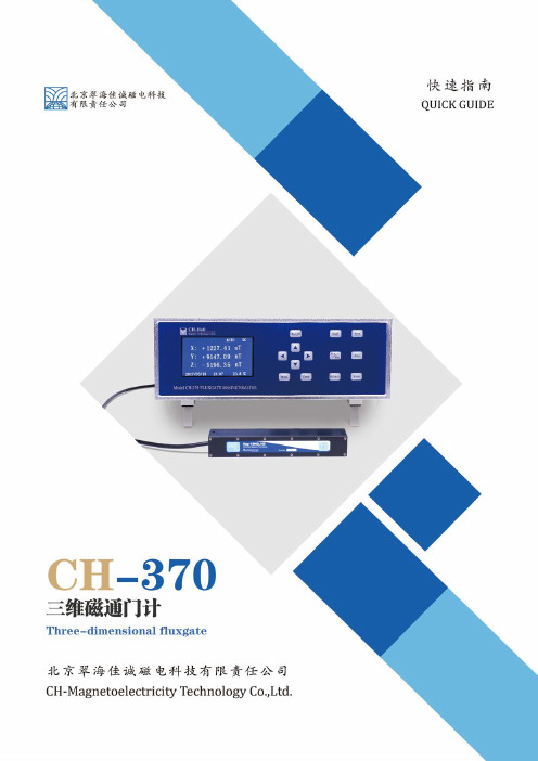
CH-370三维磁通门计说明书
公司介绍北京翠海佳诚磁电科技有限责任公司(原翠海科贸公司)是一家专业从事全数字自动化测磁系统,高精度数字磁检测设备及数字磁场控制的科技型公司。
依托中科院的先进技术研发和生产高精度一维、二维和三维霍尔探头(带温度补偿)及多维高精度高分辨率测磁仪并通过ISO9001及IQNET国际体系认证,多项性能及参数均可达到国际先进水平,且多次被航天、军工、航海、科研及院校应用, 并受到广泛的好评。
我公司可以根据用户的需求,研发、生产多种测磁系统,包括多点阵列磁扫描系统和工业自动化检测系统、远程有线与无线控制系统、磁屏蔽系统、地磁补偿系统和特种高斯计、磁通门计、高精度磁场控制平台、计量检定系统(我公司使用的精度为:读数的±0.002%——±0.0002%)、多维磁场分析扫描系统、多维电机磁场测试分析系统、多极磁环测试系统、地磁屏蔽测磁系统、霍尔效应测试系统、线圈及电磁铁等等定制产品,同时代理国际尖端测磁仪器公司产品。
地理位置地址:北京市海淀区丰豪东路9号院中关村集成电路设计园2E-409电话:************400-139-1007传真:************网址:内容摘要CH-370简介 (1)快速入门 (2)按键功能及显示介绍 (4)后面板定义 (5)探头介绍 (6)CH-370简介CH-370三维磁通门计是北京翠海佳诚磁电科技有限责任公司设计并制造的用于测量弱磁场强度的极高精度高分辨率全智能化仪器。
特点明亮的全视角VGA/5¾位读数分辨力基本精度:读数的±0.2%±0.05%量程最大值/最小值保持/界面锁定基本分辨力0.1nT数据存储(自动/手动) /存储数据阅读自动零点、自动量程探头自动校正/主机自动记忆操作模式RS-232C/USB数据通讯接口/模拟信号接口显示单位可选nT 归零设置/相对测量模式测量软件图形显示,通讯波特率调节阈值设定(上,下限)及报警时间及亮度设定可选的基本探头参数尺寸320×130×285 mm维数 3量程±100μT零场偏移误差±5nT误差温度系数±0.3nT/℃分辨率0.01nT准确度<读数的0.2% ±5nT响应频率≤3kHz传感器噪音标准:6 to ≤10pTrms/√Hz at 1Hz L(低):6pTrms/√Hz at 1Hz三维正交性误差<0.1°预热时间15分钟满足缩放规格,<60分钟满足噪音规范磁滞<2nT 于1 x 满量程温度范围工作温度-40℃至+70℃储存温度-40℃至+85℃探头尺寸32×32×225 mm 通讯RS-232模拟输出3通道BNC配套软件数据读取软件快速入门检查和开封首先请检查运输包装是否存在外部损伤和部件缺失,如果损伤或缺失比较明显,请尽快与运输商和我公司联系。
OMEGA FMG70系列磁通流传感器产品说明书

H-XXHElEctromagnEtic low FlowmEtErU No Moving PartsU No Flow Obstructions U Maintenance-Free U F ast Response Time (< 500 ms)U M inimal Straight Pipe RequirementsThe FMG70 Series from OMEGA is a trio of extremely compact, low cost, inductive magnetic flow sensors. This product lineallows a unique and highly reliable measuring technique to beintroduced into areas of process control previously considered not possible.Changes of temperature, density, viscosity, concentration or electrical conductivity (minimum conductivity of 50 µs/cm) of the fluid do not affect the output signal.FMG70 series can be used in areas where flow sensors with moving parts e. g. paddle wheel sensors,SPeciFicaTiONSMaterials of constructionelectrodes and Process connection: Stainless steel 316 TIMeasuring Pipe: PEEK-GF30Gasket: EPDMHousing: Cast Aluminum accuracy: ±2% of reading Repeatability: 2%Minimum conductivity: 50 µs/cmMaximum Liquid Temperature: 90ºC (194°F)ambient Temperature: 5 to 70ºC (41 to 158°F)Maximum Pressure: 16 bar (232 psi)Flow indication: LED green, flow proportional blinkingFrequency: Square wave signal NPN, internal pull-up resistor 2 k Ω pulse duty ratio 50:50Signal current Maximum: 20 mA, current limitedResponse Time: <500 mSelectrical connection: Plug connector M12 x 1Power Supply: 24 Vdc ±10%current consumption: Maximum 80 mAelectrical Protection: Measures short-circuit proof (up to 30V) and polarity protection (up to -30V)Protection class: NEMA 4X (IP65)Flow Range:FMG71: 0.95 to 18.9 LPM (0.25 to 5.0 GPM)FMG72: 1.89 to 37.9 LPM (0.5 to 10.0 GPM)FMG73: 9.46 to 189.3 LPM (2.5 to 50.0 GPM)analog Output Signal (“-a” Models)4 to 20 ma (0 to Full Scale):current Limitation: 26 mA approx. Maximum Load: 250 Ω to GNDcannot be applied due tocontamination/particulate in the media. The sensor is intended for continuously measuring of flow rates or for dosing/batching of electrically conductive liquids (minimum conductivity 50 S/cm).The output signal frequency (or current) is proportional to the flow.T wo options are available for output signals, frequency oranalog (-A Models).FMG71 shown actual size.FMG71 shown withDPF701 meter/totalizer. Visit/dpf701 to order.FMG70 SeriesFMG7312 (0.47)142 (5.59)~ 81 (3.2)M12x1Light emitting diodeplug M12x1Nut size 34 (1.338)6.05.04.03.02.01.00.0P r e s s u r e d r o p ∆p (p s i )0 2 4 6 8 10 12Flow rate (US gal/min)Flow rate (US gal/min)0 10 20 30 40 50 60P r e s s u r e d r o p ∆p (p s i )2.01.51.00.50.0FMG72FMG71FMG73®29(1.15)1 NPT/BSP25(0.98)~ 76 (3.0)35(1.36)½ NPT/BSP26(1.02)~ 76 (3)32 (1.26)Ø 6.9 (0.27)Ø 9.9 (0.39)H-XXModel No. Description M12c-PVc-4-R-F-5 5 m (16.4') cable with right angle M12 x stripped leads M12c-PVc-4-R-F-10 10 m (32.8') cable with right angle M12 x stripped leadsPSu-93 Unregulated power supplyaccessoriesTo Order Visit /fmg70 for Pricing and Details Model No. Model No. Output NPT/BSPSensor i.D.FMG71 FMG71-BSP Npn frequency, ¹⁄₂¹⁄₄"3237 pulses/gal FMG72 FMG72-BSP Npn frequency, ¹⁄₂ ³⁄₈" 3237 pulses/galFMG73 FMG73-BSP Npn frequency,1³⁄₄" 757 pulses/gal FMG71-a FMG71-a-BSP 4 to 20 mA,¹⁄₂¹⁄₄" 0 to 5 GPM FMG72-a FMG72-a-BSP 4 to 20 mA,¹⁄₂ ³⁄₈" 0 to 10 GPM FMG73-a FMG73-a-BSP 4 to 20 mA, 1³⁄₄"0 to 50 GPM Comes complete with operator’s manual.Ordering Examples: FMG72 flow senor with frequency output, DPF701 digital panel meter, and M12C-PVC-4-R-F-5, 5 m (16.4') cable. Visit /dpf701 to order panel meter.FMG71-A flow sensor with analog output, DPF64 digital rate meter, and M12C-PVC-4-R-F-5, 5 m (16.4') meter cable. Visit /dpf64 to order rate meter.FMG71 FMG7212(0.47)M12x1129 (5.06)~ 81 (3.2)14 (0.55)Light emitting diodeplug M12x1nut size 27 (1.063)FMG71FMG73®Ø 20 (0.79)29(1.15)1 NPT/BSP 25(0.98)~ 76 (3.0)35 (1.36)½ NPT/BSP26(1.02)~ 76 (3)32 (1.26)Ø 6.9 (0.27)Ø 9.9 (0.39)~ 56 (2.2)31 (1.22)FMG71FMG73®Ø20(0.79)29(1.15)1 NPT/BSP 25(0.98)~ 76 (3.0)35(1.36)½ NPT/BSP 26(1.02)~ 76 (3)32 (1.26)Ø 6.9 (0.27)Ø 9.9 (0.39)6.05.04.03.02.01.00.0P r e s s u r e d r o p ∆p (p s i )0 2 4 6 8 10 12Flow rate (US gal/min)FMG72FMG7129(1.15)1 NPT/BSP25(0.98)~ 76 (3.0)35 (1.36)½ NPT/BSP 26(1.02)~ 76 (3)32 (1.26)Ø 6.9 (0.27)Ø 9.9 (0.39)FMG71 FMG72FMG71FMG73®Ø 20 (0.79)29(1.15)1 NPT/BSP25(0.98)~ 76 (3.0)35 (1.36)½ NPT/BSP26(1.02)~ 76 (3)32 (1.26)Ø 6.9 (0.27)Ø 9.9 (0.39)Light emitting diodeplug M12x1Nut size 34 (1.338)6.05.04.03.02.01.00.0P r e s s u r e d r o p ∆p (p s i )0 2 4 6 8 10 12Flow rate (US gal/min)Flow rate (US gal/min)0 10 20 30 40 50 60P r e s s u r e d r o p ∆p (p s i )2.01.51.00.50.0FMG71FMG7329(1.15)1 NPT/BSP25(0.98)~ 76 (3.0)35(1.36)½ NPT/BSP26(1.02)(1.26)Light emitting diode plug M12x1Nut size 34 (1.338) FMG71FMG73®Ø20(0.79)29(1.15)1 NPT/BSP25(0.98)~ 76 (3.0)35 (1.36)½ NPT/BSP26(1.02)32 (1.26)FMG73FMG71FMG73®Ø 20(0.79)29(1.15)1 NPT/BSP 25(0.98)~ 76 (3.0)35(1.36)½ NPT/BSP26(1.02)~ 76 (3)32(1.26)Ø 6.9 (0.27)Ø 9.9 (0.39)~ 56 (2.2)31 (1.22)6.05.04.03.02.01.00.0P r e s s u r e d r o p ∆p (p s i )0 2 4 6 8 10 12Flow rate (US gal/min)o p ∆p (p s i )2.01.5FMG72FMG71FMG73Ø20 (0.79)29(1.15)~ 76 (3.0)35 (1.36)26(1.02)~ 76 (3)32(1.26)Ø6.9 (0.27)Ø 9.9 (0.39)Dimensions: mm (inch) Ø = diameter。
CTB系列 高精度电流探头说明书

深圳市知用电子有限公司AC/DC 高精度电流探头CTB500(500A/100kHz) CTB1000(1000A/20kHz)深圳市知用电子有限公司CY BE R TE K前 言首先,感谢您购买该产品。
为了你安全正确地使用本产品,请先仔细阅读说明书。
这份产品使用说明书是关于该产品的功能、使用方法、操作注意事项等方面的介绍。
说明书中,注释将用以下的符号进行区分。
为安全使用本机器必须严格遵守以下安全注意事项。
如果不按照该说明书使用的话,有可能会损害机器的保护功能。
此外,因违反注意事项进行操作所产生的问题,本公司概不负责。
◆请避免接触裸导体。
否则可能会导致短路事故或触电。
◆ 请在相对于电路电压具有适当绝缘性的绝缘电线位置上进行测量。
◆ 机器潮湿,或用湿手测定的话,会发生触电事故,请注意。
◆ 最大测量电流因频率而异,作为降低额定值的措施,限制可连续测量的电流。
请勿测量超出额定值降低幅度的电流。
如果测量,则可能会因为传感器发热而导致故障,火灾与烫伤等。
在错误操作的情况下,用户有受伤的威胁,为避免此类危险,记载了相关的注意事项。
该符号表示对人体和机器有危害,必须参照说明书操作。
记载着使用该机器时的重要说明。
错误操作时,用户有受轻伤和物质损害的可能,为避免此类情况,记载的注意事项。
BE R TE K◆ 请勿使钳口顶端部分夹入异物,否则可能会导致传感器特性降低或者开关动作不良。
◆ 在切断连接仪器电源的情况下,请勿向本设备输入电流,否则可能会导致本仪器损坏。
◆ 为了不损坏电线的外皮,请不要踩踏或者夹住电线。
◆ 请勿在打开钳口部分的状态下触摸芯体部分,如果芯体部分静电放电,则可能会损坏本设备。
◆ 不使用时请关闭钳口,如果长期打开,钳口接触面会附着灰尘,可能会造成测量误差。
◆ 要拔出输出连接器时,请务必在解除锁定后拔出,如果强行拔拉电线,则会造成连接器损坏。
◆ 在0℃以下的环境下使用,电缆会变硬。
如果在这种状态下弯曲或者拉拽电缆,则可能会导致电缆外皮损坏或者断线。
磁通门零磁通技术电流传感器原理解析
磁通门零磁通技术电流传感器原理解析一、引言电流传感器是一种广泛应用于电力系统中的重要装置,用于测量电路中的电流大小。
而磁通门零磁通技术电流传感器是一种常用的电流传感器,本文将对其原理进行详细解析。
二、磁通门零磁通技术电流传感器的基本原理磁通门零磁通技术电流传感器是一种基于法拉第电磁感应定律的传感器。
其基本原理是利用电流通过导线时所产生的磁场,通过检测磁场的变化来测量电流的大小。
三、磁通门零磁通技术的工作原理磁通门零磁通技术电流传感器采用了一对磁通门结构,其中一个磁通门固定在传感器的铁芯上,另一个磁通门则通过电流传感器的主导线穿过。
当电流通过主导线时,由于电流的存在,会在主导线周围产生一个磁场,进而影响到磁通门结构中的磁通量。
通过测量磁通门结构中的磁通量变化,可以间接得到电流的大小。
具体而言,磁通门零磁通技术电流传感器中的磁通门结构由一对同轴放置的磁通门组成。
在正常工作状态下,两个磁通门的磁通量相等。
当主导线中有电流流过时,由于电流的存在,会在主导线周围形成一个磁场,从而改变磁通门结构中的磁通量。
为了实现零磁通的状态,磁通门结构中会通过调节一个校准线圈的电流来抵消主导线中的磁场产生的影响,使得磁通门结构中的磁通量保持不变。
通过测量校准线圈中的电流大小,可以得到电流传感器中主导线中电流的准确值。
四、磁通门零磁通技术电流传感器的优势相比于其他电流传感器,磁通门零磁通技术电流传感器具有以下几个优势:1. 高精度:磁通门零磁通技术电流传感器通过校准线圈来实现零磁通状态,从而提高了测量的精度和准确性。
2. 宽量程:磁通门零磁通技术电流传感器可以根据需要调整校准线圈的电流,从而适应不同电流范围的测量需求。
3. 快速响应:磁通门零磁通技术电流传感器具有较高的响应速度,可以快速准确地测量电流的变化。
4. 抗干扰能力强:磁通门零磁通技术电流传感器采用了差分测量的方法,可以有效抑制外界电磁干扰,提高了测量的稳定性和可靠性。
三端式磁通门传感器说明文档

三端式磁通门传感器说明文档1、型号序号型号尺寸备注1FGS-A(单分量)21mm×13mm×11mm2FGS-B(单分量)21mm×13mm×11mm含补偿(或校准)线圈3FGS-C(单分量)13mm×13mm×11mm4FGS-D(单分量)15mm×15mm×11mm5FGS-E(单分量)φ14mm ×27mm6TAM-A(三分量)38mm×34mm×30mm方形(三分量)7TAM-B(三分量)φ40mm×61mm圆柱形(三分量)8TAM-C(三分量)φ26mm×48mm圆柱形(三分量)注:一般需配套使用隔离变压器线圈。
2、传感器特性及分级项目军品级工业级商业级分辨率0.5nT0.5nT1nT非线性误差不大于0.1%F.S.不大于0.1%F.S.不大于0.2%F.S.稳定性1nT/h;2nT/h1nT/h;2nT/h2nT/h;5nT/h绕组电阻值对称性≤0.1Ω≤0.2Ω≤0.5Ω零位温度系数小于0.5nT/℃小于2nT/℃小于3nT/℃标度因数温度系数2counts/nT/℃2counts/nT/℃2counts/nT/℃正交度0.5°0.5°1°工作温度-40~150℃-20~125℃-20~85℃3、使用说明3.1磁通门原理磁通门传感器经过激励产生的感应电势增量e(H0)中有偶次谐波分量,采用谐波选择法中的二次谐波发将磁通门信号选择出来。
二次谐波电压经测磁通道选频、相敏检波和积分转化为稳定的与被测磁场成正比的直流电压信号,此电压经反馈环节反馈到磁通门中并供后续采集与处理。
传感器输出二次谐波电压经选频放大器放大后进行相敏检波。
相敏检波输出一直流电压,该电压的大小与外磁场成正比。
电压的极性决定于外磁场的方向。
积分器输出电压为输入电压的积分。
Alarmtech VMC 440 磁感应门窗传感器说明书

VMC 440 Instruction Manual 4-VMC440-01© 2015 Alarmtech Rev. VMC440 1511en Page 1 of 2Magnetic ContactDESCRIPTIONMC 440 is a magnetic contact with opening contact for surface mount. It can be used in security system and industrial control systems for protection of doors and windows against unauthorized opening. It is easy to mount and has screw terminals with wire guards. It is available with build in resistors of any value and configuration on customer request. With enclosed plastic distances and separate accessories like Z-bracket and L-bracket it is possible to mount the contact on steel.CIRCUIT DIAGRAM (SHOWN WITHOUT MAGNET FIELD)Fig 1.MC 440 with configuration for separate sabotage loop:Fig.2. MC 440 with one resistor Rp parallel over reed mounted in the terminals with many contacts in a loop:Fig 3. MC 440 with two resistor mounted in the terminals for a end of line contact when only one contact used in the loop:Fig. 4. MC 440-PRpSRs with build in resistors:A = End Of Line using 2 resistors.B = using only the Rp resistor to mount more contacts on one loop.TECHNICAL DATASwitching voltage max. 48 V DC/ACSwitching current max. 400 mA DC/peak AC Contact rating max.10 WVMC 440 Instruction Manual4-VMC440-01© 2015 AlarmtechRev. VMC440 1511enPage 2 of 2OPERATING PRINCIPLEMC 440 magnetic contact has two parts: the contact part with a reed switch and the magnet part. In its neutral position the reed switch remains closed under the force of the magnetic field. Opening the monitored object increases the distance between the reed switch and the magnet. This reduces the influence of the magnetic field on the reed switch until it opens and activates an alarm.Magnetic contacts should not be installed in the vicinity of strong magnetic fields.INSTALLATIONContact and magnet should be installed in parallel, above or besides each other corresponding to each other. Offset will reduce the working distances. The contact should be mounted on the stationary part of the monitored object (ex. door frame) and the magnet on the movable part (ex. door leaf).For sites where it is impossible to mount the contact directly, spacers and aluminium brackets are available. Spacers enable installation of the contact on ferromagnetic surfaces. Brackets can be used to mount the contact parts away from a ferromagnetic surface or to solve problems with aligning the contact with the magnet. Contact and/or magnet should be screwed to the oval slots in the brackets and adjusted to a suitable position.Only non-ferromagnetic screws may be used for mounting the contact.After the installation, use an ohmmeter to check the electrical connections and test the operation of the magnetic contact.Warning: applying excessive force to the housing of the contact may damage the glass body of the reed switches inside.Warning: appropriate accessories must be used for installation in ferromagnetic environment.ORDER INFORMATIONMC 440 is standard available with build in resistors 1% tolerance of any chosen value.For model MC 400 the resistors can be self-mounted to the terminals of the product of any chosen value by installer. MC 440 is universal and can be used with one resistor parallel to the alarm switch mounted on terminal 1 and 2 and with two resistors one in parallel mounted on terminal 1 and 2 and one in series to the reed mounted on terminal 3 and 4.MC 400-PRpSRs is the universal contact with build in resistor. It is universal for one and two resistor by connecting the the loop either A to terminal 1and 2 for a parallell resistor to reed or B connected to terminal 1 and 3 for two resistors Rp and Rs. We keep stock of some units with build in standard resistor values. If in this case the two resistors have different value use S in front of the value in series and P for parallel to the reed contact when ordering. Any resistance values with tolerance 1% can be ordered with min. quantity of 100pcs.For special orders of build in resistors use the following ordering information MC 440-PRpSRs∙ Parallel to reed use prefix P and resistor value ∙ In series to reed use prefix S and resistor value ∙With the same value of Rp and Rs use MC 440-2xRORDER INFORMATIONUniversal contact with 2 resistors build in as we keep in stock. The design allows installer to use one or both.AccessoriesWe reserve the right to changes without notice.。
青智LCT、MCT、HCT系列电流传感器 使用说明书

LCT、MCT、HCT系列电流传感器使用说明书(版本号 V 1.00)目录一、产品概述 (03)二、产品特点 (03)三、行业应用 (03)四、运行状态 (04)五、参数表 (05)六、外形尺寸 (06)七、应用连线 (09)八、注意事项 (10)一、产品概述多点零磁通技术系统应用于青智高精度交直流传感器,采用激励磁通闭环控制技术、自激磁通门技术及多闭环控制技术相结合,实现了对激励磁通、直流磁通、交流磁通的零磁通闭环控制,并通过构建高频纹波感应通道实现了对高频纹波的检测,从而使传感器在全带宽范围内拥有比较高的增益和测量精度。
二、产品特点高准确度高线性度高稳定性高分辨率低温漂低零漂低噪声低功耗响应快频带宽抗干扰强灵敏度高三、行业应用电机和变频器驱动器消费电子和家用电器发电机(组)LED照明和电源新能源汽车和充电桩新能源发电储能和逆变器航空和轨道交通高速铁路机器人电动工具健康和医疗设备探伤机工业设备四、运行状态在供电电源正常的情况下,当穿过电流传感器的母线电流在传感器额定工作电流以下时,穿过传感器的输入电流与传感器输出电流成比例关系。
如果该输入电流大小超过传感器的工作量程,传感器进入过载工作模式,其输出电流不再与输入电流信号成等比例关系。
当传感器的输入电流恢复到传感器的额定工作电流范围内后,传感器输出电流与输入电流恢复正常比例关系。
五、参数表2:工作环境:-40~80℃,20~80%RH;5六、外形尺寸单位:毫米(mm)图1 LCT200外形图图2 LCT500外形图图3 MCT200外形图图4 MCT500、MCT1000、MCT1500外形图图5 HCT200外形图图6 HCT500、HCT1000外形图七、应用连线图7 LCT系列、MCT系列接线图Array图8 HCT系列接线图测试说明:R M为功率计/功率分析仪的电流端子,通过测量流过R M的测试电流Is,或者R M两端电压Ur,可以得到原边电流IpIp=Kn*Is=Kn*(Ur/R M)八、注意事项1.电流传感器在工作时二次侧不得开路;2.电流传感器二次侧有一端必须接地;3.如果误连接控制端子会造成内部电路损坏,连接时请充分注意。
Eaton xComfort CBMA-02 01 门磁传感器说明书

provided that it is installed, maintained and used in the application intended for, with respect to the relevant manufacturers instructions, installation standards and “good engineering practices”
MRF Min. Version 1.30
R F
Min. Version 3.6
CBMA-02/01
CMMZ-00/09
IP20
T=-25°C - +75°C T=+5°C - +40°C
CMMZ-00/08
230VAC 50Hz max. 14,5VAC/0,25VA
2x LR03 AAA-Micro-1,5V
/recycling
MA-PIR-Bewegungsmelder.qxd / 05.2019m / IL019035ZU / 136211113 All Rights Reserved / Printed in Austria
DIP :
CMMZ-00/08
PROG
10-14,5 VAC ext.
Istruzioni per il montaggio Monteringsanvisning
Ȉᬩ
Asennusohje
Инструкция по монтажу Návod k montáži
电流传感器BLYK-S6A系列 说明书
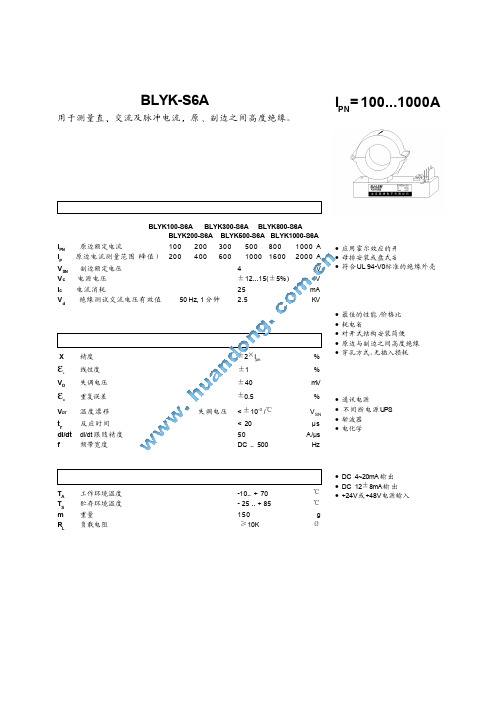
为提高传感器质量,LEM保留对此传感器随时修改的权利 恕不提前通知。
• DC 4~20mA 输出
℃
• DC 12±8mA 输 出 • +24V或+48V电源输入
℃
ቤተ መጻሕፍቲ ባይዱ
g Ω
BJ-LEM
北京莱姆电子有限公司 空港工业区B区标准厂房1号楼 北京,中国,邮编:101300
北京空港工业区B区标准厂房1号楼 网址: http: //
E-mail: BJL@
注意
± 1 mm
∅42mm
MOLEX 5045−4 2孔∅5, 孔 间 距 离 20×90mm 电位器 1:增益 电位器 2:失调
• 当原边电流沿传感器箭头方向流动时,在输出端M获得同相电
压
• 原边母排温度不得超过100°C • 原边母排充满孔径时,可获得最佳动态特性 • 原边额定电流值 IPN 及副边额定电压 VSN 可由用户指定生产
电话: + 86 (10) 80483178 传真: + 86 (10) 80484303
BLYK-S6A系 列 外 形 尺 寸 (单位:mm, 1 mm = 0.0394 英寸)
1
2
连接:
1. +15V 2. -15V 3. Vout 4. GND
机械参数
• 常规误差 • 原边穿孔 • 副边连接 • 安装 • 调整
精度 线性度 失调电压 重复误差
温度漂移 反应时间 di/dt 跟 随 精 度 频带宽度
失调电压
±2×Ipn ±1 ± 40 ±0.5
< ±10-3 /℃
< 20 50 DC .. 500
% % mV %
VSN µs A /µ s Hz
ifm电子 SM4100 磁感应流量计说明书
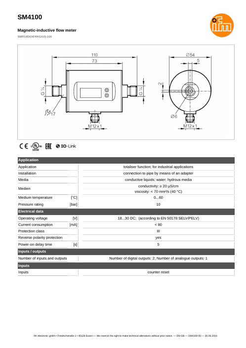
SM4100
Magnetic-inductive flow meter
SMR14DXXFRKG/US-100
Outputs Total number of outputs Output signal Electrical design Number of digital outputs Output function Max. voltage drop switching output DC Permanent current rating of switching output DC Number of analogue outputs Analogue current output Max. load Analogue voltage output Min. load resistance Pulse output Short-circuit protection Type of short-circuit protection Overload protection
SM4100
Magnetic-inductive flow meter
SMR14DXXFRKG/US-100
Connection
OUT1: OUT2: -
BK = BN = BU = WH =
colours to DIN EN 60947-5-2
switching output volumetric flow quantity monitoring Pulse output quantity meter signal output Preset counter IO-Link
[s]
Temperature monitoring
Measuring range
磁通门电流传感器工作原理图文详解
磁通门电流传感器工作原理图文详解
磁通门电流传感器是一种是以磁通门技术为基本原理,加上闭环控制在电子电路中的应用,磁通门传感器具有分辨力高、测量弱磁场范围宽、可靠、能够直接测量磁场的分量和适于在速运动系统中使用等特点。
下面本文就对磁通门电流传感器的工作原理及构成等进行详细介绍。
磁通门电流传感器工作原理磁通门传感器的工作原理是基于铁芯材料的非线性磁化特性,其敏感元件为高磁导率、易饱和材料制成的铁芯,有两个绕组围绕该铁芯:一个是激励线圈,另一个是信号线圈。
在交变激励信号fl的磁化作用下,铁芯的导磁特性发生周期性饱和与非饱和的变化,从而使围绕在铁芯上的感应线圈感应出反应外界磁场的信号。
因为磁通门传感器是利用被测磁场中高导磁率磁芯在交变磁场的饱和激励下,其磁感应强度与磁场强度的非线性关系来测量弱磁场的。
这种物理现象对被测环境磁场来说好像是一道门,通过这道门,相应的磁通量即被调制,并产生感应电动势。
利用这种现象来测量电流所产生的磁场,从而间接的达到测量电流的目的。
磁通门电流传感器原理图
二、磁通门电流传感器的构成下图是磁通门电流传感器的系统构成
磁通门电流传感器系统构成框图
电流传感器的系统框图所示。
电流所产生的的磁场在磁通门探头内经激励信号调制后,通过峰值检波和积分滤波电路产生有用的电压信号,然后经过反馈,使电流传感器工作在零磁通状态。
图1:磁通门绕组结构图。
- 1、下载文档前请自行甄别文档内容的完整性,平台不提供额外的编辑、内容补充、找答案等附加服务。
- 2、"仅部分预览"的文档,不可在线预览部分如存在完整性等问题,可反馈申请退款(可完整预览的文档不适用该条件!)。
- 3、如文档侵犯您的权益,请联系客服反馈,我们会尽快为您处理(人工客服工作时间:9:00-18:30)。
高精度电流传感器规格书
AIT1000-SG
深圳市航智精密电子有限公司
AIT1000-SG 高精度电流传感器
多点零磁通技术系统应用于现有高精度直流传感器技术之上,激励磁通闭环控制技术、自激磁通门技术及多闭环控制技术相结合,实现了对激励磁通、直流磁通、交流磁通的零磁通闭环控制,并通过构建高频纹波感应通道实现了对高频纹波的检测,从而使传感器在全带宽范围内拥有比较高的增益和测量精度。
产品图片
核心技术性能特点
◇激励磁通闭环控制技术◇原、副边隔离测量
◇自激退磁技术◇出色的线性度和准确度
◇多点零磁通技术◇极低的温漂
◇多级量程自动切换技术◇极低的零漂
◇温控补偿技术◇强抗电磁干扰能力
◇宽频带和低响应时间
应用领域
◇医疗设备:扫描仪、MRI ◇轨道交通:高速列车、地铁、有轨无轨电车◇电力:变流器、逆变器◇测试仪器仪表:功率分析仪、高精密电源◇新能源:光伏、风能◇汽车:电动汽车
◇舰船:电力驱动舰船◇航空航天:卫星、火箭
◇计量:检定与校准◇智能电网测量:发电、电池监测、中低压变电站◇工业控制:工业电机驱动、焊接、机器人、吊车、电梯、滑雪升降机
电气性能
项目符号测试条件最小值标称最大值单位原边额定直流电流I PN_DC— — ±1000 — Adc 原边额定交流电流*I PN— — 707 — Aac 原边过载电流I PM1分钟— — ±1300 Adc 工作电压V C— ±14.2 ±15 ±15.8 V 功耗电流I PWR原边额定电流±30 ±700 ±830 mA 电流变比K N输入:输出1500:1 1500:1 1500:1 — 额定输出电流I SN原边额定电流— ±0.67 — A 测量电阻R M见图1 0 1.5 3 Ω
*:指交流有效值
精度测量
项目符号测试条件最小值标称最大值单位准确度X G输入直流,25±10ºC — — 10 ppm 线性度εL— — — 2 ppm 温度稳定性T C— — — 0.1 ppm/K 时间稳定性T T— — — 0.2 ppm/month 供电抗干扰T V— — — 1 ppm/V 零点失调电流I O@25ºC — — 1(用户可调零)ppm 纹波电流I N DC-10Hz — — 0.5 ppm
动态响应时间t r di/dt=100A/us,上升至90%I PN— — 1 us 电流变化率di/dt — 200 — — A/us
频带宽度(-3dB) F — 0 — 500 kHz
零点失调电流I OT全温度范围— — ±5 μA
安全特性
项目符号测试条件数值单位隔离电压/ 原边与副边之间Vd 50Hz,1min 5 KV
瞬态隔离耐压/ 原边与副边之间Vw 50us 10 KV
爬电距离/ 原边与外壳之间dCp — 11 mm
电气间隙距离/ 原边与外壳之间dCi — 11 mm 相比漏电起痕指数CTI IEC-60112 600 V
一般特性
项目符号测试条件最小标称最大单位工作温度范围T A—-40—+85ºC 质量M—1250±20g
负载电阻使用说明
图1:负载电阻与测量电流关系图
运行状态说明
◇正常运行时,绿灯常亮:
设备上电后,当设备正常工作时,绿色指示灯常亮,D-Sub9接口的第3脚和第8脚导通。
◇电流过载或供电异常时,绿灯熄灭:
当绿灯不亮时,应该首先检查传感器的供电电源是否正常。
在供电电源正常的情况下,如果绿色指示灯熄灭,说明电流传感器处于非零磁通状态。
此时若母线输入电流幅值超过传感器的规定量程,传感器进入过载工作模式,输出电流不再与输入电流信号成等比例。
在过载模式下,传感器输出电流一直保持在最大输出状态,绿色指示灯熄灭。
当输入电流恢复到规定被测电流范围内后,传感器输出电流恢复正常,绿色指示灯常亮。
◇在过载模式下,D-Sub9接口的第3脚和第8脚断开连接。
应用连接及说明
1.D-Sub9连接端子引脚功能定义
引
脚
号
12、7345689
定义
I_Output
return
N.C Interlock(-) GND
-15V
Supply
I_Output Interlock(+)
+15V
Supply
测试说明:
通过测量流过R M的测试电流I s,或者R M两端的电压U R,
可以得到原边电流I P:
I P=K N∗I S=K N∗(U R/R M)
2.Interlock端口连接说明:
Interlock端口连接方式,根据用户实际应用,有如下两种设计方式,
分别如图A和图B所示:
图A: 传感器正常运行时低电平输出
图B:传感器正常运行时高电平输出
3
8
+VCC:
+3…+35V 传感器用户
光电耦合器工作状态如下:
联通:互感器正常工作,Vout输出电压为Gnd
断开:互感器工作不正常,Vout输出电压为Vcc
R
D-Sub9
Pin
D-Sub9
Pin
Collector
Vout
3
8 +VCC:
+3…+35V 传感器用户
光电耦合器工作状态如下:
联通:互感器正常工作,Vout输出电压为Vcc
断开:互感器工作不正常,Vout输出电压为Gnd
R
D-Sub9
Pin
D-Sub9
Pin
Collector
Vout
3.光电耦合器中引脚Vout的输出,与用户端设计电路有关,如下表所示:项目Vout 描述
图A <0.2V 传感器运行状态正常
Vcc 传感器运行状态异常,处于过载模式或供电电源异常
图B <0.2V 传感器运行状态异常,处于过载模式或供电电源异常Vcc 传感器运行状态正常
外形尺寸规格
单位:毫米(mm)
本产品为模塑件,材料为PC+PBT,外形与安装尺寸公差按照GB/T14486-2008 MT6执行。
公差等级
尺寸范围(mm)
0~3 3~6 6~10 10~14 14~18 18~24 24~30 30~40 40~50 50~65 65~80 80~100 100`120 120~140
MT6 ±0.23 ±0.26 ±0.29 ±0.33 ±0.27 ±0.41 ±0.45 ±0.50 ±0.57 ±0.65 ±0.74 ±0.84 ±0.96 ±1.10。
