多功能气体传感器模块ASxx-T
SF6多功能监测装置使用说明书

SC-COP138-B SF 6多功能监测装置使用说明书珠海三昌电器有限公司如需更多信息:请登陆 珠海三昌电器有限公司 珠海机构珠海市香洲区永田路21号706(泰坦软件园) Tel :0756-******* Fax :************需三昌公司更多信息,请致电珠海三昌电器机构沟通解决,如三昌公司版权所有!SANCHANG 标志,三昌,三昌电器、德昌、德昌电气是三昌公司在中国和/或其他国家的注册商标。
其他公司或个人不得擅自使用以上信息作为其公司、产品与服务标记的全部或部分。
目录一、 SF6在电气设备上的重要性 (2)二、系统研制的依据 (3)三、系统简介 (3)3.1系统结构图及各部件介绍 (4)3.2系统功能 (5)四、主要技术指标 (5)五、环境要求 (6)六、主要部件功能 (6)6.1SF6多功能检测装置(SF6、O2、温度、湿度四合一变送器) (6)6.2声、光警示灯(型号:NTE-1101J) (7)七、系统维护 (8)1、系统运行注意事项 (8)2、系统维护注意事项 (8)八、技术支持及售后服务 (10)1一、SF6在电气设备上的重要性上世纪60年代以来,SF6气体以其优异的绝缘和灭弧性能,在电力系统中得到广泛的应用,几乎成了中压、高压和超高压电气设备使用的唯一绝缘和灭弧介质,正因为SF6气体的大量使用,其安全性也受到了人们的广泛关注,尤其是安装在室内的SF6电气设备,监测其泄漏及室内O2的含量,从而确保作业人员的人身安全,是各级领导最关心的大事。
客观上讲,SF6气体是一种无色、无味、无臭、无毒、密度比空气重的惰性气体,不易与空气混和。
纯净的SF6对人体没有毒性,但不能维持生命。
SF6是一种简单窒息剂,暴露在O2含量小于19.5%的大气中会导致头晕、昏迷、口水增多、反应迟钝、反胃、呕吐、失去意识甚至死亡。
暴露在O2小于12%的大气中会无任何先兆地失去知觉,失去自我救护的能力。
手持式多功能烟气测试仪
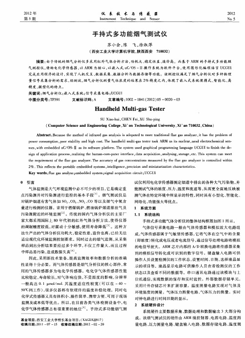
量信号采集分析 的需求, 经测试 , 烟气分析仪测量 气体 浓度 的结果在 2 %精 度之 内, 体现 了嵌入式 系统便携 式 、 能化 、 智 高
精 度 、 型化 的 特 点 。 微 关 键 词 : 气 分 析 仪 ; 入 式 系统 ; 号 采 集 电路 ; C U 烟 嵌 信 UG I
手持 式多功能气体分析仪 的整体 结构框图如 图 1 所示 。
气体信 号采集 电路 一般 由气 体传 感器 和模 拟放 大 电路 组 成, 气体传感器属 于气 敏型 传感 器 , 它将气 体 在空气 中的含 量 ( 即浓度 ) 转化成 电压或者 电流信号 , 通过信号处理 电路将模 拟 的电信 号放大 。A M芯片 内部 的 A D转换 电路将传 感器 采集 R / 到的模拟信号转 化成 可识 别 的数字信 号 。键 盘输 入 电路可 供 操作人员设置检测 仪的工作状态 , 设置 时间 、 日期 , 选择 液晶显 示的项 目等 。液 晶显示 电路 可供 操作 人员 查看 检测 仪 的工作
t e r q i me t ft e f e g s a ay e . h c u a y o a o c n r t n a u e y t efu a n lz ri c n r l d wi i h e u r e n u a n lz r T e a c rc fg s c n e t i s me s r d b h e g s a ay e s o tol t n o h l ao l e h
成 。该烟气测试 仪的硬件 由 A M 微控制 器 、 R 电源 电路 、 温度测 量 电路 、 压力测量 电路 、 盘输 入 电路 、 键 数据 存 储 电 路 、 温度测
收稿 日期 :0 1—0 21 7—1 收修改稿 日期 :0 2—0 5 2等 : 手持式多功能烟气测试仪
几种气体传感器的介绍

常见类型与用途
声表面波气体传感器有多种类型,如金属氧化物半导体型 、高分子材料型等。其中,金属氧化物半导体型传感器应 用最为广泛,主要用于检测可燃性气体、有毒有害气体等 。
声表面波气体传感器具有灵敏度高、响应速度快、稳定性 好等优点,因此在工业自动化、环境监测、安全防护等领 域得到广泛应用。
优点与局限性
热线型传感器利用加热的金属丝检测气体热导率的变化;薄膜型传感器则使用薄膜 材料作为热敏元件;干涉型传感器利用光干涉原理测量温度变化。
热导率气体传感器广泛应用于工业过程控制、环境监测、安全检测等领域,用于检 测各种有毒有害气体、可燃气体以及氧气等。
优点与局限性
热导率气体传感器具有结构简单、稳定性好、寿命长等优点,同时对某些特定气体的检测具有较高的 灵敏度和选择性。
局限性
光学气体传感器容易受到光学元件污染、光源老化等因素的影响,需要定期维护 和校准。此外,光学气体传感器的成本较高,限制了其在某些领域的应用。
04
金属氧化物半导体气体传感器
工作原理
金属氧化物半导体气体传感器利用金 属氧化物作为敏感材料,通过气体与 敏感材料发生反应,导致材料电阻发 生变化,从而检测气体浓度。
化来检测气体的浓度。
传感器通常包含光源、光检测器 和光学元件,通过测量气体对光 的吸收或散射程度,可以确定气
体的浓度。
不同的气体对光的吸收或散射程 度不同,因此传感器具有选择性 ,能够针对特定气体进行检测。
常见类型与用途
红外线气体传感器
利用红外线对不同气体的吸收特性,常用于检测 二氧化碳、甲烷等气体。
当待测气体吸附在敏感材料表面时, 敏感材料的电子结构和电阻率发生变 化,导致电阻值变化,通过测量电阻 值的变化即可推算出气体的浓度。
盛密科技7 SMART Sensor Module 传感器模块说明书
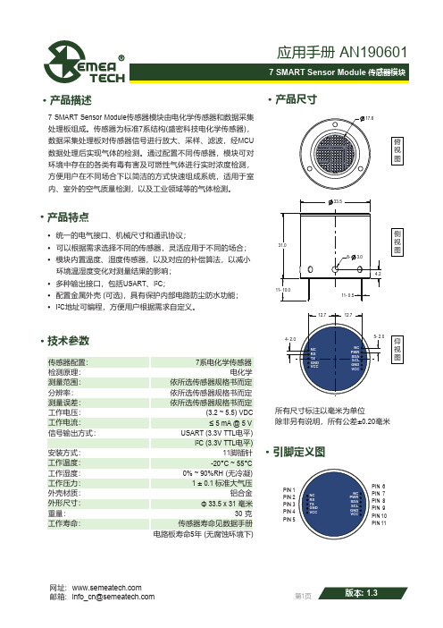
· 产品描述· 产品特点7 SMART Sensor Module 传感器模块由电化学传感器和数据采集处理板组成。
传感器为标准7系结构(盛密科技电化学传感器),数据采集处理板对传感器信号进行放大、采样、滤波,经MCU数据处理后实现气体的检测。
通过配置不同传感器,模块可对环境中存在的各类有毒有害及可燃性气体进行实时浓度检测,方便用户在不同场合下以简洁的方式快速组成系统,适用于室内、室外的空气质量检测,以及工业领域等的气体检测。
· 统一的电气接口、机械尺寸和通讯协议;· 可以根据需求选择不同的传感器,灵活应用于不同的场合;· 模块内置温度、湿度传感器,以及对应的补偿算法,以减小 环境温湿度变化对测量结果的影响;· 多种输出接口,包括USART 、I²C ;· 配置金属外壳 (可选),具有保护内部电路防尘防水功能;· I²C 地址可编程,方便用户根据需求自定义。
· 技术参数传感器配置:检测原理:测量范围:分辨率:电化学7系电化学传感器测量误差:依所选传感器规格书而定依所选传感器规格书而定依所选传感器规格书而定工作电压:工作电流:信号输出方式:USART (3.3V TTL 电平)(3.2 ~ 5.5) VDC≤ 5 mA @ 5 VI²C (3.3V TTL 电平)安装方式:工作温度:工作湿度:0% ~ 90%RH (无冷凝)11脚插针工作压力:-20°C ~ 55°C1 ± 0.1 标准大气压外壳材质:外形尺寸:重量:30 克铝合金工作寿命:Φ 33.5 x 31 毫米传感器寿命见数据手册电路板寿命5年 (无腐蚀环境下)产品尺寸·引脚定义图·PIN 1PIN 2PIN 3PIN 4PIN 5PIN PIN PIN PIN 6789PIN 10PIN 11所有尺寸标注以毫米为单位除非另有说明,所有公差±0.20毫米俯视图侧视图仰视图·USART 通信协议· 引脚定义5746321NC RX TX GND VCC NC PWR 预留针脚 (悬空)串口输入RX 串口输出TX 电源地电源 (3.2 ~ 5.5 V )预留针脚 (悬空)模块电源使能 (低电平关闭,高电平开启,内置上拉电阻) 默认上拉高电平911810SDA SCL GND VCCI²C 信号SDA (内置10kΩ上拉电阻) 默认上拉高电平I²C 信号SCL (内置10kΩ上拉电阻) 默认上拉高电平电源地电源 (3.2 ~ 5.5 V )注: 两个VCC 信号内部连通1. 串行通信参数起始位:1; 数据位:8; 停止位:1; 校验位:无; 波特率:115200 bps无特殊说明时,应答回复时间小于100ms (特殊情况请参考具体指令说明),当前命令回复前无法响应其他指令2. 帧格式 (每一通信帧的格式如下)首字节设备码功能码起始地址数据长度数据校验位(高位在前)H ID F A N D CRC16H :数据头,1Byte 固定为0x3AID :设备码,1Byte 默认为0x10,可由用户自定义F :功能码,1Byte ,例如(0x03)A :起始地址,2Bytes ,例如0x0001N :数据长度,1Byte ,以2个字节为单位,例如(0x02: 4字节)D :数据,N*2Bytes ,高位在前,例如(MSB LSB )定义为有符号短整型(signed short )CRC16:数据校验,2Bytes ,使用MODBUS_CRC16校验算法(算法详见附录1)3. 指令说明3.1 读取传感器类型上位机发送请求0x3A 0x100x010x00000x010x00000x82B0首字节设备码功能码起始地址数据长度数据校验位例:3A 10 01 00 00 01 00 00 82 B0模块接收正确数据应答首字节设备码功能码数据校验位0x3A0x100x01D(1byte数据)CRC16传感器类型代码 (十进制):0,1:无定义 2:CO 3:O2 4:H2 5:CH4 6:无 7:CO2 8:O3 9:H2S 10:SO2 11:NH3 12:CL2 13:ETO 14:HCL 15:PH3 16:无 17:HCN 18:无 19:HF 20:无21:NO 22:NO2 23:NOX 24:CLO2 25:无 26:无 27:无 28:无 29: 无 30:无31:THT 32:C2H2 33:C2H4 34:CH2O 35:无 36:无 37:无 38:无 39: CH3SH 40:C2H3CL 例:3A 10 01 0F 4C AD(十六进制0F=十进制15,即得到该传感器为PH3传感器)3.2 读取传感器数据 (单位为μg/m³)上位机发送请求首字节设备码功能码起始地址数据长度数据校验位0x3A0x100x030x00000x020x00000x7352例:3A 10 03 00 00 02 00 00 73 52模块接收正确数据应答首字节设备码功能码起始地址数据长度数据校验位0x3A0x100x030x00000x02D CRC16 D:接收到的数据,4Bytes 高位在前例:3A 10 03 00 00 02 00 00 00 5E 25 35 (D=0x0000005E=94, 得到传感器值为94μg/m³)3.3 读取传感器数据 (单位为ppb)上位机发送请求首字节设备码功能码起始地址数据长度数据校验位0x3A0x100x030x00020x020x00000x72EA 例:3A 10 03 00 02 02 00 00 72 EA模块接收正确数据应答首字节设备码功能码起始地址数据长度数据校验位0x3A0x100x030x00020x02D CRC16 D:接收到的数据,4Bytes 高位在前例:3A 10 03 00 02 02 00 00 00 4C A4 DA (D=0x0000004C=76, 得到传感器值为76ppb)备注:读取数据显示精度为1ppb,具体测试精度根据传感器不同而不同3.4 读取温度传感器数据 (单位为°C)上位机发送请求首字节设备码功能码起始地址数据长度数据校验位0x3A0x100x030x00040x010x00000x8262例:3A 10 03 00 04 01 00 00 82 62模块接收正确数据应答首字节设备码功能码起始地址数据长度数据校验位0x3A0x100x030x00040x01D CRC16 D:接收到的数据,2 Bytes 高位在前,除以100后得到温度值。
AGS02MA TVOC气体传感器产品手册说明书
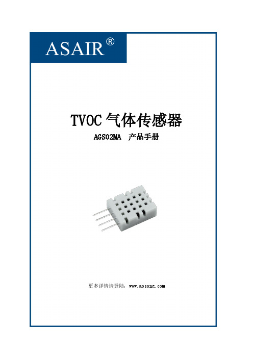
TVOC气体传感器AGS02MA 产品手册更多详情请登陆:文档修改记录AGS02MA 是一款含有已校准数字信号输出的MEMS TVOC气体传感器。
它使用专用的数字模块采集技术和气体感应传感技术,确保产品具有极高的可靠性与卓越的长期稳定性。
此款MEMS气体传感器,有低功耗高灵敏度、快速响应、高可靠性和稳定性、成本低、驱动电路简单等特点。
二、应用范围主要用于当传感器所处环境中存在污染气体,如甲醛、一氧化碳、可燃气体、酒精、氨气、硫化物、苯系蒸汽、烟雾、其它有害气体的监测,具体可应用在空气净化器、家用电器、新风机等。
传感器可检测多种有害气体。
三、产品亮点高性价比、长期稳定性好、品质卓越、超快响应、灵敏度高、响应与恢复时间快、寿命长、数字信号输出、精确校准。
四、外形尺寸(单位:mm)图1 产品尺寸图1.电气特性2.传感器特性注:符合典型精度的测量范围为0-9999ppb,拓展量程测量误差为50% F.S六、接口定义6.1 AGS02MA 引脚分配图2 AGS02MA 引脚表 1: AGS02MA 引脚分配6.2 电源引脚(VDD GND)AGS02MA 的供电电压范围为3.3V - 5.5V。
6.3 串行时钟输入(SCL)SCL引脚上电必须保持高电平直到进行I2C通信开始,否则会引起I2C通讯不良。
当I2C通信时SCL 用于微处理器与AGS02MA 之间的通讯同步。
6.4 串行数据(SDA)SDA引脚为三态结构,用于读、写传感器数据。
具体的通信时序,见通信方式的详细说明。
注:SDA引脚与SCL引脚必须接一个1KΩ~10KΩ的上拉电阻到VDD。
七、I2C总线通信协议AGS02MA传感器采用标准I2C通信协议,适应多种设备,协议使用两根数据线:串行数据总线(SDA)与串行时间总线(SCL),两根数据线需要接上拉电阻到VDD。
多个传感器设备可以共享总线;但是只能有一个主机设备可以出现在总线上。
传感器I2C地址为0x1A,写指令为0x34,读指令为0x35。
气体传感器ppt课件

Va Vg
Va:气敏元件在洁净空气中工作时,负载电阻上的电压输出;
Vg:气敏元件在规定浓度被测气体中工作时,负载电阻的电压输出
15
(3)气敏元件的分辨率 表示气敏元件对被测气体的识别(选择)以及对干扰气体的抑制 能力。气敏元件分辨率S表示为
S Vg Vg Va Vgi Vgi Va
Va—气敏元件在洁净空气中工作时,负载电阻上的输出电压; Vg—气敏元件在规定浓度被测气体中工作时,负载电阻上的电压 Vgi—气敏元件在i种气体浓度为规定值中工作时,负载电阻的电压
(1) MOS二极管气敏器件
MOS二极管气敏元件制作过程是在P型半导体硅片上,利 用热氧化工艺生成一层厚度为50~100nm的二氧化硅(SiO2)层, 然后在其上面蒸发一层钯(Pd)的金属薄膜,作为栅电极,如图 14-5(a)所示。
M(Pd)
SiO2 P—Si
C
Ca
氢气中
空气中
Cs
O
V
(a)
(b)
14.1 概述
14 气 体 传 感 器
气体传感器是将被测气体浓度转换为与其一定关系的电量 输出的装置或器件。
气体传感器是用来检测气体类别、浓度和成分的传感器。
由于气体种类繁多, 性质各不相同,不可能用一种传感器检 测所有类别的气体,按构成气体传感器材料可分为半导体和非 半导体两大类。目前实际使用最多的是半导体气体传感器。
的电阻值)称为加热电阻,用RH表示。直热式的加热电阻值一
般小于5Ω;旁热式的加热电阻大于20Ω。 气敏元件正常工作所需的加热电路功率,称为加热功率,
用PH表示。一般在(0.5~2.0)W范围。
(6)气敏元件的恢复时间 表示在工作温度下,被测气体由该元件上解吸的速度,一般从气
六合一甲基丙烯酸甲酯气体传感器变送模块

10-35VDC、5VDC±5%、220VDC(可选择一种)
分辨率、精度
待定
重量
0.3kg左右
六合一体参数
项目内容
具体参数
产品名称
六合一甲基丙烯酸甲酯气体传感器变送模块
采样方式
扩散式、泵吸式。了解详情请咨询厂家
检测气体
6种不同的气体自由组合
工作温度
有传感器特性和产品结构决定
测量范围
具体量程请咨询厂家
工作湿度
10%~95%RH,无冷凝(湿度>90%RH,凝露可选配过滤器)
其它参数检测
可加
通讯方式
有线:RS-485、RS-422
无线:WIFI、Zigbee、LORA、433M、800M、GPRS/3G/4G。可选择其中一种
显示
带显和不带线都有
显示单位
ppm、mg/m3、ppb、pphm、%VOL、%LEL
功耗
欢迎来电咨询
使用寿命
由功能和检测气体种类决定
结构尺寸
长X宽X高:126X91X40
检测原理
电化学、催化、PID、红外、荧光法
工作压力
由传感器原理和产品结构决定。具体请来电咨询!
PM2.5检测
选配0-500微克/立方米
温度测量范围
区间可选精度待定(选配功能)
PM10检测
选配0-500微克/立方米
湿度测量范围
0-100%RH精度±3%(选配功能)
温湿度补偿
选配
温湿度检测
选配温度(-60℃~+120℃)、湿度(0-100%RH)
炜盛 红外SF6气体传感器模组说明书

红外SF6气体传感器模组说明书V1.0郑州炜盛电子科技有限公司Zhengzhou Winsen Electronic Technology Co.,LTD感谢您使用郑州炜盛电子科技有限公司系列产品,当您准备使用本产品时请务必仔细阅读本说明。
并按照所提供的有关操作步骤进行,使您能充分享受我公司提供的服务。
请妥善保管本手册,以便在您日后需要时能及时查阅、获得帮助。
版权声明:本手册版权属郑州炜盛电子科技有限公司所有,未经书面许可,本手册任何部分不得复制、翻译、存储于数据库或检索系统内,也不可以电子、翻拍、录音等任何手段及方式进行传播。
郑州炜盛电子科技有限公司秉承科技进步原则,不断致力于产品改进、技术创新的服务理念。
在此,本公司保留任何产品改进而不预先通知的权利。
如果用户不依照本手册说明擅自拆解、更换传感器内部件,由此产生的问题由用户负责。
产品及产品颜色、款式请以购买的实物为准。
郑州电子科技有限公司通讯地址:郑州市高新技术开发区金梭路299号邮编:450001服务电话:*************/60932966/60932977传真号码:*************微信号:winsensor服务信箱:*******************目录1概述 (4)2技术参数 (5)3.结构尺寸图(单位:MM) (6)4.信号输出 (6)5安装尺寸图(单位:MM) (11)6维护保养应注意的事项 (11)1概述SF6气体作为绝缘介质和灭弧气体在电力设备普遍使用,特别在高压断路器、变压器、互感器、电容器、避雷器、熔断器等有广泛应用。
发生泄漏,设备压力降低,绝缘能力降低;污染和破坏大气环境,增加温室效应;在低层空间积聚,导致工作人员大脑缺氧,甚至快速窒息等事故;局部放电、高温等因素影响下,SF6气体会产生如SF4、SF2、SOF2等高毒分解物。
此产品是一款采用NDIR红外吸收检测原理的气体传感器模组,根据SF6气体在10.5um的吸收量确定浓度大小。
贝斯特多功能气体报警控制器说明书

贝斯特多功能气体报警控制器说明书
(1)报警器探头主要是接触燃烧气体传感器的检测元件,由铂丝线圈上包氧化铝和黏合剂组成球状,其外表面附有铂、钯等稀有金属。
因此,在安装时一定要小心,避免摔坏探头。
(2)报警器的安装高度一般应在160—170cm,以便于维修人员进行日常维护。
(3)报警器是安全仪表,有声、光显示功能,应安装在工作人员易看到和易听到的地方,以便及时消除隐患。
(4)报警器的周围不能有对仪表工作有影响的强电磁场(如大功率电机、变压器)。
(5)被测气体的密度不同,室内探头的安装位置也应不同。
被测气体密度小于空气密度时,探头应安装在距屋顶30cm外,方向向下;反之,探头应安装在距地面30cm处,方向向上。
家用可燃气体报警器安装位置图
家用可燃气体报警器安装位置:
探测器应安装在气体易泄漏场所,具体位置应根据被检测气体相对于空气的比重决定。
当被检测气体比重大于空气比重时,探测器应安装在距离地面(30~60)cm处,且传感器部位向下。
当被检测气体比重小于空气比重时,探测器应安装在距离顶棚(30~60)cm处,且传感器部位向下。
为了正确使用探测器及防止探测器故障的发生,请不要安装在以下位置:
1. 直接受蒸汽、油烟影响的地方;
2. 给气口、换气扇、房门等风量流动大的地方;
3. 水汽、水滴多的地方(相对湿度:≥90%RH);
4. 温度在-40℃以下或55℃以上的地方;
5. 有强电磁场的地方。
凯朔达 PCS 恒温扑控 ком合气体传感器说明书
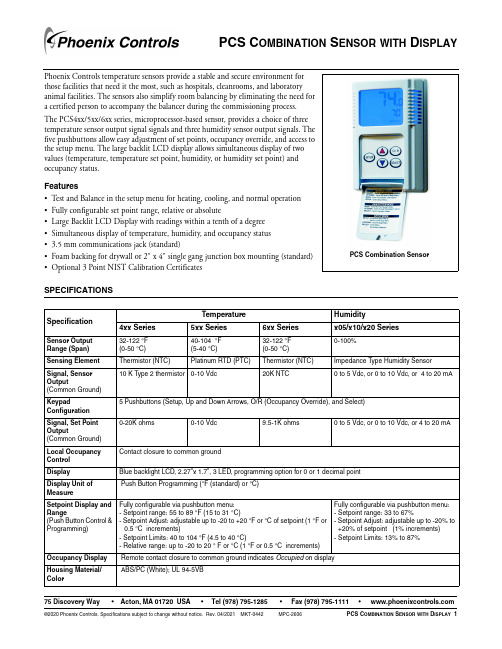
PCS C OMBINATION S ENSOR WITH D ISPLAY75 Discovery Way•Acton, MA 01720 USA •Tel (978) 795-1285•Fax (978) 795-1111•©2020 Phoenix Controls. Specifications subject to change without notice. Rev. 04/2021 MKT-0442MPC-2606PCS C OMBINATION S ENSOR WITH D ISPLAY1Phoenix Controls temperature sensors provide a stable and secure environment for those facilities that need it the most, such as hospitals, cleanrooms, and laboratory animal facilities. The sensors also simplify room balancing by eliminating the need for a certified person to accompany the balancer during the commissioning process.The PCS4xx/5xx/6xx series, microprocessor-based sensor, provides a choice of three temperature sensor output signal signals and three humidity sensor output signals. The five pushbuttons allow easy adjustment of set points, occupancy override, and access to the setup menu. The large backlit LCD display allows simultaneous display of two values (temperature, temperature set point, humidity, or humidity set point) and occupancy status.Features •Test and Balance in the setup menu for heating, cooling, and normal operation •Fully configurable set point range, relative or absolute•Large Backlit LCD Display with readings within a tenth of a degree •Simultaneous display of temperature, humidity, and occupancy status •3.5 mm communications jack (standard)•Foam backing for drywall or 2" x 4" single gang junction box mounting (standard)•Optional 3 Point NIST Calibration CertificatesSPECIFICATIONSSpecificationTemperatureHumidity4xx Series5xx Series6xx Seriesx05/x10/x20 SeriesSensor Output Range (Span)32-122 °F (0-50 °C)40-104 °F (5-40 °C)32-122 °F (0-50 °C)0-100%Sensing Element Thermistor (NTC)Platinum RTD (PTC)Thermistor (NTC)Impedance T ype Humidity Sensor Signal, Sensor Output(Common Ground)10 K Type 2 thermistor 0-10 Vdc20K NTC0 to 5 Vdc, or 0 to 10 Vdc, or 4 to 20 mAKeypadConfiguration 5 Pushbuttons (Setup, Up and Down Arrows, O/R (Occupancy Override), and Select)Signal, Set Point Output(Common Ground)0-20K ohms0-10 Vdc9.5-1K ohms0 to 5 Vdc, or 0 to 10 Vdc, or 4 to 20 mALocal Occupancy Control Contact closure to common groundDisplay Blue backlight LCD, 2.27”x 1.7”, 3 LED, programming option for 0 or 1 decimal point Display Unit of MeasurePush Button Programming (°F (standard) or °C)Setpoint Display and Range(Push Button Control & Programming)Fully configurable via pushbutton menu:- Setpoint range: 55 to 89 °F (15 to 31 °C)- Setpoint Adjust: adjustable up to -20 to +20 °F or °C of setpoint (1 °F or0.5 °C increments)- Setpoint Limits: 40 to 104 °F (4.5 to 40 °C)- Relative range: up to -20 to 20 ° F or °C (1 °F or 0.5 °C increments)Fully configurable via pushbutton menu:- Setpoint range: 33 to 67%- Setpoint Adjust: adjustable up to -20% to +20% of setpoint (1% increments)- Setpoint Limits: 13% to 87%Occupancy Display Remote contact closure to common ground indicates Occupied on display Housing Material/ColorABS/PC (White); UL 94-5VBPCS Combination Sensor2 PCS C OMBINATION S ENSOR WITH D ISPLAY MKT-0442 MPC-2606 ©2020 Phoenix Controls. Specifications subject to change without notice. Rev. 04/2021DIMENSIONSTest & BalanceSettings(Push Button Control) 40 °F (4.4 °C), 72 °F (22.2 °C), and 104 °F (40 °C)0%, 50%, and 100%Communication Jack 3.5 mm Stereo Jack (Ring, Tip, Shield)Operating Range 35-122 °F (1.5-50 °C), 0-95% Relative Humidity Non-Condensing Storage Range -4-131 °F (-20-60 °C), 0-95% Relative Humidity Non-Condensing Reference Resistance 10K ohm @ 77 °F (25 °C)1K ohm @ 32 °F (0 °C)20K ohm @ 77 °F (25 °C)N/AAccuracySensor Output Accuracy: +/- 1.0 °F (+/- 0.56 °C): LCD Display Accuracy +/- 1.5 °F due to Rounding2% from 10 to 95% RH @ 77 °F (25 °C)Dissipation Constant N/AResponse Time 10 seconds nominal for a 63% step increase (room-hot water)11 seconds nominal for a 63% step decrease (room-ice water)20 seconds for a step of 46%-96%45 seconds for a step of 98%-47%Stability < 1% after 1000 hours at 212 °F (100 °C)N/A< 1% after 1000 hours at 212 °F (100 °C)< 2% over 5 years Supply Voltage +18 to 40 Vdc (NOTE: Use of PVC400-HW is required for LON applications)Power Consumption < 0.65 VA (x05 and x10 Series), < 4 VA (x20 Series)Product Dimensions (L x W x D) 4.56" (115.82 mm) x 3.0" (76.2 mm) x 1.45" (36.75 mm)Product Weight 0.35 lbs (0.162 kg)NIST Certification (6 Points)61 °F (16 °C), 72 °F (22.5 °C), and 82 °F (28 °C)20%, 50%, and 80% @ 72 °F (22 °C)Regulatory ComplianceSpecificationTemperatureHumidity4xx Series5xx Series6xx Seriesx05/x10/x20 SeriesWEEE Directive 2012/19/ECWaste Electrical and Electronic Equipment directiveAt the end of the product life dispose of the packaging and product in a corresponding recycling centre. Do not dispose of the unit with the usual domestic refuse. Do not burn the product.EU Contact Address:Pittway Tecnologica Srl Via Caboto 19/334147 Trieste TS Italy©2020 Phoenix Controls. Specifications subject to change without notice. Rev. 04/2021 MKT-0442 MPC-2606PCS C OMBINATION S ENSOR WITH D ISPLAY 3ORDERING GUIDEValid Catalog NumbersOUTPUT FORMULAS AND TABLESFor output formulas and complete sensor output tables, see MKT-0474 Sensor Outputs and T ables .PHX-COMBINATION-SENSOR (10K-2 Temperature Output)PHX-COMBINATION-SENSOR (0-10VDC Temperature Output)PHX-COMBINATION-SENSOR (20KTemperature Output)Catalog Number without CalibrationCertificate Catalog Number with 6 Point CalibrationCertificate Catalog Number without CalibrationCertificate Catalog Number with 6 Point CalibrationCertificate Catalog Number without CalibrationCertificate Catalog Number with 6 Point CalibrationCertificate PCS405-R-DOP PCS405-R-DOP-06PCS505-R-DOP PCS505-R-DOP-06PCS605-R-DOP PCS605-R-DOP-06PCS405-R-DHOP PCS405-R-DHOP-06PCS505-R-DHOP PCS505-R-DHOP-06PCS605-R-DHOP PCS605-R-DHOP-06PCS410-R-DOP PCS410-R-DOP-06PCS510-R-DOP PCS510-R-DOP-06PCS610-R-DOP PCS610-R-DOP-06PCS410-R-DHOP PCS410-R-DHOP-06PCS510-R-DHOP PCS510-R-DHOP-06PCS610-R-DHOP PCS610-R-DHOP-06PCS420-R-DOP PCS420-R-DOP-06PCS520-R-DOP PCS520-R-DOP-06PCS620-R-DOP PCS620-R-DOP-06PCS420-R-DHOPPCS420-R-DHOP-06PCS520-R-DHOPPCS520-R-DHOP-06PCS620-R-DHOPPCS620-R-DHOP-06。
气体传感器翻译
连接与测试 将气体传感器过滤器插入模块前方的狭槽。 气体传感器本质上是电阻性器件而不是两极 性器件,因此不用担心将其插反。无论安装时的方向如何都可正常工作。 4 引脚接头可以方便地将气体传感器插入面包板或 SIP 槽。 4 个引脚的定义如下图所示。 与像基板这样的 5V 微处理器相连是最直接的方法,只需要两个 I/O 口;一个输入口检测报 警信号,另一个输出口用来控制内部热源。 与一个像 Propeller 板这样的 3.3V 微处理器相连时,需要用到一个 3.9 千欧(10 千欧也 可)的电阻来将 ALR 输出与 Propeller 板输入口相连。为了便于 Propeller 板控制接头开关输 出(HSW)需要一个 NPN 型三极管,例如 2N3904 和一个 1 千欧电阻。接线图如下所示。
*HSW 线由一个 10 千欧电阻上拉至 5V。 注意:传感器震动时可能会发出咯咯声——这是正常现象。 工作原理 该气体传感器模块采用 Hanwei 电子的气体传感器。当内置加热元件被激活时,传感器 对特定的气体传声响应, 其电阻随元件周围的空气中的气体含量的增加而线性减小。 该电阻 是由传感器内部和电位器 R3 共同构成的分压电阻的一部分。分压电阻的输出就是两个 LT1013 双通道运算放大器集成电路的输入信号。运算放大器 A 被配置成具有单位增益的缓 冲器,用来给 TP1(+)和 TP2(-)提供一个零载荷测试点的信号电压。该信号电压输入给 运算放大器 B,运算放大器 B 被配置成比较器,其反相输入端的参考电压由 R4 的断路电平
引脚定义 引脚 E1 E2 E3 E4 TP1 TP2 TP3 TP4 名称 ALR HSW +5V GND 测试点 1+ 测试点 2测试点 3+ 测试点 4功能 输出到微控制器的警报信号 微控制器的热输入信号 +5V 直流电源 接地 传感器缓冲输出 接地 由 R4 设置的信号电平 接地 电平 0V/5V 0V/浮动 5V 0V 0V-5V 0V 0V-5V 0V
利用气体传感器设计气体测量实验方案

利用图表、曲线等形式将处理后的数据呈 现出来,便于观察和分析实验结果。
04
实验结果与分析
气体浓度测量数据展示
传感器响应曲线
通过气体传感器对目标气体进行连续测量,得到传感器响应曲线。该曲线可以 反映气体浓度随时间的变化情况。
气体浓度测量值
根据传感器响应曲线,可以计算出气体浓度的测量值。通过与标准气体浓度进 行比较,可以评估传感器的准确性。
03
实验方法与步骤
搭建气体测量系统
选择合适的气体传感器
根据实验需求,选择对目标气体敏感、响应快、稳定性好的气体 传感器。
设计气路系统
确保气体能够均匀、稳定地流过传感器,避免产生涡流或死角,同 时方便更换气体样本。
搭建数据采集系统
将气体传感器与数据采集卡或微处理器连接,实现数据的实时采集 、转换和存储。
02
实验设备与材料
气体传感器选型及参数
传感器类型
根据实验需求选择适合的气体 传感器,如电化学传感器、催 化燃烧传感器、红外传感器等
。
量程
根据实验所需测量的气体浓度 范围选择合适的传感器量程。
精度
选择具有高精度的传感器,以 确保实验结果的准确性。
响应时间
选择响应时间短的传感器,以 便及时反映气体浓度的变化。
微型化和便携化
随着微纳加工技术的发展,气体传感器将越来越微型化和便携化 ,为现场实时监测和应急响应提供便利。
THANKS
感谢观看
06
实验总结与展望
本次实验成果总结
气体传感器性能验证
成功验证了所选用气体传感器的灵敏度、响应时间和恢复时间等关 键性能指标,为后续实验提供了可靠的数据支持。
气体浓度测量实验
通过搭建实验系统,实现了对多种气体浓度的准确测量,并验证了 测量结果的稳定性和重复性。
Sensirion SGP30 气体传感器数据手册说明书

Datasheet SGP30Sensirion Gas Platform▪ Multi-pixel gas sensor for indoor air quality applications ▪ Outstanding long-term stability▪ I 2C interface with TVOC and CO 2eq output signals ▪ Very small 6-pin DFN package: 2.45 x 2.45 x 0.9 mm 3 ▪ Low power consumption: 48 mA at 1.8V ▪ Tape and reel packaged, reflow solderableBlock DiagramFigure 1 Functional block diagram of the SGP30.Product SummaryThe SGP30 is a digital multi-pixel gas sensor designed for easy integration into air purifier, demand-controlled ventilation, and IoT applications. Sensirion’s CMOSens ® technology offers a complete sensor system on a single chip featuring a digital I 2C interface, a temperature controlled micro hotplate, and two preprocessed indoor air quality signals. As the first metal-oxide gas sensor featuring multiple sensing elements on one chip, the SGP30 provides more detailed information about the air quality.The sensing element features an unmatched robustness against contaminating gases present in real-world applications enabling a unique long-term stability and low drift. The very small 2.45 x 2.45 x 0.9 mm 3 DFN package enables applications in limited spaces. Sensirion’s state-of-the-art production process guarantees high reproducibility and reliability. Tape and reel packaging, together with suitability for standard SMD assembly processes make the SGP30 predestined for high-volume applications.1Sensor Performance 1.1Gas Sensing PerformanceAccuracy ethanol signalFigure 2Typical and maximum accuracy tolerance in % of measured value at 25°C, 50% RH and typical VDD. The sensors have been operated for at least 24h before the characterization. Accuracy H2 signalFigure 3Typical and maximum accuracy tolerance in % of measured value at 25°C, 50% RH and typical VDD. The sensors have been operated for at least 60h before the characterization.1 Exposure to ethanol and H2 concentrations up to 1000 ppm have been tested. For applications requiring the measurement of higher gas concentrations please contact Sensirion.2 ppm: parts per million. 1 ppm = 1000 ppb (parts per billion)3 90% of the sensors will be within the typical accuracy tolerance, >99% are within the maximum tolerance.4 The long-term drift is stated as change of accuracy per year of operation.5 Test conditions: operation in 250 ppm Decamethylcyclopentasiloxane (D5) for 200h simulating 10 years of operation in an indoor environment.Long-term drift Ethanol signalmeasuredLong-term drift H2 signalFigure 5Typical and maximum long-term drift in % of measuredvalue at 25°C, 50% RH and typical VDD. The sensors have beenoperated for at least 60h before the first characterization.Figure 6 Simplified version of the functional block diagram (compare Figure 1) showing the signalpaths of the SGP30.1.3Recommended Operating ConditionsThe sensor shows best performance when operated within recommended normal temperature and humidity range of5 – 55 °C and 4 –20 g/m3, respectively. Long-term exposure (operated and not operated) to conditions outside therecommended range, especially at high humidity, may affect the sensor performance. Prolonged exposure to extreme conditions may accelerate aging. To ensure stable operation of the gas sensor, the conditions described in the document SGP Handling and Assembly Instructions regarding exposure to exceptionally high concentrations of some organic or inorganic compounds have to be met, particularly during operation. Please also refer to the Design-in Guide for optimal integration of the SGP30.2Electrical Specifications6 A 20% higher current is drawn during 5ms on V DDH after entering the measurement mode.Table 5 Absolute minimum and maximum ratings.Please contact Sensirion for storage, handling and assembly instructions.7 If VDD and VDDH are not shorted, it is required that VDD is always powered when VDDH is powered. Otherwise, the sensor might be damaged.85 Timing Specifications5.1 Sensor System TimingsThe timings refer to the power up and reset of the ASIC part and do not reflect the usefulness of the readings.Parameter Symbol ConditionMin. Typ. Max. Unit Comments Power-up time t PU After hard reset, V DD ≥V POR - 0.4 0.6 ms - Soft reset timet SRAfter soft reset-0.40.6ms-Table 6 System timing specifications.5.2 Communication TimingsParameter Symbol Conditions Min. Typ. Max. Units Comments SCL clock frequencyf SCL-- 400 kHz - Hold time (repeated) START conditiont HD;STA After this period, the first clock pulse is generated 0.6 --µs-LOW period of the SCL clock t LOW - 1.3 - - µs - HIGH period of the SCL clockt HIGH- 0.6 - - µs - Set-up time for a repeated START condition t SU;STA - 0.6 - - µs - SDA hold time t HD;DAT - 0 - - ns - SDA set-up time t SU;DAT - 100 - - ns - SCL/SDA rise time t R - - - 300 ns - SCL/SDA fall time t F - - - 300 ns - SDA valid timet VD;DAT - - - 0.9 µs - Set-up time for STOP condition t SU;STO - 0.6 - - µs - Capacitive load on bus lineC B-400pF-Table 7 Communication timing specifications.Figure 8 Timing diagram for digital input/output pads. SDA directions are seen from the sensor. Bold SDA lines are controlled by the sensor; plain SDA lines are controlled by the micro-controller. Note that SDA valid read time is triggered by falling edge of preceding toggle.SCL70% 30%t LOW1/f SCL t HIGHt Rt FSDA70% 30%t SU;DATt HD;DATDATA INt RSDA70% 30% DATA OUTt VD;DATt F6Operation and CommunicationThe SGP30 supports I2C fast mode. For detailed information on the I2C protocol, refer to NXP I2C-bus specification8. All SGP30 commands and data are mapped to a 16-bit address space. Additionally, data and commands are protected with a CRC checksum to increase the communication reliability. The 16-bit commands that are sent to the sensor already include a 3-bit CRC checksum. Data sent from and received by the sensor is always succeeded by an 8-bit CRC.In write direction it is mandatory to transmit the checksum, since the SGP30 only accepts data if it is followed by the correct checksum. In read direction it is up to the master to decide if it wants to read and process the checksum.The I2C master can abort the read transfer with a XCK followed by a STOP condition after any data byte if it is not interested in subsequent data, e.g. the CRC byte or following data bytes, in order to save time. Note that the data cannot be read more than once, and access to data beyond the specified amount will return a pattern of 1s.6.3Measurement CommandsThe available measurement commands of the SGP30 are listed in Table 10.Air Quality SignalsThe SGP30 uses a dynamic baseline compensation algorithm and on-chip calibration parameters to provide two complementary air quality signals. Based on the sensor signals a total VOC signal (TVOC) and a CO 2 equivalent signal (CO 2eq) are calculated. Sending an “Init_air_quality” command starts the air quality measurement. After the “Init_air_quality” command, a “Measure_air_quality” command has to be se nt in regular intervals of 1s to ensure proper operation of the dynamic baseline compensation algorithm. The sensor responds with 2 data bytes (MSB first) and 1 CRC byte for each of the two preprocessed air quality signals in the order CO 2eq (ppm) and TVOC (ppb). For the first 15s after the “Init_air_quality” command the sensor is in an initialization phase during which a “Measure_air_quality” command returns fixed values of 400 ppm CO 2eq and 0 ppb TVOC.The SGP30 also provides the possibility to read and write the baseline values of the baseline correction algorithm. This feature is used to save the baseline in regular intervals on an external non-volatile memory and restore it after a new power-up or soft reset of the sensor. The command “Get_baseline” ret urns the baseline values for the two air quality signals. The sensor responds with 2 data bytes (MSB first) and 1 CRC byte for each of the two values in the order CO 2eq and TVOC. These two values should be stored on an external memory. After a power-up or soft reset, the baseline of the baseline correction algorithm can be restored by sending first an “Init_air_quality” command followed by a “Set_baseline” command with the two baseline values as parameters in the order as (TVOC, CO 2eq). An example implementation of a generic driver for the baseline algorithm can be found in the document SGP30_driver_integration_guide .A new “Init_air_quality” command has to be sent after every power -up or soft reset.Sensor Raw SignalsThe command “Measure_raw_signals” is i ntended for part verification and testing purposes. It returns the sensor raw signals which are used as inputs for the on-chip calibration and baseline compensation algorithms as shown in Figure 6. The command performs a measurement to which the sensor responds with 2 data bytes (MSB first) and 1 CRC byte (see Figure 9) for 2 sensor raw signals in the order H2_signal (s out_H2) and Ethanol_signal (s out_EthOH ). Both signals can be used to calculate gas concentrations c relative to a reference concentration c ref byln (c c ref ⁄)=s ref −s outawith a = 512, s ref the H2_signal or Ethanol_signal output at the reference concentration, and s out = s out_H2 or s out = s out_EthOH .Humidity CompensationThe SGP30 features an on-chip humidity compensation for the air quality signals (CO 2eq and TVOC) and sensor raw signals (H2-signal and Ethanol_signal). To use the on-chip humidity compensation an absolute humidity value from an external humidity sensor like the SHTxx is required. Using the “Set_humidity” comm and, a new humidity value can be written to the SGP30 by sending 2 data bytes (MSB first) and 1 CRC byte. The 2 data bytes represent humidity values as a fixed-point 8.8bit number with a minimum value of 0x0001 (=1/256 g/m 3) and a maximum value of 0xFFFF (255 g/m 3 + 255/256 g/m 3). For instance, sending a value of 0x0F80 corresponds to a humidity value of 16.50 g/m 3 (16 g/m 3 + 128/256 g/m 3).After setting a new humidity value, this value will be used by the on-chip humidity compensation algorithm until a new humidity value is set using the “Set_humidity” command. Restarting the sensor (power-on or soft reset) or sending a value of 0x0000 (= 0 g/m 3) sets the humidity value used for compensation to its default value (0x0B92 = 11.57 g/m 3) until a new humidity value is sent. Sending a humidity value of 0x0000 can therefore be used to turn off the humidity compensation.Feature SetThe SGP30 features a versioning system for the available set of measurement commands and on-chip algorithms. This so called feature se t version number can be read out by sending a “Get_feature_set_version ” command. The sensor responds with 2 data bytes (MSB first) and 1 CRC byte (see Table 9). This feature set version number is used to refer to a corresponding set of available measurement commands as listed in Table 10.Table 9 Structure of the SGP feature set number. Please note that the last 5 bits of the product version (bits 12-16 of the LSB) are subject to change. This is used to track new features added to the SGP multi-pixel platform.Measure TestThe command “Measure_test” which is included for integration and production line testing runs an on-chip self-test. In case of a successful self-test the sensor returns the fixed data pattern 0xD400 (with correct CRC).9 The «Measure_Test» command is intended for production line testing and verification only. It should not be used after having issued an “Init_air_quality” command. For the duration of the «Measure_Test» command, the sensor is operated in measurement mode with a supply current as specified in Table 3. After the command, the sensor is in sleep mode.Table 13 I2C CRC properties.6.7Communication Data SequencesFigure 10 Laser marking on SGP30. The pin-1 location is indicated by the keyhole pattern in the light-colored central area. The bottom line contains a 4-digit alphanumeric tracking code8.3Package OutlineFigure 12 Recommended landing pattern.9Tape & Reel Package11Important Notices11.1Warning, Personal InjuryDo not use this product as safety or emergency stop devices or in any other application where failure of the product could result in personal injury. Do not use this product for applications other than its intended and authorized use. Before installing, handling, using or servicing this product, please consult the data sheet and application notes. Failure to comply with these instructions could result in death or serious injury. If the Buyer shall purchase or use SENSIRION products for any unintended or unauthorized application, Buyer shall defend, indemnify and hold harmless SENSIRION and its officers, employees, subsidiaries, affiliates and distributors against all claims, costs, damages and expenses, and reasonable attorney fees arising out of, directly or indirectly, any claim of personal injury or death associated with such unintended or unauthorized use, even if SENSIRION shall be allegedly negligent with respect to the design or the manufacture of the product.11.2ESD PrecautionsThe inherent design of this component causes it to be sensitive to electrostatic discharge (ESD). To prevent ESD-induced damage and/or degradation, take customary and statutory ESD precautions when handling this product.See application note “ESD, Latchup and EMC” for more information.11.3WarrantySENSIRION warrants solely to the original purchaser of this product for a period of 12 months (one year) from the date of delivery that this product shall be of the quality, material and workmanship defined in SENSIRION’s published specifications of the product. Within such period, if proven to be defective, SENSIRION shall repair and/or replace this product, in SENSIRION’s discretion, free of charge to the Buyer, provided that:∙notice in writing describing the defects shall be given to SENSIRION within fourteen (14) days after their appearance;∙such defects shall be fou nd, to SENSIRION’s reasonable satisfaction, to have arisen from SENSIRION’s faulty design, material, or workmanship;∙the defective product shall be returned to SENSIRION’s factory at the Buyer’s expense; and∙the warranty period for any repaired or replaced product shall be limited to the unexpired portion of the original period.This warranty does not apply to any equipment which has not been installed and used within the specifications recommended by SENSIRION for the intended and proper use of the equipment. EXCEPT FOR THE WARRANTIES EXPRESSLY SET FORTH HEREIN, SENSIRION MAKES NO WARRANTIES, EITHER EXPRESS OR IMPLIED, WITH RESPECT TO THE PRODUCT. ANY AND ALL WARRANTIES, INCLUDING WITHOUT LIMITATION, WARRANTIES OF MERCHANTABILITY OR FITNESS FOR A PARTICULAR PURPOSE, ARE EXPRESSLY EXCLUDED AND DECLINED. SENSIRION is only liable for defects of this product arising under the conditions of operation provided for in the data sheet and proper use of the goods. SENSIRION explicitly disclaims all warranties, express or implied, for any period during which the goods are operated or stored not in accordance with the technical specifications.SENSIRION does not assume any liability arising out of any application or use of any product or circuit and specifically disclaims any and all liability, including without limitation consequential or incidental damages. All operating parameters, including without limitation recommended parameters, must be validated for each customer’s applications by customer’s technical experts. R ecommended parameters can and do vary in different applications. SENSIRION reserves the right, without further notice, (i) to change the product specifications and/or the information in this document and (ii) to improve reliability, functions and design of this product.Copyright© 2017 by SENSIRION.CMOSens® is a trademark of Sensirion.All rights reserved.12Headquarters and SubsidiariesSensirion AG Laubisruetistr. 50CH-8712 Staefa ZH Switzerlandphone: +41 44 306 40 00 fax: +41 44 306 40 30 ****************** Sensirion Inc., USAphone: +1 312 690 5858*********************Sensirion Korea Co. Ltd.phone: +82 31 337 7700~3*********************www.sensirion.co.kr Sensirion Japan Co. Ltd.phone: +81 3 3444 4940*********************www.sensirion.co.jpSensirion China Co. Ltd.phone: +86 755 8252 1501*********************Sensirion Taiwan Co. Ltdphone: +886 3 5506701****************** To find your local representative, please visit /distributors。
智能红外甲烷气体传感器(MH-741A)说明书

Intelligent Infrared Methane Gas Sensor(Model: MH-741A)ManualVersion: 3.3Valid from: May 1st, 2014Zhengzhou Winsen Electronics Technology Co., Ltd.StatementThis manual copyright belongs to Zhengzhou Winsen Electronics Technology Co., LTD. Without the written permission, any part of this manual shall not be copied, translated, stored in database or retrieval system, also can’t spread through electronic, copying, record ways.Thanks for purchasing our product. In order to keep customers using it better and reduce the faults caused by misuse, please read the manual carefully and operate it correctly in accordance with the instructions. If users disobey the terms or remove, disassemble, change the components inside of the sensor, we shall not be responsible for the loss.The specific such as color, appearance, sizes etc., please in kind prevail.We are devoting ourselves to products development and technical innovation, so we reserve the right to improve the products without notice. Please confirm it is the valid version before using this manual. At the same time, users’ comments on optimized using way are welcome.Please keep the manual properly, in order to get help if you have questions during the usage in the future.Zhengzhou Winsen Electronics Technology CO., LTD.MH-741A Infrared CH4 Gas Sensor1. Product DescriptionMH-741A is a universal type intelligent sensor todetect CH4 gas,taking advantage of non-dispersiveinfrared (NDIR) principle. With high selectivity, nooxygen dependence, high performance and longlifespan features, MH-741A also has built-intemperature compensation feature. MH-741A is acompact and high-performance sensor based oninfrared absorption of gas detection technology,micro-machining and sophisticated circuit design.2. FeaturesHigh sensitivity, high resolution, low power consumptionOutput method: UART, analog voltage signal, etc.Quick responseTemperature compensation, excellent linear outputExcellent stability, Long lifespanAnti-poisons, anti-vapor interferenceDetect combustible gas concentration matching with flame-proof marked detector in area 1&2 explosive environments which mix of ⅡA, ⅡB, ⅡC and T1-T6 flammable gases, vapors and air 3. ApplicationWidely used for industrial field instrumentation, industrial-process control and safety protection 4. Specification Table 1 Technical IndexProduct Model MH-741AGas Detected Flammable GasWorking Voltage 4.5 V ~ 5.5V DCAverage Current < 100mAInterface Level 3.3VMeasurement Range 0~100%VOL optional (view table 2)Output Signal IIC0.4-2V DCWarm-up Time 3minResponse Time T90 < 30sWorking Temperature -40℃ ~ 70℃Working Humidity 0 to 95%RH, non-condensing Dimension Φ44×61mmWeight 350gLifespan >5 yearsEx-marking Ex d ⅡC T6 GbProtected Class IP65Table 2 Measurement Range and AccuracyDetected Gas MeasurementRangeAccuracy RemarkMethane(CH4) 0~5%VOL 0.01%VOL Temperature compensation Methane(CH4) 0~10%VOL 0.01%VOL Temperature compensation Methane(CH4) 0~100%VOL 0.1%VOL Temperature compensation 5. Structural DrawingFigure 1 Structural Drawing of SensorFigure 2 Pin DefinitionPin DescriptionPad1V in (input voltage 4.5V~5.5V)Pad4GNDPad5V out (0.4~2V)Pad2IIC(SCL) clockPad3IIC(SDA) dataPad6, Pad7, Pad8Pad10, Pad11, Pad12Reserved, do not connectTable 3 Definition of Pin6. Application CircuitFigure 3 Application Circuit7. Explanation7.1 Analogue Voltage OutputInput 5V voltage to Win Pin, GND Pin connect power ground and Vout Pin connect input side of ADC, then warm-up the sensor, the Vout side will output a voltage value which stands for the gas concentration, while output voltage range 0.4V~2V stands for gas concentration 0~FS. If it found introuble in self-inspection process, the output voltage of sensor is 0V.Figure 4 Analogue Voltage Output7.2 Digital OutputInput 5V voltage to Win Pin, GND Pin connect power ground, CLK side of user’s communication interface connect CLK side of detector while SDA side connect SDA side of detector, then the detector will read the value of gas concentration directly through the IIC of the sensor (The pull-up resistor of user’s SCL and SDA signal lines must be no more than 10k to ensure the normal work of the communication interface), no need to calculate. 7.2.1 Communication ProtocolInfrared sensorInfrared sensorInfrared sensorDisplayUserMicro controllerRelayIsolationMH-741A is communicated through IIC bus. The module works basing IIC slave mode and can connects to external MCU, module address: 0x55, write operation address: 0xAA, read operation address: 0xAB. Every frame number data contains 10 bytes. Different host orders lead to different data and the last byte of data is the proof test value. The SCL clock frequency is recommend less than 10K.1) Device AddressAddress format: Highest seven digits are the module add of the sensor(0x55), the least significant digit is SDIR, 0 stand for Reading, 1 stand for Writing.Table 4: Address FormatIIC communicationWrite address: 0xAA, Read address: 0xAB2) Bus DescriptionIIC interface protocol is a special bus signal protocol, is composed of 3 parts - Start(S), Stop(P) and binary data, as shown below. At start,SCL is high,SDA is at falling edge.Aftter that,send the slave add.After the seven add digits is the control read&write digits,choose the read&write operation as above picWhen the slave device recognizes the corresponding add information,it sends a responsive signal to main device and SDA is pulled down at the ninth clock cycle.At stop,SCL keeps high level,SDA is at rising edge.Figure 5 IIC Sequence Chart3) CommandEvery frame number data of IIC communication command contains 10 bytes. Different host orders lead to different data and the last byte of data is the proof test value. Table 5 Command List0x96 Gas Concentration 0xA0 Calibrate zero point (ZERO ) 0xAACalibrate span point (SPAN )A7 A6 A5 A4 A3 A2 A1 W/R1 0 1 0 1 0 1 0/1Gas Concentration Reading1 0x96 Gas Concentration ReadingSend0 1 2 3 4 5 6 7 8 9 Command -- -- -- -- -- -- -- --CheckCode 0x96 0x00 0x00 0x00 0x00 0x00 0x00 0x00 0x00 0x6AEXP. 96 00 00 00 00 00 00 00 00 6AReturn0 1 2 3 4 5 6 7 8 9 ModuleStatusHighDensityLowDensityHighRangeLowRangeCheckCodeEXP. ReturnGas concentration= high density *256 + low density Calibrate Zero1 0xA0 Gas Concentration ReadingSend0 1 2 3 4 5 6 7 8 9 Command-- -- -- -- -- -- -- --CheckCode 0xa0 0x00 0x00 0x00 0x00 0x00 0x00 0x00 0x00 0x60EXP. A0 00 00 00 00 00 00 00 00 60Return 0 1 2 3 4 5 6 7 8 9 -- -- -- -- -- -- -- -- ---- -- -- -- -- -- -- -- --EXP. No value returnCalibrate Span1 0xAA Gas Concentration ReadingSend0 1 2 3 4 5 6 7 8 9 CommandSPAN Value -- -- -- -- -- --CheckCode 0xaaHighByteLowByte0x00 0x00 0x00 0x00 0x00 0x00 0xbbEXP. AA 13 88 00 00 00 00 00 00 BB (Eg. calibrate 5000ppm, HEX:0x1388)Return 0 1 2 3 4 5 6 7 8 9 -- -- -- -- -- -- -- -- ---- -- -- -- -- -- -- -- --EXP. No value return7.2.2 Calibrate and CalculateThe checksum = (invert (byte0 +... + 8)) + 1For example, Gas Concentration ReadingCommand SentByte0 Byte1 Byte2 Byte3 Byte4 Byte5 Byte6 Byte7 Byte8 Byte9 Command - - - - - - - - CheckValue 0x96 0x00 0x00 0x00 0x00 0x00 0x00 0x00 0x00 0x6AA. Add all the bytes together except byte 00x96 + 0 + 0 + 0 + 0 + 0 + 0 + 0 + 0 = 0x96B. Get the value from step A, then invert it.0xff – 0x96 = 0x69C. Plus one based on the value of step B0x69 + 0x01 = 0x6A7.2.3 Example ProgramC Language Calibrate & Calculate and Routinechar getCheckSum(char *packet){char i, checksum;for( i = 1; i < 9; i++){checksum += packet[i];}checksum = 0xff – checksum;checksum += 1;return checksum;}8. Notes For Maintenance8.1 The sensor should be calibrated regularly. Recommended cycle time is once per 6 months.8.2 Do not use the sensor in the high dusty environment for long time.8.3 Please use the sensor with correct power supply.Zhengzhou Winsen Electronics Technology Co., LtdAdd.: NO.299 Jinsuo Road, National Hi-Tech Zone,Zhengzhou, 450001 ChinaTel.: 0086-371-67169097Fax: 0086-371-60932988E-mail:*******************Website:。
甲基丙烯酸甲酯气体报警传感器变送模块
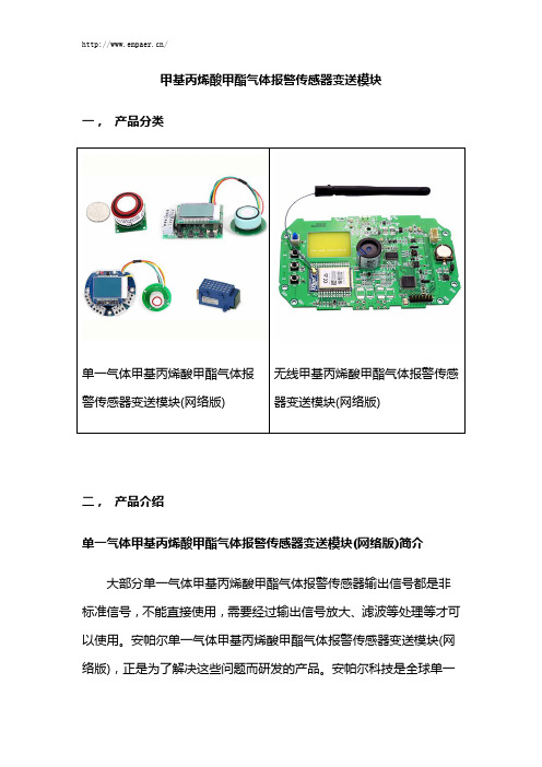
甲基丙烯酸甲酯气体报警传感器变送模块一,产品分类单一气体甲基丙烯酸甲酯气体报警传感器变送模块(网络版) 无线甲基丙烯酸甲酯气体报警传感器变送模块(网络版)二,产品介绍单一气体甲基丙烯酸甲酯气体报警传感器变送模块(网络版)简介大部分单一气体甲基丙烯酸甲酯气体报警传感器输出信号都是非标准信号,不能直接使用,需要经过输出信号放大、滤波等处理等才可以使用。
安帕尔单一气体甲基丙烯酸甲酯气体报警传感器变送模块(网络版),正是为了解决这些问题而研发的产品。
安帕尔科技是全球单一气体甲基丙烯酸甲酯气体报警传感器变送模块(网络版)种类最齐全的公司,不论从量程选择、结构尺寸、供电方式、信号输出、功能特点等安帕尔科技基本上都有非常丰富的产品供您选择。
公司成立到现在一直都在为各行业、各环境的客户OEM和ODM各种各样的单一气体甲基丙烯酸甲酯气体报警传感器变送模块(网络版)。
如您有特殊的单一气体甲基丙烯酸甲酯气体报警传感器变送模块(网络版)需要开发,请咨询我公司。
多年的技术经验和强大的技术实力您放心的选择保障!无线甲基丙烯酸甲酯气体报警传感器变送模块(网络版)简介安帕尔科技的无线甲基丙烯酸甲酯气体报警传感器变送模块(网络版)具有无线输出方式多样,产品种类齐全的特点;WIFI、Zigbee、LORA、433M、800M、GPRS/3G/4G等各种无线输出方式随意选择,可以满足市场上各种客户对无线现场使用的要求。
如您需要开发它其功能的无线甲基丙烯酸甲酯气体报警传感器变送模块(网络版),请咨询安帕尔科技。
我们公司有多年的研发经验和强大的技术实力可以满足您的需求,请您放心的选择我们。
市面上大部分甲基丙烯酸甲酯气体传感器输出信号都是非标准信号,不能直接使用,需要经过输出信号放大、滤波等处理等才可以使用,安帕尔无线甲基丙烯酸甲酯气体报警传感器变送模块(网络版)正是为了解决这个问题而研发的产品。
三,产品特点单一气体甲基丙烯酸甲酯气体报警传感器变送模块(网络版)特点★产品质量可靠、性能稳定:10多年的气体报警传感器变送模块研发经验,保证了安帕尔单一气体甲基丙烯酸甲酯气体报警传感器变送模块(网络版)质量、性能的可靠性。
多功能气体检测仪combimate3中文说明书

文档从互联网中收集,已重新修正排版,word格式支持编辑,如有帮助欢迎下载支持。
Combi-Mate 3个人多气体监测仪使用手册提升海上安全性安全信息:•使用前请阅读并理解所有手册上操作部分的指示•不要更换零部件,可能会影响安全和保障•注意所有列在部件和本手册上的警告和指导•注意气体被检出时的健康安全保障程序和疏散程序•确认您明白屏幕显示的内容和警报•如果产品没有正常工作,请读问题排除指导或致电百威航运服务公司•确认合格的服务人员更换了传感器和操作系统•确认维修和测定都根据手册上的步骤实施对有害环境下使用者的特别指示以下指导适用于这些型号的设备:Combi-Mate 3 = Baseefa 05ATEX0187 Combi-Mate 3 = IECEx BAS 05.0059 1.铭牌如下:2.此设备可用于1区、2区,易燃气体组IIA,IIB和IIC,温度和蒸汽条件T1,T2,T3和T4。
3.此设备的工作环境温度范围为–20°C ——+55°C(即-4°F——+131°F)。
在此温度范围外不可使用。
4.设备达到Baseefa认证的IEC 60079-0,60079-1,60079-11,EN61779-5标准,符合健康安全要求。
达到气体探测标准EN50054,EN50057,EN61779-1,EN61779-4和EN50104,以及Lloyds Register认证的EN50207。
5.设备的维修和更换气体传感器应由生产商进行,或者遵循适用的操作规范。
6.如果设备接触到强放射性物质,使用者有责任采取恰当措施,保护设备不受损害,以确保设备的保护功能完好无损。
7.可充电电池只能在无害(安全)环境下充电,充电需连接到百威航运服务公司指定的充电器。
8.此设备不能在含氧量超过21%的环境下使用。
区域划分:1区:在常规操作环境下可能存在易燃气体、蒸汽或液体的区域为1区。
基于单片机的燃气预警装置的设计
基于单片机的燃气预警装置的设计近年来,燃气事故时有发生,严重威胁人们的生命和财产安全。
为了避免燃气事故的发生,基于单片机的燃气预警装置应运而生。
本文将介绍基于单片机的燃气预警装置的设计。
一、硬件设计本文设计的燃气预警装置的硬件主要由单片机、MQ-2传感器、蜂鸣器和LCD液晶显示屏组成。
1. 单片机本文采用STC89C52RC单片机,是一种高性能的8位单片机,具有512字节的RAM和32K字节的Flash存储器。
2. MQ-2传感器MQ-2传感器是一种多功能气体传感器,可以检测可燃气体、烟雾和一氧化碳等气体。
当检测到有害气体时,输出电压会发生变化。
3. 蜂鸣器当检测到可燃气体或有毒气体时,蜂鸣器会发出声音,提醒用户采取措施。
4. LCD液晶显示屏当检测到气体时,LCD液晶显示屏上会显示气体种类和浓度,方便用户了解气体情况。
二、软件设计本文采用Keil μVision5软件进行编程。
主要分为如下几个部分。
1. 初始化部分对单片机和MQ-2传感器进行初始化操作。
2. 读取传感器数值部分从MQ-2传感器中读取气体浓度数值,并根据数值判断是否存在可燃气体或有毒气体。
3. 控制部分当检测到有害气体时,蜂鸣器会发出声音,提醒用户采取措施。
同时,通过LCD液晶显示屏显示气体种类和浓度。
三、使用说明将本燃气预警装置放置在易燃、易爆、有毒环境内。
当检测到有害气体时,蜂鸣器会发出声音,提醒用户采取措施,同时,LCD液晶显示屏会显示气体种类和浓度。
四、总结本文介绍了基于单片机的燃气预警装置的设计,该装置可以检测可燃气体、烟雾和一氧化碳等气体,并进行报警提示。
该装置具有灵敏度高、准确性高、便携性好等优点,能够有效地预防燃气事故的发生。
AST压力传感器

型号大类别产品描述AST4000AST 4000采用整体不锈钢感应元件,可应用在各种要求结构坚固、使用寿命长,以及对不锈钢无腐蚀及损坏的领域,以实现其优秀和长期的测压性能。
为方便机械和电器连接,AST 4000提供了多种螺纹的压力接口及电信号输出以供选择。
AST4100AST 4100是一种小型而价廉的不锈钢压力传感器。
AST 4100兼容的液压和气压范围可由0至10000 PSI,应用范围十分广阔。
AST 4100可选择10mV/V输出,或其它放大信号输出。
AST4200面板专用压力传感器为了简化压力传感器在控制面板上应用安装,美国传感器技术公司推出了AST4200贴板式压力传感器。
传统方法只涉及由传感器到面板的转接器,而创新的AST 4200是穿过面板安装从而消除了可能的液体渗漏途径。
UL/cUL508认证美国AST系列压力AST4900AST 4900是专用于测量高纯净度液体和气体、被测介质与传感器及电信号之间分离的压力传感器。
传感器无填充油、无焊接及O形圈,并对介质接口进行过特殊处理从而消除了传感器对系统污染的风险。
整体的设计同时有利于延长使用寿命,增强抗冲击抗震的能力,并且即使在极端条件下,仍可保持长期的稳定性。
AST4300AST 4300是一种可在危险环境中使用的、被测介质与传感器及电信号之间分离的不锈钢压力传感器。
除了坚固的结构和优秀的性价比之外,AST 4300还是多种危险环境应用压力测量的首选。
AST4310AST 4310是一种可在危险环境中使用的、被测介质与传感器及电信号之间分离的、现场可调式压力传感器。
该传感器的两个调节点由维通O形圈保护,可以调节零点和满度(全量程压力的)±5%偏差。
另外,为简化安装后的调节,AST4310在传感器机身上专门提供了两个调节孔。
AST 4310拥有宽范围螺纹接口,多种输出信号,要求各种调节能力的压力测量的首选。
危险场所使用AST4400AST 4400是具有多种选择的、被测介质与传感器及电信号之间分离的不锈钢传感器。
- 1、下载文档前请自行甄别文档内容的完整性,平台不提供额外的编辑、内容补充、找答案等附加服务。
- 2、"仅部分预览"的文档,不可在线预览部分如存在完整性等问题,可反馈申请退款(可完整预览的文档不适用该条件!)。
- 3、如文档侵犯您的权益,请联系客服反馈,我们会尽快为您处理(人工客服工作时间:9:00-18:30)。
气体检测传感器模块ASxx-T
产品示意图
产品特性
ASxx-T采用标准4系/7系电化学气体传感器、红外气体传感器、催化燃烧气体传感器、输出信号TTL、RS485等、针对集成商低成本应用用户设计、只要有4系/7系传感器均可通过本模块运算、校准、现有的CO、O3、SO2、CH2O、O2、CxHx传感器已经广泛应用于各类监控、监测解决方案,本安型设计、可带电热插拔,简化的外围电路、个性化的数据标定、校准程序,可自由切换传感器探头(同型号、以便传感器寿命达到极限时自由更换),同时支持氧电池,2pin电极式等类似封装,与标准内径防爆式探测头完美兼容。
应用领域
智能家居、报警器、通风系统、新风换气系统、气体监控系统、环境气体控制器、新风控制器、空气质量检测仪、气体检测仪、固定式气体变送器等
规格参数
检测原理电化学、催化燃烧、红外等4系或7系传感器
检测范围0~500ppm(最大1000ppm);
分辨率0.01、0.1、1ppm
预热时间3分钟
相对误差≦±3%
数据漂移使用周期内小于2%
使用温度范围-20~65℃
使用寿命电化学、催化燃烧2年,红外8-10年
供电5VDC
输出TTL串口、RS485
尺寸φ37*25mm
引脚定义(参考电路板)
V:电源正(5V)
B:TTL发送或485B
A:TTL接收或485A
G:公共地
T:调试引脚请悬空
D;W;C为lcd引脚,驱动ASLCD1.0显示模块
封装尺寸
检测参数及选型表
检测气体型号检测量程精度分辨率
名称串口协议(Modbus Rtu )
1、通讯串口设置(TTL):波特率9600,无校验,8数据位,1停止位。
2、万能通讯命令16进制:00030000000185DB (设备地址可用此找回)
3、寄存器描述(支持03和06命令字)使用规范
1.传感器不是普通的电子元器件,需要仔细防护,这一点用户必须重视。
寄存器
40001(010300000001840A)
存储检测气体浓度值(分辨率与量程见检测参数及选型表)
40018(010*********D9C5)寄存器锁定位(修改其它参数前需先将此位改
为十进制24)断电自动锁定
40019波特率存储位
40020(010*********F9CE)地址改为2,请先修改40018
串口通讯地址(默认为1)
2.长期暴露在高浓度的化学蒸汽中或灰尘中将会致使传感器的读数产生漂移。
3.在生产、使用及运输过程中,要保证传感器远离高湿、高温、高浓度的化学溶剂。
4.要避免使用挥发性胶水、粘性胶带、不干胶贴纸,或具有挥发性的包装材料,如发泡塑料袋、泡沫塑料等。
5.生产场合需要保持通风
6.按引脚说明图连接电路
7.使用或嵌入其它结构过程中需充分保证与外界空气的完全接触。