Ficoll 400裂解液(20% wv)
苯红ого香达400无线温度传输器说明书

SmartLine STIW400 Wireless Temperature DI Transmitter Specification 34-SW-03-11, April 2022Model STIW400•Up to 4 channels of inputs for T/C’s or mV.•Up to 2 channels of RTD’s or 3-wire resistance.•Up to 4 channels for discrete input or 2-wireresistance.IntroductionSmartLine Wireless Temperature continues theevolution of Honeywell’s wireless transmitter productoffering and provides the latest critical advancementsto support industrial automation users’ desire to expandwireless use for monitoring and control.With over 14 years of industrial wireless experience,the SmartLine Wireless Temperature builds upon andis compatible with the current XYR 6000 productporfotlio. Similar to the XYR 6000 wireless transmitter,the SmartLine Wireless product line is part of theHoneywell OneWireless™ system and is ISA100 -ready.The SmartLine Wireless Temperature transmitterenables customers to obtain data and createinformation from remote and hazardous measurement locations without the need to run wires, where running wire is cost prohibitive and/or the measurement is in a hazardous location. Without wires, transmitters can be installed and operational in minutes, quickly providing information back to your system.The previous generation transmitters primarily were applied to monitoring applications but experienced users know that Honeywell’s wireless products are as reliable, secure, and safe as their wired counterparts. With this knowledge, users are now looking for wireless transmitters for use in specific control applications.Figure 1 — SmartLine Wireless Temperature DITransmitterSmartLine Wireless introduces a step change in performance and most notably, performance suitable for control. SmartLine Wireless performance is improved in these ways:•Fast ½ second publication rate.•Higher radio range coverage.•More powerful 4dBi integral antenna.•Smarter local display with more localdiagnostics and radio signal and qualityindicators.•More input channels and types than earlier.XYR 6000 Wireless Pressure Transmitter Differential Pressure Models 2SmartLine Wireless Temperature retains the following desirable features from the XYR 6000 product offering:•Mesh or non-mesh configuration within each transmitter.•Generic, off-the-shelf lithium ion battery.•Two “D” size batterie s for longer life.•Choice of over-the-air or local provisioning (network security join key).•Over-the-air firmware upgrade capability.•Unique, encrypted provisionng key delivered from the factory.•Remote and integral antenna options.•24 VDC power option.•Publication rates of 1, 5, 10, or 30 seconds, plus new selections of ½ seconds and 1, 15,30, 60 minutes.•Transmitter range (integral antenna) of 1150’ (350 m) under ideal conditions.The STIW400 is a high-performance Temperature transmitter featuring performance over a wide of temperature configurations and applications.The SmartLine family is also fully tested and compliant with Experion® PKS providing the highest level of compatibility assurance and integration capabilities. SmartLine easily meets the most demanding application needs for Temperature measurement applications. SmartLine Wireless FeaturesLocal and over-the-air provisioning capability:All Honeywell wireless devices feature a secure method to join the local wireless network, also known as provisioning. SmartLine Wireless transmitters feature two methods to provision a transmitter onto the network which are eitherby using a handheld device to locally communicate through the IR interface or remotely using the over-the-air function. The over-the-air function is managed by the OneWireless gateway, Wireless Device Manager (WDM). Over-the-air firmware updates:Once joined as a member of your OneWireless network, the WDM can download new transmitter firmware releases to each SmartLine Wireless transmitter over the wireless network. Locating and accessing the transmitter locally is not required thus saving time and keeping your personnel in safe environments.Mesh and non-mesh capability: All SmartLine Wireless transmitters can be configured to operate in either a mesh network or a star (non-mesh) network. The configuration is specific to each wireless transmitter and thus the network can consist of a mixture of meshing and non-meshing devices. Non-meshing is desirable for deterministic communications which is preferred for control. Transmission power setting:To comply with local and regional requirements, SmartLine Wireless transmitters are set at the factory to the maximum transmission power setting allowed for the country of use.Non-proprietary battery:Sourcing lithium thionyl chloride batteries is much simpler since SmartLine Wireless utilizes commercial off-the-shelf batteries. Please see the list of approved battery manufacturers later in this specification. Batteries are housed in an IS-approved battery compartment making battery changes safe and easy. Backward compatibility:SmartLine Wireless transmitters can join existing OneWireless networks and interoperate with existing XYR 6000 wireless transmitters or otherISA100 Wireless compliant transmitters or networks.OneWireless Network FeaturesThe core of the Honeywell wireless solution is the OneWireless Network which consists a gateway, access point(s), and field routers.The Wireless Device Manager (WDM) serves as the gateway function and in this role, manages the communication from the wireless field devices to the process control application. Typically, the WDM connects logically to the process control network (Level 2 or wireless DMZ). As the wireless network manager, the WDM provides easy access to the entire wireless network through a browser-based user interface. The Honeywell WDM can manage devices communicating over theISA100 Wireless protocol and the Wireless HART protocol.The ability to deploy redundant WDMs improves the reliability ensuring no loss of process data which is a requirement for control applications.The Field Device Access Point (FDAP) serves in two roles in the OneWireless network infrastructure, which are: 1) access point, and 2) field router. As an access point, the FDAP directly connects to the WDM via Ethernet LAN cable. More than one access point is permitted and, when more than one is present, it ensures dual path for communications into the WDM from the field devices. As a field router, the FDAP located in the field would communicate to the FDAP acting as an access point. Using the FDAP as a router is more efficient than using field devices as routers since FDAPs are line powered devices whereas field devices are typically battery powered, and the FDAP offers greater range. The meshing capability of FDAPs allows flexibility in the setup of the wireless network to fit the requirements for wireless network performance, in terms of reliable communications, performance, and future growth. The choice of non-meshing network may be desirable for reduced communication latencies with a FDAP serving as a field router.Wireless Specifications*Actual range will vary depending on antennas, cables and site topography.SpecificationsOperating Conditions1 The Ambient Limits shown are for Ordinary Non-Hazardous locations only. Refer to the Hazardous Locations Approvals section for the Ambient Limits when installed in Hazardous Locations.Remote Antenna CablesRemote Antennas8 dBi Omnidirectional Antenna14 dBi Directional AntennaPerformance SpecificationsPerformance under Rated Conditions** Field Calibration available for increased accuracy applications.** Performance specifications are based on reference conditions of 25°C (77°F), 10 to 55% RH. *** Default values; user configurable.Physical Specifications1 Add 8.0 pounds (3.6 Kg) to any model equipped with the stainless steel housing option (Model Selection Guide Table IV selection M or N).STIW400 ISA100.11a Compliant InputsAny combination of sensor type inputs is allowed. The input channels can be configured for the following input types by using the OneWireless User Interface with the corresponding device descriptor file:Selecting any RTD / 3-Wire Ohm Resistance input on Channel 1 and on Channel 3 renders Channel 2's and Channel 4’s input terminals unavailable.The transmitter measures the analog signal from temperature sensors, discrete inputs, millivolt values or ohm values and transmits a digital output signal proportional to the measured value for direct digital communications with systems.The discrete input channels support voltage-free floating contacts. Maximum ON contact resistance is 200 ohms. Minimum OFF contact resistance is 300 ohms. Discrete Input threshold values are user configurable.The Process Variable (PV) is available for monitoring and alarm purposes. The cold junction temperature is also available for monitoring. Available PV update rates are 1, 5, 10, or 30 seconds, plus new selections of ½ sec (Refer User Manual for applicable conditions) and 1, 15, 30, 60 minutes and are set using the Wireless Builder. Slower update rates extend battery life.Input Types and RangesSTIW400 TEMPERATURE TRANSMITTER CONNECTIONST/C or mV or DI or 2 Wire ResistancePV1PV2PV3PV43 Wire RTD or ResistancePV1PV33 Wire RTD or ResistancePV1PV3PV4T/C or mV or DI or 2 Wire ResistanceMounting and DimensionsReference Dimensions:Figure 2 — Examples of typical mounting positionsFigure 3 — Examples of typical mounting positionsFigure 4 – STIW400 Informational and dimensional drawingFigure 5 — Typical mounting dimensions for STIW400Figure 6 — Typical mounting dimensions for STIW400Hazardous Locations ApprovalsRefer to control drawing 50136129, in the user manual #34-SW-25-04, for intrinsically safe installation details.Transmitter Options(indicated selection code is shown)ISA100 Wireless Release Selections (A or B)OneWireless R2xx represents the previous releases whereas R3xx is the current release. A OneWireless system with R3xx firmware can host R2xx and R3xx devices. Please select the option to match the targeted OneWireless system.Remote Antenna and Cables (M or D)The user can select one of the optional remote antennas listed. The selection of the antenna option automatically includes the remote antenna adapter.To complete the option selection, one of the remote antenna cables (1, 2, or 3) must also be selected.Lightning (Surge) Diverter and Cables (1, 2, or 3)The lightning surge diverter options includes the surge diverter and cable. The diverter features Type N connections (female) on both ends. The remote antenna adapter is not included.Remote Antenna Adapter (A)This option provides an adapter to be inserted into the opening where the integral antenna normally connects. The adapter is designed to connect to a remote antenna that the user supplies. It features a female Type N connection.Destination Country (CA, EU, or US)This selection sets the transmission power at the factory to comply with the installation country location.Mounting Brackets (1, 3, 5, or 7)The angle mounting bracket is available in either zinc-plated carbon steel or 316 stainless steel and is suitable for horizontal or vertical mounting on a two-inch (50 millimeter) pipe, as well as wall mounting.An additional flat mounting bracket is also available in carbon steel and 316 stainless steel for two-inch (50 millimeter) pipe mounting.Tagging (Option 1 or 2)The choice of 1 or 2 stainless steel wired-on tags is available. Each tag can accommodate additional data of up to 4 lines of 28 characters. The number of characters includes spaces.Note that the standard nameplate on the meter body contains the serial number and body-related data.Model Selection GuideModel Selection Guides are subject to change and are inserted into the specifications as guidance only.For more informationTo learn more about SmartLine Transmitters, visit Or contact your Honeywell Account ManagerProcess Solutions Honeywell1250 W Sam Houston Pkwy S Houston, USA, TX 77042Honeywell Control Systems LtdHoneywell House, Skimped Hill Lane Bracknell, England, RG12 1EB34-SW-03-11 April 2022©2022 Honeywell International Inc.Shanghai City Centre, 100 Jungi Road Shanghai, China 20061Sales and ServiceFor application assistance, current specifications, ordering, pricing, and name of the nearest Authorized Distributor, contact one of the offices below.ASIA PACIFICHoneywell Process Solutions, Phone: + 800 12026455 or +44 (0) 1202645583 (TAC) hfs-tac-*********************AustraliaHoneywell LimitedPhone: +(61) 7-3846 1255 FAX: +(61) 7-3840 6481 Toll Free 1300-36-39-36 Toll Free Fax: 1300-36-04-70China – PRC - Shanghai Honeywell China Inc.Phone: (86-21) 5257-4568 Fax: (86-21) 6237-2826SingaporeHoneywell Pte Ltd.Phone: +(65) 6580 3278 Fax: +(65) 6445-3033South KoreaHoneywell Korea Co Ltd Phone: +(822) 799 6114 Fax: +(822) 792 9015EMEAHoneywell Process Solutions, Phone: + 800 12026455 or +44 (0) 1202645583Email: (Sales)*************************** or (TAC)*****************************AMERICASHoneywell Process Solutions, Phone: (TAC) (800) 423-9883 or (215) 641-3610(Sales) 1-800-343-0228Email: (Sales)*************************** or (TAC)*****************************。
Flex Gateway G2 用户手册说明书

User Manual Flex Gateway G204 / 25 / 2018Revision 21. CPS Data & Controls System Description (3)1.1) Standard Inverter Modbus Communication Card (4)1.2) Optional Flex Gateway Communications Card (5)1.3) Chint Power Systems Connect (CPS Connect) Mobile App (6)1.4) CPS Service Portal (6)2. Interface & Indicators (7)3. Installation Options (9)3.1) Inverter Wirebox (9)3.2) External Installation (10)4. Site Activation (11)4.1) Download the APP : CPS Connect ( Chint Power Systems Connect) (11)4.2) Connect the Flex Gateway (12)4.3) Status of Wifi Module (13)4.4) Test and Save the Configuration (14)4.5) Activate Flex Gateway (15)5. Hardware Datasheet of Flex Gateway 2.0 (18)1. CPS Data & Controls System DescriptionChint Power Systems (CPS) offers a complete inverter data acquisition and controls solution for its customers in North and Central America. Our platform aims to:Enable advanced inverter data communications & controlReduce communications HW cost and installation laborSupport seamless 3rd party integrationReduce O&M costs and improve field performanceEnable customers with direct data accessThe system comprises of four key components:Standard Inverter Modbus CommunicationsOptional Flex Gateway Communications CardChint Power Connect (CPS Connect) Mobile AppCPS Service Web Portal1.1) Standard Inverter Modbus Communication CardEach CPS three phase string inverter (Models SCA23KTL-X, SCA28KTL-X, SCA36KTL-X, SCA50KTL-X, SCA60KTL-X, SCA100KTL-X, SCA125KTL-X) ships standard, at no charge, with Modbus communications capability. This built in communications capability offers both data read access to approximately 32 parameters, depending on inverter model, but also advanced and remote controls of as many as 56 parameters.To enable inverter level data access, each inverter must be connected to a 3rd party monitoring gateway via standard RS-485 twisted shield pair Modbus daisy chain. Modbus wiring instructions are provided in the respective inverter product manuals.Standard built-in communicationsin every inverter wireboxApplication guides and Modbus data maps are available at the website athttps:///downloads.htmlor by contacting CPS applications engineering at 1-855-584-7168.1.2) Optional Flex Gateway Communications CardThe optional Flex Gateway card offers a site level inverter communications capability to customers and to CPS Service. This card works as a Modbus master gateway (site level) and connects to the inverter Modbus daisy chain network.The Flex Gateway enables the following additional features above standard Modbuscommunications:Remote inverter firmware upgrade support by CPS ServiceRemote diagnostics by CPS ServiceBroadcast controls commands to speed up control loops for advanced applications like power quality management or zero export requirementsDirect customer data from the Flex Gateway via a programmable Ethernet XML Sunspec Data Exchange connection for customers who want to manage their owndata directlyPass thru Modbus communications to a 3rd party gatewayOptional Flex Gateway1.3) Chint Power Systems Connect (CPS Connect) Mobile AppThe CPS Connect mobile application is used to wirelessly program and setup the Flex Gateway in the field. It is intended to be used by installers, operations, maintenance and other site personnel to program the communications equipment. The app is available at the Apple iOS store and at the Google store for Android based devices.Each Flex Gateway ships with a Wi-Fi Module that connects to the Flex Gateway to create a local Wi-Fi network. Once connected to the Flex Gateway, all inverters on the Modbus daisy chain network can be programmed.1.4) CPS Service PortalThe CPS Service Portal is a web based interface intended for use by the CPS service team. This advanced portal enables remote diagnostics and FW management of connected systems.2. Interface & IndicatorsSwitchSwitchSwitch Switch3. Installation Options3.1) Inverter Wirebox3.2) External Installation4. Site Activation4.1) Download the APP: CPS Connect (Chint Power Systems Connect)Scan the following QR-code to complete APP download and installation by using the mobile phones that can access the Internet.and Web Portal.4.2) Connect the Flex GatewayOpen the APP – CPS Connect and choose Flex Gateway. Click Wi-Fi Setting and switch to Wi-Fi configuration of mobile phone.Ensure to connect the SSID starts with CPLK-XXXXXXX.4.3) Status of Wi-Fi Module4.4) Test and Save the ConfigurationClick Test to check the default configuration.The APP will send the default configuration to the Flex Gateway and start testing. Click Save the Config to ensure all settings take effect.Auto start to scan the address in turn according to Modbus range after the Sever testing.4.5) Activate Flex GatewayAfter testing and saving the configuration, the Activate button will be enabled. Click Activate and move to the next step. Ensure the mobile phone is connected to the Internet during this step.Input the site owner’s email address and click Next.Click Apply to proceed with activation. Name a new site or choose an existingsite. Name a new Flex Gateway.Choose the time zone of the site.When the installer logs out and back to the area of the same Flex Gateway again. This Flex Gateway should be shown as Activated. Click Activated.It displays the basic information of this Flex Gateway including the date of the last upload and the connection status of Servers.5. Hardware Datasheet of Flex Gateway 2.0Address 7060 Koll Center Parkway, Suite 318Pleasanton, CA 94566Hotline 855 584 7168Website 。
Honeywell 8670 无线rings扫描仪配件指南说明书

DESCRIPTION Scanner Ring Head without Bluetooth® Module
Scanner Bluetooth Module
8670A276BTBOHMOD
Bluetooth Module without Scanner Ring Head and without battery
Ring finger straps – Elastic strap with snap-on mount (20-pack)
8670 Wireless Ring Scanner Accessories Guide |
4
ACCESSORIES GUIDE
Ring Scanner Trigger Assembly
8600505RINGTRGR
Ring Scanner Trigger Assembly
batteries & chargers
PRODUCT NAME Battery
SKU 50129434-001FRE
DESCRIPTION
Li-Ion spare battery for 8670, 8650 and 1602g scanners
power cables
PRODUCT NAME Power Cable - Europe
SKU 9000090CABLE
DESCRIPTION C14 type power cable, Schuko (Europe)
Power Cable - Denmark
9000091CABLE
C14 type power cable, Denmark 3-pin
8670 Wireless Ring Scanner Accessories Guide |
斯普雷克斯鞋公司电子目录-过载保护设备产品特性概述说明书

B1.1visit /ecatalog for pricing and the most up to date informationBO v e r l o a d R e l a y sProduct Feature Overview➊ You can also configure CEP9 devices using an optional expansion operator diagnostic station.Choices inOverload RelaysProtecting your investment is critical to keeping your operations up and running. Prevent unwanted down time by choos-ing the right protection for your motor controls. Sprecher + Schuh is proud to offer several options in motor protection. From simple single purpose devices, to varying degrees of selection options and complete factory automation and commu-nication, selecting the right protection is vital to ensuring motor life and longevity. Sprecher + Schuh is here to help protectyour investment.CT7N/CT8Thermal BimetallicKey Features:• Ambient temperature compensation • Rated for DC and variable frequent drive applications up to 400 Hz • Optional remote reset solenoid and external reset accessoriesCEP7 Solid StateKey Features:• Current measurement based protection • Low energy consumption• Side-mount expansion modules provide adjustable levels of protection and commu-nicationCEP9Advanced ElectronicKey Features:• Provides critical motor protection functions • Communication and diagnostics provide detailed logs and control from relay to motor • Can simplify control architecture3r d G e n C E P 7 O v e r l o a d sB1.2visit /ecatalog for pricing and the most up to date informationCEP7 Solid State Overload RelaysThe Third GenerationAdvanced solid state motor protectionThe CEP7-1__ relay provides the follow-ing features:• Electronic overload detection • Simple configuration • Selectable trip class • Adjustable trip current• Integration with CA7/CAN7 contactors• Test and reset buttons• Auto (CEP7-1EF only)/manual resetselection• RMS current sensing (50/60 Hz)• External current transformer configu-rations • Single- and Three-phase compatibility within the same unit • Direct and pass-through mounting options The CEP7-1__ relay lets you connectaccessory modules, some of which inter-face through the front-mounted com-munication port. Accessories include:• Ground fault/jam protection module(CEP7-1EF only)• Remote reset solenoid• Anti-tamper shield• Electronic remote indication display CEP7–ERID, with or without reset (CEP7–1EF units only)• External reset adapter • DIN rail/Panel adapterOverload Performance• Current Measurement-based Protection Current measurement-based overload protection more accurately models amotor’s thermal condition. Ambient temperature over the specified temperature operating range does notimpact the performance of current measurement-based designs.• Electronic Design Thermal model-ing is performed electronically withprecision solid-state components, us-ing a state-of-the-art microprocessor.The microprocessor continually pro-cesses motor current data to accurately maintain the time-current status of the motor thermal capacity utilization (%TCU) value.• Thermal Memory A thermal mem-ory design lets the CEP7-1 OverloadRelay model the heating and cooling effects of motor on and off periods. This achieves accurate protection for both hot and cold operation.• Phase Loss Protection Phase loss detection is incorporated into the CEP7-1 Overload Relay, allowing it to respond quickly to this type ofcondition.Direct Mount Mechanicalattachment800A100A 100A 100A3r d G e n C E P 7 O v e r l o a d sB1.3visit /ecatalog for pricing and the most up to date informationVersatile and Expandable• Adjustable Trip Class and Reset Modes The Basic CEP7-1EE relay of-fers Trip Class 10 and 20 with manual reset only. The Advanced CEP7-1EF relay offers Trip Class 10, 15, 20, and 30 with a selectable dial, in manual or automatic reset.• Pass-through Design The CEP7-1 relay Pass-through option consumes less panel space than a standard CEP7-1 relay that is configured with a panel-mount adapter. The pass-through design provides integrated DIN Rail mount and panel mount-ing holes. The CEP7-1 Pass-through Electronic Overload Relay provides the same protection and expandable accessory capabilities as a standard CEP7-1 relay.• External CTs For motor overload protection applications above 100A in current sensing capability, the CEP7–1EF_Z relay offers functionality with external CT configurations up to 800A maximum capacity.Wide current adjustment rangeThermal or bimetallic overload relays typically have a small current adjust-ment range of 1.5:1 meaning that the maximum setting is generally 1.5 times the lower setting. Sprecher + Schuh’s CEP7-1 overload relay is capable of adjustment to a maximum of five times the minimum set current, which dra-matically reduces the number of units required on-hand to cover the full range of current settings up to 100 amperes.Selectable tripping classBoth the CEP7-1 models have standard Class 10 tripping characteristics. The CEP7-1EE Basic model is equipped with dip switches that allow the select ability between Class 10 and Class 20, while the CEP7-1EF Advanced model possesses a selection dial on the face of the overload for trip classes 10/15/20 and 30. This selection feature allows you to closely match the Trip Class with the start-up time of the motor.Adaptive ProtectionRemote Reset CapabilityThe CEP7-1EF relay offers optional remote reset capabilities through the use of an electro-mechanical reset solenoid or an electronic remote reset accessory module.Ground Fault and Jam Protection The CEP7-1EF relay offers optional ground fault and jam protectionthrough the use of an accessory module. The ground fault current detection level is configurable via a mechanical rotary dial from 0.02…5A. Jam protection is configurable via two mechanical rotary dials, current level from 125…600% FLA, and delay from 0.1…10 seconds.Robust designThe CEP7 has been designed to physi-cally extend to the back-pan therefore aligning the mounting of the overload with the corresponding contactor. Further, the mechanical attachment and direct electrical connection to the contactor provides a robust mounting, which means less damage from shipping or during field wire installation. The bipolar latching relay which controls the normally closed trip contacts and nor-mally open alarm circuit contacts have been self-enclosed, therefore insulating the electromagnet and shielding against airborne metal particles and other po-tential environmental debris. The CEP7 has been tested to operate in -20° C. or up to 60° C (140 °F.) and withstand 3G of vibration or 30G of shock on a mountain up to an altitude of 2000m or in a jungle at 95% humidity. Reliability under every conceivable environmen-tal condition is a quality built into the design of the CEP7 electronic overload relay.Increased accuracy and improved motor protectionMicroelectronics provide flexible and ac-curate motor overload protection. Unlike traditional overload relays that simulate heat build-up in the motor by passing current through a heater element, CEP7 solid state overload relays measure motor current directly through integrated cur-rent transformers. The transformers, in turn, create a magnetic field that induces DC voltage onto the ASIC board. The electronics identify excessive current or loss of phase more accurately, and react to the condition with greater speed and reliability than traditional overload re-lays. In addition, CEP7 solid state relays offer setting accuracies from 2.5 – 5% and repeat accuracy of 1%.Dramatically lowered energy requirement saves money, reduces panel spaceBecause traditional overload relays work on the principle of “modeling” the heat generated in the motor (recreating the heat in the bimetal elements or heaters), a significant amount of energy is wasted. In traditional bimetallic overload relays, as many as six watts of heat are dissipat-ed to perform the protective function. Because the CEP7 uses sampling tech-niques to actually measure the current flowing in the circuit, very little heat is dissipated in the device…as little as 0.5 watts. This not only reduces the total amount of electrical energy consumed in an application, but it can also have a dra-matic impact on the design and layout of control panels. The density of motor starters can be much greater because less heat is generated by each of the individ-ual components. Higher density results in smaller control panels. In addition, special ventilation or air conditioning that might have been required to protect sensitive electronic equipment such as PLC’s can now be reduced or eliminat-ed. CEP7 overload relays dramatically reduced energy requirement saves moneyand reduces panel space.CEP7-1EF Selectable Dial for • Manual vs. automatic• Trip class 10, 15, 20 or 30)CEP7-1EE SwitchSelection for Trip class (10 or 20)3r d G e n C E P 7 O v e r l o a d sB1.4visit /ecatalog for pricing and the most up to date information➊ This reference is not intended to be a guide for selecting contactors. Size overload relays using the full load current of the motor.➋ The reset time of a CEP7 set in the automatic mode is approximately 120 seconds.➌ CEP7 overload relays do not work with Variable Frequency Drives, DC Applications or Softstarters with braking options.shown: CEP7-1EFGPCEP7-1EF Automatic or Manual Reset for 1Ø and 3Ø Applications shown: CEP7-1EFLZDescriptionFig. 1 - The Pass-Thru version of the CEP7 permits separate mounting of the overload relay.Fig. 2 - Motor load side cables simply pass-thru a window in the overload relay body. The internal current transformers monitor the current flow.Benefits• N o need for a panel mount adapter as required with direct-connect versions • E liminates 3 to 6 wire terminations• D esigned for use with CA8 or CA7 contactors • E asily replaces outdated overload relays in existing starter assemblies• P rovides state-of-the-art accuracy and motor protectionFig. 2B3r d G e n C E P 7 O v e r l o a d sB1.5visit /ecatalog for pricing and the most up to date informationAccessories - CEP7-1CEP7-1EPB CEP7-1EPD CEP7-1EPE➊ ATTENTION: The CEP7 Overload relay is not a ground fault circuit interrupter for personnel protection as defined in Article 100 of the NEC.➋ Dynamic inhibit: Protective function is enabled after the motor current goes above 150% and then falls below 125%➌ Utilizes UL or CE approved Current Transformers in conjunction with an overload selection – which is commonly selected as a CEP7-1EF_Z version. In the instance that a CEP7-1E_C_ overload is used, there is a reference table on catalog page B1.9 to assist with current setting guidance.3r d G e n C E P 7 O v e r l o a d sB1.6visit /ecatalog for pricing and the most up to date informationCEP7 Ground Fault Sensor SelectionGround fault current is sensed by passing all lines carrying current to and from a motor through the window of a special current transformer called a ground fault sensor. If all the current to the motor returns through the lines in the sensor window, no significant current will be induced in the sensor secondary. If, however, ground fault current returns via a path external to the sensor, such as via the conduit walls, a current will be induced in the sensor secondary. This current will be sensed and amplified by solid state circuits. If the ground fault current is larger than the selected ground fault trip level of the overload relay, the overload relay will trip.➊ For a three phase system with one cable per phase.➋ For a three phase system with two cables per phase.CEP7-1 Ground Fault Sensor InstallationGround Fault Sensor Control WiringMotorL2L3L1GroundFault SensorBCEP7Overloadsvisit /ecatalog for pricing and the most up to date informationT2T31314A1A2659798Specifications - CEP7 Electronic Overload RelayThis section contains specifications, wiring diagrams, andcertification information for the CEP7 Electronic OverloadWiring DiagramsThe figures in this section illustrate various wiringconfigurations for the CEP7 Electronic Overload Relay and95T2T3T19697Connection must beShort-circuit Protection Deviceonnection must be tted by the userShort-circuit Protection Device Transformer Overload Relay Application and Installation Instructions, publication193-IN084.Current TrShort-circuiProtection DT1/2For more inBulletin 19InstructionTransforme193-IN0843r d G e n C E P 7 O v e r l o a d sB1.8visit /ecatalog for pricing and the most up to date informationAttributeRatingCEP7-1EE..CEP7-1EF..Type of Relay Ambient Compensated Time-DelayPhase Loss SensitiveNature of Relay Solid-state FLA Setting Rotary Dial Trip Rating 120% FLATrip Class 10, 2010, 15, 20, 30Reset ModeManualAutomatic or ManualOverload ResetLevelAuto Reset occurs at 70% TCU when accessory powered, after 2 minutes when self powered.Manual Reset can occur anytime by pressing themanual reset button. Electronic Reset (ERID input)can only occur below 70% TCU.* Typical reset time for CEP7-1EF devices set to automatic reset mode is dependent upon overload trip class. Typical reset time for Trip Class 10 is 90 seconds, Trip Class 15 is 135 seconds, Trip Class 20 is 180 seconds, and Trip Class 30 is 270 seconds.Ground Fault ProtectionAttribute Rating CEP7-1EF Type Core Balanced Intended Use Equipment Protection Classification (Per UL 1053)Evaluated to UL 1053 but notlisted as such Internal Protection Range 0.02…5.0 ATrip and Warning Time DelayFixed at 100 msec ± 20 msecControl Relay RatingsRelay N.O./N.C.Type of ContactsAg/NiRated Thermal Current (I the )B600: 5.0 A; C600: 2.5 A; R300: 1.0 AContact Reliability[V]17 V, 5 mA Rated Insulation Voltage - (U I )[V]690V ACRated Operation Voltage - (U e )[V]690 AC (IEC) / 600 AC (UL/CSA)Rated Operating Current (I e )[V]B600: 3 A (@120V AC), 1.5 A (@240V AC)[V]C600: 1.5 A (@120V AC), 0.75 A (@240V AC)[V]R300: 0.22 A (@125V DC), 0.11 A (@250V DC)Minimum Operating Current [V]10 mA @ 5V DCRating Designation N.O. C600 / N.C. B600 (AC)N.O. / N.C. R300 (DC)Utilization Category AC-15/DC-13B600 VA Rating 3,600VA make / 360VA break C600 VA Rating 1,800VA make / 180VA break R300 VA Rating28VA make / 28VA breakRated Number of Mechanical OperationsRelay N.O./N.C.10,000W/ CA7-9…CA7-3713,000,000W/ CA7-43…CA7-5512,000,000W/ CA7-60…CA7-976,000,000Motor/Load RatingsTerminals1/L1, 3/L2, 5/L3, 2/T1, 4/T2, 6/T3Terminal Style Devices Rated Insulation Voltage - (U i )[V]690V AC Rated Operating Voltage - (U e ) IEC [V]690V AC Rated Operating Voltage - (U e ) UL [V]600V ACPass-thru Style Devices Rated Insulation Voltage - (U i )[V]1000V AC Rated Operating Voltage - (U e ) IEC [V]1000V AC Rated Operating Voltage - UL/CSA [V]600V AC Rated Impulse Voltage - (U imp )[kV]6 kV ACRated Operating Current - (I e )See product selection tableRated Frequency[Hz]45 (65)➊For multiple conductor applications, the same size and style wire must be used.Table for using Current Transformers with CEP7-1E_C_ (range 1.0…5.0 amps) overload relay3r d G e n C E P 7 O v e r l o a d sB1.9visit /ecatalog for pricing and the most up to date informationTechnical InformationEnvironmental RatingsOverload Rating Accessory RatingAmbient TemperatureStorage [˚C]-40...+85 (-40...+185 ˚F)Damp Heat - Steady State(per IEC 60068-2-78)93% R.H., 40 °C (104 °F), 56 days Damp Heat - Cyclic (per IEC 60068-2-30)93% R.H., 25 °C/40 °C (77 °F/104 °F), 21 CyclesCooling MethodNatural convection Vibration (per IEC 68-2-6), operating [G]3Shock (per IEC 68-2-27), operating [G]30Maximum Altitude [m]2000Pollution Environment Pollution Degree 3Degree of ProtectionIP20 (front of panel)IP20Electromagnetic Compatibility Immunity and EmissionsOverload RatingAccessory RatingElectrostatic Discharge Immunity IEC 61000-4-2, IEC 60533 6 kV Contact Discharge, 8kV Air Discharge(Performance Criterion “B”)8 kV Contact Discharge, 8kV Air Discharge(Performance Criterion “B”)Radio Frequency Immunity IEC 61000-4-3[Hz]10V/m; 80 MHz...1.0 GHz [Hz]3V/m; 1.4 GHz...2.0 GHz [Hz]1V/m; 2.0 GHz...2.7 GHzIEC 60533[Hz]10V/m; 80 MHz...2.0 GHz (Performance Criterion “A”)Electrical Fast Transient / Burst Immunity IEC 61000-4-4, IEC 60533[V]4kV (3-phase Power); 2kV(Control Power & Communication I/O when CEP7-1ERR or CEP7-1EGJ accessory installed); Performance Criterion “A”Surge ImmunityIEC 61000-4-4, IEC 60533[V]2kV (L-N); 1kV (L-L); Performance Criterion “B”Radiated Emissions CISPR11 Environment A [Hz]30 MHz…1.0 GHz IEC 60533[Hz]150KHz…2.0GHzConducted Emissions CISPR11 Environment A [Hz]150 KHz…30 MHzIEC 60533[Hz]10 KHz…30 MHz (General Power Distribution Only)Conducted ImmunityIEC 61000-4-6, IEC 60533[Hz]Modulation 80% AM at 1 KHz; 10V RMS (150 KHz…80 MHz)Power Frequency Magnetic Field Immunity IEC 60947-1, IEC 61000-4-8[Hz]30 A/m; 50 HzVoltage Variation Immunity IEC 61000-4-11, IEC 60533[V]—Control Power 40…240V (AC/DC)Wiring SpecificationsWiring Specifications for CEP7-1E__B, CEP7-1E__D, and CEP7-1E__EControl WiringPower Wiring AllCEP7-1E BCEP7-1E DCEP7-1E EWire TypeWires Range Torque Range Torque Range Torque Range Torque Flexible Stranded w/ Ferrule1 Wire 0.75…2.5 mm 21.4 N•m2.5…16 mm 2 2.5 N•m 2.5…16 mm 2 2.5 N•m 4…35 mm 2 4.6 N•m2 Wires ➊ 2.5…10 mm 2 3.4 N•m 2.5…10 mm 2 3.6 N•m 4…25 mm 2Stranded / Solid1 Wire0.75…4.0 mm 2(18…12 AWG)1.4 N•m (12 lb•in)2.5…16 mm 2(14…6 AWG) 2.5 N•m (22 lb•in) 2.5…16 mm 2(14…6 AWG) 2.5 N•m (22 lb•in)4…35 mm 2(12…1 AWG) 4.6 N•m (40 lb•in)25 mm 2(4 AWG) 3.4 N•m (30 lb•in)25 mm 2(4 AWG) 3.4 N•m (30 lb•in)2 Wires ➊2.5…16 mm 2(14…6 AWG)2.5…16 mm 2(14…6 AWG)3.6 N•m (32 lb•in)4…35 mm 2(12…2 AWG)3r d G e n C E P 7 O v e r l o a d sB1.10visit /ecatalog for pricing and the most up to date informationTechnical InformationOverload Trip CurvesTypical reset time for CEP7-1EF devices set to automatic reset mode is dependent upon overload trip class. Typical reset time for Trip Class 10 is 90 seconds, Trip Class 15is 135 seconds, Trip Class 20 is 180 seconds, and Trip Class 30 is 270 seconds.Class 30Class 20Class 15Class 10B3r d G e n C E P 7 O v e r l o a d sB1.113r d G e n C E P 7 O v e r l o a d sB1.12B3r d G e n C E P 7 O v e r l o a d sB1.13B3r d G e n C E P 7 O v e r l o a d sB1.15➊ Terminals R1 and R2 are used with CEP7-ERID and CEP7-1ERIDN modules.➋ External power must be user supplied. 24…240V, 47…63 Hz or DC.➌ Connect current sensor to Terminal S1 and S2Expansion Accessory Ratings CEP7-1EGJ/1ERRAttributeRatingRated Insulation Voltage Ui 264V (AC/DC)Rated Operating Voltage Ue, IEC24...240V (AC/DC)Rated Frequency 45...65 HzPower Consumption0.8 Watts at 24V AC; 1.0 Watts at 240V AC➍ Terminals R1 and R2 are used with CEP7-ERID and CEP7-1ERIDN modules.➎ External power must be user supplied. 24…240V, 47…63 Hz or DC.。
Aeroflex DT400 ARINC 429 Databus Analyzer 产品说明书

w w w. a e r o f l ex . c o m • User defined labels and transmit tables For the very latest specifications visit
Bus Frequency 12.0, 12.5, 14.5, or 100 kHz (selectable)
Output Levels ±10.0 VDC (A to B)
Output Impedance 75 Ω Word Update 1 ms to 10 sec (selectable)
Burst Mode 01 to 99 burst output at selectable rate
Display Format Pre-stored engineering units, full or data field hex and binary, user, and ASCII
• Sophisticated analyzer features including breakpoint, history, etc.
2 standard, expandable to 4 with additional board Bus Frequency
12-14.5 kHz or 100 kHz (selectable) Input Levels
Avionics
DT400 ARINC 429 DATABUS ANALYZER
Sets a standard for databus test equipment in the field or shop
The DT400 clearly establishes the standard for databus equipment. Never have so many powerful tools and features been assembled for supporting your digital avionics.
KP-400模型的1个自包含抗拆劫抗风干数字按键盘操作说明书

MODEL KP-400VANDAL RESISTANT WEATHERPROOF DIGITAL KEYPAD OPERATING INSTRUCTIONSAlarm Controls10027 S. 51st StreetSuite 102Phoenix, AZ 85044 (800) 645-5538Model KP-400 is a self-contained vandal resistant digital keypad. This dual-relay output keypad is suitable for residential, industrial, and commercial installations. It is compatible with all electric locking devices. Durable backlit metal keys and a rugged metal housing protect the keypad from harsh environments.1. Remove tamper proof screws from the front of the keypad with the provided tool.2.Pass the wire harness through the opening in the back box.3. Mount the back box to the door frame or wall.4. Make all required wiring connections to the terminal blocks.5. Place the keypad faceplate on the back box and secure with the tamper proof1. Connect power to the keypad.2. Put the keypad in Program Mode by entering “0 0 0 0 ”. The keypad will beep twice and the yellow LED will be on and not blinking.3. Enter “8 9 0 1 #”.4. The keypad will beep twice and the keypad initiation is complete.5. Enter “ ” to exit Program Mode. The yellow LED will begin blinking.“0 0 0 0”. If the Installer Code is not known, please refer to the section onDirect Access to Programming .1. Put the keypad in Program Mode by entering “0 0 0 0 ” or the currentinstaller code. The keypad will beep twice and the yellow LED will be on and not blinking.2. Enter “0 (4 to 8 digit new installer code) #”. For example, to change the Installer Code to 1 2 3 4 you would enter “0 1 2 3 4 #”.3. The keypad will beep twice indicating that the new Installer Code has been accepted.4. Enter “ ” to exit Program Mode. The yellow LED will begin blinking.keypad configuration settings.1. Put the keypad in Program Mode by entering the Installer Code followed by the “ ”. The keypad will beep twice and the yellow LED will be on and not blinking.2. Enter “ ” to exit Program Mode. The yellow LED will begin blinking.A User Code can be assigned to operate either Output 1 or Output 2. Thekeypad can store up to 100 User Codes for Output 1 and up to 10 User Codes for Output 2.Each User Code has a Code Number . Output 1 Code Numbers are two digits ranging from “00” to “99”. Output 2 Code Numbers are one digit ranging from “0” to “9”.1. Put the keypad in Program Mode by entering the Installer Code followed by the “ ”. The keypad will beep twice and the yellow LED will be on and not blinking.2. Enter “(Output) (Code Number) (User Code) #”.For example, if you wish to assign a User Code of “6 7 8 9” to Code Number “00” to operate Output 1 you would enter “1 0 0 6 7 8 9 #”.If you wish to assign a User Code of “3 4 3 3” to Code Number “1” to operate Output 2 you would enter “2 1 3 4 3 3 #”.3. Enter “ ” to exit Program Mode. The yellow LED will begin blinking.the “ ”. The keypad will beep twice and the yellow LED will be on and not blinking.2. Enter “(Output) (Code Number) #”.For example, if you wish to delete the User Code in Code Number “02” for Output 1 you would enter “1 0 2 #”.If you wish to delete the User Code in Code Number “3” for Output 2 you would enter “2 3 #”.3. Enter “ ” to exit Program Mode. The yellow LED will begin blinking. To delete all User Codes enter “8 9 0 1 #”.in standby mode (yellow LED blinking).1. Enter “(User Code) #”.For example, if the User Code is “1234” you would enter “1 2 3 4 #”.false code entries.1. Put the keypad in Program Mode by entering the Installer Code followed bythe “ ”. The keypad will beep twice and the yellow LED will be on and not blinking.2. Enter “7 2 5 #”.3. Enter “ ” to exit Program Mode. The yellow LED will begin blinking. To disable the False Code Lockout feature -1. Put the keypad in Program Mode by entering the Installer Code followed bythe “ ”. The keypad will beep twice and the yellow LED will be on and not blinking.2. Enter “7 6 0 0 #”.3. Enter “ ” to exit Program Mode. The yellow LED will begin blinking.The keypad will generate an alarm instantly if the door is opened without a valid User Code or Egress Input. The alarm will last for 60 seconds. Door position is monitored via the Door Position Sensor Input . The alarm will be turned off immediately with any valid Output 1 User Code entry.1. Put the keypad in Program Mode by entering the Installer Code followed by the “ ”. The keypad will beep twice and the yellow LED will be on and not blinking.2. Enter “8 0 1 #”.3. Enter “ ” to exit Program Mode. The yellow LED will begin blinking.alarm until the door is closed. The door open time can be programmed from 1 to 999 seconds. Door position is monitored via the Door Position Sensor Input.1. Put the keypad in Program Mode by entering the Installer Code followed by the “ ”. The keypad will beep twice and the yellow LED will be on and not blinking.2. Enter “9 (door open time 1-999) #”.3. Enter “ ” to exit Program Mode. The yellow LED will begin blinking. To disable the Door Propped Open Alarm feature -1. Put the keypad in Program Mode by entering the Installer Code followed by the “ ”. The keypad will beep twice and the yellow LED will be on and not blinking.2. Enter “9 0 #”.3. Enter “ ” to exit Program Mode. The yellow LED will begin blinking.Momentary operation time can be set for between 1 and 999 seconds. The factory default momentary operation time is 1 second.1. Put the keypad in Program Mode by entering the Installer Code followed by the “ ”. The keypad will beep twice and the yellow LED will be on and not blinking.2. Output 1 Momentary Mode -Enter “4 0 (output active time 1-999) #”Output 2 Momentary Mode -Enter “5 0 (output active time 1-999) #”Output 1 Latching Mode -Enter “4 1 #”Output 2 Latching Mode -Enter “5 1 #”3. Enter “ ” to exit Program Mode. The yellow LED will begin blinking.1. Put the keypad in Program Mode by entering the Installer Code followed by the “ ”. The keypad will beep twice and the yellow LED will be on and not blinking.2. Enter “8 0 0 #”.3. Enter “ ” to exit Program Mode. The yellow LED will begin blinking.1.Put the keypad in Program Mode by entering the Installer Code followed bythe “ ”. The keypad will beep twice and the yellow LED will be on and not blinking.2.Enter “8 3 0 #”.3.Enter “ ” to exit Program Mode. The yellow LED will begin blinking.To return the keypad to audible mode -1.Put the keypad in Program Mode by entering the Installer Code followed bythe “ ”. The keypad will beep twice and the yellow LED will be on and not blinking.2.Enter “8 3 1 #”.3.Enter “ ” to exit Program Mode. The yellow LED will begin blinking.When the keypad is programmed for Auto Entry Mode it is not necessary to terminate User Codes with the “#” during operation. However, in Auto Entry Mode the User Code must be the same length (4 to 8 digits) as the Installer Code.To put the keypad in Auto Entry Mode -1.Put the keypad in Program Mode by entering the Installer Code followed bythe “ ”. The keypad will beep twice and the yellow LED will be on and not blinking.2.Enter “8 2 1 #”.3.Enter “ ” to exit Program Mode. The yellow LED will begin blinking.To return the keypad to Manual Entry Mode -1.Put the keypad in Program Mode by entering the Installer Code followed bythe “ ”. The keypad will beep twice and the yellow LED will be on and not blinking.2.Enter “8 2 0 #”.3.Enter “ ” to exit Program Mode. The yellow LED will begin blinking.There may be up to ten (10) user programmable Duress Codes. Their User ID’s are single digit (between 0 & 9). A Duress Code will operate Relay 1 just like a User Code, but it will also activate the Duress Output. The Duress Output can be wired for remote monitoring of the event if desired. To reset the Duress Output you can enter any valid User Code.1.To program a Duress Code put the keypad into the Program Mode byentering the Installer Code followed by the “ ”. The keypad will beeptwice and the yellow LED will stop flashing and go solid.2.Enter(46) (User ID) (Duress Code) #. For example, if you wish to enterDuress Code 1818 into the first User ID slot (0), you will enter 4601818#.3.Enter “*” to exit Program Mode. The yellow LED will begin blinking.can be used to put the keypad in Programming Mode.1.Disconnect the power supply from the keypad.2.Move the DAP jumper from the OFF to the ON position.3.Reconnect the power supply to the keypad (keypad will start beeping).4.Move the DAP jumper from the ON to the OFF position (keypad will stopbeeping and the yellow LED will be on and not blinking. The keypad is now in Programming Mode.5. A new Installer Code must now be entered.6.Enter “0 (4 to 8 digit new installer code) #”. For example, if you wish tochange the Installer Code to 1 2 3 4 you would enter “0 1 2 3 4 #”.7.The keypad will beep twice indicating that the new Installer Code has beenaccepted.8.Enter “ ” to exit Program Mode. The yellow LED will begin blinking.The Red LED is on while Output 2 is activated.The Yellow LED is described in the table below -The Tamper Switch is Normally-closed when the keypad face plate is securely attached to the back box. Connect these terminals to an alarm panel if desired.The keypad has an adjustable backlight feature. Thebacklight illumination can be set to “FULL”, “AUTO”, and“OFF” using the jumper located in the upper left hand corner of the PCB assembly behind the front plate.Call tech support for mantrap, inhibit and other application specific wiring diagrams at 1.800.461.300711DOCD022_REV7 6/12/2018。
兄弟 fax-2820 说明书

按
(复印 ) 键使其变绿。
装入原稿。 使用拨号盘输入要复印的份数 (最多 99 份) 。 按选项键和 ▲ 或 ▼ 键选择 Stack/Sort (堆叠 / 排序) 。 按功能 / 设定键。 按 ▲ 或 ▼ 键选择 Sort (排序) 。 按功能 / 设定键。 按启动键。
v
目录
1
简介
使用本说明书 .......................................................................................................1-1 选择安装位置 .......................................................................................................1-2 如何使用完整的使用说明书 (仅适用于 MFC-7220)..........................................1-3 浏览文档 (适用于 Windows®).....................................................................1-3 如何查找扫描说明 ......................................................................................1-3 浏览文档 (适用于 Macintosh®)...................................................................1-4 如何查找扫描说明 ......................................................................................1-4 控制面板概述 .......................................................................................................1-5 装入原稿 ..............................................................................................................1-7 使用自动进稿器 (ADF) ..................................................................................1-7 关于纸张 ..............................................................................................................1-8 推荐使用的纸张 .............................................................................................1-8 选择适用的纸张 .............................................................................................1-8 纸盒容量 ....................................................................................................1-9 如何装入纸张 ...............................................................................................1-10 将纸张或其他介质装入纸盒 .....................................................................1-10 装入信封 ......................................................................................................1-11 将纸张或其他介质装入手动进纸槽 ...........................................................1-12 有关传真设备 .....................................................................................................1-13 传真音和握手 ...............................................................................................1-13 ECM (错误修正模式)................................................................................1-13 多线连接 (PABX) .........................................................................................1-13
SIEMENS TD400C 说明书

我们已对印刷品中所述内容与硬件和软件的一致性作过检查。然而不排除存在偏差的可能性,因此我们不保证印刷 品中所述内容与硬件和软件完全一致。印刷品中的数据都按规定经过检测,必要的修正值包含在下一版本中。
3 使用 Keypad Designer 来创建自定义面板 ......................................................................................3-1
3.1
创建自定义键盘的应用程序 ............................................................................................... 3-1
TD400C 组态_______6_
_技_术规_范_和_参_考_信息______A_
_在_网络_中_连_接_多_个设_备_____B_
用 TD400C 替换其它 TD 设
_备__________
_
_C_
_故_障排_除__________D_
08/2006
小心 带有警告三角,表示如果不采取相应的小心措施,可能导致轻微的人身伤害。
小心 不带警告三角,表示如果不采取相应的小心措施,可能导致财产损失。
注意
表示如果不注意相应的提示,可能会出现不希望的结果或状态。
当出现多个危险等级的情况下,每次总是使用最高等级的警告提示。如果在某个警告提示中带有警告可能导致人身 伤害的警告三角,则可能在该警告提示中另外还附带有可能导致财产损失的警告。
富士通无线键盘套LX400数据表说明书
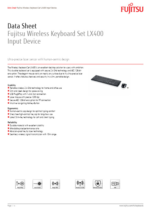
Data SheetFujitsu Wireless Keyboard Set LX400 Input DeviceUltra-precise laser sensor with human-centric designThe Wireless Keyboard Set LX400 is an excellent desktop solution for users with ambition.This durable keyboard set is equipped with secure 2.4 GHz technology and AES 128-bitencryption. The elegant mouse works on nearly any surface due to its ultra-precise lasersensor. It offers fabulous features and security in a slim, portable design.UsabilityReliable wireless 2.4 GHz technology for home and office useSlim and sleek design for space savingUSB Plug&Play with 1-click fast connectionLaser mouse with precise 1200 dpiSecure AES 128-bit encryption for RF connectionIntuitive navigating Hotkey-ButtonErgonomicsHuman-centric cap design for optimal typing comfortStress free high-contrast key cap for long-hour useLatest Slim-Key technology for soft and silent typingReliabilityDurable material with excellent stabilityAffordable price/performance ratioAbrasion-proof key by laser technologySeamless wireless signal transmission with 10m rangeWireless Keyboard Set LX400 Technical specificationsTechnical specification 2.4 GHz, 78 channels, 16 bit, 65.000 IDs Technology 2.4 GHz, 78 channels, 16 bit, 65.000 IDs Special features128 AES encryptionLaser Mouse 1200 DPIKeyboard set with space saving design KeyboardHeight Adjustment 1.5° and 6°Keyboard Type105-key keyboardKeyboard dimension (W x D x H)460 x 156 x 20 mmKeys additional Hotkeys on the F1- F12 keys Keyboard battery info 1 x AAA battery compartment Keyboard radio range max. 10 mPower supply keyboard 1 AAA batteries, max. 1.5VPower consumption keyboard max. 3 mAMouseMouse type RF laser mouseMouse dimension (W x D x H)109 x 62 x 38 mmMouse resolution1200 dpiMouse buttons 2 buttons, 1 wheel as third button Mouse battery info 2 x AAA batteryMouse radio range max. 10 mChannels78ID Codes65000Speed max. 1 Mbps (GFSK) / 256 kbps (DSSS) Power supply mouse 2 AAA batteries, max. 3.3VPower consumption mouse max. 15 mAReceiverReceiver type USB Micro receiverReceiver tech info Conform to USB 1.1 and 2.0Power consumption receiver max. 50 mACharger typePower consumption chargerDimensions / Weight / EnvironmentalDimensions (W x D x H)542 x 169 x 51 mmHeight Adjustment 1.5° and 6°Weight950 gOperating ambient temperature0 - 40°CComplianceEurope CECompliance link https:///sites/certificates/ System requirementsRequired interface USBSoftware support (Operating system)Windows® XPWindows Vista®Windows® 7Package contentPackage content Wireless keyboardWireless mouseUSB Micro receiver1 x AAA battery for keyboard and2 x AAA batteries for mouseQuickstart guideSafety and recycling instructionsManual, warranty,hotline information and comfort software on CD Order codeS26381-K552-L4** (** country code)WarrantyStandard Warranty 2 yearsService level Bring-In / Send-In Service (depending on country)Service Weblink /fts/services/supportContactFUJITSU Technology Solutions Website: /fts2012-10-17 CE-ENworldwide project for reducing burdens on the environment.Using our global know-how, we aim to contribute to the creation of a sustainable environment for future generations through IT.Please find further information at http://www./global/about/environment/delivery subject to availability. Any liability that the data and illustrations are complete, actual or correct is excluded. Designations may be trademarks and/or copyrights of the respective manufacturer, the use of which by third parties for their own purposes may infringe the rights of such owner.More informationAll rights reserved, including intellectual property rights. Changes to technical data reserved. Delivery subject to availability. Any liability that the data and illustrations are complete, actual or correct is excluded.Designations may be trademarks and/or copyrights of the respective manufacturer, the use of which by third parties for their own purposes may infringe the rights of such owner.For further information see /terms Copyright © Fujitsu Technology Solutions。
海斯特(Hyster)4轮驱动型电筒搬运机产品技术指南说明书

J40XNLPRODUCT BROCHURECircled dimensions correspond to the line numbers on the tabulated chart inside the technical guide. Dimensions are in inches (millimeters).2Circled dimensions correspond to the line numbers on the tabulated chart inside the technical guide.Dimensions are in inches (millimeters).3The table below is a helpful guide to visualize the truck run time with different batteries in different applications. (Chart is a guide only and not a replacement for a site survey and full power study.)Heavy – High throughput, typically runs full capacity, runs either attachments or has high liftsMedium – High throughput, runs near capacity without attachments or high liftsLight – lower throughput, runs less than rated capacity without attachments or high liftsNote: Run time is from 100% to Lift-Lock Out. Charge time is from Lift-Lock Out to 100%.45CERTIFICATION: Hyster lift trucks meet the design and construction requirements of B56.1-1969, per OSHA Section 1910.178(a)(2), and also comply with the B56.1 revision in effectat time of manufacture. Certification of compliance with the applicable ANSI standards appears on the lift truck. Performance specifications are for a truck equipped as described under Standard Equipment on this Technical Guide. Performance specifications are affected by the condition of the vehicle and how it is equipped, as well as by the nature, condition of the operating area, proper service and maintenance of the vehicle. If these specifications are critical, the proposed application should be discussed with your dealer.NL = no load, RL = rated load。
AFL OFI-400系列光纤识别标识工具说明书

F i b e r I d e n t i fi c a t i o nOFI-400 Series Optical Fiber IdentifiersAFL’s OFI-400 Optical Fiber Identifiers are rugged, hand-held, and easy-to-use fiber optic test instruments designed to detect and measure the core power levels of optical signals on single-mode optical fiber without disrupting traffic on that fiber. They are simply clamped onto a fiber and display the presence and direction of traffic, continuous test signals, and modulated test tones. This permits network personnel to easily and quickly identify a specific fiber without the risk of disrupting service. All of AFL’s optical light sources are Ideal companions to the OFI-400 family of optical fiber identifiers.No adapters to purchase, store, swap, or misplace: Each OFI-400 uses a unique optical head design featuring a two-position plunger that enables it to be used with 250 µm, 900 µm, and ribbon fiber or 2 mm and 3 mm jacketed fiber. Other brands of optical fiber identifiers require users to purchase, store and change optical plungers each time a different type of fiber is tested.Low insertion loss for in-service ID tasks: OFI-400’s optical heads induces a safe, repeatable macro-bend to the fiber that allows a small amount of light to escape for analysis. The insertion loss induced by the macro-bend is too small to affect the signal on the fiber and the integrity of the fiber is unaffected by the measurement process.Designed for the real world: The OFI-400 family are simple, easy-to-use tools that feature rugged, drop-proof construction - perfect for inside or outside plant use. Their ergonomically designed macro-bend trigger is comfortable to use and the integrated, backlit LCD display enables them to be used in dimly lit spaces. Each OFI-400 uses readily available 1.5 V AAA batteries which can power thousands of fiber tests before needing to be replaced.OFI-400 model: The OFI-400 is designed for use with a wide range of single-mode fibers including 250 μm (bare) coated, 900 µm buffered and ribbon fibers or 2 mm and 3 mm jacketed fibers. The OFI-400 is ideal for network personnel involved in installation, reconfiguration, restoration and maintenance tasks that involve bare, buffered, jacketed or ribbon fibers in outside plant pedestals, fiber cabinets, aerial enclosures and inside plant premises demarcation cabinets. The slim design of the OFI-400 head facilitates access in crowded splice trays.OFI-400C model: Designed specifically for use with 2 mm or 3 mm jacketed single-mode fibers, the OFI-400C is ideal for general purpose maintenance, configuration and installation tasks. The OFI-400C is functionally equivalent to the OFI-400 but includes an optical head design and a calibration scheme optimized for use with jacketed fiber.OFI-400HP model: The OFI-400HP is designed for use where high levels of optical power are present. This includes fibers carrying a single high-power signal, CWDM or DWDM signals with high total power levels, amplified optical signals, or pump lasers associated with EDFA or Raman amplifiers. When display reaches +23 dBm (200 mW) or greater, the OFI-400HP will display “High” warning indication.OFI-400OFI-400C OFI-400HPFeatures•5-year product warranty; 3-year recommended calibration interval •Rugged, hand-held, lightweight, and easy-to-use•Unique optical head with two-position plunger for use with all fiber types•Built-in power meter with Set Reference feature Applications•Live fiber detection to avoid technician-induced outages •Fiber identification and tracing with CW or tones •Core power measurements•Testing 250 µm, 900 µm, and ribbon fiber or 2 mm and 3 mm jacketed fiberOFI-400 Series Optical Fiber IdentifiersNotes:a. All specifications stated above are as measured at 25°C.b. 250 µm coated fiber parameters are specified with OFI plunger in the “250 / 900 / RIB” position. 2 mm / 3 mm jacketed fiber parameters are specified with OFI plunger in the “2 mm / 3 mm” position.c. CW is a light signal that is not modulated. Traffic is a light signal modulated by high speed user data. Tone is a light signal modulated into a nominal 50 % duty cycle square wave.d. Unless noted otherwise, all specifications are typical. Actual results can vary by several dB depending on fiber type, coating material, jacket color, jacket hardness, and other factors.e. SMF-28/28E.SpecificationsaF i b OFI-400 Series Optical Fiber IdentifiersOrdering InformationAll OFI-400 products include a user’s guide, 2 AAA batteries and a soft carry case. Each carries a 1-year warranty and a 3-year recommendedcalibration interval.QualificationsContact ******************* to schedule a demonstration or learn how to buy.Visit /Test to learn more about Optical Fiber Identifiers.International Sales and Service Contact Information available at /Test/ContactsRecommended ProductsFlexScan ® FS300 (quad) and FS200 (single-mode) OTDRs • SmartAuto ® 1-button automated testing for fast results • LinkMap ® color-coded icons for easy troubleshooting• FleXpress ® mode (FS200) completes OTDR test in <5 seconds!• Integrated Source, Power Meter and VFLOptical Light Sources• Encircled Flux Compliant • 5-Year Product Warranty• Integrated LED and Laser light sourcesFS200FS300OLS4OLS2-Dual。
5220FL Fire Alarm系列产品说明书

75 lbs (34 kg) 23 lbs/1000ft (34 kg/km)
Standards and Compliance
Environmental Suitability: Flammability / Reaction to Fire: CPR Compliance: NEC / UL Compliance: European Directive Compliance: APAC Compliance: Plenum Number:
Technical Specifications
Product Overview
Suitable Applications:
Fire Alarm, Monitor/Detection, Circuits: Audio, Control, Initiating, Notification, Noisy Environment
Belden provides the information and specifications herein on an "ASIS" basis, with no representations or warranties, whether express, statutory or implied. In no event will Belden be liable for any damages (including consequential, indirect, incidental, special, punitive, or exemplary damages) whatsoever, even if Belden has been advised of the possibility of such damages, whether in an action under contract, negligence or any other theory, arising out of or in connection with the use, or inability to use, the information or specifications described herein.
Nailor Industries MLS-400组合火 烟扇潜入式控制系统安装说明说明书

L1
L2
120 VAC. (24 VAC)
ADDITIONAL ACTUATOR(S) IF REQUIRED
REOPEN
BRN
M
CLOSED
NORMAL
3 POSITION MASTER CONTROL SWITCH (MCS)
BLK
BLK (RED)
M
WHT (BLK)
SMOKE DETECTOR (IF USED)
3. It is essential that the remote controls include a 3-position master control switch (single pole double throw, center off) and that it is connected to operate as shown.
4. Replace junction box cover and check operation.
OPERATION:
Circuit Test
Combination fire/smoke dampers with the MLS-400 Reopenable Fire Sensor option are supplied with factory mounted spring return actuators that have a power open/fail closed (normally closed) damper connection.
2. MCS Closed Position
The damper will close regardless of whether the primary heat sensor or smoke detector has activated or not.
柏林-福克斯 KFD2-GU-Ex1 温度阈值放大器说明书
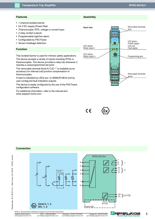
R e l e a s e d a t e 2017-08-09 14:15D a t e o f i s s u e 2017-08-09126797_e n g .x m l789101112I II43521624 V DC14+15-ConnectionAssembly•1-channel isolated barrier •24 V DC supply (Power Rail)•Thermocouple, RTD, voltage or current input •2 relay contact outputs•Programmable high/low alarm •Configurable by PACTware •Sensor breakage detectionFunctionThis isolated barrier is used for intrinsic safety applications.The device accepts a variety of inputs including RTDs or thermocouples. The device provides a relay trip whenever it reaches a userprogrammed set point.The removable terminal block K-CJC-** is available as an accessory for internal cold junction compensation of thermocouples.A fault is indicated by LEDs acc. to NAMUR NE44 and by user-configured fault indication outputs.The device is easily configured by the use of the PACTware configuration software.For additional information, refer to the manual and .FeaturesR e l e a s e d a t e 2017-08-09 14:15D a t e o f i s s u e 2017-08-09126797_e n g .x mlGeneral specifications Signal type Analog inputSupply Connection Power Rail or terminals 14+, 15-Rated voltage U r19 ... 35 V DCRipplewithin the supply tolerance Power dissipation 0.8 W Power consumption 0.8 W InterfaceProgramming interface programming socketInputConnection side field sideConnection terminals 1, 2, 3, 4, 5, 6RTD or resistancetype Pt100 (EN 60751: 1995)type Ni100 (DIN 43760)0 ... 500 Ω (including lead resistance)Measuring current approx. 400 µA with RTD Lead resistance ≤ 50 Ω per lineThermocouples type B, E, J, K, N, R, S, T (IEC 584-1:1995)type L (DIN 43710:1985)Voltage 0 ... 10 V , 2 ... 10 V Current 0 ... 20 mA , 4 ... 20 mA Load 20 Ω for 20 mA; 200 k Ω for 10 VOutputConnection side control sideConnection output I: terminals 7, 8, 9; output II: terminals 10, 11, 12Output I, II relayContact loading 253 V AC/2 A/500 VA/cos φ min. 0.7; 40 V DC/2 A resistive load Mechanical life 2 x 10⁷ switching cyclesTransfer characteristics Resolution temperature: 0.0625 °C, resistance: 62.5 m Ω, voltage: 62.5 µV, current: 625 nA DeviationVoltage input ± 0.02 % of 10 V measuring rangeResistance input ± 0.025 % of measuring range (4-wire connection)Current input ± 0.02 % of 20 mA measuring rangePt100 ± 0.01 % of abs. temperature value of switching point in K + 0.2 K (4-wire connection)Thermocouple± 0.05 % of abs. temperature value of switching point in K + 1.1 K (1.2 K for thermocouple types R and S)this includes ± 0.8 K error of the cold junction compensation (+0.9 K for thermocouple types R and S). Note!Because the sensitivity of thermocouples is, in general, lower at low temperatures than at high temperatures, the specified accuracy figures cannot be guaranteed when measuring temperatures below those listed here.-50 °C (type E and K thermocouples)-100 °C (type J, L and T thermocouples)+500 °C (type B thermocouple)Influence of ambient temperaturePt100 ± (0.0015 % of abs. temperature value of switching point in K + 0.01 K)/K ∆T amb *)Thermocouple± (0.004 % of abs. temperature value of switching point in K + 0.01 K) / K ∆T amb *)Voltage input ± (0.007 % of the switching point voltage) / K ∆T amb *)Current input± (0.004 % of the switching point current)/K ∆T amb *)*) ∆Tamb = ambient temperature change referenced to 23 °C (296 K)Influence of supply voltage < 0.001 % of sensor input rangeInput delay ≤ 370 ms (rise time and energizing delay of relay)Galvanic isolation Output/power supply reinforced insulation according to IEC/EN 61010-1, rated insulation voltage 300 V eff Output I/IIreinforced insulation according to IEC/EN 61010-1, rated insulation voltage 300 V eff Power supply/programming input no electrical isolation Indicators/settings Display elements LEDsConfiguration via PACTwareLabelingspace for labeling at the front Directive conformity Electromagnetic compatibilityDirective 2014/30/EU EN 61326-1:2013 (industrial locations)Low voltageDirective 2014/35/EUEN 61010-1:2010R e l e a s e d a t e 2017-08-09 14:15D a t e o f i s s u e 2017-08-09126797_e n g .x mlConformityElectromagnetic compatibility NE 21:2006Degree of protection IEC 60529:2001Ambient conditions Ambient temperature -20 ... 60 °C (-4 ... 140 °F)Mechanical specifications Degree of protection IP20Connection screw terminalsMass approx. 150 gDimensions 20 x 119 x 115 mm (0.8 x 4.7 x 4.5 inch) , housing type B2Mountingon 35 mm DIN mounting rail acc. to EN 60715:2001Data for application in connection with hazardous areasEU-Type Examination Certificate BAS 98 ATEX 7152Marking ¬ II (1)GD, I (M1) [Ex ia Ga] IIC, [Ex ia Da] IIIC, [Ex ia Ma] I (-20 °C ≤ T amb ≤ 60 °C) , [circuit(s) in zone 0/1/2]InputEx ia Ga, Ex ia Da, Ex ia Ma Voltage U o 10.5 V Current I o 27 mA Power P o 70 mW SupplyMaximum safe voltage U m40 V DC (Attention! The rated voltage can be lower.)Certificate TÜV 99 ATEX 1493 X Marking ¬ II 3G Ex nA nC IIC T4Galvanic isolationInput/Other circuits safe electrical isolation acc. to IEC/EN 60079-11, voltage peak value 375 V Directive conformityDirective 2014/34/EU EN 60079-0:2012+A11:2013 , EN 60079-11:2012 , EN 60079-15:2010International approvals UL approvalControl drawing 116-0173 (cULus)IECEx approval IECEx BAS 06.0022Approved for [Ex ia Ga] IIC, [Ex ia Da] IIIC, [Ex ia Ma] IGeneral information Supplementary informationObserve the certificates, declarations of conformity, instruction manuals, and manuals where applicable. For information see .Power feed module KFD2-EB2The power feed module is used to supply the devices with 24V DC via the Power Rail. The fuse-protected power feed module can supply up to 150individual devices depending on the power consumption of the devices. A galvanically isolated mechanical contact uses the Power Rail to transmit collective error messages.Power Rail UPR-03The Power Rail UPR-03 is a complete unit consisting of the electrical inset and an aluminium profile rail 35mm x 15mm. To make electrical contact, the devices are simply engaged.Profile Rail K-DUCT with Power RailThe profile rail K-DUCT is an aluminum profile rail with Power Rail insert and two integral cable ducts for system and field cables. Due to this assembly no additional cable guides are necessary.Power Rail and Profile Rail must not be fed via the device terminals of the individual devices!K-CJC-**This removable terminal block with integrated temperature measurement sensor is needed for internal cold junction compensation for thermocouples. One K-CJC-** is needed for each channel.PACT ware ™Device-specific drivers (DTM)Adapter K-ADP-USBProgramming adapter for parameterisation via the serial USB interface of a PC/NotebookAccessories。
E4980A 精密 LCR 表用户指南
E4980A中的LED是一级产品,符合IEC60825-1的一级LED产品标准。 • 将仪器接地
为了避免电击,必须用所附三相电源线的接地插脚将仪器底盘和机壳接地。 • 切勿在易爆环境中操作
切勿在有易燃气体或烟雾的环境中操作仪器。显然,在这种环境下操作任何 电子仪器都存在安全隐患。 • 远离带电电路
表示示例1、示例2和示例3(菜单、按钮或方框)的 顺序操作。“-”可省略。
6
文档地图
以下手册适用于Keysight E4980A。 • 用户指南(制造号E4980-900x0,附属于选件ABA,英文版) 本手册描述了有关E4980A的大部分基本信息。它提供了每个功能的详细操作步骤(从 功能概览到系统设置)、测量示例、选件、附件、技术指标、GPIB命令、功能键功能列 表及错误消息。
Keysight E4980A 精密 LCR 表
用户指南
注意事项
切勿超出适合所用仪器的工作输入功率、电压和电流电平及信号类型,请参见仪器的功 能调用。
静电放电(ESD)可能对用户仪器的高灵敏微型电路造成损害。这种静电放电极易在连 接或断开测试夹具时产生。可以通过在夹具上安装一条能够提供高电阻通路的接地母线,从 而使这些电路避免受ESD的损害。另外,在触摸测试端口连接器之前,用户也可先接触任何 接地仪器底盘的外壳使自身接地,以释放任何已建立的静电。
如果是德科技指定仪器使用的软件和固化软件正确安装在此仪器上,则是德科技 保 证其软件和固化软件能执行其编程指令。是德科技不保证仪器、软件或固化软件的操 作不 间断或无差错。
保修限制
上述保修不适用于因以下情况导致的缺陷:买方维护不当或不充分;买方提供软件或 接口;未经授权的改装或误用;在产品环境规范之外的环境中操作;或者工作场地准备或 维护不当。
MadgeTech HiTemp140-PT 高温数据日志器指南说明书
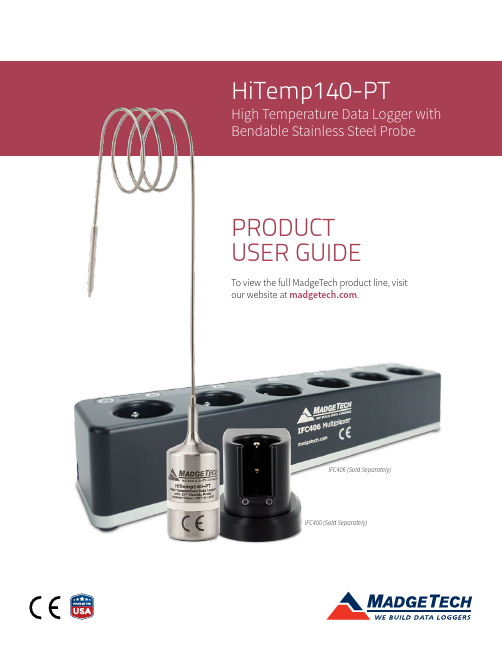
High Temperature Data Logger with Bendable Stainless Steel ProbeIFC406 (Sold Separately)IFC400 (Sold Separately)PRODUCT USER GUIDETo view the full MadgeTech product line, visit our website at .Product OverviewThe HiTemp140-PT is a submersible, temperature data logger that can operate from -20 °C (-4 °F) up to 140 °C (284 °F) and has an accuracy of +/-0.1 °C (0.18 °F). The device features a 12 or 24 inch bendable stainless steel probe for measuring extended temperatures up to 350 °C (662 °F). The probe is durable and can be spiraled, bent or angled in any direction, making it easy to log temperatures within bottles, vials or other hard to reach places. Water ResistanceThe HiTemp140-PT is fully submersible and is rated IP68. It can be placed in environments with up to 230 feet (70 m) of water.Bend RadiusThe flexible probe on the HiTemp140-PT can be bent to a .25 inch bend radius. The probe should not be bent within 1 inch of either weld joint.Installation GuideInstalling the SoftwareThe Software can be downloaded from the MadgeTech website at . Follow the instructions provided in the Installation Wizard.Installing the Docking StationIFC400 or IFC406 (sold separately)— Connect the device into a USB port with the interface cable and install the drivers.Ordering Information• 900230-00 — HiTemp140-PT-1 (1 inch piercing tip)• 902152-00 — HiTemp140-PT-1-KR (key ring end cap)• 900243-00 — HiTemp140-PT-5 (5 inch piercing tip)• 900306-00 — HiTemp140-PT-12 (12 inch piercing with1 inch probe tip)• 900319-00 — IFC400• 900325-00 — IFC406• 900097-00 — ER14250MR-145Device OperationConnecting and Starting the Data Logger1. Once the software is installed and running, plug theinterface cable into the docking station.2. Connect the USB end of the interface cable into anopen USB port on the computer.3. Place the data logger into the docking station.4. The data logger will automatically appear underConnected Devices within the software.5. For most applications, select Custom Start fromthe menu bar and choose the desired start method, reading rate and other parameters appropriate for the data logging application and click Start. (Quick Start applies the most recent custom start options, BatchStart is used for managing multiple loggers at once,Real Time Start stores the dataset as it records while connected to the logger.)6. The status of the device will change to Running,Waiting to Start or Waiting to Manual Start,depending upon your start method.7. Disconnect the data logger from the interface cableand place it in the environment to measure.Note: The device will stop recording data when the end of memoryis reached or the device is stopped. At this point the device cannot be restarted until it has been re-armed by the computer.Downloading Data from a Data Logger1. Place the logger into the docking station.2. Highlight the data logger in the Connected Device slist. Click Stop on the menu bar.3. Once the data logger is stopped, with the loggerhighlighted, click Download. You will be prompted to name your report.4. Downloading will offload and save all the recordeddata to the PC.Device Operation (cont’d)Trigger SettingsThe device can be programmed to only record based off user configured trigger settings.1. In the Connected devices panel, select the intendeddevice to change the settings.2. On the Device tab, in the Information group, clickProperties. Users can also right-click on the deviceand select Properties in the context menu.3. Click Trigger and configure the Trigger settings.Trigger formats are available in Window and Two Point (bi-level) mode. Window mode allows for one range of temperature monitoring and two point mode allows for two ranges.Set PasswordTo password protect the device so that others cannot start, stop or reset the device:1. In the Connected Devices panel, click the device desired.2. On the Device Tab, in the Information Group, clickProperties. Or, right-click the device and selectProperties in the context menu.3. On the General Tab, click Set Password.4. Enter and confirm the password in the box thatappears, then select OK.Device MaintenanceO-RingsO-ring maintenance is a key factor when properly caring for the HiTemp140-PT. The O-rings ensure a tight seal and prevent liquid from entering the inside of the device. Please refer to the application note O-Rings 101: Protecting Your Data, found at , for information on how to prevent O-ring failure.Battery ReplacementMaterials: ER14250MR-145 Battery1. Unscrew the bottom of the logger and remove thebattery.2. Place the new battery into the logger. Note the polarityof the battery. It is important to insert the battery with positive polarity pointing upward towards the probe.Failure to do so could result in product inoperability or potential explosion if exposed tohigh temperatures.3. Screw the cover back onto the logger. RecalibrationMadgeTech recommends annual recalibration. To send devices back for calibration, visit .Note: This product is rated for use up to 140 °C (284 °F). Please heed the battery warning. The product will explode if exposed to temperatures above 140 °C (284 °F).6 Warner Road, Warner, NH 03278(603) 456-2011******************Product Support & Troubleshooting• Visit our Resources online at /resources .• Contact our friendly Customer Support Team at (603) 456-2011 or *********************.MadgeTech 4 Software Support• Refer to the built-in help section of the MadgeTech 4 Software.• Download the MadgeTech 4 Software Manual at .• Contact our friendly Customer Support Team at (603) 456-2011 or *********************.Disclaimer & Terms of UsePublished specifications can be used to determine maximum allowable exposure times for the HiTemp140 with Thermal Shield at different temperatures beyond the normal operating range of the logger. Both the data logger and Thermal Shield must be at ambient temperature (approximately 25 °C) before being placed in the extreme temperature environment. Immediately following exposure to high temperature, the data logger should be removed from the thermal shield(using appropriate precautions, as it could be VERY hot) OR the data logger and shield should be placed in a water bath (approximately 25 °C) for at least 15 minutes to allow it to cool. Failing to do this may allow heat trapped in the Thermal Shield to continue to heat the data logger to potentially unsafe levels.If your application involves a ramp up to a temperature above 140 °C and/or any complex temperature profile that isn’t simply a constant temperature, please contact MadgeTech to determine whether the HiTemp140 with Thermal Shield is suitable. Please provide MadgeTech with a detailed description of your temperature profile, including temperatures, durations, ramp times, and process media (air, steam, oil, water, etc.) If MadgeTech is unable to definitively calculate the suitability of our product for your application, we can provide a test unit outfitted with a high temperature indicator sticker. This sticker has an indicator dot which will turn black if exposed to temperatures above 143 °C. Apply the sticker to the bottom of the data logger itself (not the thermal shield), remove the battery for safety, place the data logger into the thermal shield and run the assembly through the proposed temperature program. The first indicator dot on the sticker will turn black at 143 °C. If that happens, the HiTemp140 with thermal shield is not appropriate for the application and we will work to find a solution that is.。
GEM20U系列曲折缝纫机使用说明书

GEM20U SERIESZIGZAG SEWING MACHINE 系列曲折缝缝纫机非常感谢您购买本公司的工业缝纫机。
在使用缝纫机之前,请仔细阅读<为了您的安全使用>和使用说明书。
工业缝纫机的特性之一,是要在机针和旋梭等运动零部件附近进行操作,而这些零部件很容易引起受伤的危险,所以请在接受过培训的人员或有熟练操作技术的人员的指导下,正确地使用本缝纫机。
为了您的安全使用1.安全使用的标记及其意义本使用说明书及产品所使用的标记和图案记号是为了您的安全而正确地使用本产品,防止您及他人受到危害和损害。
表示方法及含义如下:说明图案和符号圆圈中的图案表示必须要做的内容。
(如左图的符号表示“必须接地”。
)危险注意如果忽视此标记而进行了错误的操作,必将导致人员死亡或重伤。
如果忽视此标记而进行了错误的操作,有可能会引起人员受伤及造成设备损坏。
符号△表示“应注意事项”。
三角中的图案表示必须要注意的内容。
(如左图的符号表示“注意受伤”。
)符号○表示“禁止”。
符号●表示“必须”。
Thank you very much for buying our sewing machine.Before using your new machine,please read the safety instructions below and the explanations given in the Operation Instruction.With industrial sewing machines,it is normal to carry out work while positioned directly in front of moving parts such as the needle and thread take-up lever,and consequently there is always a danger of injury that can be caused by these parts.Follow the instructions from training personnel and instructors regarding safe and correct operation before operating the machine so that you will know how to use it correctly.SAFETY INSTRUCTIONS1.Safety indications and their meaningsThis instruction manual and the indications and symbols that are used on the machine itself are provided in order to ensure safe operation of this machine and to prevent accidents and injury to yourself or other people.The meaning of these indications and symbols are given below.IndicationsDANGER CAUTIONThe instructions which follow this term indicate situations where failure to follow the instructions will almost certainly result in death or severe injury.The instructions which follow this term indicate situations where failure to follow theinstructions could cause injury when using the machine or physical damage to equipment and surroundings.SymbolsT his symbol (△) indicates something that you should be careful of. The picture inside the triangle indicates the nature of the caution that must be taken.(For example, the symbol at left means"beware of injury".)This symbol (○) indicates something that you must not do.This symbol (●) indicates something that you must do. The picture inside the circle indicates the nature of the thing that must be done.(Forexample,thesymbol atleft means "you must make the groundconnection".)安全注意事项打开控制箱盖时,必须先关闭电源开关并将电源插头从插座上拔下,至少等待5分钟后,再打开控使用环境Notes On Safety安全注意事项Notes On Safety1245556677888999101011111113-441.技术规格及用途 Main Technical Specifications And Application ......................................................2.机器安装 Installation ......................................................................................................................3.操作准备 Installation ......................................................................................................................4.缝线的选择 Selection of stitches ....................................................................................................5.机针缝线和缝料的配合 Coordination of needle Thread and material ................................................6.机针安装 Assemblage of needle ....................................................................................................7.绕梭心线 Winding thread around the shuttle core .........................................................................8.穿面线和引底线 Threading surface and Bottom stitches .................................................................9.装梭心 Mounting of shuttle core ....................................................................................................10.装卸梭心套 Mounting and Dismounting of the case (of the shuttle core)......................................11.针距的调节 Adjustment of needle distance ..................................................................................12.压脚压力的调节 Adjustment of the pressure of presser foot .........................................................13.绣花机绣花前准备工作 Preparations before embroidery ................................................................14.缝线的张力 Tension Of Stitches ...................................................................................................15.底线张力的调节 Adjustment of Bottom sitich Tension ...................................................................16.面线张力的调节 Adjustment of the surface stitch Tension .............................................................17.横针针迹对称位置调节 Regulation of symmetrical position of horizontal stitches .........................18.旋梭定位 Location of rotating shuttle .........................................................................................19.针杆高度 Height of the needle staff ............................................................................................20.旋梭的装卸 Mounting and Dismounting of Rotating shuttle ........................................................21.一般故障及其处理方法 Faults Locating And How To Treat ............................................................零件样本 .....................................................................................................................................1.技术规格及用途 Main Technical Specifications And Application名 称Description 曲折缝Curved-stitching双针曲折缝Double Curved-stitching最大线迹长度Max. length of stitches5毫米5mm直齿 12毫米(23/43/63)Straight tooth 12mm(23/43/63)5毫米5mm斜齿 8毫米(33/53/93/123T/457C)Straight tooth 8mm(33/53/93/123T/457C)帽眼 6毫米(53B)Cap apertare 6mm(53B)双针间距Distance between double stitches 手提Hand stitch 膝提Kneeing stitch压脚提升高度Height of presser foot最大缝纫厚度机针规格Max. Thickness of sewing Specification of needle6毫米(指单针摆动宽度)6mm (Swaying width of single needle)2.5,3.5,4.5(可换)2.5,3.5,4.5(changeable)不小于6毫米No less than 6mm12毫米12mm不少于8层纱卡No less than 8 layers不少于8层纱卡No less than 8 layers12毫米12mm不小于6毫米No less than 6mm最高缝速Max. Speed 2000针/分2000 stitches/minDP×5 (Nm70-130)缝线ThreadNO.40-100涤棉线或类似丝线NO.40-100 terylene and the likeNO.40-100涤棉线或类似丝线NO.40-100 terylene and the like机头体积(长×宽×高)Dimension of machine head (L W H)××540250370毫米××540×250×370mm19/25.5≥250W净重/毛重N.W/G.W 电动机功率Motor power用途Application粗缝、拼缝、套结缝及一般Z 字形缝For rough stitching loop stitching and z-shape stitching双针条状及曲折装饰缝For double stitching and curved-stitching decorations最大提升宽度Max. Swaying width2.机器安装 Installation(1)油盘安装:用四只圆钉②将油盘①固定在台板框孔内,并确保油盘至台板面距离为25毫米,油盘右边缘与台板右框边平齐。
Ficoll 400产品说明书

Product Information SheetFicoll ® 400Catalog Number F4375Product DescriptionFicoll 400 is a highly branched polymer formed by the copolymerization of sucrose and epichlorohydrin. Ficoll 400 is completely non-ionic. Because of the abundance of hydroxyl groups, Ficoll 400 is veryhydrophilic and extremely water-soluble. The most common application for Ficoll 400 is as a density gradient medium for the separation and isolation of eukaryotic cells, organelles, and bacterial cells. Density ranges up to 1.2 g/ml can be attained. It has also been utilized in a variety of other applications.Precautions and DisclaimerFor R&D use only. Not for drug, household, or other uses. Please consult the Safety Data Sheet for information regarding hazards and safe handling practices.Physical PropertiesAppearance: White to off-white powder Loss on drying: Not more than 5%1 Molecular Weight: 400,000 +/- 100,000 asdetermined by intrinsic viscosity 1 Specific Rotation: +56.5 at 20 C (C=1% inwater)1 Intrinsic viscosity: approximately 0.17 dl/g 1 Dialyzable material including NaCl: less than1%1 Stokes Radius: approximately 10 nm 1Unlike sucrose, solutions of Ficoll haverelatively low osmolality. Despite this, the density of Ficoll in aqueous solutions is comparable to that of sucrose.Because of the high molecular weight and low content of dialyzable material, Ficoll has a much lower permeability towards cell membranes than sucrose. Therefore, cells can be expected to collect at a lower density in Ficoll gradients than in sucrose gradients. Because of its low membrane permeability and low osmotic pressure, separations in Ficoll normally result in better preservation of cell function and morphology.Storage/StabilityStored at room temperature, Ficoll 400 can be expected to have a shelf-life of 5 years. Concentrations of 50% (w/v) can be attained in water. Ficoll should be added slowly with constant stirring.Sigma tests the solubility of Ficoll 400 at 1 g in 10 ml of deionized water yielding a clear to slightly hazy, colorless to faint yellow solution. Ficoll is stable in alkaline andneutral solutions. At pH values below 3, it is rapidly hydrolyzed, particularly at elevated temperatures. Ficoll can be sterilized by autoclaving at a neutral pH, at 110 C for 30 minutes. Strong oxidizing and reducing agents are to be avoided.ProcedureCentrifugationFicoll 400 can be used for gradientcentrifugation in all types of centrifuge rotors and for separation at unit gravity. For centrifugation, both discontinuous and continuous gradients are possible.Discontinuous gradients offer two main advantages: First, the abrupt changes in Ficoll 400 density mean that isolated cells are found in sharp bands at the interface between layers of different densities. This allows for easy removal of the sample with a pipette. Second, cells with great differences in density can be easily isolated with as few as two density layers. This is achieved by choosing densities which will prevent one or more cell types from entering the lower phase, banding these cell types at theinterface. To estimate the densities required for a particular application, consult Table 1. The graph of densities of Ficoll as a function of concentration is also provided.Table 1Preparing a discontinuous gradient1. Prepare Ficoll 400 in buffer or isotonicsucrose solution (0.25 M) atconcentrations which should separate the material of interest. Most cells and organelles have a buoyant densitybetween 1.0 and 1.2 g/ml in Ficoll 400. Often a two-layer gradient is sufficient. Solutions made at this step may be stored in the refrigerator but should be used at room temperature.2. In standard centrifuge tubes, makelayers (approximately 1 cm deep) with the densest layer on bottom.3. Taking care not to mix the layers of thegradient, carefully layer the sample on top. Stir the sample and the uppermost Ficoll 400 layer gently with a glass rod to eliminate the interface before centrifugation.During centrifugation the various particles will collect either in or between the Ficoll layers, depending on their density. Upon completion of centrifugation, pipette off the various phases and remove the Ficoll from the fractions of interest. Ficoll may beremoved from isolated cells and organelles by repeated cycles of dilution with bufferfollowed by centrifugation. Residual amounts of Ficoll 400 in the sample can be estimated with the anthrone reaction.2In some instances, a continuous or linear density gradient may be desired. This can be easily prepared using a gradient mixer. For simple separations, a homologous Ficoll 400 solution without a gradient can be used. Fractionation is accomplished by stepwise increases in centrifugation speed. Ficoll has also been employed in zonal centrifugation studies.3Unit gravity sedimentation through a density gradient is widely used to separate cells which are sensitive to centrifugation. Cells with similar densities but different sizes can also be efficiently separated at unit gravity.4,5,6Nucleic Acid HybridizationFicoll 400 is a constituent of Denhardt’ssolution used in Northern and Southern blot analysis. Ficoll reduces non-specific binding of material to nitrocellulose membranes during nucleic acid hybridization.7Sigma offers Denhardt’s Solution, 50× concentrate (Catalog No. D2532) which is tested for use in nucleic acid hybridization. Typical hybridization solutions require a 5× concentration of Denhardt's solution.Immunological ApplicationsFicoll 400 has been employed as a hapten carrier, and has been conjugated todinitrophenol, trinitrophenol, and fluorescein isothiocyanate for the purpose of enhancing primary immune response in mice. Conjugates with a range of substitution levels and minimal toxicity are easily prepared.8,9Chemically Defined Cell Culture MediaFicoll is used with and without serum-derived growth factors to support the growth of both primary cultures and established cell lines.10,11Concentration DialysisFicoll 400 is useful for concentratingsolutions by dialysis since its high molecular weight prevents it from crossing the dialysis membrane. Osmotic pressure draws water across the membrane into the solution of Ficoll 400, effectively concentrating sensitive materials.1ElectrophoresisContinuous flow electrophoresis usually requires a stabilizer in the electrolyte. Ficoll 400 is often used for this application.12,13Phase PartitioningPhase partitioning separates cells on the basis of surface properties. Ficoll 400 is combined with polyethylene glycol in two-phase systems, and with dextran and polyethylene glycol in three phase systems.14,15Physiological Perfusion and Cell Stabilization SolutionsFicoll has been added to physiological saline perfusate during monitoring of protein excretion in vessels.Vitrified mouse embryos have been diluted with solutions containing 30% Ficoll plus 0.5 M sucrose.17 Isolated rat kidneys were perfused with Tyrode’s solution containing 4.7% Ficoll 400.18Cited References1. Supplier Data2. Scott, T.A. and Melvin, E.H., Anal.Chem ., 25, 1656 (1953). 3. Lavrenko, P. N. et al., Anal. Biochem .,166, 287 (1975). 4. Tulp, A. et al . Anal. Biochem ., 67, 11(1975). 5. Bont, W.S. et al ., J. Immunol. Methods ,29, 1 (1979). 6. Niskanen, E. et al ., Cell Tissue Kinet ., 18,399 (1985). 7. Sambrook, J. et al., Molecular Cloning: ALaboratory Manual, Cold Spring Harbor Laboratory (1989), p. 9.48 - 50, B.15. 8. McMasters, P. R. B. et al .,Immunochemistry , 14, 189 (1977). 9. Inman, J.K., J. Immunol ., 114, 704(1975).10. Clark, J., in Hormonally Defined Media,Lecture Posters, Eur. Conf. Serum-Free Cell Culture, Fisher, G. and Wieser, R.J., (eds), Springer (Berlin), 6 (1983). 11. Kao, K. N., Z. Pfanzenphysiol. Bd ., 103,437 (1981). 12. Platsoucas, C. D. and Catsimpoolas, N.,J. Immunol. Methods , 34, 31 (1980). 13. Platsoucas, C. D. et al., Cell. Immunol .,51, 238 (1980). 14. Johansson, G. and Loelsson, M.J., J.Chromat ., 464, 49 (1989). 15. Albertson, P. A. and Birkenmeier, G.,Anal. Biochem ., 175, 154 (1988). 16. Nolly, H. and Nolly, A., Biol. Res ., 31(3),169 (1998). 17. Mukaida, T. et al ., Hum. Reprod ., 13,2874 (1998). 18. Barthelmebs, M ., Arch. Mal. Coeur.Vaiss., 91, 1083 (1998).Other ReferencesCell separationGonadal primordial germ cells Hong Y.H. et al., Transgenic Res ., 7, 247(1998) Red blood cellsAtawodi, S.E. et al ., Cancer Epidemiol. Biomarkers Prev ., 7, 817 (1998) Fetal nucleated red blood cellsOosterwijk, J.C., Prenat. Diagn .,18, 1082 (1998)Peripheral blood cellsKrackhardt, A. et al ., Exp. Hematol ., 26, 1265 (1989)Peripheral blood mononuclear cellsWoods, J. A. et al., J. Gerontol. A. Biol. Sci. Med. Sci., 53, B430 (1998)Schlenke, P., Clin. Diagn. Lab. Immunol ., 5, 808 (1998)Hull. D.R., Ren. Fail ., 20, 607 (1998) LymphocytesKrieger, K. et al ., Pharmacopsychiatry ., 31, 193 (1998)Pancreatic islet cellsBrandhorst, H. et al ., Cell. Transplant ., 7, 489 (1998)Lakey, J.R., Transplant ., 7, 479 (1998) Yeast vacuolesVida, T.A., J. Cell Biol ., 111, 2871 (1990) ProteolysosomesShrishailam, Y. et al ., Proc. Natl. Acad. Sci . USA, 84, 246 (1987) Murine bone marrow cellsSchneider, E. et al., J. Immunol ., 139, 3710 (1987) CytoplastsVolloch, V. et al ., J. Cell Biol ., 105, 137 (1987)Related ProductsFicoll 70, Catalog No. F2878Ficoll solution, Type 400, 20% in H 2O,Catalog No. F5415 Ficoll 400 BioXtra, Type 400-DL, lyophilizedpowder, Catalog No. F1418 Ficoll 400 Type 400-DL, lyophilized powder,Catalog No. F9378 Ficoll 400 lyophilized powder, γ-irradiated,BioXtra, suitable for cell culture, Catalog No. F8636 Ficoll 400 BioXtra, for molecular biology,lyophilized powder, Catalog No. F2637NoticeWe provide information and advice to our customers on application technologies and regulatory matters to the best of our knowledge and ability, but without obligation or liability. Existing laws and regulations are to be observed in all cases by our customers. This also applies in respect to any rights of third parties. Our information and advice do not relieve our customers of their own responsibility for checking the suitability of our products for the envisaged purpose.The information in this document is subject to change without notice and should not be construed as a commitment by the manufacturing or selling entity, or an affiliate. We assume noresponsibility for any errors that may appear in this document.Contact InformationFor the location of the office nearest you, go to /offices.Technical ServiceVisit the tech service page on our web site at /techservice.Standard WarrantyThe applicable warranty for the products listed in this publication may be found at/terms.F4375 Product Information Sheet Rev 03/2021The life science business of Merck operatesas MilliporeSigma in the U.S. and Canada.。
- 1、下载文档前请自行甄别文档内容的完整性,平台不提供额外的编辑、内容补充、找答案等附加服务。
- 2、"仅部分预览"的文档,不可在线预览部分如存在完整性等问题,可反馈申请退款(可完整预览的文档不适用该条件!)。
- 3、如文档侵犯您的权益,请联系客服反馈,我们会尽快为您处理(人工客服工作时间:9:00-18:30)。
Leagene 。
com 北京雷根生物技术有限公司
Ficoll 400裂解液(20% w/v)
简介:
Ficoll 400又称聚蔗糖400,分子量40KD ,具有无毒、低渗透压、密度高等特性,容易使细胞聚集,是分离细胞或细胞器较好的介质。
Ficoll 400裂解液用于分级梯度分离细胞器如完整细胞核等,主要由PM 缓冲液、Ficoll 400、蛋白酶抑制剂等组成,经过滤除菌。
组成:
操作步骤(仅供参考):
1、根据实验要求操作。
注意事项:
1、 注意无菌操作,避免反复冻融。
2、为了您的安全和健康,请穿实验服并戴一次性手套操作。
有效期: 6个月有效。
4℃可储存1个月。
相关:
编号 名称 CS0020 Storage Ficoll 400裂解液(20% w/v) 100ml -20℃ 使用说明书 1份 编号 名称
CC0007 磷酸缓冲盐溶液(10×PBS,无钙镁)
CC0022 D-Hanks 平衡盐溶液(1×,含酚红)
CC0130 胰蛋白酶-EDTA 溶液(0.25%:0.02%)
CS0001 ACK 红细胞裂解液(ACK Lysis Buffer)
DG0005 糖原PAS 染色液
PW0053 Western 抗体洗脱液(碱性)
TC0713 葡萄糖检测试剂盒(GOD-POD 比色法)。