压力表标示贴使用说明
CWY系列精密数字压力表使用说明书
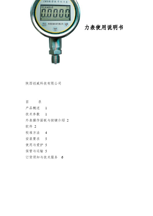
CWY系列精密数字压力表使用说明书CWY系列周密数字压力表使用讲明书陕西创威科技有限公司目录产品概述1技术参数1外表操作面板与按键介绍2软件2校准方法4安装要求5使用与爱护5保管与运输5订货须知与技术服务6一、产品概述CWY周密数字压力表是我公司按照国家最新标准研制生产的高精度智能压力测量外表。
CWY系列数字压力表要紧由压力传感器和信号处理电路组成。
采纳进口的压力传感器,性能优越,具有精度高、抗腐蚀性、抗冲击、抗震动、低温漂、高稳固性等优点;信号处理电路采纳最新的超低功耗处理器、信号处理芯片及电源治理芯片组成。
采纳大容量高性能锂电池供电,无需外部电源供电。
该外表外观精巧、小巧、美观,使用操作简单。
CWY系列周密数字压力表按压力特性可分为:表压、差压和绝压三种。
按压力量程可分为:微压、中低压、高压。
要紧应用于各级计量部门对各种压力(差压)变送器、一般压力表、血压计等其它压力仪器外表进行校验。
二、技术参数1.测量范畴:(-0.1~250)MPa2.输出信号:4~20mA、RS485、0~5V(可选)3.准确度等级:0.05级、0.1级、0.2级、0.4级4.显示方式:5位数字动态显示+模拟光柱指示5.过载压力:1.5~2倍的量程6.关闭电流:<20μA7.供电电源:3.6V高能双节锂电池,寿命2到3年8. 介质温度:(-45~120 )℃9.工作环境:温度:(-20~60)℃;湿度:≤85%RH;校正参比环境:(20±2)℃10.温度补偿范畴:(0~50)℃11.防爆级不:ExiaIICT412. 防护等级:IP6513. 过程接口:M20×1.5(外螺纹),专门的螺纹接口需要定制-1-三、外表操作面板与按键介绍采样状态下的功能:“开关”键:开关机功能键。
当外表不使用时能够关闭,以降低功耗。
用磁笔刷一下此键,2秒内显示该外表量程的起始点和满量程点,外表进入测量状态;再刷一下此键,2秒后外表进入关机状态。
压力表检定标签

压力表检定标签【原创实用版】目录1.压力表检定标签的概述2.压力表检定标签的作用3.压力表检定标签的类型4.压力表检定标签的使用方法5.压力表检定标签的注意事项正文一、压力表检定标签的概述压力表检定标签,是用于标记压力表经过检定、校准或维修的标签,通常由检定机构或专业人员粘贴在压力表上,以证明压力表已经过检定,并具备一定的精度和可靠性。
二、压力表检定标签的作用压力表检定标签主要有以下几个作用:1.证明压力表已经过检定,可以正常使用。
2.标记压力表的检定周期,提醒用户定期进行检定。
3.记录检定结果,供用户或检定机构查阅。
4.便于检定机构对压力表进行后续的管理和监督。
三、压力表检定标签的类型根据检定标签的内容和形式,压力表检定标签可以分为以下几种类型:1.普通标签:只标记压力表的检定日期和下次检定日期。
2.详细标签:除了标记检定日期和下次检定日期外,还标记检定结果、检定单位等详细信息。
3.电子标签:通过电子设备打印的标签,内容可以随时修改,方便检定机构进行管理。
四、压力表检定标签的使用方法1.选择合适的标签:根据压力表的检定需求和检定机构的要求,选择适当的标签。
2.粘贴标签:将标签粘贴在压力表的明显位置,确保易于查看。
3.记录检定结果:在标签上记录检定日期、下次检定日期和检定结果等信息。
4.保护标签:在使用过程中,要注意保护标签,防止标签损坏或信息模糊。
五、压力表检定标签的注意事项1.标签应粘贴在压力表的明显位置,以便于查看。
2.标签上的信息应完整、清晰,不得涂改或损坏。
3.如发现标签上的信息有误或模糊,应及时更换新的标签。
高手讲解压力表使用说明----YS-2.15

YS-1型压力表使用说明书一、概述首先天津市建筑仪器制造厂位于我国建筑仪器发源地--天津市,是较早生产试验仪器的厂家之一,具有近很长的生产试验仪器设备的历史。
主要经营水泥,混凝土,土工,涂料检测等仪器,能供应实验室成套试验仪器设备,并提供安装、调试、维修及技术指导一条龙服务。
本厂多年来以规模大、产品多、型号齐全、信守合同而著称,用户遍及全国各地区、各行业。
并积极与全国大专院校及科研质检单位紧密联系,共同研发,升级改造各种试验仪器,在工程检测界享有较高的声誉。
对于我厂供应的所有仪器设备,均负责相应的现场指导。
我厂拥有一支高素质的技术队伍和精良的加工设备, 先进的制作工艺及完善的检测手段,并不断从事新产品的研制和开发,生产出高品位、高质量的产品以满足市场的需要。
我们以多元素的产品种类,精良的质量,低廉的价格,良好的售后服务,赢得了各界客户的厚爱。
让客户购的放心,用的称心是我们的宗旨,永远第一是我们追求的目标,仪器仪表技术电话:/ 63385288YS-1型数字压力表(简称仪表)是以单片机和16位分辨率的A/D芯片为核心构成有较高精度的新型通用数字压力表。
该仪表显示四位有效数字。
YS-1型压力表具有如下特点:1.自动清零。
仪表通电后自动消除偏差值使输出显示为零值。
2.峰值保持。
在峰值保持状态,仪表始终显示最大压力值。
3.数据存储。
能存储200个压力值,可以随时调出显示和清除。
4.自动关断。
仪表具有延时断电功能,延长电池使用寿命。
5.线性校正。
仪表最多可设置9个校正点,提高了显示的准确度。
6.参数设置。
仪表标定时参数设置由按键完成,通用性强。
二、主要参数压力传感器规格标准配置60MPa,连接螺纹M20×1.5标准配置30MPa,连接螺纹M20×1.5精度等级≤1电源/ V 9(6F22型电池1节)工作电流/mA ≤10 三、按键名称及功能峰值状态调零状态不清零提示有存储数据电池电压低图1面板图除了开关键以外,其他3个按键都有上下档功能。
压力表标示贴使用说明

压力表标示贴使用说明
一、根据设备上压力表的量程和设备正常工作时的
压力范围划分颜色区域。
例如:右图中压力表量程为0-
1.6MPa,该压力表使用在化糖锅上。
化糖锅正常工作时,
压力范围在:0.4-0.8MPa(即4-8公斤压力)。
那么,
0-0.4MPa为黄色区域,表示压力偏低。
0.4-0.8MPa 为绿色区域,表示压力正常。
0.8-1.6MPa为红色区域,表示压力过高。
(此事例仅供参考,以现场实际情况为准)
二、根据上面的颜色区域,将标示贴裁剪
合适长度。
三、将裁减好的标示贴贴到压力表对应的量程上。
注:1、压力表表面直径为10cm。
2、压力表使用在熬糖锅,化糖锅,储气罐等压力容器上。
符合上述两条的压力表可用此标示贴。
压力表使用规范(最新版)
压力表使用规范为加强在用压力表的管理,确保压力表完好,规范压力表的使用,制定如下规定,望认真执行;1.压力表的选用1.1选用的压力表,应当与压力容器、管道内的介质相适应。
1.2设计压力小于1.6MPa压力容器、管道使用的压力表精度(注1)不得低于2.5级;设计压力大于或者等于1.6MPa压力容器、管道使用的压力表精度不得低于 1.6级。
1.3工艺用压力表(注2)表盘刻度极限值应为最大允许工作压力(注3)的 1.5-3.0倍,最好取2倍左右。
在满足工艺要求的条件下优先选用外壳公称直径100mm的压力表(很重要)。
---压力表选型依据1.4压力表在测量稳定负荷时不得超过量程的2/3,测量波动压力时,不应超过量程的1/2,至于最低压力,在以上两种情况下,均不应低于量程的1/3。
---压力表选型依据2.压力表的校验2.1压力表安装前应进行校验,然后每隔半年校验一次。
2.2需要强检的压力表由设备科负责外出校验,校验后的压力表应将检验标志贴在表盘上,并注明下次校验日期或有效期。
2.3非强检的压力表可根据检定的压力表进行自校,并做好自校记录。
3.压力表的安装要求3.1装设位置应便于操作人员观察和清洗,且应避免受到辐射热,冻结或振动的不利影响。
3.2压力表与压力容器、管道之间,应装设三通旋塞或针型阀;三通旋塞或针型阀应有开启标记;压力表与压力容器、管道之间,不得连接其他用途的任何配件或接管。
3.3用于蒸汽介质的压力表,在压力表与压力容器、管道之间应装有存水弯管。
使蒸汽在这一段弯管内冷凝,以避免高温蒸汽直接进入压力表的弹簧管内,致使表内元件过热而产生变形,影响压力表的精度。
存水弯管用钢管时,其内径应不小于10mm。
3.4用于高温、具有腐蚀性或高粘度介质的压力表,在压力表与压力容器、管道之间应装设能隔离介质的缓冲装置。
3.5专用的特殊压力表,严禁他用,也严禁在没有特殊可靠的装置上进行测量,更严禁用一般的压力表作特殊介质的压力测量。
N70N80N90 智能数字压力表使用说明书
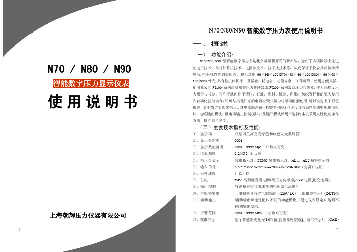
智能数字压力显示仪表上海朝辉压力仪器有限公司N70 / N80 / N90 使用 说 明书N70/N80/N90智能数字压力表使用说明书一、概述(一) 功能介绍:N70/N80/N90型智能数字压力表是我公司最新开发的新产品,融汇了多项国际上先进的电子技术、单片计算机技术、电擦除技术、抗干扰技术等,从而保证了仪表具有测控精度高,抗干扰性能强等优点。
整机选用96×96×100(N70)/48×96×100(N80)/ 96×48×100(N90)外壳,具有整机体积小、重量轻、耗电省、功能齐全、工作可靠、使用方便灵活,配用我公司PT100-系列高温熔体压力传感器或PT200-系列常温压力传感器,作为高精度压力测量与控制,可广泛地使用于液压、石油、塑料、橡胶、印染、纺织等行业的压力显示和自动化控制场合,还可与其他厂家的电阻应变式压力传感器配套使用;可以设定上下限值报警,具有发光管报警指示、继电器触点输出控制外部执行机构;具有高精度的电压输出模块、电流输出模块、继电器输出控制模块以及通讯模块供用户选择;本机采用人性化的操作方法,操作简单易学。
(二)主要技术指标及性能:⑴.显示器 双层四位高亮度绿色和红色发光数码管 ⑵.显示分辨率 0001⑶.显示数值范围 0001-9999 Mpa (小数点可变) ⑷.仪表精度 0.2%FS ± 1位⑸.指示灯显示 效准指示灯、FUNC 输出指示灯、AL1,AL2报警指示灯 ⑹.输入信号 2/3.3 mV/V 0-20mA/4-20mA/0-5V/0-10V (定货时说明) ⑺.采样速度 4 次/ 秒⑻.供电 +9V 高精度直流电源(配压力传感器)/24V 电源(配变送器) ⑼.输出控制 与满量程信号成线性的电压或电流输出⑽.主报警输出 上限报警具有继电器输出(220V 1A )上限报警指示灯(OUT)亮 ⑾. 辅助输出 辅助输出可通过配以不同的功能模块并通过仪表设定来达到不同的输出要求。
SMC压力表说明书(标准版)
SMC压力表说明书(标准版)尊敬的用户:感谢您选择本公司的压力表产品。
在使用本压力表前,请仔细阅读本说明书,以便正确地使用和维护压力表。
一、产品简介本压力表采用高精度传感器和先进的微处理器技术,具有测量准确、稳定可靠、操作简便等特点,适用于各种工业领域中的压力测量。
二、产品型号与规格1. 产品型号:SMC-YZ012. 量程范围:0-100MPa3. 精度等级:0.5级4. 工作电源:DC 3.6V5. 显示方式:LCD液晶显示6. 输出信号:RS485三、操作说明1. 开机:将压力表的电源开关拨至“ON”位置,等待约3秒后,压力表将自动开机。
2. 关机:将压力表的电源开关拨至“OFF”位置,等待约3秒后,压力表将自动关机。
3. 测量:将压力表的测量接口连接到待测压力源,压力表将自动测量并显示压力值。
4. 设置:通过按压压力表上的“SET”键,可进入参数设置模式。
在设置模式下,可通过按压“UP”和“DOWN”键调整参数值,然后按压“SET”键确认。
四、维护与保养1. 使用过程中,请勿让压力表受到撞击、摔打等强烈冲击,以免损坏压力表。
2. 请定期检查压力表的连接线、接头等部件,如有损坏或磨损,请及时更换。
3. 请定期清洁压力表的外壳和显示屏幕,保持压力表的清洁。
4. 请定期检查压力表的电池电量,当电池电量低于30%时,请及时更换电池。
五、注意事项1. 本压力表仅适用于测量压力,严禁用于其他目的。
2. 在测量过程中,请勿让压力表过载,以免损坏压力表。
3. 请勿擅自拆卸、改装压力表,如有需要,请与本公司联系。
4. 请妥善保管本说明书,以备日后参考。
六、附件1. 压力表x 12. 测量连接线x 13. 说明书x 1感谢您对本公司的支持,祝您使用愉快!如有任何问题,请随时与本公司联系。
联系电话:联系邮箱:公司网址:。
五岳PW系列智能数字压力表使用说明书
PW206智能数字压力表使用说明功能介绍欢迎您选用我公司生产的PW206智能数字压力仪表。
该说明书详细地介绍了PW206的性能特点、参数指标、使用方法、维护保养等内容。
使用前仔细阅读本说明书,以便您正确使用。
PW206是高性能智能压力测量控制仪表。
该表吸收了国内外同类仪表的优点,可与同类仪表直接互换配套使用,也可与3.3mv、2mv、4mv、1.5mv输出的传感器配套使用(供客户自选),它还特别适用于高温环境熔体压力的测量与控制。
该表外形美观、功能齐全、操作简单、并具有极好的抗干扰性能,使系统工作可靠。
该表采用双层四位数码管分别显示实际压力值和设定压力值;具有压力上、下限报警,并由继电器触点输出;两路报警、可恒流(可恒压)输出;4-20mA或0-10V等线性输出模拟量,可直接到PLC或其他控制器工作。
系统校准采用全自动面板调试;使系统校准只需简单一按即可完成。
该表采用了光电隔离技术、看门狗电路、软件滤波技术三种抗干扰措施,保证了系统可靠工作。
仪表采用开关电源供电,在电网120V低电压时也能正常工作。
该表与PT系统压力传感器配套使用,广泛应用于石油、化纤、塑胶等行业对高温熔体压力的测量与控制;也可与其他普通压力传感器配套使用,应用于常温状态的压力测量与控制。
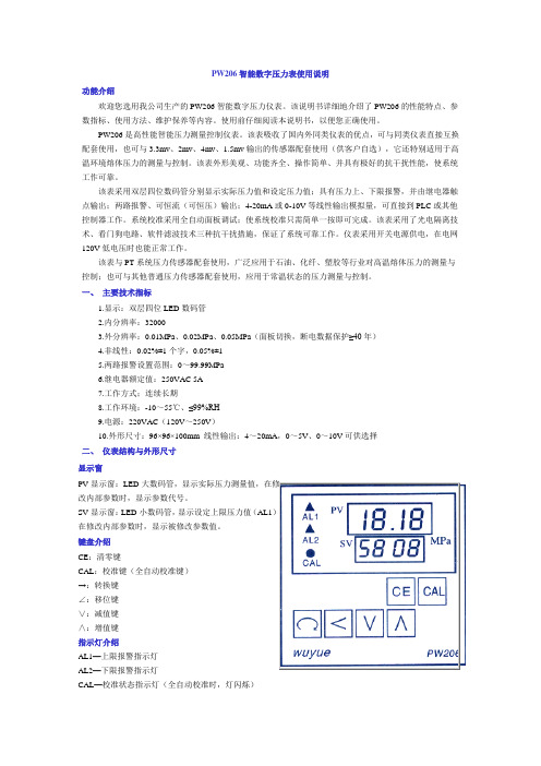
一、主要技术指标1.显示:双层四位LED数码管2.内分辨率:320003.外分辨率:0.01MPa、0.02MPa、0.05MPa(面板切换,断电数据保护≥40年)4.非线性:0.02%±1个字,0.05%±15.两路报警设置范围:0~99.99MPa6.继电器额定值:250VAC 5A7.工作方式;连续长期8.工作环境:-10~55℃、≤99%RH9.电源:220VAC(120V~250V)10.外形尺寸:96×96×100mm 线性输出:4~20mA,0~5V、0~10V可供选择二、仪表结构与外形尺寸显示窗PV显示窗:LED 大数码管,显示实际压力测量值,在修改内部参数时,显示参数代号。
Roctest Pencel 压力表使用说明书

INSTRUCTION MANUALPRESSUREMETERModel PENCELRoctest Limited 2016, 2018. All rights reservedThis product should be installed and operated only by qualified personnel. Its misuse is potentially dangerous. The Company makes no warranty as to the information furnished in this manual and assumes no liability for damages resulting from the installation or use of this product. The information herein issubject to change without notification.Tel. : 1.450.465.1113 • 1.877.ROCTEST (Canada, USA) • 33 (1) 64.06.40.80 (Europe) • • www.telemac.frTABLE OF CONTENTS1DESCRIPTION (1)2FILLING AND SATURATING THE PRESSUREMETER (2)3CALIBRATION (4)3.1PRESSURE LOSS CALIBRATION(PRESSURE CORRECTION) (5)3.2VOLUME LOSS CALIBRATION(VOLUME CORRECTION) (5)4PROBE INSERTION (6)5TESTING PROCEDURES (6)5.1VOLUME CONTROLLED TEST (6)5.2STRESS CONTROLLED TEST (6)6INTERPRETATION (7)6.1LIMIT PRESSURE (7)6.2DEFORMATION MODULUS (7)7PENCEL PROBE MEMBRANE REPLACEMENT (8)8APPENDIX (10)1DESCRIPTIONThe PENCEL pressuremeter is designed to perform pressuremeter tests using lightweight drilling equipment on sites where the use of heavy drill rigs are impractical. The probe is set in place by pressing it to the test depth or by direct driving from ground surface or from within a predrilled borehole.The PENCEL consists of three main elements:The probesHollow model:The hollow mono-cellular probe is comprised of a zinc plated steel tube on which an inflatable metallic sheath is mounted. The sheath is held in place using two tapered metal rings and two lock nuts. The probe is fitted with a quick disconnect at its upper extremity and a saturation plug at its lower extremity. The quick connect accepts the tubing leading from the pressure-volume control unit. The plug is used for saturating the probe. A drive point screws onto the lower end of the probe and an adaptor, which accepts EW or AW drill rod screws onto the upper end of the probe. The total length of the probe is 580 mm and its maximum deflated diameter is 32.1 mm which is slightly less than the diameter of a standard static penetrometer cone. The hollow center probe can be used in series with the static cone penetrometer.Solid model:The mono-cellular probe is comprised of zinc plated steel tube on which an inflatable metallic sheath is mounted. The sheath is held in place using two tapered metal rings and two lock nuts. The probe is fitted with quickdisconnects at both extremities. Oneaccepts the tubing leading from thepressure-volume control unit and the otheraccepts the saturation tubing. A drive pointscrews onto the base of the probe. Anadaptor which accepts EW or AW drill rodscrews onto the top of the probe.The Control UnitThe control unit consists of a ABS enclosuresupported on an aluminium tripod andcontaining a piston cylinder assembly,pressure gage, volume counter, controlvalves and tubing connectors.The TubingThe tubing consists of a single conduit fittedwith shut-off quick connectors at both ends,which allows the probe or tubing to bedetached without de-saturating the circuit.2FILLING AND SATURATING THE PRESSUREMETERA 1000 cm3 capacity container filled with clean water is required for this operation. Should any risks of freezing occur, the water must be replaced by windshield washer. THE UNIT SHOULD BE CLEANED WITH FRESH WATER WHEN NOT USED.Saturation of the Control Unit:1. Pressure gage adjustment. The pressure gage should read 0. If not, use the followingprocedures to set the needle to zero.∙Unscrew the knurled plug located at the upper back face of the pressure gage.∙Set the pressure gage needle to zero using a small screwdriver.∙Put back the knurled plug.(With Solid Probe Only)Front Panel of the 2500-kPa PENCEL Control Unit2.Connect the short tubing fitted with the male quick connect to the FILL-BLEED (1) porton the front panel.3.Place VALVE 3 in the FILL-BLEED position and VALVE 4 in the CLOSED position.4.Submerge the plain end of the filling tube in the container filled with water or theantifreeze mixture.5.Rotate the crank handle clockwise (i.e. in the INFLATE direction) to bring forward thepiston in its foremost position within the cylinder. The numerical volume counter will indicate 138 +/- 1 cm3 (or cc).6.Rotate the crank handle in the DEFLATE direction at a maximum speed of onerevolution per second until the volume counter indicates 0 cm3. The cylinder is now full of liquid.7.To remove air in the cylinder or in the tubing, transfer 100 cm3 from the cylinder backinto the container. To do so, rotate the crank handle in the INFLATE direction until the volume counter reads 100 cm3.8.Repeat step 6 to refill the cylinder.9.Connect the short hose to the PROBE (2)quick connect on the front panel. PlaceVALVES 3and 4in the TEST position. Rotate the crank handle in the INFLATE direction until air-free water flows out on the short hose. Disconnect the short hose from PROBE (2), and refill the unit following steps 3 and 6 above.10.The control unit is now fully saturated. The user can now check it and saturate the 10-m tubing and probe as indicated below.Saturation of the Tubing & Probe:11.Connect the tubing to the probe. Lay out the drive rods side by side in the propersequence for subsequent assembly. The rod couplings should alternate between male and female. The drill rod couplings should have been previously drilled out with an oversized hole of 16 mm in diameter to enable the passage of the male quick connect at the end of the tubing. Thread the tubing through the rod string beginning with the rod with a male coupling. Unscrew the drive point from the base of the probe. With the hollow probe, remove the cap on the saturation plug located at the base of the probe.With the solid probe, hook up the short tubing fitted with a female quick connect to the base of the probe.12.Connect the tubing to the PROBE (2) quick connect on the front panel.13.Place VALVE 3and VALVE 4in the TEST position. Rotate the crank handle in theINFLATE direction. During this operation, the probe must be held in an inverted vertical position with the center at the same height as the pressure gage of the control unit. In this position, the saturation plug points upward. A short hose should be connected to the solid Pencel probe for allowing water to flow out the probe – see image above. When using a hollow Pencel probe, simply remove the saturation plug at the tip of the probe.14.Stop cranking when air-free water flows out the probe. Place VALVE 4 in the CLOSEDposition and VALVE 3 in the FILL-BLEED position. Refill the cylinder by rotating the crank handle in the DEFLATE direction with a maximum speed of one revolution per second until the volume counter indicates 0 cm3, as described in step 6. Make sure that the free end of the filling tubing always remains submerged.15.Repeat last two steps until no air bubbles emerges from the saturation plug or tubing.16.For hollow probe: Screw the cap back onto the plug.For solid probe: Disconnect the short saturation tubing from the probe.Screw the drive point back onto the threads at the base of the probe.17.Disconnect the probe tubing from the front panel PROBE 2. The probe and the tubingcan then be transported in a saturated mode.Verifiaction of the Control Unit:18.Disconnect all tubing from the control unit. Place VALVE 3 and VALVE 4 in the TESTposition.19.Pressurize the cylinder until the pressure gauge reaches the maximum range. This isdone by turning the crank in the INFLATE direction. Verify that the volume necessary for this operation is less than 5 cm3, and also that after about two minutes, the pressure stabilizes.20.If the volume necessary to carry previous step is more than 5 cm3, the saturation of thesystem is inadequate. It is then necessary to bring back the pressure to zero and to repeat the saturation operations.21.If the pressure cannot be stabilized, there is a leak in the internal circuitry. Open theunit by removing the front panel and locate the leak by pressurizing the cylinder. Repair as required. The saturation must be repeated from the beginning and the volume counter must be brought back to 0.3CALIBRATIONTwo calibrations are required. One is the Pressure Loss Calibration and the other is the Volume Loss Calibration. The calibrations have the following purposes:1.To determine the pressure correction necessary to annul the inertia of the membrane.The inertia is the pressure required to dilate the probe to a specific volume when the probe is confined only by atmospheric pressure.2.To determine the volume correction caused by the parasitic expansion in the tesingunit. This is the small difference between the injected volume that is read on the meter and the real increase in volume of the probe.3.1PRESSURE LOSS CALIBRATION (PRESSURE CORRECTION)The pressure correction curve is also called the inertia curve of the probe membrane. To determine the pressure correction curve, proceed as follows:Make sure the whole system is saturated. Connect the probe to the control unit and place it vertically at ground level next to the unit. Place VALVE 3 and VALVE 4 in the TEST position, inflate and deflate the probe five times by injecting 90 cm3in order to knead a new membrane. When deflating the probe do not rotate faster than one rotation per second. 1.Rotate the crank handle clockwise at a rate of one revolution every 9 seconds, until 5cm3 have been injected.2.Stop the injection, wait 30 seconds and record the pressure, which corresponds to 5cm3 injection.3.Continue this procedure until 90 cm3 is injected.4.Slowly rotate the crank handle counter clockwise to bring the piston to its initialposition. The volume counter should indicate 0 cm3.The inertia curve is the plot of the pressure versus the injected volume. It is required for interpretation of the test data and must be established for each new membrane mounted on a probe. The inertia should also be verified at the beginning of a test and at regular intervals during testing procedures.3.2VOLUME LOSS CALIBRATION (VOLUME CORRECTION)The volume correction is required to correct the injected volume as read on the counter for the volume losses due to the system's intrinsic deformation under pressure. To determine the correction proceed as follows:1. Place VALVE 3and VALVE 4in the TEST position. Make sure the whole system issaturated. Connect the probe to the control unit and place it in a calibration tube such as the one supplied. The calibration can be any thick wall tube with an inside diameter of around 34 mm.2. Inflate the probe (in the tube) by injecting water in increments of 200 kPa. After awaiting period of 1 minute, record the pressure and volume for each increment.Continue to inject and record pressure up to 2000 kPa.3. Deflate the probe by bringing the volume counter back to zero.4. Plot Volume Calibration curve.Either one or both of the calibration tests described above should be performed when any one of the following conditions are met:-If a protective sheath is replaced.-If the same protective sheath has been used for a large number of tests, the calibration should be checked.-If the tubing has to be changed.-If the ambient temperature at the test location or in the borehole is substantially different from the temperature that prevailed during the last calibration.It should be emphasized that calibration tests are important if one wants to arrive at representative results. It is recommended to calibrate regularly.4PROBE INSERTIONThe PENCEL probe is set in place by pushing or light hammering. In this case, the probe is connected to hollow EW drill rods with an external diameter of 34.9 mm. The standard inside diameter of the coupling is reamed from 12.7 mm to 16 mm.The tubing beginning with the upper end, which connects to the control panel, is threaded from bottom to top through the rods. The diameter of the quick connect at the upper end of the tubing is 15 mm.Rods with an inside diameter of at least 16 mm may be used instead of EW rods. An EW male coupling must be fabricated for the connection to the probe. A slotted anvil adapted for the pushing or driving systems is screwed to the upper end of the rods. The slot allows the passage of the tubing.Do not forget to put a locking ring on the quick connector between the probe and the tubing for avoiding accidental disconnection of the probe in the ground.Another option consists in making the test cavity by driving a 35-mm OD steel rod. The rod is then removed and the probe is inserted.In dense soils, the probe could be damaged by the driving. A pilot hole of 35 mm Ø can be drilled.5TESTING PROCEDURES5.1VOLUME CONTROLLED TESTOnce the probe has been set at the test depth and VALVE 3 and VALVE 4 are in the TEST position, the testing can then be carried out in increments of equal volume. The increment of increasing volume is 5 cm3and the corresponding pressure is noted 30 seconds after having injected the 5 cm3. The maximum volume injected is 90 cm3. This results in a test with 18 volume increments and test duration of about 10 minutes.It is possible to carry on cyclic load cycles during a test, by injecting and then withdrawing a preselected volume of liquid (by deflating the probe).When the test is complete, prior to either removing the probe from the hole or pushing it toa lower level the probe must be deflated by returning the water to the cylinder.5.2STRESS CONTROLLED TESTThis method is more difficult to execute. It may be used for tests in over consolidated soil or during creep test.1.Lower the probe to the test depth.2.Place VALVE 3 and VALVE 4 in the TEST position.ing the crank handle, set the pressure gage reading to the first pressure stepcorresponding to less than 1/10 of the estimated limit pressure.4.Maintain the pressure at this value and record the counter readings, 30 seconds, 60seconds after the pressure step has been reached.5.When the loading phase of the test is completed, return the piston to its initialposition by turning the crank handle counter clockwise at a slow rate until the counter indicates 0 cm3.6INTERPRETATIONThe first step of the interpretation consists in plotting the raw pressuremeter curve (pressure vs volume) as well as the corrected pressuremeter curve. For each point on the raw curve there corresponds a point on the corrected curve with coordinates of corrected pressure and corrected volume. The corrected point is obtained by subtracting the volume correction and the pressure correction from the raw pressure and volume data. The corrected pressure must also include the hydrostatic pressure equivalent to the head of liquid between the pressure gauge and the center of the probe.Thus:V corrected = V read - V calibrationP corrected = P read - P calibration + P hydrostaticCalculations can be done based on the normal pressuremeter procedures. This gives: The limit pressure P lThe deformation modulus ENOTE: ASK ROCTEST FOR A FREE COPY OF PENCELCOMPANION : A SPREADSHEETFOR DATA REDUCTION6.1LIMIT PRESSUREThe limit pressure is not necessarily modified by remoulding of the ground due to the driving of the probe. Theoretically the limit pressure corresponds to that required to double the initial volume Vo of the probe, which in the case of the PENCEL probe corresponds to a theoretical volume of 192 cm3 and an inflated diameter of 45 mm. The limit pressure is obtained by extrapolating the corrected pressuremeter curve beyond the injected volume of 90 cm3.6.2DEFORMATION MODULUSThe modulus E is calculated in the pseudo-elastic phase of the test. This corresponds to the quasi-linear part of the pressuremeter curve.E = 2 (1 + µ) (Vo + Vm) (P2-P1)(V2-V1)where:µ = Poisson's ratio = 0.33Vo = initial probe volume = 192 cm3Vm = the mean volume injected at midpoint of the linear part of the curve for which the modulus is calculated.P2-P1 = increase of pressure P corresponding to the increase of volume V2-V1 Example:If the curve is linear between 30 and 60 cm3 and the values are as follows:V1 = 30 cc P1 = 200 kPaV2 = 60 cc P2 = 1000 kPaThen:Vm = V1 + V2 = 45 cm3 V2-V1 = 30 cc P2-P1 = 800 kPa2E = 2.66 (192 + 45) 800 = 16 819 kPa30Due to soil disturbance, the modulus value obtained with a driven probe may be slightly different from a value obtained by placing the probe in a drilled hole. For example, the values obtained in saturated granular materials at depths greater than 10 meters are either the same or less than those obtained in drill holes.For more information about the test itself and the treatment of the modulus and limit pressure values, the reader is referred to the different manuals and books bearing the subject, especially the ASTM standard D4719–00 and the Note D.60.AN available from Roctest.7PENCEL PROBE MEMBRANE REPLACEMENT1.Unscrew the two brass knurled nuts.2.Place the threaded end of the probe in the bench vice adapter or grasp with plasticcovered jaws in order to prevent damage to the thread.3.Remove the plain tapered ring at the free end of the probe by rotating the ringclockwise while pulling at the same time. If not possible to do by hand, wrap astrap wrench around the knurled part of the ring. A pipe tube wrench should notbe used, due of the danger of deforming the ring.4.Repeat the same operation on the ring at the other end of the probe.5.Remove the membrane.6.Place a new membrane and center it over the body of the probe.7.Tighten a hose clamp at a distance of 2 cm from the end of the metallic strips toenable the tapered ring to slide over the beginning of the strips.8.Grease the inside of the tapered ring and the tape covering the end of the metallicstrips with a very small amount of silicone base grease.9.Push the tapered ring over the end of the metallic strips until the threads on theprobe are visible. Thread the brass-knurled nut onto the end of the probe.10.Repeat steps 7, 8 and 9 for the other end of the probe.11.Check that the membrane is well centred lengthwise over the probe. Position thetapered rings as required to center the membrane by screwing the brass nuts inwards or outwards.12.Screw in the brass nuts with a strapped wrench in equal amounts until thedistance between the inside edge of the steel rings is 24 cm. At this point about2.5 cm of thread will be showing at both ends of the probe.13.The probe is now ready for calibration.8 APPENDIXProbe Components and AccessoriesA Probe to AW rod adapter 20-1026002032B Probe to EW rod adapter20-1026002039 C Hollow PENCEL Probe 2500 kPa (assembled) FR-1026050300 D Saturation Plug for the Hollow PENCEL Probe 05-R03LA3C E Quick Connect Locking Ring20-1026002033 F Tubing with fittings to connect solid probe to control unit, 10 m length 40-1026040700 G PENCEL solid probe 2500 kPa (assembled) FR-1026050200 H Drive Point for hollow/solid probe 20-1026002030/38 I Probe to bench vice adaptor20-1026002040 J PENCEL solid probe 2500 kPa Body with Swagelok quick connector 20-1026002035 K Pencel Metallic sheath40-1026040600 L Sheath external Ring for 2500 kPa probe 20-1026002034 MCover Nut for probe20-1026002037ABCDEGHiJKLMF。
压力表限位和阀门标识

1目的
通过贴标识,使压力表和阀门开关一目了然,任何人都能立即判别设备的状态
是否正常并能及时处理。
2范围
公司内所有的压力表和阀门。
3标识规定
3.1压力表限位标识
3.1.1统计压力表表盘直径,根据表盘直径确定压力表限位标识线的大小和数量。
3.1.2根据表盘幅度定制相应的压力表限位标识线。
3.1.3压力表限位标识线分两种类型,正常范围和异常范围:正常范贴绿线,异常范围贴红线,标识时要求紧靠表盘边缘,红线长度需相同。
3.1.4压力表限位标识线大小分3mm和5mm。
表盘直径在50mm以下用3mm限位标识线,表盘直径在50mm以上用5mm限位标识线。
3.1.5进行压力表限位标识时,压力表一定要干净整洁。
3.1.6附图
3.2阀门开关标识
3.2.1圆盘型阀门开关标识
3.2.1.1统计阀门的内直径和外直径,确定阀门标识的大小和数量。
3.2.1.2根据阀门内外直径的大小定制相应的阀门开关标识。
3.2.1.3将阀门开关标识贴在阀门中央的螺丝周围。
3.2.1.4附图。
压力表使用规范(最新版)

压力表使用规范为加强在用压力表的管理,确保压力表完好,规范压力表的使用,制定如下规定,望认真执行;1.压力表的选用1.1选用的压力表,应当与压力容器、管道内的介质相适应。
1.2设计压力小于1.6MPa压力容器、管道使用的压力表精度(注1)不得低于2.5级;设计压力大于或者等于1.6MPa压力容器、管道使用的压力表精度不得低于 1.6级。
1.3工艺用压力表(注2)表盘刻度极限值应为最大允许工作压力(注3)的 1.5-3.0倍,最好取2倍左右。
在满足工艺要求的条件下优先选用外壳公称直径100mm的压力表(很重要)。
---压力表选型依据1.4压力表在测量稳定负荷时不得超过量程的2/3,测量波动压力时,不应超过量程的1/2,至于最低压力,在以上两种情况下,均不应低于量程的1/3。
---压力表选型依据2.压力表的校验2.1压力表安装前应进行校验,然后每隔半年校验一次。
2.2需要强检的压力表由设备科负责外出校验,校验后的压力表应将检验标志贴在表盘上,并注明下次校验日期或有效期。
2.3非强检的压力表可根据检定的压力表进行自校,并做好自校记录。
3.压力表的安装要求3.1装设位置应便于操作人员观察和清洗,且应避免受到辐射热,冻结或振动的不利影响。
3.2压力表与压力容器、管道之间,应装设三通旋塞或针型阀;三通旋塞或针型阀应有开启标记;压力表与压力容器、管道之间,不得连接其他用途的任何配件或接管。
3.3用于蒸汽介质的压力表,在压力表与压力容器、管道之间应装有存水弯管。
使蒸汽在这一段弯管内冷凝,以避免高温蒸汽直接进入压力表的弹簧管内,致使表内元件过热而产生变形,影响压力表的精度。
存水弯管用钢管时,其内径应不小于10mm。
3.4用于高温、具有腐蚀性或高粘度介质的压力表,在压力表与压力容器、管道之间应装设能隔离介质的缓冲装置。
3.5专用的特殊压力表,严禁他用,也严禁在没有特殊可靠的装置上进行测量,更严禁用一般的压力表作特殊介质的压力测量。
数字压力表使用说明书

YS-100型数字压力表使用维护说明书本数字压力表结合了世界领先的微处理技术和先进的模数转换算法,达到高精度,低功耗的要求。
采用大屏幕的液晶显示技术,使数据清晰易读。
独特的背景灯技术夜晚也能正常使用,采用进口芯片,对仪表数据采集、记忆、测量保持最高峰值,手动回零,外壳采用不锈钢,耐腐蚀,抗机械压力,机体整体采用密封技术,可以应用在多种复杂的环境中。
陶瓷传感器经久耐用,安全卫生,可应用在食品卫生行业。
本产品是国外名牌数字压力表的中国OEM产品,拥有和国外数字压力表同样性能,是替代传统机械表的理想选择。
一工艺特性●电气特性:工作电源:3.6VDC; 功率消耗:100微瓦工作温度:-20℃~+80℃ -40℃~+80℃工作湿度:10%~90%(不凝结);连续工作时间:大于3年精度等级:0.25%;0.5%;1%;测量范围:0~100Mpa(可选);0~5Kpa~600Kpa (可选);真空:-100Kpa~0Kpa(可选)-0.1~ 0 Mpa压力真空:-0.1~2.4Mpa(可选);- 100~2400Kpa压力单位可选:Mpa 、Kpa、Kgf/cm2、Bar、mBar、PsiKN、mmAq mmHo、Torr mmhg、atm(特殊要求可定做成Psi、Mpa 、Kpa自由切换)屏幕信息量:4位9段; 报警输出电压:2.7V-3.0V(5mA)●机械特性振动特性:40g(最大);4g(最大)15-200Hz外形尺寸:主要用途:1、油田注水,井口容器设备压力测量:2、原油外输:动力设备管道泵进出口压力测量;3、石油化工:生产工艺中的真空,微压及腐蚀性的气体,液体压力测量;4、液压系统、制冷、过程监控OEM应用;5、高温介质,粘稠介质,液体高度测量;6、空调、气体处理设备、呼吸机、医疗设备、实验室、压缩机等压力的测量;二操作说明本产品的传感器与显示处理部分采用一体化的设计结构,使用简便,该仪表与被测机构使用螺纹直接连接的方式,对仪表的摆放角度不做任何要求。
压力表使用警示标识要求(dgy)

压力表使用警示标示管理
1、要求出处
《TSG21-216固定式压力容器安全技术监察规程》第9.2.1.2条“压力表的检定和维护应当符合国家计量部门的有关规定,压力表安装前应当进行检定,在刻度盘上应当划出指示工作压力的红线,注明下次校验日期。
压力表校验后应当加铅封。
”
5S可视化管理,限度标识
2、压力表使用警示标识
(1)第一种:
说明:
a、要求各部门严格按照规定选择压力表量程(最大工作压力的
1.5-3.0倍)。
b、压力表警示标志适用于压力表的现场标识,可以使用彩色油漆,也可以采用彩色自粘胶带进行粘贴,限位标识尺寸30×(2-3)mm,自圆心开始沿半径方向黏贴喷涂,严禁覆盖表针及数字;压力表的自身限位标识尺寸Ø85/Ø75mm,不能覆盖刻度线,采用红色。
同时要求绿色初始位置标志不能低于量程的1/3,红色上限警示标志不能超过量程的2/3。
(2)第二种:
说明:
a、用红黄绿三色标明仪表工作范围;仪表工作范围根据工艺指标定;
b、红色区域:异常值范围;黄色区域:报警范围;绿色区域:正常运转值范围;
c、标识线宽为5mm。
压力表使用说明
使用说明
1、仪表执行(GB/T1226-一般压力表)国家标准。
2、仪表接头螺纹径向为M14×1.5(Y60)、M20×1.5(100、Y150、Y200、Y250)。
3、仪表正常工作环境温度为-40℃~70℃。
4、仪表安装点和测定点应在同一水平上,否则应加校正值,但与测量气体无关。
通常连接
导管的长度不超过50米。
5、为减少冲击、震动和被测介质急剧变化对仪表的影响,使用时须添置各种缓冲器。
6、仪表适用测量对钢和铜合金无腐蚀性介质的压力。
7、仪表在测量稳定压力时,一般使用至测量上限的3/4,测量波动压力时,一般不超过测
量上限的2/3。
8、使用时的仪表,每六个月检验一次。
数字压力表使用说明书
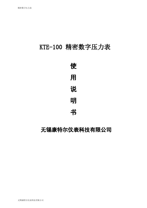
短按
键,可以打开/关闭屏幕背光,颜色为白色;背光的点亮时长可进行设定,详见
设定界面功能说明;如设定背光时间为常亮时,只有再次按下“背光”键,背光才熄灭。
3、压力清零
把 压 力 表 的 引 压 口 通 大 气 , 如 果 当 前 压 力 测 量 数 值 在 ± 1%FS 范 围 内 时 ,
长按
键保持约 3 秒,可对测量数值清零。
该产品采用微处理器对仪表零点漂移,非线性等进行自动补偿、修正,采用高稳定度 压力传感器等高性能器件,确保仪表精度和可靠性。该仪表可自行设定各种功能参数,应用 灵活,且有各种功能可选定,可用作较高准确度压力校准标准器(表),也可用作工作仪表、 电力、冶金、石油、化工等行业实验室和现场进行计量和科研。
二、技术参数
无锡康特尔仪表科技有限公司
精密数字压力表
一、产品简介
1、产品特点 1)可随时随地根据用户需求进行各种参数的设定,应用灵活、方便。 2)可根据用户要求量身定做特殊功能压力表。 3)软件进行温度补偿,精度高,使用温度广。 2、概述
KTE-100 精密数字压力表采用高精度低功耗大规模集成电路为核心器件,主要由高精度 测量芯片、电池充电保护电路、传感器和信号处理电路组成。
统。 公司成立以来凭借良好的信誉及优质的服务已经与各地区的生产厂商建立了 长期稳定的商业贸易伙伴关系。 公司坚持“科技、创新、质量、服务”的发 展方针,继续秉承“打造产业航母、贡献民族经济”的宗旨,把“康特尔”建设 为国际品牌企业。 本公司的流量计、压力仪表、物位仪表、温度仪表、校验仪 表、智能数显仪表等以优惠的价格、优良的服务积极参与市场竞争。
无锡康特尔仪表科技有限公司
精密数字压力表
三、仪表显示面板及功能键
压力表说明书(共5篇)
篇一:压力表说明书弹簧式压力表一、压力表的结构与原理锅炉上普遍使用的是弹簧管式压力表,主要由弹簧弯管、连杆、扇形齿轮、小齿轮、中心轴、指针、表盘等构件组成,如图所示。
弹簧弯管是由金属管(无缝铜管或无缝钢管)制成的。
管子截面呈扁圆形或椭圆形,它的一端是封闭的自由端,与杠杆连接。
杠杆的另一端连接扇形齿轮,扇形齿轮又与中心轴上的小齿轮相啮合,压力表的指针固定在中心轴上。
当弹簧弯管受到介质压力的作用时,它的截面有变成圆形的趋势,迫使弹簧弯管逐渐伸直,从而使弹簧弯管的自由端向上翘起。
压力越高,自由端向上翘起的幅度越大。
这一动作经过杠杆、扇形齿轮、小齿轮的传动,使指针偏转一个角度,在刻度盘上指示出压力高低。
当被测介质压力降低时,弹簧管要恢复原状,指针退回到相应刻度处。
在燃油(气)锅炉上还有一种使用较多的是电接点压力表。
电接点压力表是在普通弹簧管压力表上加装一套高低限电接点装置构成的。
它不但能随时测量介质压力变化情况,而且还能将被测介质保持在一定压力范围内,当被测压力超过这一范围时,能自动发出报警信号。
电接点压力表也可带继电器及接触器的电气线路,获得自动控制信号,通过控制机构,使被测介质的压力自动保持在上下限给定值的范围内。
三、压力表精度弹簧管式压力表的精度等级,是以允许误差占压力表量程的百分率来表示的,一般分为0.5、1、1.5、2、2.5、3、4七个等级(锅炉上不用3级和4级),数值越小,其精度越高。
例如,表盘量程0~2.5mp,精度2.5级的压力表,它的指针所示压力值与被测介质的实际压力值之间的允许误差,不得超过上 2.5mpa ×2.5%=±0.0625mpa;当压力表指示压力为0.8mpa时,实际气压在0.7375~0.862 5mpa之间。
篇二:压力表的结构图与说明压力表的结构图与说明压力表的设置原理为什么压力表要这样设置。
事实上是基于这样一个原理:压力表通过表内的敏感元件(波登管、膜盒、波纹管)的弹性形变,再由表内机芯的转换机构将压力形变传导至指针,引起指针转动来显示压力。
计量器具标识填写粘贴规范

计量器具标识填写粘贴规范
计量器具标识填写粘贴规范
根据9月23日局安全检查组在我公司检查时对计量器具规范管理提出的整改意见,结合我公司实际情况特制订计量器具标识填写粘贴规范
一、凡已经检定登记在帐的计量器具都要粘贴合格标识,
二、标识内容规范:
1、编号填写必须与计量器具上的编号一致;
2、确认时间按照 ****年**月**日格式填写;(如2011年9月28日,不得写成11年9月28日)
3、确认专责人填写为本部门计量管理员;
4、必须使用黑色或蓝色水笔填写,严禁使用圆珠笔填写;
5、书写须工整;
三、标识粘贴位置:
1、压力表:一般情况下应粘贴在仪表侧面左上部分,根据仪表样式及现场安装情况需要也可粘贴在仪表其他地方,但不得粘贴在仪表表盘玻璃上以免影响查看数据。
鉴于我公司实际情况,标识粘好后应用宽透明胶带覆盖标识粘贴在仪表上,以免标识脏污或脱落。
2、电气仪表:一般情况下应粘贴在仪表正上方电气柜板上,根据仪表样式及现场安装情况需要也可粘贴在仪表其他地方,但不得粘在仪表表盘玻璃上以免影响查看数据。
3、其他计量器具:一般情况下应粘贴与器具正面醒目位置但不得影响器具显示及观测读数。
现场环境较差的应当用透明胶带覆盖粘贴。
压力表检定标签

压力表检定标签
摘要:
1.压力表检定的重要性
2.压力表检定标签的作用
3.压力表检定标签的内容
4.压力表检定标签的粘贴规范
5.压力表检定的注意事项
正文:
【压力表检定的重要性】
压力表是工业生产中常用的一种测量设备,用于测量流体或气体的压力。
在工业生产中,压力表的准确性直接关系到生产过程的安全和产品质量。
因此,定期对压力表进行检定是非常重要的。
【压力表检定标签的作用】
压力表检定标签是标记压力表检定结果的重要标志。
它记录了压力表的检定日期、检定单位、检定结果等信息,方便用户了解压力表的检定情况,保证压力表的准确性和可靠性。
【压力表检定标签的内容】
压力表检定标签应包含以下内容:
1.压力表的型号和规格;
2.检定单位和检定人员;
3.检定日期和下次检定日期;
4.检定结果,包括测量上限、下限和精度等级;
5.检定标签的编号或序列号。
【压力表检定标签的粘贴规范】
压力表检定标签应粘贴在压力表的明显位置,方便用户查看。
同时,应保证检定标签的粘贴牢固,不易脱落。
在粘贴检定标签时,应注意避免遮挡压力表的刻度盘和指针。
【压力表检定的注意事项】
1.压力表应在检定周期内进行检定,超过检定周期的压力表应视为不合格,禁止使用;
2.检定压力表时应选择具有资质的检定单位和检定人员;
3.检定过程中,应注意保护压力表,避免因操作不当造成压力表损坏;
4.在使用压力表时,应遵循压力表的使用说明书,确保压力表的准确性和安全性。
总之,压力表检定标签是记录压力表检定结果的重要标志,它有助于保证压力表的准确性和可靠性。
压力表贴上下限宣传稿

压力表贴上下限宣传稿
尊敬的各位领导、各位同事:
大家好!今天我在这里向大家推介一种可以有效减轻压力的新产品——压力表贴上下限。
随着现代社会的高速发展和工作压力的不断增加,人们的压力问题越来越严重。
长时间高强度的工作压力不仅会导致身体机能下降、免疫力减弱,还会引发心理问题,甚至导致慢性疾病,对个人的身心健康产生巨大的威胁。
为了帮助大家有效缓解压力,我们研发了这一款压力表贴上下限产品。
它的原理非常简单,就是通过在压力表贴上设定一个个人认为最低合适的压力下限和上限,当达到上下限之间的压力时,产品将会发出提醒,提醒用户调整自己的心理状态和工作节奏,以保持身心状态的平衡。
这款产品有以下几个优点:
一、简单实用:产品通过贴在手腕上的方式使用,无需额外携带,使用方便简单,随时可以调整上下限。
二、个性化设置:每个人的心理承受能力和压力阈值都不同,产品允许用户根据自身情况设定心理压力上下限,更加符合个人需求。
三、提醒功能:产品能够提醒用户及时调整自己的心理状态,
防止过度压力和疲劳,保持身心健康。
四、健康宣传:通过推广这一产品,能够更好的宣传压力对身心健康的威胁,引导人们更加关注自己的压力状态和重视保持身心健康。
为了让更多的人能够了解和受益于这一产品,我们计划在各大公司、学校、医院等场所进行推介活动,并为愿意合作的单位提供优惠购买机会。
现在,我们真诚地邀请各位领导、各位同事一起共同努力,帮助更多的人缓解压力、保持健康。
让我们携手合作,共同为预防压力带来的各种问题而努力!
谢谢大家!。
- 1、下载文档前请自行甄别文档内容的完整性,平台不提供额外的编辑、内容补充、找答案等附加服务。
- 2、"仅部分预览"的文档,不可在线预览部分如存在完整性等问题,可反馈申请退款(可完整预览的文档不适用该条件!)。
- 3、如文档侵犯您的权益,请联系客服反馈,我们会尽快为您处理(人工客服工作时间:9:00-18:30)。
压力表标示贴使用说明
一、根据设备上压力表的量程和设备正常工作时的
压力范围划分颜色区域。
例如:右图中压力表量程为0-
1.6MPa,该压力表使用在化糖锅上。
化糖锅正常工作时,
压力范围在:0.4-0.8MPa(即4-8公斤压力)。
那么,
0-0.4MPa为黄色区域,表示压力偏低。
0.4-0.8MPa 为绿色区域,表示压力正常。
0.8-1.6MPa为红色区域,表示压力过高。
(此事例仅供参考,以现场实际情况为准)
二、根据上面的颜色区域,将标示贴裁剪
合适长度。
三、将裁减好的标示贴贴到压力表对应的量程上。
注:1、压力表表面直径为10cm。
2、压力表使用在熬糖锅,化糖锅,储气罐等压力容器上。
符合上述两条的压力表可用此标示贴。
