伊顿S811软启动器
Schneider Electric ATS01N212RT软启动器数据手册说明书

T h e i n f o r m a t i o n p r o v i d e d i n t h i s d o c u m e n t a t i o n c o n t a i n s g e n e r a l d e s c r i p t i o n s a n d /o r t e c h n i c a l c h a r a c t e r i s t i c s o f t h e p e r f o r m a n c e o f t h e p r o d u c t s c o n t a i n e d h e r e i n .T h i s d o c u m e n t a t i o n i s n o t i n t e n d e d a s a s u b s t i t u t e f o r a n d i s n o t t o b e u s e d f o r d e t e r m i n i n g s u i t a b i l i t y o r r e l i a b i l i t y o f t h e s e p r o d u c t s f o r s p e c i f i c u s e r a p p l i c a t i o n s .I t i s t h e d u t y o f a n y s u c h u s e r o r i n t e g r a t o r t o p e r f o r m t h e a p p r o p r i a t e a n d c o m p l e t e r i s k a n a l y s i s , e v a l u a t i o n a n d t e s t i n g o f t h e p r o d u c t s w i t h r e s p e c t t o t h e r e l e v a n t s p e c i f i c a p p l i c a t i o n o r u s e t h e r e o f .N e i t h e r S c h n e i d e r E l e c t r i c I n d u s t r i e s S A S n o r a n y o f i t s a f f i l i a t e s o r s u b s i d i a r i e s s h a l l b e r e s p o n s i b l e o r l i a b l e f o r m i s u s e o f t h e i n f o r m a t i o n c o n t a i n e d h e r e i n .Product data sheetCharacteristicsATS01N212RTsoft starter for asynchronous motor - ATS01 -12 A - 460..480 VProduct availability: Stock - Normally stocked in distribution facilityMainRange of product Altistart 01Product or component typeSoft starterProduct destination Asynchronous motors Product specific applica-tionSimple machine Device short name ATS01Phase3 phase[Us] rated supply volt-age460...480 V - 10...10 %Maximum Horse Power Rating7.5 hp, 3 phase 460...480 V IcL starter rating 12 AUtilisation category AC-53B EN/IEC 60947-4-2Current consumption 60 A at nominal load Type of startStart with voltage rampPower dissipation in W4 W at full load and at end of starting 124 W in transient stateComplementaryAssembly style With heat sink Function available Integrated bypass Supply voltage limits 414…528 V Supply frequency 50...60 Hz - 5...5 %Network frequency 47.5...63 HzOutput voltage<= power supply voltage [Uc] control circuit voltage Built into the starter Starting timeAdjustable from 1 to 10 s Deceleration time symb Adjustable from 1 to 10 sStarting torque 30...80 % of starting torque of motor connected directly on the line supply Discrete input type Logic LI1, LI2, BOOST) stop, run and boost on start-up functions <= 8 mA 27kOhm Discrete input voltage 24...40 VDiscrete input logic Positive LI1, LI2, BOOST < 5 V <= 0.2 mA > 13 V, >= 0.5 mA Discrete output current 2 A DC-133 A AC-15Discrete output type Open collector logic LO1 end of starting signal Relay outputs R1A, R1C NO Discrete output voltage 24 V 6...30 V) open collector logic Minimum switching current 10 mA 6 V DC relay outputsMaximum switching current Relay outputs 2 A 250 V AC cos phi = 0.5 20 ms inductive Relay outputs 2 A 30 V DC cos phi = 0.5 20 ms inductive Display type 1 LED green)starter powered up1 LED yellow)nominal voltage reached Tightening torque16.82…22.13 Lbf.In (1.9…2.5 N.m)4.43 lbf.in (0.5 N.m)Electrical connection 4 mm screw clamp terminal - rigid 1 1...10 mm² AWG 8 power circuitScrew connector - rigid 1 0.5...2.5 mm² AWG 14 control circuit4 mm screw clamp terminal - rigid 2 1...6 mm² AWG 10 power circuitScrew connector - rigid 2 0.5...1 mm² AWG 17 control circuitScrew connector - flexible with cable end 1 0.5...1.5 mm² AWG 16 control circuit4 mm screw clamp terminal - flexible without cable end 1 1.5...10 mm² AWG 8power circuitScrew connector - flexible without cable end 1 0.5...2.5 mm² AWG 14 control cir-cuit4 mm screw clamp terminal - flexible with cable end 2 1...6 mm² AWG 10 powercircuit4 mm screw clamp terminal - flexible without cable end 2 1.5...6 mm² AWG 10power circuitScrew connector - flexible without cable end 2 0.5...1.5 mm² AWG 16 control cir-cuitMarking CEOperating position Vertical +/- 10 degreeHeight 4.88 in (124 mm)Width 1.77 in (45 mm)Depth 5.16 in (131 mm)Net weight0.93 lb(US) (0.42 kg)Compatibility code ATS01N2EnvironmentElectromagnetic compatibility Conducted and radiated emissions level B CISPR 11Conducted and radiated emissions level B IEC 60947-4-2Damped oscillating waves level 3 IEC 61000-4-12Electrostatic discharge level 3 IEC 61000-4-2EMC immunity EN 50082-1EMC immunity EN 50082-2Harmonics IEC 1000-3-2Harmonics IEC 1000-3-4Immunity to conducted interference caused by radio-electrical fields level 3 IEC61000-4-6Immunity to electrical transients level 4 IEC 61000-4-4Immunity to radiated radio-electrical interference level 3 IEC 61000-4-3Micro-cuts and voltage fluctuation IEC 61000-4-11Voltage/current impulse level 3 IEC 61000-4-5Standards EN/IEC 60947-4-2Product certifications ULB44.1-96/ASME A17.5 for starter wired to the motor delta terminalCSACCCC-TickGOSTIP degree of protection IP20Pollution degree 2 EN/IEC 60947-4-2Vibration resistance 1 gn 13…150 Hz)EN/IEC 60068-2-61.5 mm peak to peak 3…13 Hz)EN/IEC 60068-2-6Shock resistance15 gn 11 ms EN/IEC 60068-2-27Relative humidity5…95 % without condensation or dripping water EN/IEC 60068-2-3Ambient air temperature for operation14…104 °F (-10…40 °C) without)104…122 °F (40…50 °C) with current derating of 2 % per °C)Ambient air temperature for storage-13…158 °F (-25…70 °C) EN/IEC 60947-4-2Operating altitude<= 3280.84 ft (1000 m) without> 3280.84 ft (1000 m) with current derating of 2.2 % per additional 100 m Ordering and shipping detailsCategory22392 - ATSU01/ATS01 LOW HP SOFT STARTERSDiscount Schedule I11GTIN00785901588337Package weight(Lbs)0.50 kg (1.11 lb(US))Returnability YesCountry of origin DEOffer SustainabilityREACh Regulation REACh DeclarationREACh free of SVHC YesEU RoHS Directive Pro-active compliance (Product out of EU RoHS legal scope)EU RoHS Decla-rationToxic heavy metal free YesMercury free YesRoHS exemption information YesChina RoHS Regulation China RoHS DeclarationCircularity Profile End Of Life InformationWEEE The product must be disposed on European Union markets following specificwaste collection and never end up in rubbish bins.Contractual warrantyWarranty18 monthsDimensions DrawingsDimensionsMounting on Symetrical (35 mm) RailScrew Fixing(1)Retractable fixingsConnections and Schema Example of Manual ControlA1 :Soft start/soft stop unit(1)For type 2 coordinationQ1 :Motor circuit-breakerF3 : 3 fast-acting fusesTechnical DescriptionFunction Diagram2-wire Control with DecelerationUs :Power supply voltageGreen LEDLED1 :LI2 :Logic inputR1 :Relay outputLO1 :Logic outputLEDYellow LED2 :3-wire Control with DecelerationUs :Power supply voltageGreen LEDLED1 :Logic inputsLI2,LI1 :R1 :Relay outputLO1 :Logic outputUm :Motor voltageLEDYellow LED2 :。
SIEMENS 3RW34 电子式软起动器 用户说明书

用户指导手册
1
危险电压 危害生命和重伤身体 或损坏财产
危险
在进行维修工作之前,必须彻底而全部地断开软起动器并将其 接地。在安装、投运或维修软起动器之前,必须阅读和理解这 本使用手册。只允许具有职业资格的人员进行维修工作。在维 修软起动器时使用不允许的零部件或者让无职业资格的人员去 检修软起动器就有可能导致人员死亡、重伤、损坏软起动器或 财产损失。必须遵守本手册中所述的安全守则以及有关的标准。
4.3 安装时的安全措施 ................................................ 13
4.4 布线总则 .............................................................. 14
4.5 电网连接和电动机连接 ......................................... 19
表格的目录
表格
页
1 在 TU = 40°C 时的电动机额定功率 (kW) ................. 10
2 在 TU = 50°C 时的电动机额定功率 (Hp) .................. 11
3 在 TU = 60°C 时的电动机额定功率 (kW) ................. 12
6 电动机在降压时的典型转速 / 转矩 - 特性曲线 ............ 8
7 在软起动与自然制动直至停止运转时,以时
间为函数的电压与转速-特性曲线 ........................... 9
8 在软起动与软制动时的电压和转速特性曲线 ............. 9
9 电感性用电设备的去干扰 ......................................... 16
Eaton S811+ S801+软启动器系列数据表说明书

Advanced intelligence. Compact footprint.High-performance family The Eaton S811+/S801+ soft starter family delivers solid performance beyond standard protection features found in most soft starters. Choosing a soft starter will increase your productivity and reduce your costs by:•Eliminating abrupt starts and stops, extending mechanical life of system•Better control of motor torque, increasing gearbox and bearing life, reducing belt wear and eliminating water hammer• Lowering inrush, reducing peak demand charges • Reducing brownouts and decreasing overall energy usage• Integrating overload protection •Reducing number of devices, panel size, installation time and assembly costs withinternal run bypass contactorsS811+ key featuresCompact, easy to program and easy to install, the S811+ line of soft starters is ideally suited for open, enclosed and motor control center (MCC) applications. Ranging from 11 A to 1000 A, the S811+ provides an array of built-in features designed to address the needs of industrial and OEM customers.• Sophisticated pump algorithm •Communication ready—native Modbus ® RTU and QCPort with external EtherNet/IP and Modbus TCP communication modules•Advanced protection capabilities•Sophisticated monitoring functions: power, power factor, phase currents, phase voltage, device temperature and more •Selectable warnings available to avoid nuisance tripping •Streamlined menu structure for programming, easy installation, setup,maintenance and monitoring •Copy-and-paste keypad user interface•Pump and 690 V versions (P3S and V3S) include ground fault protectionThe S811+ provides an intuitive user interface.The S801+ is available with dialsand DIP switches for configuration.•Engineered to industry standards:• IEC 60947-4-2• EN 60947-4-2• C-Tick•CSA ாelevator dutyEaton is a registered trademark.All other trademarks are property of their respective owners.Eaton1000 Eaton Boulevard Cleveland, OH 44122United States © 2015 EatonAll Rights Reserved Printed in USAPublication No. PA03902004E / Z16083February 2015Key benefits Smaller sizeThe S811+/S801+ units are among the smallest starters in the industry. Reducing enclosure size for new production units, and enabling easier retrofits, minimizes the system costs.Severe duty capableThe S811+/S801+ soft starters have been time tested in variousapplications and environments.Current capacity and dimensionsSoft starter(partial catalog number)Maximum current capacityDimensions in inches (mm)WeightS811+/S801+ technical dataTemperature—storage –50 °C to +70 °C Altitude <2000 mHumidity<95% noncondensing Operating positionAny Pollution degree IEC947-13Impulse withstand voltage IEC947-4-16000 VPackaged optionsPackaged S811+/S801+ units give you more starting torque and more motor current indramatically reduced enclosures. Enclosed soft starter units are up to 78 percent smaller, and MCC units are up to 63 percent smaller, thancompetitive offerings.This family features conformally coated boards suitable for harsh environments. Kick-start function enables soft starting of high inertia loads.Integrated advanced intelligenceHigh levels of protection are built into the S811+/S801+ soft starters.•Protective features: electronic overload, jam, stall, SCRovertemperature, phase loss, phase imbalance, automatic or manual reset, phase reversal, shorted SCR detection, open SCR detection, undercurrent, undervoltage, overvoltage, diagnosticsFeatures S811+S801+Communications n Pump algorithm optionnDials and DIP switches (CIM)nDigitalinterface (DIM)n Programmable inputsn Analog input n Programmable relaysn Inside the delta n Fault warnings n 690 V option n Long ramp option n Integrated bypass n n 24 Vdc control n n Overloadnn。
美国Eaton伊顿软起动器选型指导
•
• • •
马达失控
程序问题 SCR不能触发 SCR短路
•
• • •
过载
测试故障 内存故障 通讯丢失
•
• • •
SCR过电流
电压缺相 起动过程中的堵转 电压丢失
S811 智能软起动器选项
• 水泵控制 • 消除水锤效应 • 边缘和水平感应 • 水平感应为标准 • 可现场选择
• • •
• • •
Belts and Chains
皮带及链条
Water Hammer
水锤效应
Slow Pressurization of HVAC Systems
使HVAC系统增压减慢
Full Voltage Retrofits 全电压起动改造
Why would customers want to upgrade across the line starters to IT soft starters为什么客户需要将直接起动器 升级为IT软起动器
•
• • • •
降压起动器
Why Use Reduce Voltage Starting?
为什么要使用降压起动?
• • Lowers Inrush Current During Start-up 降低起动过程中的浪涌电流
• • Eliminates voltage sags during motor start-ups 消除电机起动过程引起的电压下降
• 共有4个访问级别,3个有密码保护
• 0=任何人(无需密码) • 1=基本操作员(允许控制)
• 2=维护操作(启用/取消保护,设置斜坡起动时间等)
• 3=程序员(允许高级特性设置)
伊顿公司2009 2010 OEM产品指南 - 电路和电机保护 - 手动电机保护器和控制器说明书
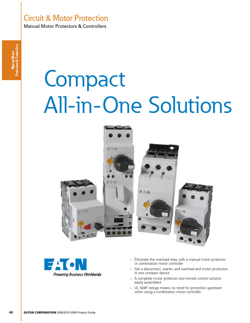
40Circuit & Motor ProtectionManual Motor Protectors & ControllersEATON CORPORATION 2009/2010 OEM Product GuidesEliminate the overload relay with a manual motor protector or combination motor controllersGet a disconnect, starter, and overload and motor protection in one compact devicesA complete motor protector and remote control solution easily assembledsUL 508F ratings means no need for protection upstream when using a combination motor controllerCompactAll-in-One Solutions41Circuit & Motor ProtectionManual Motor Protectors & ControllersPRODUCT OVERVIEWEATON CORPORATION 2009/2010 OEM Product GuideManual Motor Protectors & Controllers Product OverviewXTPR RotaryXTSC Manual Motor ControllerXTFC Combination Motor ControllerPage Page 42Page 42Page 49Page 49Operator Style PushbuttonRotaryRotaryRotaryComponentsManual Motor ProtectorManual Motor ProtectorManual Motor Protector Contactor Connector Kit Manual Motor Protector Contactor Connector Kit Line Side Adapter UL 508 Type E —Yes, Line Side Adapter ——UL 508 Type F ———Yes, Line Side Adapter Branch Motor Circuit FunctionsDisconnectController (manual)Short Circuit Protection Motor Overload Protection DisconnectController (manual)Short Circuit Protection Motor Overload Protection DisconnectController (manual & remote)Short Circuit Protection Motor Overload Protection DisconnectController (manual & remote)Short Circuit Protection Motor Overload Protection FLA Range0.1 – 25A0.1 – 65A0.1 – 65A0.1 – 65AM a n u a l M o t o r P r o t e c t o r s & C o n t r o l l e For our complete product offering, see the Control Products Catalog (CA08102001E).Circuit & Motor ProtectionManual Motor Protectors & ControllersCATALOG SELECTIONEATON CORPORATION 2009/2010 OEM Product Guide XT IEC Manual Motor Protectors — Catalog Numbering System016 = 16A 025 = 25A 032 = 32A 040 = 40A050 = 50A058 = 58A 063 = 63A For our complete product offering, see the Control Products Catalog (CA08102001E).43Circuit & Motor ProtectionManual Motor Protectors & ControllersPRODUCT SELECTIONEATON CORPORATION 2009/2010 OEM Product GuideXTPB Pushbutton Manual Motor Protectors — Global and North American Ratings Motor Protective Device with Thermal and Magnetic Trip0.160.250.40.630.1 – 0.160.16 – 0.250.25 – 0.40.4 – 0.63 2.23.55.68.8——0.060.09—0.060.090.12—0.060.120.18—0.060.120.250.060.120.180.25ባባባባባባባባባባባባባባባባX TPBP16BC1X TPBP25BC1X TPBP40BC1X TPBP63BC111.62.540.63 – 11 – 1.61.6 – 2.52.5 – 4142235560.120.250.370.750.250.550.751.50.250.551.11.50.370.751.12.20.551.11.53ባባ1/21ባባ1/211/23/4121/211-1/23X TPB001BC1X TPB1P6BC1X TPB2P5BC1X TPB004BC16.31012 4 – 6.36.3 – 108 – 1288140168 1.1 2.2 3 2.2 4 5.5 3 4 5.5 3 4 5.5 4 7.5 111-1/2331-1/23337-1/27-1/251010X TPB6P3BC1X TPB010BC1X TPB012BC116202510 – 1616 – 2020 – 2522428035045.55.57.5912.591112.5912.51512.51522355557-1/2101015101520X TPB016BC1X TPB020BC1X TPB025BC1ቢ Select manual motor protectors by full load amperes. Maximum motor ratings (kW, hp) are for reference only.ባ In this range, calculate motor rating according to rated current. Specified values to NEC 430.6(A)(1).ote: N Service Factor (SF) — Setting I r of current scale in dependence of load factor:SF = 1.15 -> I r = 1 x I n mot SF = 1 -> I r = 0.9 x I n motXT IEC Manual Motor Protectorss ON / OFF rotary handle with lockout provision s Class 10 overload protection s Motor applications from 0.1A to 63As Built-in heater and magnetic trip elements to protect the motor s Adjustment dial for setting motor FLAsXTPR Rotary MMP with a lineside adapter is rated for UL 508 Type EM a n u a l M o t o r P r o t e c t o r s & C o n t r o l l e r sFor our complete product offering, see the Control Products Catalog (CA08102001E).Circuit & Motor ProtectionManual Motor Protectors & ControllersPRODUCT SELECTIONEATON CORPORATION 2009/2010 OEM Product Guide XT IEC Manual Motor ProtectorsXTPR Rotary Manual Motor Protectors with Screw Terminals — Global Ratings and North American Ratings Motor Protective Device with Thermal and Magnetic TripFrame B0.160.250.40.630.1 – 0.160.16 – 0.250.25 – 0.40.4 – 0.63 2.23.55.68.8——0.060.09—0.060.090.12—0.060.120.18—0.060.120.250.060.120.180.25ባባባባባባባባባባባባባባባባXTPRP16BC1XTPRP25BC1XTPRP40BC1XTPRP63BC111.62.540.63 – 11 – 1.61.6 – 2.52.5 – 4142235560.120.250.370.750.250.550.751.50.250.551.11.50.370.751.12.20.551.11.53ባ ባ1/21ባ ባ1/211/23/4121/211-1/23XTPR001BC1XTPR1P6BC1XTPR2P5BC1XTPR004BC16.3101216 4 – 6.36.3 – 108 – 1210 – 1688140168224 1.12.234 2.245.57.5345.59345.5947.511 12.51-1/23331-1/233537-1/27-1/2105101010XTPR6P3BC1XTPR010BC1XTPR012BC1XTPR016BC120253216 – 2020 – 2525 – 322803504485.55.57.5912.5151112.51512.51522152230557-1/257-1/210101525152030XTPR020BC1XTPR025BC1XTPR032BC1Frame D1625324010 – 1616 – 2525 – 3232 – 4022435044856045.57.5117.512.51520912.517.522915222412.522223037-1/2101057-1/210151020253015253040XTPR016DC1XTPR025DC1XTPR032DC1XTPR040DC150586540 – 5050 – 5855 – 65700812882141718.525303430373730374545555510——15——3040—40——XTPR050DC1XTPR058DC1XTPR063DC1ቢ Select manual motor protectors by full load amperes. Maximum motor ratings (kW, hp) are for reference only.ባ In this range, calculate motor rating according to rated current. Specified values to NEC 430.6(A)(1).ቤ Catalog number shown comes with screw terminals. For Frame B devices up to 16A, spring cage terminals are available.For spring cage terminals on line and load sides, insert a “C” into the catalog number in the 5th position — Example: XTPR C _BC1.For spring cage terminals on the load side only, insert an “SC” into the catalog number in the 5th and 6th positions — Example: XTPR SC _BC1.ote:N Service Factor (SF) — Setting I r of current scale in dependence of load factor:SF = 1.15 -> I r = 1 x I n mot SF = 1 -> I r = 0.9 x I n motFor our complete product offering, see the Control Products Catalog (CA08102001E).Circuit & Motor ProtectionManual Motor Protectors & ControllersPRODUCT SELECTIONEATON CORPORATION 2009/2010 OEM Product GuideXT IEC Manual Motor ProtectorsXTPR Manual Self-Protected Motor Starters — North American Ratings, UL 508 Type E ቢMotor Protective Device with Thermal and Magnetic Trip0.160.250.40.630.1 – 0.160.16 – 0.250.25 – 0.40.4 – 0.63 2.23.45.68.8ቤቤቤቤቤቤቤቤ1/21/21/21/21/21/21/21/2505050505050505050505050XTPAXLSA XTPAXLSA XTPAXLSA XTPAXLSA XTPRP16BC1XTPRP25BC1XTPRP40BC1XTPRP63BC111.62.540.63 – 11 – 1.61.6 – 2.52.5 – 414223556ቤቤ1/23/4ቤቤ1/211/23/4121/23/41-1/23505050505050505050505050XTPAXLSA XTPAXLSA XTPAXLSA XTPAXLSA XTPR001BC1XTPR1P6BC1XTPR2P5BC1XTPR004BC16.3101216 4 – 6.36.3 – 118 – 1210 – 168814016822413331-1/233537-1/27-1/210510——50504242505042425050——XTPAXLSA XTPAXLSA XTPAXLSA XTPAXLSA XTPR6P3BC1XTPR010BC1XTPR012BC1XTPR016BC120253216 – 2020 – 2525 – 32280350448557-1/257-1/210—1525———421818421818———XTPAXLSA XTPAXLSA XTPAXLSAXTPR020BC1XTPR025BC1XTPR032BC1Frame D1625324010 – 1616 – 2525 – 3232 – 4022435044856037-1/2101057-1/210101020253010253040505050505050505050505050XTPAXLSAD XTPAXLSAD XTPAXLSAD XTPAXLSAD XTPR016DC1XTPR025DC1XTPR032DC1XTPR040DC150586540 – 5050 – 5855 – 65700812882101515151515304040———656565656565———XTPAXLSAD XTPAXLSAD XTPAXLSADXTPR050DC1XTPR058DC1XTPR063DC1ቢ UL 508 Type E starters are assembled from a standard XTPR and a special incoming terminal line side adapter (XTPAXLSA or XTPAXLSAD). ባ Select manual motor protectors by full load amperes. Maximum motor ratings (kW, hp) are for reference only. ቤ In this range, calculate motor rating according to rated current. Specified values to NEC 430.6(A)(1).ote:N A UL 508 Type E self-protected manual combination starter (XTPR) consists of a manual motor protector (XTPR) and a UL listed line side adapter (e.g., XTPAXLSA). The Type E self-protectedmanual combination starter alone is a legitimate short-circuit protective device and disconnect means for the downstream motor, while the contactor has been added to provide remote operation of the motor circuit.For our complete product offering, see the Control Products Catalog (CA08102001E).46Circuit & Motor ProtectionManual Motor Protectors & ControllersPRODUCT SELECTIONEATON CORPORATION 2009/2010 OEM Product Guide XT IEC Manual Motor Protectors — AccessoriesAuxiliary ContactsIP65 Rotary Handle MechanismቢባቤDescriptionPkg. Qty.Catalog NumberComplete Kits — Includes Handle, Shaft and Required HardwareRotary Handle Mechanism IP65 Black — For use on main switches to IEC / EN 60204.1X TPAXRHMB Rotary Handle Mechanism IP65 Red / Yellow — For use on main switch with Emergency-Stop function to IEC / EN 60204.1X TPAXRHMRY Rotary Handle Mechanism IP65 Black — For use on main switches to IEC / EN 60204 where XTPR is mounted 90° from vertical.1 X TPAXRHM90B Rotary Handle Mechanism IP65 Red / Yellow — For use on main switch with Emergency-Stop function to IEC / EN 60204 where XTPR is mounted 90° from vertical.1X TPAXRHM90RYቢ With ON/OFF switch position and “+” (tripped), lockable with 3 padlocks, 4 – 8 mm hasp. Can be locked in the OFF position, if required.ባ Rotary handle mechanisms ship with door interlock disabled. See instruction publication with product for how to enable door interlock.ቤ Not for use with XTPAXFAEM20 early-make front-mount auxiliary contact.Shunt ReleaseCatalog Number — Screw Terminals Pkg. Qty.X TPAXSR120V60H X TPAXSR240V60H X TPAXSR480V60H X TPAXSR24VDC2222Undervoltage ReleaseCatalog Number — Screw Terminals Pkg. Qty.X TPAXUVR120V60H X TPAXUVR240V60H X TPAXUVR480V60H222For our complete product offering, see the Control Products Catalog (CA08102001E).47Circuit & Motor ProtectionManual Motor Protectors & ControllersPRODUCT SELECTIONEATON CORPORATION 2009/2010 OEM Product GuideXT IEC Manual Motor Protectors — Accessories Three-Phase Commoning Links ቢቢ Protected against accidental contact. B-Frame short circuit proof Ue = 690V, Iu = 63A; D-Frame short circuit proof Ue = 690V, Iu = 128A. Frame B links can be combined by rotating mounting.Frame D links cannot be combined.Incoming Terminal for Three-Phase Commoning Link ቢFor Use with...Pkg Qty.Catalog Number B-Frame XTPR, XTPB5X TPAXITቢ For three-phase commoning link, protected against accidental contact, Ue = 690V, Iu = 63A;for conductor cross-sections: 2.5 – 25 mm 2 stranded; 2.5 – 16 mm 2 flexible with ferrules, AWG 14-6.Line-Side Adapter ቢFor Use with...Pkg Qty.Catalog Number B-Frame XTPR to Create a UL 508 Type E/F Manual Combination Starter5X TPAXLSAD-Frame XTPR to Create a UL 508 Type E/F Manual Combination Starter1X TPAXLSAD ባቢ XTPAXLSA is for three-phase commoning link, finger- and back-of-hand proof, Ue = 690V,Iu = 60A; for conductor cross sections: 2.5 – 25 mm 2 stranded, 2.5 – 16 mm 2 flexible with ferrule, AWG 14-6.ባ XTPAXLSAD cannot be combined with three-phase commoning links.For our complete product offering, see the Control Products Catalog (CA08102001E).M a P r o t e c t o rCircuit & Motor ProtectionManual Motor Protectors & ControllersPRODUCT SELECTIONEATON CORPORATION 2009/2010 OEM Product Guide XT IEC Manual Motor Protectors — AccessoriesNon-Reversing StartersXTPB Pushbutton Manual Motor Protectors — North American Usage ቢባIP65NEMA3R, 4X, 12, 13XTPB MMP Only or with: XTPAXFA..., XTPBXFAEM20, XTPAXSA..., XTPAXUVR..., XTPAXSR..., XTPAXCLWith actuating diaphragmXTPBXENAS65IP65NEMA3R, 4X, 12, 13XTPB MMP Only or with: XTPAXFA...,XTPBXFAEM20, XTPAXUVR..., XTPAXSR..., XTPAXCL With Emergency-Stop (E-Stop)pushbutton actuator, Red-YellowXTPBXENASES65B-Frame (0.1 – 32A) XTPR Rotary Manual Motor Protectors — North American Usage ቤIP55NEMA 1, 12, 3RB-Frame XTPR Only or with: XTPAXSA...and XTPAXFA..., XTPAXUVR...and XTPAXFA..., XTPAXSR...and XTPAXFA..., XTPAXCLWith red/yellow rotary handle for use as Emergency-Stop switch to VDE 0113XTPAXENAS55RY D-Frame (10 – 65A) XTPR Rotary Manual Motor Protectors ብቦIP65NEMA 1, 12, 3R, 4XD-Frame XTPR Only or with: XTPAXFA..., XTPAXFAEM20, XTPAXSA..., XTPAXSATR..., XTPAXUVR..., XTPAXSR..., XTPAXCLWith red/yellow rotary handle for use as Emergency-Stop switches to IEC / EN 60204XTPAXENCSD65RYቢ Built-in terminal for PE(N).ባ North American enclosures come with conduit adapters for use with 1/2” NPT.ቤ Built-in N and PE terminal, lower part without knockouts.ብ Integrated terminal for PE(N) connection.ቦ % Metric knockouts:Top ÷ bottom: M25/M32 In backplate: M25/M32 Control cable entry: M20For our complete product offering, see the Control Products Catalog (CA08102001E).。
西门子 SIRIUS 软起动器 3RW44 系统说明书

软起动器 3RW44系统操作手册2006年2月出版安全说明为了保证您的人身安全、防止出现财产损失,您必须遵守本手册中的有关提示。
有关您的人身安全的提示均有醒目的三角形警告标志,仅和财产损失有关的提示没有三角形警告标志。
根据危险等级,以降序形式将警告提示表述如下:危险表示如果不采取相应的防范措施,将会出现死亡、或者重伤的危险。
警告表示如果不采取相应的防范措施,将有可能出现死亡、或者重伤的危险。
小心带有三角形警告标志,则表示如果不采取相应的防范措施,将可能出现轻伤危险。
小心不带三角形警告标志,则表示如果不采取相应的防范措施,将有可能出现财产损失的危险。
注意表示如果不遵守相应的提示,可能出现意外结果或者情况。
当同时有多种危险等级出现时,所使用的始终是最高等级的警告提示。
如果在某一个警告提示中使用三角形警报标志来警告人身伤害的危险,则有可能也会在同一提示中附带有财产损失警告。
训练有素的专业人员相关设备 / 系统仅允许在使用本手册的情况下安装和使用。
只能由训练有素的专业人员调试和操作设备 / 系统。
本手册安全说明中所述之训练有素的人员是指有资格根据安全技术的标准,对设备、系统和电路进行操作、接地和标识的人员。
按照规定使用请注意以下事项:警告该设备只能用在产品目录和技术说明中所规定的使用情况下,且只能与西门子所推荐或者认可的外购设备和外购部件配合使用。
正确地进行运输、仓储、安装和装配以及谨慎操作和维护,是产品无故障可靠运行的前提条件。
商标带有注册标记 ® 的所有名称标志均为西门子股份公司的注册商标。
本手册中的其它名称标志如果被第三方用于其自身的目的,就有可能损害所有人的权益。
西门子股份公司版权 2004。
保留所有权利。
未经明确许可,不得转让和复制本资料,也不得利用本资料的内容和将其透露给他人。
如有违背,必追究赔偿责任。
保留所有权利,特别是申请专利或者登记使用新型专利的权利。
免责条款我们已经对本手册与所描述之硬件和软件的一致性进行过检查。
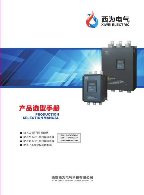
西为电气KSR系列软起动器产品选型手册2017.3.2
W4×6d1×6D1D4D2DW3W2W1H1H2图F-2d ×4H1H2W3W2W1W4×6D1D2D4D 图F -1d ×4d 1×6SSKSR100-008-3~KSR100-030-3KSR100-037-3~KSR100-090-3KSR100-110-3~KSR100-200-3KSR100-250-3~KSR100-400-318018027430429029043549219619620521116516523027022422438043095951281431251253951ΦΦ5.5Φ9Φ95.553537887.5152030403355ΦΦ8Φ10.5Φ116 6.5 72229图F-1图F-2/KSR201型软起动器已内置旁路接触器。
可编程起动;运行;旁路;故障;软停可编程选择可编程KSR201型90KW 及以上软起动增加L 、N 接线端子,需要外接AC220V 电源。
★图F -3壁挂式图F-3KSR201-037-3KSR201-008-3~18033521215031376123Φ75315320Φ612KSR201-075-3KSR201-055-3~210393255150362114117Φ753203653Φ818KSR201-187-3KSR201-090-3~2605442372204276Φ983355128Φ1122KSR201-045-320148Φ13KSR201-280-3KSR201-200-3~3 KSR201型软起动器已内置旁路接触器。
2322995982595286Φ826413Φ9KSR201-500-3KSR201-450-3~43581736080106687d1×24d 4×H1H2W3W46×W2W13535H3图F-4壁挂式图F-4KSR201-400-3KSR201-320-3~48474536Φ11131607226003液晶显示软起动器3300表示300型,301表示301型液晶显示型号命名规则液晶显示注:KSR300/301系列液晶显示软起动器的接线、外形及安装尺寸与KSR200/201 系列相同. 请参考【02--KSR200/201系列数字式软起动器】KSR301型 软起动器 已内置旁 路接触器/330适用电压等级适配电机功率产品设计序号产品命名04数字式软起动柜地址:西安市高新区西部大道170号丰泽科技园2号楼81123922传真:029-********网址:邮箱:**************400-9626-100免费热线:。
易达特S8x1软启动器参数化操作指南说明书

SoftstarterS8x1 ChangeSwitching from S801+ to S811+ Parameterization via KeypadContent1 General (5)2 Exchange of the devices (5)2.1 Functions (5)2.2 Terminal assignment (6)3 Connection example (8)3.1 S811+ (8)3.2 S801+ (9)4 S811+ configuration (9)4.1 DIP switch on keypad (9)4.1.1 Overload Trip Class (10)4.1.2 Soft Stop Time (10)4.1.3 Motor Nameplate FLA (10)4.1.4 Phase Reversal Fault (11)4.1.5 Kick Start Time (11)4.1.6 Initial Torque (11)4.1.7 Stall Fault (12)4.1.8 Reset Mode (12)4.1.9 Jam Fault (12)4.1.10 Kick Start Torque (13)4.1.11 Phase Loss Fault (13)4.1.12 Overload Fault (13)4.1.13 Soft Start Time (14)4.2 Parameter at S811+ (14)4.2.1 Display menu (monitoring) (14)4.2.2 Menu: Soft start configuration (15)4.2.3 Menu: Privacy settings (15)5 Documentation (15)Danger! - Dangerous electrical voltage!∙Disconnect the power supply of the device.∙Ensure that devices cannot be accidentally restarted.∙Verify isolation from the supply.∙Cover or enclose any adjacent live components.∙Follow the engineering instructions (AWA/IL) for the device concerned.∙Only suitably qualified personnel in accordance with EN 50110-1/-2 (VDE 0105 Part 100) may work on this device/system.∙Before installation and before touching the device ensure that you are free of electrostatic charge.∙The functional earth (FE, PES) must be connected to the protective earth (PE) or the potential equalization.Thesystem installer is responsible for implementing this connection.∙Connecting cables and signal lines should be installed so that inductive or capacitive interference does not impair the automatic control functions.∙Suitable safety hardware and software measures should be implemented for the I/O interface so that an open circuit on the signal side does not result in undefined states.∙Deviations of the mains voltage from the rated value must not exceed the tolerance limits given in the specification, otherwise this may cause malfunction and/or dangerous operation.∙Emergency stop devices complying with IEC/EN 60204-1 must be effective in all operating modes. Unlatch-ing of the emergency-stop devices must not cause a restart.∙Devices that are designed for mounting in housings or control cabinets must only be operated and con-trolled after they have been properly installed and with the housing closed.∙Wherever faults may cause injury or material damage, external measures must be implemented to ensurea safe operating state in the event of a fault or malfunction (e.g. by means of separate limit switches, me-chanical interlocks etc.).∙Softstarter may have hot surfaces during and immediately after operation.∙Removal of the required covers, improper installation or incorrect operation of motor or Softstarter may destroy the device and may lead to serious injury or damage.∙The applicable national safety regulations and accident prevention recommendations must be applied to all work carried on live Softstarter.∙The electrical installation must be carried out in accordance with the relevant electrical regulations (e. g.with regard to cable cross sections, fuses, PE).∙Transport, installation, commissioning and maintenance work must be carried out only by qualified per-sonnel (IEC 60364, HD 384 and national occupational safety regulations).∙Installations containing Softstarter must be provided with additional monitoring and protective devices in accordance with the applicable safety regulations. Modifications to the Softstarter using the operating software are permitted.∙All covers and doors must be kept closed during operation.∙To reduce the hazards for people or equipment, the user must include in the machine design measures that restrict the consequences of a malfunction or failure of the Softstarter (increased motor speed or sudden standstill of motor). These measures include: – Other independent devices for monitoring safety related variables (speed, travel, end positions etc.).–Electrical or non-electrical system-wide measures (electrical or mechanical interlocks).– Never touch live parts or cable connections of the Softstarter after it has been disconnected from the power supply. Due to the charge in the capacitors, these parts may still be alive after disconnection. Con-sider appropriate warning signs.DisclaimerThe information, recommendations, descriptions, and safety notations in this document are based on Eaton’s experience and judgment and may not cover all contingencies. If further information is required, an Eaton sales office should be consulted. Sale of the product shown in this literature is subject to the terms and conditions outlined in the applicable Terms and Conditions for Sale of Eaton or other contractual agreement between Eaton and the purchaser. THERE ARE NO UNDERSTAND-INGS, AGREEMENTS, WARRANTIES, EXPRESSED OR IMPLIED, INCLUDING WARRANTIES OF FITNESS FOR A PARTICULAR PURPOSE OR MERCHANTABILITY, OTHER THAN THOSE SPECIFICALLY SET OUT IN ANY EXISTING CONTRACT BETWEEN THE PARTIES. ANY SUCH CONTRACT STATES THE ENTIRE OBLI-GATION OF EATON. THE CONTENTS OF THIS DOCUMENT SHALL NOT BECOME PART OF OR MODIFY ANY CONTRACT BETWEEN THE PARTIES. As far as applicable mandatory law allows so, in no event will Eaton be responsible to the purchaser or user in contract, in tort (including negligence), strict liability, or otherwise for any special, indirect, incidental, or consequential damage or loss whatsoev-er, including but not limited to damage or loss of use of equipment, plant or power system, cost of capital, loss of power, additional expenses in the use of existing power facilities, or claims against the purchaser or user by its customers resulting from the use of the information, recommendations, and descriptions contained herein. The information contained in this manual is subject to change without notice.1GeneralThe following information describes a change from the softstarter series S801+ to the seriesS811+.In the following, the differences to be observed in terms of plant extension or new project planning with S811+ as well as the replacement of devices of the S801+ series are shown.2Exchange of the devicesThe devices differ mainly in the following points:2.1Functionsmunication2.Pump algorithm3.Display4.Programmable clamps5.Safety function2.2Terminal assignmentHere is a simple difference:- The terminals of the S811+ are configurable- the terminals assignment for the S801+ are not configurableThe S811+ has the same input configuration as the S801+, except for terminal 3. The terminal assignment for S801+ and S811+ looks like:S811+The following configuration options are available (digital input and relays):S801+3Connection example 3.1S811+3.2S801+4S811+ configuration 4.1DIP switch on keypad4.1.1Overload Trip Class4.1.2Soft Stop Time4.1.3Motor Nameplate FLA4.1.4Phase Reversal Fault4.1.5Kick Start Time4.1.6Initial Torque4.1.7Stall Fault4.1.8Reset Mode4.1.9Jam Fault4.1.10Kick Start Torque4.1.11Phase Loss Fault4.1.12Overload Fault4.1.13Soft Start Time4.2Parameter at S811+4.2.1Display menu (monitoring)∙Fault/Warning (actual fault)∙Fault/Warning list∙Fault/Warning history∙ 3 Ø current∙Current in % (motor rated current) ∙DC control voltage∙ 3 Ø voltage∙Frequency∙Phase sequence∙Average phase power∙Power factor∙Temperature memory∙Pol temperature∙Start counter∙Auto reset counter∙…. Have a look in the manual4.2.2Menu: Soft start configuration∙Motor nameplate FLA∙Overload trip class∙Phasenreihenfolge∙Start Methode∙Soft start time∙Kick start torque∙Kick start time∙Reset mode∙Auto reset delay∙Auto reset limit∙Motor connection configuration 4.2.3Menu: Privacy settings∙Overload fault active∙Overload at start∙Motor rated voltage∙Enable undervoltage shutdown∙Switching point undervoltage∙Delay undervoltage cutoff∙Enable overvoltage shutdown∙Switching point overvoltage∙Delay shutdown overvoltage5Documentation。
S811软启动器安装说明书
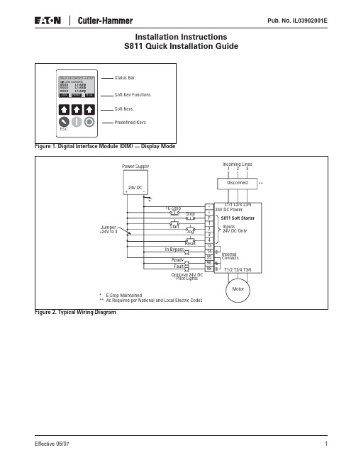
Pub. No. IL03902001EInstallation InstructionsS811 Quick Installation GuideEffective 06/071Pub. No. IL03902001EEffective 06/072Table 1. Settings for Typical Applicationsᕄ A value of 1 (Current Limit Start) may be selected for this application but longer starting times and constant loads should be observed when starting. ᕅ Customers operating equipment on either ungrounded systems or high resistance grounded systems may need to adjust the severity and/or duration of imbalance protection. These power systems periodically experience phase angle shifts that can be picked up as a false imbalance trip. ᕆ2 second stop time must be set if this is an ammonia compressor application.Pub. No. IL03902001EEffective 06/073FLA Setting CalculationThe FLA setting is a function of the product of the motor nameplate full load amperes (FLA) and a multiplier from the service factor multiplier (SF) in the Table 2 below.FLA Setting = Motor FLA x SF MultiplierFor example, an S811R13N3S with a 100 amp, 1.15 service factor motor should have an FLA setting of 115 (100 x 1.15).Please refer to sizing charts in product user manual, MN03902002E, or call 877-ETN CARE (386-2273) forassistance in sizing a soft starter for specific applications. Table 2. FLA Rangesᕇ500A rating does not have IEC certification.Wiring and Control Check List for Operating through the Control Terminal Block❏ A jumper is installed between terminals P and 1 for two-wire control (e.g. RUN/STOP toggle switch or PLC control)❏24V power supply meets minimum requirements (55 watt steady state, 240 watt inrush for 180 mS, 30V DC max.)❏Control power wire for the positive and negative ter-minals is 14 AWG or larger ❏Control wire length less than 100 feet❏24V is supplied to pin 3 on the control terminal block if controlling through these terminals is desiredPower Wiring Check List❏ 24V DC control voltage will be applied to terminal P ❏ Phase sequence is correct (ABC), otherwise soft starter will trip on phase reversal ❏ If output isolation contactor is used, it cannot open until the soft starter stops to prevent a low current trip After completing the above, apply line power; apply 24V DC control voltage, and then initiate start signal to energize motor.Check List — Settings — Special Applications❏ You may improve performance if operating on genera-tor power by setting the kick start time to 2 seconds and kick start torque to half the value of the initialtorque setting. This creates a step loading effect of the generator, allowing the governor to regulate the power demand of starting larger motors.TroubleshootingFor additional setting details refer to the S811 User Manual (# MN03902002E) available at /electrical. For technical questions, please contact EatonCare at 877-ETN CARE (386-2273).Frame Size Catalog Number FLA Current Range N65 mm S811N37N3S 11 – 37 S811N66N3S 20 – 66R110 mm S811R10N3S 32 – 105 S811R13N3S42 – 135T200 mmS811T18N3S, S811T18V3S 56 – 180 S811T24N3S, S811T24V3S 75 – 240 S811T30N3S, S811T30V3S95 – 304U200 mmS811U36N3S 112 – 360 S811U42N3S 131 – 420 S811U50N3S156 – 500 ᕇ V290 mmS811V36N3S, S811V36V3S 112 – 360 S811V42N3S, S811V42V3S 131 – 420 S811V50N3S, S811V50V3S 156 – 500 S811V65N3S, S811V65V3S 203 – 650 S811V72N3S, S811V72V3S 225 – 720 S811V85N3S, S811V85V3S 265 – 850 S811V10N3S310 – 1000Pub. No. IL03902001EEaton CorporationElectrical Group1000 Cherrington ParkwayMoon Township, PA 15108United States877-ETN CARE (877-386-2273)© 2007 Eaton CorporationAll Rights ReservedPrinted in USAPublication No. IL03902001E/CPGJune 2007。
电动机软启动器一用一备控制电路工作原理

电动机软启动器一用一备控制电路工作原理本电路是一台电动机用一个软启动器,当出现故障时,再启动另一台备用电动机,待故障电动机排除故障后再恢复使用原电机。
电路如下图所示,其中的图a、b、c分别为主电路、控制电路和软启动控制端子。
工作原理:当按下启动按钮SB1,中间继电器IKA1线圈得电吸合,且其常开辅助触点1KAI-I闭合自锁,其常闭触点1KAl-2断开,停止指示灯1HLR熄灭,触点1KAl-4闭合,软启动器启动工作,电动机Ml启动运转。
当电动机Ml转速近于(或达到)额定转速时,旁路继电器JC1得电吸合,触点JCH闭合,运行指示IHLC点亮,旁路交流接触器KMI线圈得电吸合,主触点KMl-2闭合,将软启动器主电路(晶闸管)短接,进入旁路运行。
当需停机时,按下停止按钮SB2,中间继电器1KA1断电释放,触点1KAl-4断开复位,软启动器停止工作;旁路继电器JC1失电释放,触点JCl-I复位断开,接触器KM1失电释放,主触点KW-2断开复位,电动机Ml停止运行。
当电动机Ml在运行过程中,发生过电流、断相、堵转等故障时,故障继电器AR1吸合,电触点ARI-2闭合,时间继电器KT2线圈得电吸合,得电延时闭合触点KT2-I闭合,中间继电器2KA1线圈得电吸合且自锁,触点2KA1闭合,电动机M2软启动运行。
当转速达到额定转速时,旁路继电器JC2吸合动作,触点JC2闭合,旁路交流接触器KM2线圈得电吸合,主触点KM2-2闭合,电动机M2进入旁路运行状态。
而此时故障触点ARl-I复位断开,切断中间继电器1KAI线圈回路电源且失电释放,其触点1KAl-4复位断开,软启动器STR1停止工作,旁路继电器JC1失电释放,触点JCl-I断开旁路接触器KM1线圈电源且失电释放,主触点KMl-2复位断开,电动机Ml因故障停机,待机排除故障。
当需停止电动机M2时,按下停止按钮SB4即可。
本电路的特点是一台电动机Ml发生故障时,通过故障继电器吸合动作,时间继电器的吸合触点延时转换为另一台电动机M2运行。
一拖六电机软启动介绍

技术方案
株洲变流技术国家工程研究中心
二 OO 七年十一月.......................................................................................................................... 3 1.1、概述................................................................................................................................... 3 1.2、软起动的分类 ................................................................................................................... 3 1.3、TGQ 软起动特色................................................................................................................4
1.2、软起动的分类
软起动可分为有级和无级两类,有级的如星/角变换软起动、自耦变压器软起动、 电抗器软起动等,都避免不了二次冲击。无级的有液阻软起动、磁控软起动和晶闸管 软起动。以技术性能比较,晶闸管方式的智能型软起动已逐渐占据主导地位,因而国
3
内低压软起动(380V、660V、1140V 等)市场主要是采用晶闸管方式的软起动器。在 中高压应用中,国外产品基本都是晶闸管方式的软起动器。而国内由于技术方面的原 因,有多种软起动方式并存,但逐渐将向智能型的、应用高压晶闸管方式的软起动器 转化。
伊顿电子产品参考手册说明书

提供动力。
探索今天的伊顿。
我们提供:• 方案• • •动及动力总成解决方案马达控制设备命令和控制设备终端保护产品自动化和驱动产品134MOEM 市场综合样本目录2马达和线路控制设备伊顿拥有超过百年的接触器研发和制造经验,为用户提供至3185A 的线路控制解决方案,并提供不同系列的产品以满足用户的的多种要求Xstart 系列接触器:全球化的产品,提供包括UL 在内的主流认证,最高达3185安培(AC-1)的产品:• 独特的CT 型励磁机构,功耗更小;• 115A 以上集成电子线路板,降低功耗同时工作电压幅度更宽;• 580A 以上真空灭弧,应对严苛使用环境,业界最长预期寿命;• 提供本地化的XstartC 系列(认证情况请咨询当地销售办事处)。
D 系列接触器:本地化的产品,提供最高到500A 的高效控制和保护方案,应用于泵、风机、压缩机等场合,提供功能全面的辅助触点和宽幅的控制线圈电压选项。
• 齐全的线圈控制电压,185A 以上更提供交直流通用产品;• 全系列内置辅助触点• 百万次以上电气寿命• 使用温度-20 °C ~ +55 °CE 系列接触器:全球最小的电磁接触器之一,有效地利用空间,可靠性增强,材料使用更高效。
E 系列接触器额定值可至AC-3, 95A@400V ,最高工作电压高达660V ,体积小巧,却提供强大的性能。
• 百万次以上电气寿命• 690V 绝缘额定值• 最多可加装6个辅助触点模块• 常用交流控制电压及直流24VDC 线圈1马达控制设备目录电机控制产品 xStart C 接触器式继电器DILA..C 接触器DILM..C 过载继电器ZB..C电动机保护断路器PKZMC 电机控制产品 D 系列接触器 XTCD 热过载继电器 XTOD 电气行业解决方案 Eline 控制继电器 XTRG 接触器 XTCG热过载继电器 XTOD/XTOG电机控制产品 xStart C电机控制产品 D 系列电气行业解决方案Eline1接触器式继电器DILA..C目录系统概览 . . . . . . . . . . . . . . . . . . . . . . . . . . . . . . . . . . . . . . . . . . . . . . . . . . . . . . . . . . . . . . . . . . . . .本体DILA..C . . . . . . . . . . . . . . . . . . . . . . . . . . . . . . . . . . . . . . . . . . . . . . . . . . . . . . . . . . . . . . . . . .辅助触点模块 . . . . . . . . . . . . . . . . . . . . . . . . . . . . . . . . . . . . . . . . . . . . . . . . . . . . . . . . . . . . . . . .附件 . . . . . . . . . . . . . . . . . . . . . . . . . . . . . . . . . . . . . . . . . . . . . . . . . . . . . . . . . . . . . . . . . . . . . . . . .操作电压 . . . . . . . . . . . . . . . . . . . . . . . . . . . . . . . . . . . . . . . . . . . . . . . . . . . . . . . . . . . . . . . . . . . . .特性曲线,触点行程图 . . . . . . . . . . . . . . . . . . . . . . . . . . . . . . . . . . . . . . . . . . . . . . . . . . . . . . . .技术数据 . . . . . . . . . . . . . . . . . . . . . . . . . . . . . . . . . . . . . . . . . . . . . . . . . . . . . . . . . . . . . . . . . . . . .尺寸 . . . . . . . . . . . . . . . . . . . . . . . . . . . . . . . . . . . . . . . . . . . . . . . . . . . . . . . . . . . . . . . . . . . . . . . . .4极触点多种组合约定发热电流(I th )16A 交流与直流操作的产品尺寸相同直流操作的产品内置浪涌抑制器••••接触器式继电器DILA..C35791112131911接触器式继电器DILA..C说明121接触器式继电器DILA..C系统概览31接触器式继电器DILA..C系统概览4系统概览本体AC 或DC 操作电磁系统AC DC 可以扩展到8对触点反向互锁触点模块化系统螺钉连接和卡装手指接触防护螺钉端子第5页起抑制电路用于直流操作接触器式继电器的保护电路(所有直流型均内置)用于交流操作接触器式继电器的保护电路第32页起辅助触点模块23, 42或4极反向互锁触点第7页起124 – 400V, 50, 60, 50/60 Hz0.8 – 1.1 × U c 24 VA/3.4 VA 24 – 220 V DC0.8 – 1.1 × U c 于24 V :0.7 – 1.3 × U c 无附加辅助触点模块环境温度+40°C 3W/3W1接触器式继电器DILA..C本体5接线方式:螺钉端子触点N/O = 常开N/C = 常闭带反向互锁触点的本体额定工作电流AC – 15220 V230 V240 VI e约定发热电流,敞开,于60°CI th代码序号触点序号380 V400 V415 VI e1本体DILAC-XHI(V)...DILAC-XHI(V)...DILAC-XHI(V)...DILA-40C(220-230V50Hz)114842DILA-31C(220-230V50Hz)114852DILA-22C(220-230V50Hz)114862DILA-40C(24VDC)114847DILA-31C(24VDC)114857DILA-22C(24VDC)1148671件1件1件可以组合辅助触点模块标准包装说明AC 操作型号订货号操作电压220-230V50HzDC 操作型号订货号操作电压24VDC附件1 抑制器2 辅助触点模块操作电压页数32711触点编号,符合EN 50011线圈端子标记,符合EN 50005直流操作的接触器式继电器具有一个内置的保护电路。
伊顿集团Power Xpert Release 脱扣器用于Power Defense 塑壳断路器 M

Power Xpert® Release 脱扣器用于Power Defense 塑壳断路器免责条款及责任限制本手册所含之信息、建议、描述及安全符号皆基于伊顿集团(以下称“伊顿”)的经验及判断,无法涵盖所有可能性。
如果需要更多信息,应咨询伊顿销售办事处。
本手册所涉产品之销售,受伊顿相关销售政策或其他伊顿与购买方之间的合同协议中所述之条款及条件的限制。
除了双方现有协议中特别约定之外,本手册没有表示或暗示任何谅解、协议及保证,包括适于特定目的或试销性之保证。
应将合同约定视为所有伊顿承担的责任。
本手册之内容不应构成双方合同的一部分,或旨在修改双方间的任何合同。
在任何情况下,伊顿公司都不对购买者或用户的以下情况担责:包括侵权(包括过失),严格责任或其它任何特殊的,间接的,附带的或造成的破坏或损失,包括但不限于设备,工厂或电力系统使用中损坏或丢失,资本成本,功率损耗,使用现有电力设施的额外费用,客户由于使用本文所包含信息,建议和描述而造成的对购买方或用户的索赔。
本手册所含信息如有变更,恕不另行通知。
Ii 用于Power Defense 塑壳断路器的Power Xpert® Release 脱扣器MN012007EN March 2019 MN012007EN目录1. POWER XPERT® RELEASE 脱扣器简介 . . . . . . . . . . . 11.1 保护装置概述 . . . . . . . . . . . . . . . . . . . . . . . . . . . . . . . .11.2 计量功能 . . . . . . . . . . . . . . . . . . . . . . . . . . . . . . . . . . . .41.3 健康监控 . . . . . . . . . . . . . . . . . . . . . . . . . . . . . . . . . . . 51.4 通信特性 . . . . . . . . . . . . . . . . . . . . . . . . . . . . . . . . . . . .51.5 控制特性. . . . . . . . . . . . . . . . . . . . . . . . . . . . . . . . . . . . 52 PXR用户界面. . . . . . . . . . . . . . . . . . . . . . . . . . . . . . . . . .62.1 关键的界面功能 . . . . . . . . . . . . . . . . . . . . . . . . . . 62.2 PXR 25、PXR 25 马达保护和20D显示屏(带键盘) . .82.3 PXR 20 (带拨码开关) . . . . . . . . . . . . . . . . . . . . . . . . . 92.4 PXR 10 (带简化的拨码开关). . . . . . . . . . . . . . . . . . . . .92.5 PXR 10 马达保护(带简化的拨码开关) . . . . . . . . . . . . . .103 线路保护设置描述. . . . . . . . . . . . . . . . . . . . . . . . . . . . . . . 103.1 长延时设定和时间设置 . . . . . . . . . . . . . . . . . . . . . . . . . .103.2 短延时整定和时间设定 . . . . . . . . . . . . . . . . . . . . . . . . . 113.3 瞬时整定设定 . . . . . . . . . . . . . . . . . . . . . . . . . . . . . . . . .113.4 接地故障设定 . . . . . . . . . . . . . . . . . . . . . . . . . . . . . . . . .113.5 马达保护设置描述 . . . . . . . . . . . . . . . . . . . . . . . . . . . . . 133.6 维护模式保护(ARMS). . . . . . . . . . . . . . . . . . . . . . . . 153.7 高瞬 . . . . . . . . . . . . . . . . . . . . . . . . . . . . . . . . . . . . . . . . 163.8 区域选择联锁(ZSI). . . . . . . . . . . . . . . . . . . . . . . . . . . . . 163.9 工作温度. . . . . . . . . . . . . . . . . . . . . . . . . . . . . . . . . . . . .174 通信功能 . . . . . . . . . . . . . . . . . . . . . . . . . . . . . . . . . . . . . . 174.1 集成的Modbus - 远程终端设备(RTU单元) . . . . . . . . .174.2 USB端口. . . . . . . . . . . . . . . . . . . . . . . . . . . . . . . . . . . . . 184.3 外部通信适配器模块(CAM) . . . . . . . . . . . . . . . . . . . . .185 脱扣器的外部配线 . . . . . . . . . . . . . . . . . . . . . . . . . . . . . . . . 195.1 配线表 . . . . . . . . . . . . . . . . . . . . . . . . . . . . . . . . . . . . . . .195.2 辅助电源 . . . . . . . . . . . . . . . . . . . . . . . . . . . . . . . . . . . . . .195.3 通用继电器点表 . . . . . . . . . . . . . . . . . . . . . . . . . . . . . . . . .205.4 中性电压互感器 . . . . . . . . . . . . . . . . . . . . . . . . . . . . . . . . 216 POWER XPERT® PROTECTION MANAGER - 配置软件. . . 226.1 通过 PXPM 进行设定点配置 . . . . . . . . . . . . . . . . . . . . . . 226.2 远程控制. . . . . . . . . . . . . . . . . . . . . . . . . . . . . . . . . . . . . . 246.3 测试断路器和脱扣器. . . . . . . . . . . . . . . . . . . . . . . . . . . . . . . 256.4 事件记录. . . . . . . . . . . . . . . . . . . . . . . . . . . . . . . . . . . . . 277 事件、报警和跳闸记录以及波形捕获 . . . . . . . . . . . . . . . . . . 287.1 触发原因和数据日志矩阵 . . . . . . . . . . . . . . . . . . . . . . . . . . . .29用于Power Defense 塑壳断路器的Power Xpert® Release 脱扣器MN012007EN March 2019 iiiMN012007EN8 健康监控 . . . . . . . . . . . . . . . . . . . . . . . . . . . . . . . . . . . . . . . . . .308.1 健康监控介绍和功能. . . . . . . . . . . . . . . . . . . . . . . . . . . . . . . 308.2 健康监控参数值. . . . . . . . . . . . . . . . . . . . . . . . . . . . . . . . . . .308.3 健康监控重置步骤. . . . . . . . . . . . . . . . . . . . . . . . . . . . . . . . . 319 脱扣器维护 . . . . . . . . . . . . . . . . . . . . . . . . . . . . . . . . . . . . . . .339.1 更换电池 . . . . . . . . . . . . . . . . . . . . . . . . . . . . . . . . . . . . . . . 339.2 更换电子式脱扣器 . . . . . . . . . . . . . . . . . . . . . . . . . . . . . . . . 3310 可用的保护设置. . . . . . . . . . . . . . . . . . . . . . . . . . . . . . . . . . . .. 3310.1 识别脱扣器 . . . . . . . . . . . . . . . . . . . . . . . . . . . . . . . . . . . .3310.2 详细的设置表 . . . . . . . . . . . . . . . . . . . . . . . . . . . . . . . . . . 3511 MODBUS寄存器映射. . . . . . . . . . . . . . . . . . . . . . . . . . . . . .5011.1 查看/设定Modbus参数 . . . . . . . . . . . . . . . . . . . . . . . . . . . 5011.2 通信协议. . . . . . . . . . . . . . . . . . . . . . . . . . . . . . . . . . . . . . .50iv 用于Power Defense 塑壳断路器的Power Xpert® Release 脱扣器MN012007EN March 2019 1. Power Xpert® Release 脱扣器简介1. Power Xpert® Release 脱扣器简介Power Xpert Release(PXR)脱扣器功能强大,操作灵活,可以针对各种保护应用进行配置。
深圳易盟一特科技有限公司 EM-GS系列电机软启动器说明书

EM-GS系列电机软启动器地址:深圳市宝安区西乡街道办流塘前进二路北区3号六楼电话:*************传真:*************邮编:518101前言感谢您选用本公司的智能化电机软起动器产品,该产品用于三相鼠笼式异步电动机软起、软停控制,在使用前请仔细阅读和理解本说明书中的内容。
在本软起动产品的安装、使用、维护过程中必须注意以下事项:安装前请务必详细阅读本操作说明。
必须由专业技术人员安装本软起动器。
必须让电动机的规格与本软起动器相匹配。
严禁在软起动器输出端(U.V.W) 接电容器。
安装后裸露的接线端子必须用绝缘胶带包好。
软起动器或相关的其他设备应可靠接地。
设备维修时必须切断输入电源。
不得私自拆卸、改装、维修本产品。
本使用说明书中内容可能会因技术原因随时变更或修改。
我们保留更改的权力。
目录第1章EM-GS系列电机软起动器 (1)1.1软起动器概况 (1)1.2软起动器的主要作用 (1)1.3软起动器的主要特点 (1)1.4软起动器的主要技术参数 (2)第2章产品型号说明与开箱检查 (3)第3章使用条件与安装要求 (4)3.1软起动器的使用条件 (4)3.2软起动器的安装要求 (4)3.3软起动器的外形与安装尺寸 (5)3.4软起动器的安装实图 (6)第4章外接端子与通信接口说明 (8)4.1软起动器外接端子说明 (8)4.2软起动器主回路接线简图 (9)4.3软起动器通讯接口与说明 (10)第5章控制面板与操作 (11)5.1键盘操作方法 (11)5.2参数设置与说明 (12)5.3可编程继电输出功能 (14)5.4其它设置项说明 (15)5.5帮助信息及说明 (15)5.6成套厂家出厂或用户调试方案 (16)第6章保护功能及说明 (17)6.1保护功能及其参数 (17)6.2保护级别设定说明 (17)第7章试运行与应用 (19)7.1通电试运行 (19)7.2起动模式及应用 (20)7.3停机模式及应用 (23)7.4特殊应用 (23)7.5应用举例 (24)附录 (25)保修协议 (29)EM-GS系列软起动说明书第1章EM-GS系列电机软起动器第1章EM-GS系列电机软起动器1.1软起动器概况电机软起动器概况:智能化数字式电机软起动器,采用智能化数字式控制;以单片机为智能中心,可控硅模块为执行元件对电动机进行全自动控制。
QB高压软起动器使用、操作、维护说明书

QB-H系列交流电机软起动器使用手册目次1 规格型号.......................................................................... 21.1型号说明........................................................................ 21.2规格尺寸........................................................................ 31.3 安装2 技术性能和指标.................................................................... 43 QB-H软起动器的工作原理............................................................ 34 QB-H软起动器的特点................................................................ 44.1起动方式灵活................................................................... 44.2控制方式多样................................................................... 44.3保护功能齐全................................................................... 65 操作使用说明...................................................................... 75.1软起操作过程.................................................................... 75.2键盘/操作界面................................................................... 75.3五种工作状态.................................................................... 85.4参数设定的方法.................................................................. 95.5起动参数介绍.................................................................. 135.5.1 起动方式..................................................................... 135.5.2 初始电压..................................................................... 135.5.3 软起时间..................................................................... 135.5.4 突跳时间..................................................................... 145.5.5 控制方式..................................................................... 145.5.6 负载状况..................................................................... 145.6 查看故障信息................................................................... 155.7 数字通信....................................................................... 156 安装调试........................................................... 错误!未定义书签。
Eaton S811+ P3S软启动器的应用说明书

20142014Ground fault protection parameter for S811+ IntroductionThe Ground Fault protection parameter has options and features similar to other critical protection parameters. These features include enabling/disabling the parameter and adjustment of trip delay timing. Ground Fault trip thresholds are hard coded into the soft starter and cannot be changed by the user. Ground Fault accuracy is +/-10% of the trip threshold.ApplicationTo provide additional application protection to Eaton customers, the S811+ …P3S soft starter product line has added a parameter that monitors ground fault currents. All other protection parameters remain unchanged.Parameters:The S811+…P3S has the following Ground Fault Protections parameters;Table 1–GND Fault ParametersParameter Units Min Max Default NotesGND Fault–Enable10200 = Disable1 = Enable2 = WarningGND Fault Dly2seconds22021GND Fault protection is not active during the start ramp.2GND Fault Delay time begins after the ramp time has expired.Threshold Fault Actions:The S811+…P3S soft starter meets the IEC Ground Fault (GF)trip thresholds;Table 2–IEC GND Fault ThresholdsGround Fault Current % Threshold ActionLess than 90%No Fault Trip/Fault Warning90%-110%VariableGreater than 110%Fault Trip/Fault Warning less than 1 secondThreshold Values:The fault action threshold is set at 50% of the Motor Nameplate FLA and is not user adjustable.Table 3–GND Fault Thresholds Catalog Number Units FLA Range (Inside Delta 1)Pickup Range (Inside Delta 1)S811+N37P3S Amps11–37(19–65)18.5 Fixed (32Fixed)S811+N66P3S 20–66(35–114)10–33(17.5–57)S811+R10P3S 32–105(55–182)16–52.5(27.5–91)S811+R13P3S 42–135(73–234)21–67.5(36.5–117)S811+T18P3S 56–180(97–311)28–90(48.5–115.5)S811+T24P3S 75–240(130–415)37.5–120(65–207.5)S811+T30P3S 95–304(164–526)47.5–152(82–263)S811+U36P3S112–360(195–623)56–180(97.5–311.5)S811+U42P3S 131–420(227–727)65.5–210(113.5–363.5)S811+U50P3S 156–500(270–865)78–250(135–432.5)S811+V36P3S 112–360(195–623)56–180(97.5–311.5)S811+V42P3S 131–420(227–727)65.5–210(113.5–363.5)S811+V50P3S 156–500(270–865)78–250(135–432.5)S811+V65P3S 203–650(352–1125)101.5–325(176–562.5)S811+V72P3S 225–720(389–1246)112.5–360(194.5–623)S811+V85P3S 265–850(458–1471)132.5–425(229–735.5)S811+V10P3S320–1000(539–1732)160–500(269.5–866)1Line valuesApplication Notes:∙The measured RMS GND fault current value is not included in the Monitoring Menu, nor is it visible to any network communications.The unit will respond with a Fault Trip or Fault Warning action (if enabled)in accordance with Table 2-IEC GND Fault Thresholds.∙GND Flt is not active for the duration of Soft Start Time during Voltage Ramp, Current Limit,or Pump Start time operation, regardless of when the internal bypass contactor(s) close.∙GND Flt is not active during JOG, Soft Stop, or Pump Stop operation.∙GND Flt indication is Fault Code 8, Fault Trip or Fault Warning.∙The GND Delay parameter does not delay the reaction time of the soft starter. The delayparameter adds time after the expiration of the Start ramp time in which the GND Fault protection is enabled (default –Disabled).EXAMPLE: If the Start ramp time is set to 20 seconds (default) and the GND Flt Dly time is set to 2seconds (default), the GND Fault parameter will be enabled 22seconds after the soft starter recognizes the Start command.∙The GND Fault feature is being added to the Protections Menu of the S811+…P3S soft starters on units with a production Date Code of C140401 and subsequent.S811+…P3S soft starters produced prior to this date do not have this feature. Warranty claims on production unitsproduced prior to April 1, 2014 solely on the basis that Ground Fault protection is not installed will not be considered.∙Production units having Ground Fault protection installed may be identified by catalog number and date code as shown below:Catalog NumberProduction Date CodeSupporting Documentation:Manuals Reference NumberS811+User Manual MN03900001EFirmware ChangesDigital Processor (DSP)V2.02.00AVR V3.04.01Additional HelpIn the US or Canada:please contact the Technical Resource Center at 1-877-ETN-CARE or 1-877-326-2273option 2, option2.All other supporting documentation is located on the Eaton web site at/DrivesEaton1000 Eaton Boulevard Cleveland, OH 44122 USA © 2014EatonAll Rights Reserved Printed in USA Publication No. April 2014Eaton is a registered trademark of Eaton Corporation.All other trademarks are property of their respective owners。
STR一用一备软起动控制图

- 1、下载文档前请自行甄别文档内容的完整性,平台不提供额外的编辑、内容补充、找答案等附加服务。
- 2、"仅部分预览"的文档,不可在线预览部分如存在完整性等问题,可反馈申请退款(可完整预览的文档不适用该条件!)。
- 3、如文档侵犯您的权益,请联系客服反馈,我们会尽快为您处理(人工客服工作时间:9:00-18:30)。
ITS811智能软起动器 用户手册
2 ITS811智能软起动器用户手册
2007年12月
重要注意事项 - 请阅读
本用户手册所讨论的产品服从伊顿公司销售文件中规定的条件。解释本设备购买者的权利和赔偿的唯一的依据是伊顿公司销售 文件中规定的条件。本手册包括的信息,建议和描述不构成任何质保条件,表达或者暗示(包括适合于特定的目的或者商业行 为的质保条件) ,不构成销售过程和使用过程引起的质保条件。伊顿公司不为使用本手册包括的信息,建议和描述而产生的后 果负任何责任,其范围包括但不限于下述情况:购买者或者用户的合同、侵权行为(包括疏忽), 严格的赔偿责任,特别的、间 接的事故,产生的损坏或者损失,资金的损失,电能的损失, 附加的费用,遭到的索赔。
伊顿电气有限公司 苏州工业园区苏虹西路193号 苏州工业园区苏虹中路306号 Tel: 0512-67163728 62585099 Fax: 0512-67169535 62585076 Postcode: 215021
Partner
版本号:MN03902002E 本公司保留对样本资料的解释权和修改权, 且毋须另行通知. 2007.12
操作模式 按钮操作 屏蔽区 参数导航 /编辑 进入 (密码) 操作 故障显示 DIM 系统配置 DIM设定参数描述
附录 H QCPORT 网络
QCPort 通信接线 网络 Auto 自动和 Hand手动/Local Modes当地模式
附录 I QCPORT 参数描述
更多信息请访问:
2007年12月
6 6 6 7 8 10 10 10 14 14 14 16 16 17 18 18 19 20 20 23 25 27 27 28 31 31 33 42 42 43 44 48 49 49 50 50 51 54 54 55 55 60 61 62 63 64 66 66 68
作为伊顿公司的第一大业务部门,电气集团2006年的销售额达到42亿 美元,电气集团在电气控制、配电、工业控制和电能质量的制造和服务领域位 于全球领先地位,在设计、研发、制造和应用方面上给予用户提供最优质的服 务以及最先进的产品。通过一系列的收购和兼并计划,伊顿电气集团有以下成 功的著名品牌,如:Westinghouse®,Holec®,Cutler-Hammer®, Heinemann®和Powerware®,同时伊顿电气集团继承并发扬了这些著名公司 的技术和工程经验。伊顿持续坚持这些著名品牌的传统和发扬她们的独特优 点,为中国乃至全世界的客户提供有效的解决方案和服务。详细情况可以访 问:。
第三章 安装
安装 电源接线 控制线路输入
第四章 规范
环境 物理环境 CE 符合性 短路额定值
第五章 功能描述
电源 控制 保护 QCPort 网络控制
第六章 配置
给 S811 .编程 S801 与 S811 的比较
第七章 设置和起动
运行前的准备工作 设置
马力数和kW 额定值 冷却 功率损耗
附录 E 电动机/应用考虑
利用 MOVs 鼠笼式电动机 星-三角 电动机 局部绕组电动机 双电压电动机 多速电动机 其他绕组配置 移相电容器
附录 F 特殊功能选用
泵控制选用 延长斜坡选用
附录 G 用户界面 - DIM
数据参数 组态参数
更多信息请访问:
2007年12月
6 6 6 7 8 10 10 10 14 14 14 16 16 17 18 18 19 20 20 23 25 27 27 28 31 31 33 42 42 43 44 48 49 49 50 50 51 54 54 55 55 60 61 62 63 64 66 66 68
MN03902002E
2007年12月
ITS811智能软起动器用户手册
图清单
图 1-1: 伊顿 (IT.) S811 智能软起动器 图 3-1:.警告标签 图 3-2: 电源接线方案 图 3-3: N 框架 (65 mm) 图 3-4: R 框架 (110 mm) 图 3-5: T 框架 (200 mm) 图 3-6: U 框架 (200 mm) 图 3-7: V 框架 (290 mm) 图 3-8: EMA91数字接口模块 图 3-9: 线路连接软起动器电源接线图 图 3-10: 用于6-引线电动机的三角形连接软起动器电源接线图 图 3-11: 用于12-引线电动机的三角形连接软起动器电源接线图 图 3-12: 用于12-引线高压电动机的三角形连接的软起动器电源接线图 图 3-13: V 框架 显示除去端子盖以及安装在负载侧的EML30 接线片套件 图 3-14: 端子块 图 3-15: 24V DC 3-线 按钮的基本接线图 STOP停止/START起动/JOG微动/RESET复位 和 24V DC 故障/准备就绪和旁路指示 图 3-16: 24V DC 2-线 开关的基本接线图 HAND手动/OFF断开/AUTO自动/RESET复位和 24V DC 故障/准备就绪和旁路显示 图 3-17: 仅用于 DIM 控制的基本接线图 图 3-18: 24V DC 控制 图 3-19: 120V AC 控制 图 3-20:带有边缘感应的24V DC 控制 图 5-1: 线路连接的软起动器SCRs 图 5-2: 斜坡起动 图 5-3:限流起动 图 5-4: 软停止 图 6-1:数字接口模块 (DIM) - 显示模式 图 6-2:数字接口模块 (DIM) - 参数编辑模式 图 8-1:.启动查障排障流程图指令 图 8-2: #1 .查障排障流程主图 图 A-1: 导航概述 图 B-1过载脱扣曲线 图 F-1: IT. 软起动器DIM 图 F-2: 泵起动斜坡和泵软停止 图 G-1: DIM (数字接口模块) 图 G-2:显示模式 LCD 图 G-3: 参数编辑模式 LCD 图 G-4: 故障模式 LCD 图 G-5: 软键功能 上软键 图 G-6: 预先确定的键 图 G-7: LCD 的状态条 图 G-8: 装置连接 (仅向用户显示) 图 G-9: 连接状态 图 G-10: 操作模式 图 G-11: 连接目的单元 图 G-12: HAND手动/AUTO 自动状态
本手册包含的信息更改不通知。
更多信息请访问:
MN03902002E
2007年12月
目录
图清单 表清单
安全
安全陈述的意义 智能软起动器的安全陈述 危险, 警告, 当心和注释
第一章 综述
概述 一般外观注释
第二章 验收/开箱
综述 开箱 存储
6 ITS811智能软起动器用户手册
图清单,续
图 G-13: 电动机控制状态 图 G-14: 条显示 菜单位置 图 G-15: 条显示 项目位置 图 G-16: 条显示 编辑值 图 G-17: 使用MORE来突出元件 图 G-18: 设定访问等级 图 G-19:改变密码 图 G-20: 故障显示 图 H-1: QCP 网络 接线 图 H-2: 2-线 QCPort 系统 图 H-3: 3-线 QCPort 系统 图 H-4: S811电动机控制字节
表清单
表 3-1: 必需安装的硬件 表 3-2: 重量要求 表 3-3:线路以及负载接线 表 3-4: 12-针 端子块接线能力 表 3-5: S811 端子块 控制线路 表 3-6: 24V DC 电源要求 表 3-7: 24V DC 电源 表 4-1: 环境规范 表 4-2: 重量 表 4-3: 标准以及认证 表 4-4: EMC 抗干扰性 表 4-5:短路额定值 表 6-1: S801 与 S811 设置 对照 表 8-1: 开始查障排障指令 表 8-2: 查障排障- 状态 LED OFF 熄灭 表 8-3: 查障排障- 状态 LED 绿色 表 8-4: 查障排障 故障表 表 8-5: 重新设定 S811 表 9-1: DIM - 数字接口模块 更换部件 表 A-1: 监控 - 菜单 1 表 A-2: 诊断 - 菜单 2 表 A-3: 软起动配置 - 菜单 3 表 A-4: 过载配置 - 菜单 4 表 A-5: 保护设置 - 菜单 5 表 A-6: 网络设置- 菜单 6 表 A-7:网络设置 -菜单 7 表 A-8: LCD DIM 设置菜单 表 B-1: 过载 - 调节设定值 表 B-2: 电动机热过载时间 表 B-3: 保护要求的电动机参数
4 ITS811智能软起动器用户手册
目录,续
附录 A 参数
参数表
附录 B 保护
热过载 过载脱扣曲线 S811 和电动机保护特点
附录 C 线路连接电动机的 额定值, 冷却和功率损耗
马力数和kW 额定值 冷却 功率损耗
附录 D 内三角形连接电动机的 额定值, 冷却和功率损耗
MN03902002E
更多信息请访问:
5
6 6 6 7 8 10 10 10 14 14 14 16 16 17 18 18 19 20 20 23 25 27 27 28 31 31 33 42 42 43 44 48 49 49 50 50 51 54 54 55 55 60 61 62 63 64 66 66 68
MN03902002E
2007年12月
ITS811智能软起动器用户手册
表清单, 续
表 B-4: 瞬时过电流设定值 表 B-5:电动机停转设定值 表 B-6: SCR 过电流设定值 表 B-7: 电动机堵转设定值 表 B-8: 电动机过电流设定值 表 B-9: 电动机欠载设定值 表 B-10:电流不平衡设定值 表 B-11: 失相 设定值 表 B-12: 电动机相电压逆转设定值 表 B-13: 电压不平衡 设定值 表 B-14: 欠电压设定值 表 B-15: 过电压 设定值 表 B-16: 故障产生 表 B-17: S811 的故障保护 表 C-1: 15 秒斜坡, 4 次起动/小时, 300% 限流 @ 40 表 C-2: 25 秒斜坡, 4 次起动/小时, 300% 限流 @ 40 表 C-3: 15 秒斜坡, 4 次起动/小时, 300% 限流 @ 50 表 C-4: 50 秒斜坡, 2 次起动/小时, 300% 限流 @ 50 表 C-5: 15 秒斜坡, 4 次起动/小时, 450% 限流 @ 40 表 C-6: 30 秒斜坡, 4 次起动/小时, 450% 限流 @ 40 表 C-7: > 30 秒斜坡, > 4 次起动/小时 or >300% 限流 表 C-8: Maximum Power Loss 表 D-1: 15 秒斜坡, 4 次起动/小时, 300% 限流 @ 40 环境温度. D-1 表 D-2: 25 秒斜坡, 4 次起动/小时, 300% 限流 @ 40 环境温度 . D-2 表 D-3: 15 秒斜坡, 4 次起动/小时, 300% 限流 @ 50 环境温度 . D-3 表 D-4: 50 秒斜坡, 2 次起动/小时, 300% 限流 @ 50 环境温度 . D-4 表 D-5: 15 秒斜坡, 4 次起动/小时, 450% 限流 @ 40 环境温度 . D-5 表 D-6: 30 秒斜坡, 4 次起动/小时, 450% 限流 @ 40 环境温度 . D-6 表 D-7:. 严酷工作制内三角额定值 表 D-8: 最大功率损耗 表 E-1: 浪涌抑制器套件选用 表 G-1: 访问等级 表 G-2:重新配置所有的装置 表 G-3: LCD DIM 设置菜单访问