YY1002_DC-DC 升压IC中文版
DC-DC输出可调开关电源设计说明书
DC-DC输出可调开关电源摘要本系统为DC-DC升降压变换器,由CPU最小系统模块、供电模块、升压模块、降压模块、液晶显示模块和辅助电路六部分组成。
选用SMT32F103作为主控制器,采用降压芯片LM2596-ADJ作为实现降压,将AD采集的输出电压和电流与预设值比较,然后通过DA调节输出电压电流,对于降压模式的下恒流或恒压工作状态也可通过按键进行切换,同时调节按键可实现输出电压或电流大小的变换;升压模块采用了LM2577-ADJ,手动滑动变阻器的阻值可调节输出电压;加入液晶显示系统工作模式和输出电压、电流;对于升降压的切换也可通过按键切换;供电电源提供了3.3V和12V,分别为CPU、液晶和运放偏置供电;辅助电路方便开发者的调试。
最终系统能够在手动切换工作模式的情况下输出预设的电压和电流,并显示出来。
关键词:DC-DC 升降压可调abstractThe system for the DC-DC buck converter, the minimum system CPU module, power supply module, boost module, step-down module, LCD display module and the auxiliary circuit six parts. SMT32F103 chosen as the main controller, buck chip LM2596-ADJ as enabling buck, the AD acquisition of output voltage and current compared with the preset value, then adjust the output voltage and current through the DA, the constant current mode buck or constant work status can also be switched through the button while adjusting key enables the size of the output voltage or current transformation; step-up module uses the LM2577-ADJ, manual sliding rheostat resistance adjustable output voltage; added liquid crystal display system working mode and the output voltage and current; the buck switch can also be switched by key; providing a 3.3V power supply and 12V, respectively, CPU, LCD bias supply and the op amp; facilitate the development of the secondary circuit debugging. Final system can output a preset voltage and current in the case of manual operating mode switch, and displayed.Key words:DC-DC Boosted、Reduce voltage Adjustable目录第一章绪论 (1)1.1 开关电源概述 (1)1.2 开关电源与线性电源比较 (1)1.3 开关电源发展趋势与应用 (1)第二章系统功能介绍 (2)第三章系统方案选取与框图 (3)3.1 系统整体框图 (3)3.2 系统方案选取 (3)第四章硬件电路设计 (6)4.1 主控制器 (6)4.2 供电模块 (7)4.3 降压模块电路设计 (8)4.4 升压模块电路设计 (10)4.5 液晶显示电路 (13)五硬件开发环境 (14)5.1 Altium Designer 09 (14)5.2 电源设计软件SwitchPro (14)5.3 电路板雕刻机LPKF ProtoMat E33 (15)675.4 电镀机LPKF MiniLPS (17)5.5 SMD精密无铅回焊炉ZB-2518H (17)第六章软件设计框图 (20)第七章系统调试 (21)参考文献 (22)总结致谢 (23)附录 (24)第一章绪论1.1 开关电源概述我们身边使用的任何一款电子设备都离不开它可靠的电源,计算机电源全面实现开关电源化于80年代,并率先完成计算机的电源更新换代,进入90年代,开关电源开始进入各种电子、电气设备领域,程控交换机、通讯、电子检测设备电源、控制设备电源等都已大面积使用了开关电源,更加促进了开关电源技术的迅猛发展。
ME3103 DCDC 升压ic中文版
V04
Page 4 of 12
ME3103
Typical Performance Characteristics
1. Efficiency VS Output Current
Efficiency VS.Output Current 100 90
Efficiency (%)
(VO=1.8V)
Efficiency VS Output Current
ME3103
1A Step-Down DC-DC Converter ME3103
General Description
The ME3103 is a step-down current-mode, DC-DC converter. At heavy load, the constant-frequency PWM control performs excellent stability and transient response. To ensure the longest battery life in portable applications, the ME3103 provides a power-saving pulse -Skipping Modulation (PSM) mode to reduce quiescent current under light load operation to save power. The ME3103 supports a range of input voltages from 2.5V to 5.5V, allowing the use of a single
Block Diagram
V04
Page 3 of 12
DC升压恒流IC 宽电压100V
当芯片温度过高时,系统会限制输入电流峰值,典型情况下当芯片内部温度超过 135 度以 上时,过温调节开始起作用:随温度升高输入峰值电流逐渐减小,从而限制输入功率,增强系 统可靠性。
版本V1.0
8
封装信息
SOP8 封装尺寸图:
升压型LED驱动器H6701
版本V1.0
9
升压型LED驱动器H6701
概述
H6701 是一款高效率、高精度的升 压型大功率 LED 恒流驱动控制芯片。
H6701 内置高精度误差放大器,固 定关断时间控制电路,恒流驱动电路等, 特别适合大功率、多个高亮度 LED 灯串恒 流驱动。
H6701 采用固定关断时间的控制方 式,关断时间可通过外部电容进行调节, 工作频率可根据用户要求而改变。
管脚类型 地 输入 输出 输入 输出 输入 输入 电源
描述 接地 芯片使能端,高电平有效 频率补偿脚 输出电流检测反馈脚 驱动端,接外部 MOS 管栅极 输入限流检测脚 关断时间设置 芯片电源
版本V1.0
2
内部电路方框图
升压型LED驱动器H6701
图2:6701的内部电路方框图
版本V1.0
3
极限参数(注 1)
电源电压
VDD 钳位电压 欠压保护电压 电源电流
VDD VDD_UVLO
IVDD<10mA VDD上升
工作电流
IOP
FOP =200KHz
待机输入电流
IINQ
无负载,EN 为低电平
功率管电流采样
过流保护阈值 输出电流采样
VCS_TH
FB 脚电压
VFB
关断时间
最小关断时间 EN 使能端输入
TOFF_MIN
DC-DC 转换器产品参数表说明书
PYBJ15-Q24-S5-Mdate 06/24/2019page1 of 9SERIES: PYBJ15 │ DESCRIPTION: DC-DC CONVERTERFEATURES• up to 15 W isolated output• ultra wide 4:1 input voltage range • single regulated output• output short circuit, over current, over voltage protection • efficiency up to 89%• DIP and SMT mounting styles • available with or without case• 1500 Vdc isolationMODELinput voltageoutput voltageoutput currentoutput powerripple & noise 1efficiency 2typ (Vdc)range (Vdc)(Vdc)min (mA)max (mA)max (W)max (mVp-p)typ (%)PYBJ15-Q24-S3249~36 3.30450014.8510088PYBJ15-Q24-S5249~365030001510088PYBJ15-Q24-S12249~3612012501510089PYBJ15-Q24-S15249~3615010001510089PYBJ15-Q48-S34818~75 3.30450014.8510088PYBJ15-Q48-S54818~755030001510088PYBJ15-Q48-S124818~7512012501510089PYBJ15-Q48-S154818~751510001510089Notes: 1. From 5~100% load, nominal input, 20 MHz bandwidth oscilloscope, with 10 µF tantalum and 1 µF ceramic capacitors on the output. From 0~5% load, ripple and noise is <5% Vo.2. Measured at nominal input voltage, full load.3. All specifications are measured at T a=25°C, humidity < 75%, nominal input voltage, and rated output load unless otherwise specified.PART NUMBER KEYBase NumberPYBJ15 - Q XX - S XX - X XInput VoltageOutput VoltageCase:“blank” = with case O = no caseMounting Style:D = DIPM = SMTdate 06/24/2019 │page 2 of 9 CUI Inc │ SERIES: PYBJ15 │DESCRIPTION: DC-DC CONVERTERINPUTparameter conditions/description min typ max unitsoperating input voltage24 Vdc input models48 Vdc input models 91824483675VdcVdcstart-up voltage24 Vdc input models48 Vdc input models 918VdcVdcsurge voltage24 Vdc input models for 1 second max48 Vdc input models for 1 second max -0.7-0.750100VdcVdcunder voltage shutdown24 Vdc input models48 Vdc input models 5.5126.515.5VdcVdccurrent 24 Vdc input models3, 5 Vdc output models12, 15 Vdc output models727718mAmA48 Vdc input models 3.3 Vdc output models5 Vdc output models363360mAmAstart-up current24 Vdc input models48 Vdc input models 3,0001,500mAmAremote on/off (CTRL)4turn on (CTRL pin pulled low to GND (0~1.2 Vdc))turn off (CTRL pin open or pulled high (3.5~12 Vdc))input current when switched off615mAalarm indication (ALM)Valm (relative to GND), when under voltage protection isgoing to happen, and during the over voltage protectionworking status.0.2 1.2Vdc Valm (relative to GND), other working status 3.59Vdcfilter Pi filterno load power consumption0.36W Notes: 4. The voltage of the CTRL pin is referenced to input GND pin.OUTPUTparameter conditions/description min typ max unitsmaximum capacitive load53.3, 5 Vdc output models12 Vdc output models15 Vdc output models4,7001,000820μFμFμFvoltage accuracy from 0% to full load±1±2% line regulation from low line to high line, full load±0.2±0.5% load regulation6from 5% to full load±0.5±1% switching frequency7PWM mode300kHz transient recovery time25% load step change, nominal input voltage300500μstransient response deviation 25% load step change, nominal input voltage3.3, 5 Vdc output modelsall other output models±3±3±8±5%%temperature coefficient at full load±0.03%/°C Note: 5. Tested at input voltage range and full load.6. At 0~100% load, the max load regulation is ±3%.7. Value is based on full load. At loads <50%, the switching frequency decreases with decreasing load for efficiency improvement.date 06/24/2019 │ page 3 of 9CUI Inc │ SERIES: PYBJ15 │ DESCRIPTION: DC-DC CONVERTER PROTECTIONSparameterconditions/description min typmax units over voltage protection output shut down 110160%over current protection hiccup, auto recovery110180230%short circuit protectionhiccup, continuous, auto recoverySAFETY AND COMPLIANCEparameter conditions/descriptionmin typ max units isolation voltageinput to output for 1 minute at 1 mA input to case 8 for 1 minute at 1 mA output to case 8 for 1 minute at 1 mA 1,500500500Vdc Vdc Vdc isolation resistance input to output at 500 Vdc input to case 8 at 500 Vdc output to case 8 at 500 Vdc 100100100MΩMΩMΩisolation capacitance input to output, 100 kHz / 0.1 V 1,000pFsafety approvals IEC 62368-1, EN 62368-1conducted emissions CISPR32/EN55032, class B (external circuit required, see Figure 2-a) radiated emissions CISPR32/EN55032, class B (external circuit required, see Figure 2-a)ESDIEC/EN61000-4-2, contact ±6 kV , class B radiated immunity IEC/EN61000-4-3, 10 V/m, class AEFT/burst IEC/EN61000-4-4, ±2 kV , class B (external circuit required, see Figure 2-b)surgeIEC/EN61000-4-5, line-line ±2 kV , class B (external circuit required, see Figure Figure 2-b)conducted immunity IEC/EN61000-4-6, 3 Vr .m.s, class A MTBF as per MIL-HDBK-217F , 25°C 1,000,000hoursRoHSyesNote:8. Only applies to versions with case.ENVIRONMENTALparameterconditions/description min typmax units operating temperature see derating curves-4085°C storage temperature -55125°C storage humidity non-condensing595%vibration10~150 Hz, for 60 minutes on each axis 5GDERATING CURVESO u t p u t L o a d (%)60801004020120 0Temperature Derating Curve(Output Load vs. Ambient Tempearature3.3, 5 Vdc output models)O u t p u t L o a d (%)60801004020120 070Temperature Derating Curve(Output Load vs. Ambient Tempearature12, 15 Vdc output models)date 06/24/2019 │ page 4 of 9CUI Inc │ SERIES: PYBJ15 │ DESCRIPTION: DC-DC CONVERTER MECHANICALparameterconditions/descriptionmintypmaxunits dimensionsDIP without case:3.3, 5 Vdc output models: 38.70 x 27.20 x 6.20 [1.524 x 1.071 x 0.244 inch]12, 15 Vdc output models: 38.70 x 27.20 x 5.80 [1.524 x 1.071 x 0.228 inch]mm mm DIP with case:3.3, 5 Vdc output models: 39.10 x 29.50 x 6.80 [1.539 x 1.161 x 0.268 inch]12, 15 Vdc output models: 39.10 x 29.50 x 6.40 [1.539 x 1.161 x 0.252 inch]mm mm SMT without case:3.3, 5 Vdc output models: 38.70 x 27.20 x 6.20 [1.524 x 1.071 x 0.244 inch]12, 15 Vdc output models: 38.70 x 27.20 x 5.80 [1.524 x 1.071 x 0.228 inch]mm mm SMT with case:3.3, 5 Vdc output models: 39.10 x 29.50 x 6.80 [1.539 x 1.161 x 0.268 inch]12, 15 Vdc output models: 39.10 x 29.50 x 6.40 [1.539 x 1.161 x 0.252 inch]mm mm case material aluminum alloyweightwithout case 3.3, 5 Vdc output models without case 12, 15 Vdc output models with case 3.3, 5 Vdc output models with case 12, 15 Vdc output models11.08.813.811.5g g g g10 Sec. Max.Wave Soldering Time4 Sec. Max.Peak Temp. 260°C Max.Time (sec.)T e m p e r a t u r e (°C )25020015010050SOLDERABILITYparameter conditions/descriptionmin typ max units hand soldering 1.5 mm from case for 10 seconds 300°C wave soldering 9see wave soldering profile260°C reflow soldering 10see reflow soldering profileMaximum duration >217°C is 60 seconds.For actual application, refer to IPC/JEDEC J-STD-020D.1245°CNote: 9. For DIP models only. 10. For SMT models only.50100150200250245217T e m p e r a t u r e (°C )Time (sec.)60 sec max (>217°C)Peak Temp 245°CWave Soldering Proflile(DIP models)Reflow Soldering Profile(SMT models)date 06/24/2019 │ page 5 of 9CUI Inc │ SERIES: PYBJ15 │ DESCRIPTION:DC-DC CONVERTER units: mm [inch]tolerance: ±0.50[±0.020]pin section tolerance: ±0.10[±0.004]Recommended PCB LayoutTop Viewunits: mm [inch]tolerance: ±0.50[±0.020]pin section tolerance: ±0.10[±0.004]MECHANICAL DRAWING (DIP WITH CASE )Recommended PCB LayoutTop ViewMECHANICAL DRAWING (DIP WITHOUT CASE )PIN CONNECTIONS PIN Function 1+Vo 2+Vo 3+Vo 40V 50V 6NC 7ALM 8CTRL 9NC 10+Vin 11+Vin 12GND 13GND PIN CONNECTIONS PIN Function 1+Vo 2+Vo 3+Vo 40V 50V 6NC 7ALM 8CTRL 9NC 10+Vin 11+Vin 12GND 13GND 14NCNote: NC = no connectdate 06/24/2019 │ page 6 of 9CUI Inc │ SERIES: PYBJ15 │ DESCRIPTION: DC-DC CONVERTER units: mm [inch]tolerance: ±0.50[±0.020]pin section tolerance: ±0.10[±0.004]MECHANICAL DRAWING (SMT WITHOUT CASE )Recommended PCB LayoutTop Viewunits: mm [inch]tolerance: ±0.50[±0.020]pin section tolerance: ±0.10[±0.004]MECHANICAL DRAWING (SMT WITH CASE )PIN CONNECTIONS PIN Function 1+Vo 2+Vo 3+Vo 40V 50V 6NC 7NC 8ALM 9CTRL 10NC 11+Vin 12+Vin 13GND 14GND Recommended PCB LayoutTop ViewPIN CONNECTIONS PIN Function 1+Vo 2+Vo 3+Vo 40V 50V 6NC 7NC 8ALM 9CTRL 10NC 11+Vin 12+Vin 13GND 14GND 15NCNote: NC = no connectdate 06/24/2019 │page 7 of 9 CUI Inc │ SERIES: PYBJ15 │DESCRIPTION: DC-DC CONVERTERAPPLICATION CIRCUITFigure 1 Table 1Vin+Vo0V Vout(Vdc)Cin(μF)Cout(μF)3.3/5/12/1510010This series has been tested according to the following recommended circuit (Figure 1) before leaving the factory. If you want to further reduce the input and output ripple, you can increase the input and output capacitors or select capacitors of low equivalent impedance provided that the capacitance is less than the maximum capacitive load of the model.EMC RECOMMENDED CIRCUITTable 2Figure 2Recommended External Circuit ComponentsVin (Vdc)2448FUSE choose according to actual input currentC0470 µF / 50 V680 µF / 100 VC1, C2 4.7 µF / 50 V 4.7 µF / 100 VC3refer to the Cout in T able 1C4330 µF / 50 V330 µF / 100 VLCM1 4.7 µHCY1, CY22000 pF /2 kVdate 06/24/2019 │page 8 of 9 CUI Inc │ SERIES: PYBJ15 │DESCRIPTION: DC-DC CONVERTERPACKAGINGunits: mmInner Carton Size: 280 x 196 x 63 mmOuter Carton Size: 600 x 285 x 225 mmOuter Carton QTY: 288 pcsdate 06/24/2019 │ page 9 of 9CUI Inc │ SERIES: PYBJ15 │ DESCRIPTION: DC-DC CONVERTER CUI offers a two (2) year limited warranty. Complete warranty information is listed on our website.Headquarters20050 SW 112th Ave.Tualatin, OR 97062800.275.4899Fax 503.612.2383cui .com*******************rev.description date 1.0initial release06/24/2019The revision history provided is for informational purposes only and is believed to be accurate.REVISION HISTORYPYBJ15-Q24-S5-M。
dcdc芯片参数
dcdc芯片参数【最新版】目录1.DC/DC芯片概述2.DC/DC芯片参数分类3.常见DC/DC芯片参数及其含义4.如何选择适合的DC/DC芯片5.总结正文一、DC/DC 芯片概述DC/DC芯片,即直流/直流转换器芯片,是一种将直流电压转换为另一直流电压的电源管理器件。
它在电子设备中具有广泛的应用,如计算机、通信设备、工业自动化等领域。
DC/DC芯片的主要作用是实现电压的变换,以满足不同设备对电压的需求。
二、DC/DC 芯片参数分类DC/DC芯片的参数主要分为两类:一类是电气特性参数,另一类是物理特性参数。
1.电气特性参数:包括输入电压、输出电压、输出电流、转换效率、输入电源电压范围等。
2.物理特性参数:包括芯片尺寸、封装形式等。
三、常见 DC/DC 芯片参数及其含义1.输入电压(Vin):输入电源的电压值,是 DC/DC 芯片工作的最低电压要求。
2.输出电压(Vout):经过 DC/DC 芯片转换后的输出电压值,用于供电给其他电子元件。
3.输出电流(Iout):DC/DC 芯片输出的电流值,表示其负载能力。
4.转换效率(η):表示 DC/DC 芯片将输入电压转换为输出电压时的能量转换效率。
5.输入电源电压范围(Vinmin~Vinmax):表示输入电压的最低值和最高值,在此范围内 DC/DC 芯片能正常工作。
6.芯片尺寸和封装形式:影响 DC/DC 芯片的安装和使用,不同的封装形式有不同的散热性能和抗干扰性能。
四、如何选择适合的 DC/DC 芯片在选择DC/DC芯片时,需要根据实际应用场景和需求来考虑。
以下是一些建议:1.根据输入电压、输出电压和输出电流选择合适的参数。
2.考虑芯片的转换效率,以降低能源损耗。
3.根据工作环境温度选择合适的芯片,确保其可靠性和稳定性。
4.考虑芯片的封装形式和尺寸,以满足安装和散热需求。
五、总结DC/DC芯片作为电源管理器件,在电子设备中具有重要作用。
了解其参数分类和具体含义,有助于我们选择更适合的芯片,满足不同设备的电压需求。
TC6291C(电流型DC-DC升压器IC)中文技术资料
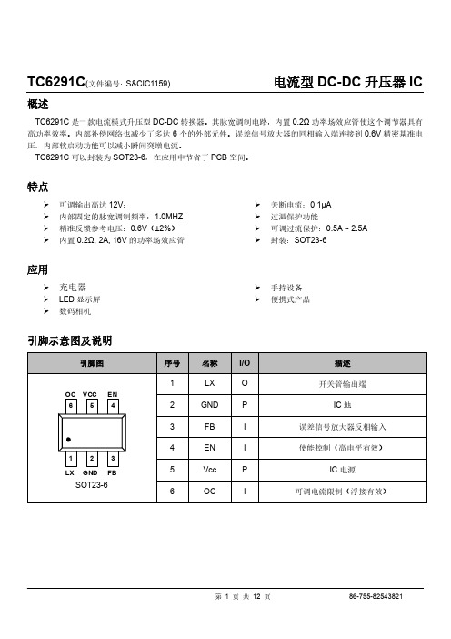
TC6291C (文件编号:S&CIC1159) 电流型DC-DC 升压器IC概述TC6291C 是一款电流模式升压型DC-DC 转换器。
其脉宽调制电路,内置0.2Ω功率场效应管使这个调节器具有高功率效率。
内部补偿网络也减少了多达6个的外部元件。
误差信号放大器的同相输入端连接到0.6V 精密基准电压,内部软启动功能可以减小瞬间突增电流。
TC6291C 可以封装为SOT23-6,在应用中节省了PCB 空间。
特点可调输出高达12V ;内部固定的脉宽调制频率:1.0MHZ 精准反馈参考电压:0.6V (±2%) 内置0.2Ω, 2A, 16V 的功率场效应管关断电流:0.1µA 过温保护功能可调过流保护:0.5A ~ 2.5A封装:SOT23-6应用充电器 LED 显示屏 数码相机 手持设备 便携式产品引脚示意图及说明TC6291C (文件编号:S&CIC1159) 电流型DC-DC 升压器IC功能框图21DCB0.3V0.6V短路比较器误差放大器UVLO关机电路软启动脉宽调制比较器振荡器斜率补偿OT P控制和驱动逻辑可调电流限制电流检测放大器Σ12345610KΩ - 100KΩ2.5A - 0.5A最大额定值参数 符号 测试条件最小值 典型值 最大值 单位 电源电压 Vcc 0 6 V LX 电压 Vlx 0 16 V EN 、FB 电压0 6 V 功耗 Pd SOT23-6@Ta=25℃455 m W 热阻 θJA SOT23-6+220 ℃/W 结温 Tj +150 ℃ 工作温度 Top -40 +85 ℃ 储存温度 Tst -65 +150 ℃ 管脚温度锡焊,10秒+260℃TC6291C(文件编号:S&CIC1159)电流型DC-DC升压器IC 典型工作特性(Vcc=3.3V,Vout=5V,Ta=25℃,除特殊说明外)效率VS输出电流电流限制VS外部电阻(Roc)工作频率VS输入电压工作频率VS温度参考电压VS输入电压参考电压VS输出电流TC6291C(文件编号:S&CIC1159)电流型DC-DC升压器IC 静态电流VS输入电压平均供电电流VS输入电压功能描述操作TC6291C是电流模式升压转换器。
稳压IC_DC-DC__大全(带图)

稳压IC DC-DC 大全(带图)AMS117-3.3V 1A VIN<12VAMS 117-2.5V 1A VIN<12VAMS 117-1.8V 1A VIN<12VAMS 117-5V 1A VIN<12VAMS117-ADJ 1A VIN<12V(DC/DC) DC-DCTD1410 2A VIN<20V MP1580 2A VIN<25VMP1583 3A VIN<23V MPS1410/9141 2A VIN<15VMP1591 2A VIN<32V MP34063 1.5A VIN<40VACT4060 2A VIN<20V MP1482/MP2307 2A VIN<18VMP1484 3A VIN<23V TD6811 1.2A VIN<6VAP1513 2A VIN<18V7805 正5V稳压器(1A) 7805中文资料.pdf下载7806 正6V稳压器(1A)7808 正8V稳压器(1A)7809 正9V稳压议(1A)7809中文资料7812 正12V稳压器(1A) 7812中文资料7815 正15V稳压器(1A) 三端稳压器7815中文资料7818 正18V稳压器(1A)7824 正24V稳压器(1A)78L05 正5V稳压器(100ma)78L06 正6V稳压器(100ma)78L08 正8V稳压器(100ma)78L09 正9V稳压器(100ma)78L12 正12V稳压器(100ma)78L15 正15V稳压器(100ma)78L18 正18V稳压器(100ma)78L24 正24V稳压器(100ma)7905 负5V稳压器(1A)7906 负6V稳压器(1A)7908 负8V稳压器(1A)7909 负9V稳压器(1A)7912 负12V稳压器(1A)7915 负15V稳压器(1A)7918 负18V稳压器(1A)7924 负24V稳压器(1A)***************************************79L05 负5V稳压器(100ma)79L06 负6V稳压器(100ma)79L08 负8V稳压器(100ma)79L09 负9V稳压器(100ma)79L12 负12V稳压器(100ma)79L15 负15V稳压器(100ma)79L18 负18V稳压器(100ma)79L24 负24V稳压器(100ma)***************************************LM1575T-3.3 3.3V简易开关电源稳压器(1A)LM1575T-5.0 5V简易开关电源稳压器(1A)LM1575T-12 12V简易开关电源稳压器(1A)LM1575T-15 15V简易开关电源稳压器(1A)LM1575T-ADJ 简易开关电源稳压器(1A可调1.23 to 37)LM1575HVT-3.3 3.3V简易开关电源稳压器(1A)LM1575HVT-5.0 5V简易开关电源稳压器(1A)LM1575HVT-12 12V简易开关电源稳压器(1A)LM1575HVT-15 15V简易开关电源稳压器(1A)LM1575HVT-ADJ 简易开关电源稳压器(1A可调1.23 to 37)**************************************LM2575T-3.3 3.3V简易开关电源稳压器(1A)LM2575T-5.0 5V简易开关电源稳压器(1A)LM2575T-12 12V简易开关电源稳压器(1A)LM2575T-15 15V简易开关电源稳压器(1A)LM2575T-ADJ 简易开关电源稳压器(1A可调1.23 to 37)LM257HVT-3.3 3.3V简易开关电源稳压器(1A)LM2575HVT-5.0 5V简易开关电源稳压器(1A)LM2575HVT-12 12V简易开关电源稳压器(1A)LM2575HVT-15 15V简易开关电源稳压器(1A)LM2575HVT-ADJ 简易开关电源稳压器(1A可调1.23 to 37)**************************************LM2576T-3.3 3.3V简易开关电源稳压器(3A)LM2576T-5.0 5.0V简易开关电源稳压器(3A)LM2576T-12 12V简易开关电源稳压器(3A)LM2576T-15 15V简易开关电源稳压器(3A)LM2576T-ADJ 简易开关电源稳压器(3A可调1.23V to 37V)LM2576HVT-3.3 3.3V简易开关电源稳压器(3A)LM2576HVT-5.0 5.0V简易开关电源稳压器(3A)LM2576HVT-12 12V简易开关电源稳压器(3A)LM2576HVT-15 15V简易开关电源稳压器(3A)LM2576HVT-ADJ 简易开关电源稳压器(3A可调1.23V to 37V) **************************************LM2930T-5.0 5.0V低压差稳压器LM2930T-8.0 8.0V低压差稳压器LM2931AZ-5.0 5.0V低压差稳压器(TO-92)LM2931T-5.0 5.0V低压差稳压器LM2931CT 3V to 29V低压差稳压器(TO-220,5PIN)LM2940CT-5.0 5.0V低压差稳压器LM2940CT-8.0 8.0V低压差稳压器LM2940CT-9.0 9.0V低压差稳压器LM2940CT-10 10V低压差稳压器LM2940CT-12 12V低压差稳压器LM2940CT-15 15V低压差稳压器**************************************LM123K 5V稳压器(3A)LM323K 5V稳压器(3A)LM117K 1.2V to 37V三端正可调稳压器(1.5A)LM317LZ 1.2V to 37V三端正可调稳压器(0.1A)LM317T 1.2V to 37V三端正可调稳压器(1.5A)LM317K 1.2V to 37V三端正可调稳压器(1.5A)LM133K 三端可调-1.2V to -37V稳压器(3.0A)LM333K 三端可调-1.2V to -37V稳压器(3.0A)LM337K 三端可调-1.2V to -37V稳压器(1.5A)LM337T 三端可调-1.2V to -37V稳压器(1.5A)LM337LZ 三端可调-1.2V to -37V稳压器(0.1A)LM150K 三端可调1.2V to 32V稳压器(3A)LM350K 三端可调1.2V to 32V稳压器(3A)LM350T 三端可调1.2V to 32V稳压器(3A)LM138K 三端正可调1.2V to 32V稳压器(5A)LM338T 三端正可调1.2V to 32V稳压器(5A)LM338K 三端正可调1.2V to 32V稳压器(5A)LM336-2.5 2.5V精密基准电压源LM336-5.0 5.0V精密基准电压源LM385-1.2 1.2V精密基准电压源LM385-2.5 2.5V精密基准电压源LM399H 6.9999V精密基准电压源LM431ACZ 精密可调2.5V to 36V基准稳压源LM723 高精度可调2V to 37V稳压器LM105 高精度可调4.5V to 40V稳压器LM305 高精度可调4.5V to40V稳压器MC1403 2.5V基准电压源MC34063 DC-DC直流变换器mc34063中文资料pdf SG3524 脉宽调制开关电源控制器sg3524中文资料TL431 精密可调2.5V to 36V基准稳压源tl431a pdf 中文资料TL494 脉宽调制开关电源控制器tl494中文资料pdf下载TL497 频率调制开关电源控制器tl497/tl497A pdf datasheet TL7705 电池供电/欠压控制器。
慧蕴电子 高效DC DC升压控制器 HY3100 说明书
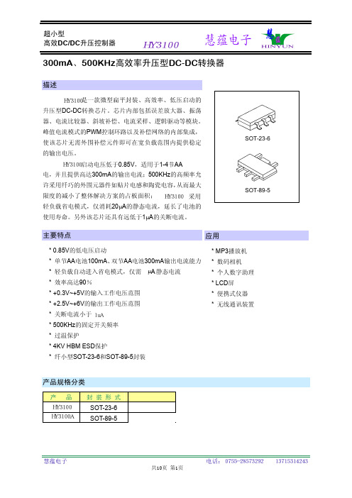
300mA、500KHz高效率升压型DC-DC转换器描述是一款微型扁平封装、高效率、低压启动的升压型DC-DC转换芯片。
芯片内部包括误差放大器、振荡器、电流比较器、斜坡补偿、电流采样、逻辑驱动等模块。
峰值电流模式的PWM控制环路以及补偿网络的内部集成,使该芯片无需外围补偿元件即可在宽负载范围内提供稳定的输出电压。
SOT-23-6启动电压低于0.85V,适用于1-4节AA电,并且提供高达300mA的输出电流;500KHz的高频率允许采用纤巧的外围元器件如贴片电感和陶瓷电容,从而最大限度的减小了整体解决方案的占板面积;轻负载省电模式,仅消耗20μA的静态电流,延长了电池的使用寿命。
另外该芯片还具有远低于1μA的关断电流。
SOT-89-5主要特点* 0.85V的低电压启动* 单节AA电池100mA、双节AA电池300mA输出电流能力* 轻负载自动进入省电模式,仅需μA静态电流* 效率高达90%* +0.3V~+5V的输入工作电压范围* +2.5V~+6V的输出工作电压范围* 关断电流小于* 500KHz的固定开关频率* 过温保护* 4KV HBM ESD保护* 纤小型SOT-23-6和SOT-89-5封装应用* MP3播放机* 数码相机* 个人数字助理产品规格分类* LCD屏* 便携式仪器* 无线通讯装置产品封装形式SOT-23-6SOT-89-5共10页 第1页1uAHY3100HY3100HY3100 采用HY3100HY3100A内部框图极限参数 (T amb=25°C)参 数 参 数 范 围 单 位V DD工作端电压范围-0.3 ~ +6 V开关端电压范围-0.3 ~ +6 V使能端电压-0.3 ~ +6 V反馈端电压-0.3 ~ +6 V°C工作环境温度-40 ~ + 85贮存温度-65 ~ +125 °C电气参数 (除非特别注明,否则T amb =25°C,VI N=1.5V,V DD=3.3V,负载电流为0)参 数 符 号 测 试 条 件 最小值典型值 最大值 单位最小启动电压V ST I L=1mA --0.850.9V 最小输入电压V INMIN启动之后的VIN仅受输出功率限制-- 0.3 0.4 V工作电压范围V DD 2.5 --6 V反馈端电压V FB-- 1.23 V静态电流(轻载省电模式)I switch off FB=1.4V -- 20 30 μA(见下页)共10页 第2页(接上页)参 数 符 号 测 试 条 件最小值典型值 最大值 单位静态电流(关机状态模式)I st EN=0V -- 0.1 1 μA静态电流(PWM工作模式)I Q测试V DD端电流,无开关-- 300 360 μA进入省电模式的负载门限I load L= 4.7μH -- 7.5 -- mA输出电压线性调整率△V LINE 1V≤V IN≤3 V -- 2 10 mV/V输出电压负载调整率△V LOAD 1mA≤ I L ≤100mA --0.11mV/mA开关频率Fs -- 450 500 550 KHz最大占空比D MAX FB= 1.1V 90 95 %NMOS开关管导通电阻R ON V DD= 3.3V --0.40.5ΩNMOS开关管漏电流I leak V LX=5V --0.1ANMOS开关管限流值I LIMIT0.75 1.25 AEN输入高电平V H -- 1 VEN输入低电平V L -- -- 0.35 V热关断温度T j(sd)-- 150 C热关断迟滞温度T hyst C-- 20管脚排列图管脚描述管脚号管脚名称I/O 管脚说明1 1 ENI使能输入端。
摩尔晓光DC DC转换器产品说明书
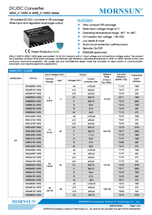
1W isolated DC/DC converter in SIP package Wide input and regulated dual/single outputPatent Protection RoHSFEATURES●Ultra compact SIP package ●Wide input voltage range (2:1)●Operating temperature range:-40℃to +85℃●I/O Isolation test voltage:1.5K VDC ●Low ripple &noise●Short-circuit protection (self-recovery)●Remote On/Off ●EN62368approvedWRA_S-1WR2&WRB_S-1WR2series are isolated 1W DC-DC products with 2:1input voltage and conventional voltage output.The product has a relatively compact SIP-8plastic package,and features high efficiency,operating temperature of -40℃to +85℃,remote control,and continuous short-circuit protection.The smaller size and cost-effective design make the converter an ideal solution in communication,instruments,and industrial electronics applications.Selection GuideCertificationPart No.Input Voltage (VDC)OutputRipple &Noise (mVp-p)Typ./Max.Full Load Efficiency (%)Min./Typ.Capacitive Load ②(µF)Max.Nominal (Range)Max.①Voltage(VDC)Current (mA)Max./Min.CEWRA0505S-1WR25(4.5-9)11±5±100/±570/10071/731000WRA0512S-1WR2±12±42/±274/76470WRA0515S-1WR2±15±33/±273/75330WRB0503S-1WR2 3.3303/1569/711800WRB0505S-1WR25200/1070/722200WRB0512S-1WR21283/474/761000WRB0515S-1WR21567/373/75680WRB0524S-1WR22442/271/73470WRA1205S-1WR212(9-18)20±5±100/±5100/15076/781000WRA1212S-1WR2±12±42/±279/81470WRA1215S-1WR2±15±33/±276/78330WRB1203S-1WR2 3.3303/1573/752700WRB1205S-1WR25200/1075/772200WRB1209S-1WR29111/677/791800WRB1212S-1WR21283/477/791000WRB1215S-1WR21567/378/80680WRB1224S-1WR22442/274/76470WRA2405S-1WR224(18-36)40±5±100/±570/10077/791000WRA2409S-1WR2±9±56/±377/79680WRA2412S-1WR2±12±42/±277/79470WRA2415S-1WR2±15±33/±277/79330WRB2403S-1WR2 3.3303/1573/752700WRB2405S-1WR25200/1075/772200WRB2412S-1WR21283/476/781000WRB2415S-1WR21567/376/78680WRB2424S-1WR22442/275/77470WRA4805S-1WR248(36-75)80±5±100/±5100/15074/761000WRA4812S-1WR2±12±42/±276/78470WRA4815S-1WR2±15±33/±278/80330WRB4803S-1WR23.3303/1573/752700Input SpecificationsItemOperating Conditions Min.Typ.Max.Unit Input Current (full load/no-load)5VDC Input--281/40290/60mA12VDC Input --111/15114/3024VDC Input --55/657/10mA48VDC Input --27/428/6Reflected Ripple Current5VDC Input--30--12VDC Input --40--24VDC Input --55--48VDC Input --45--Surge Voltage (1sec.max.)5VDC Input-0.7--12VDC12VDC Input -0.7--2524VDC Input -0.7--5048VDC Input -0.7--100Starting Voltage5VDC Input---- 4.512VDC Input ----924VDC Input ----1848VDC Input----36Input Filter Filter capacitor Hot PlugUnavailableCtrl*Module onCtrl pin open (high resistance)Module offCtrl pin pulled high(current 5-10mA typ.into Ctrl.)Note:*For use of Ctrl,please refer to the “design reference”in this manual.Output SpecificationsItemOperating ConditionsMin.Typ.Max.UnitOutput Voltage Accuracy5%-100%load ,Input voltage range 3.3V/5V output --±2±5%others--±1±3No-load Output Voltage Accuracy Input voltage range--±1.5±5Linear Regulation Input voltage variation from low to high at full load--±0.2±0.5Load Regulation 5%-100%load--±0.4±0.75Transient Recovery Time 25%load step change --0.52ms Transient Response Deviation --±2.5±5%Temperature Coefficient Full load--±0.02±0.03%/℃Short Circuit ProtectionContinuous,self-recoveryNote:*The ”parallel cable”method is used for Ripple and Noise test,please refer to DC-DC Converter Application Notes for specific information.General SpecificationsItemOperating ConditionsMin.Typ.Max.UnitIsolationInput-output,with the test time of 1minute and the leak current lower than 1mA 1500----VDC Insulation Resistance Input-output,isolation voltage 500VDC 1000----M ΩIsolation Capacitance Input-output,100KHz/0.1V --120--pF Operating Temperature see Fig.1-40--+85℃Storage Temperature-55--+125℃Pin Soldering Resistance Temperature Soldering spot is1.5mm away from case for10seconds----+300℃Storage Humidity Non-condensing----95%RH Switching Frequency(PFM Mode)Full load,nominal input voltage--200--KHz MTBF MIL-HDBK-217F@25℃1000----K hoursMechanical SpecificationsCase Material Black flame-retardant and heat-resistant plasticDimension22.00×9.50×12.00mmWeight 4.5g(Typ.)Cooling Method Free air convectionElectromagnetic Compatibility(EMC)EMI CE CISPR32/EN55032CLASS B (see Fig.3-②for recommended circuit) RE CISPR32/EN55032CLASS B(see Fig.3-②for recommended circuit)EMS ESD IEC/EN61000-4-2Contact±4KV perf.Criteria B RS IEC/EN61000-4-310V/m perf.Criteria A EFT IEC/EN61000-4-4±2KV(see Fig.3-①for recommended circuit)perf.Criteria B Surge IEC/EN61000-4-5line to line±2KV(see Fig.3-①for recommended circuit)perf.Criteria B CS IEC/EN61000-4-63Vr.m.s perf.Criteria A Voltage dips,short interruptionsand voltage variations immunity IEC/EN61000-4-290%,70%perf.Criteria BTypical Characteristic CurvesFig1Design ReferenceAll DC-DC converters of this series are tested before delivery using the recommended circuit shown in Fig.2.Input and/or output ripple can be further reduced by appropriately increasing the input &output capacitor values Cin and Cout and/or by selecting capacitors with a low ESR (equivalent series resistance).Also make sure that the capacitance is not exceeding the specified max.capacitive load value of the product.Single1V inG N C d C in 1C in 2L in 2687Vo0VC S 3RD 1V cL c C o u tDual+Vo 0V Cout 687CoutLoutLout-VoCin1Vin21Lin3VcRIc D1Cd Cin2Vin5VDC&12VDC 24VDC&48VDC Cin1100µF/25V 10µF/100V Cin247µF/25V1µF/100VLin 4.7µH-12µH Cs10µF-22µF/50VCout Vo(3/±3/5/±5/9/±9V):100µF/16VVo(12/±12/15/±15V):100µF/25V Vo(24/±24V):100µF/50VLout 2.2μH-10μH Cd47nF/100V2.EMC compliance circuitLDM1②C0MOVFUSE①C1+VinGND+Vo-Vo (0V)DC/DCLOADC2CY CtrlCd D1R③CtrlVin1C3Parameter description:ModelVin:5VDC Vin:12VDC Vin:24VDC Vin:48VDC FUSE Slow blown fuses according to the actual input current selections of the clientsMOV --S14K25S14K35S14K60C01000µF/16V1000µF/25V 330µF/50V330µF/100V C1 4.7µF/50V4.7µF/100V LDM112µHC2 4.7µF/50V4.7µF/100VC3Refer to the Cout in Fig.2CY11nF/2KV D160V/1AR In accordance with the formula:300-0.1--CD C I V V R =Cd47nF/100VNotes:①For EMC tests we use Part ①in Fig.3for immunity and part ②for emissions test.Selecting based on needs.②V C is the voltage of the Ctrl end relative to the GND of the input grounding;V D is the positive-going conduction pressure drop of D1;I C is the current flows into the Ctrl end and its value is generally 5-10mA,see Fig.3-③for the peripheral circuit of Ctrl end;③If there is no recommended parameters,no external component is required.3.Ctrl endThe modules are of normal output when the Ctrl end is suspended or of high resistance;the modules turn off when connecting with high level (relative to the input grounding);notice that the current flows into the pin shall be 5-10mA,the modules will be permanently damaged if the current exceeds its max.value (20mA in general).The value of R can be derived as follows:300-0.1--C D C I V V R =For Detailed parameter,please refer to EMC solution-recommended circuit in this manual.4.Input currentWhen the electricity is provided by the unstable power supply,please make sure that the range of the output voltage fluctuation and the ripple voltage of the power supply do not exceed the indicators of the modules.Input current of power supply should afford the flash startup current of this kind of DC/DC module(see Fig.5).Generally:Vin=5V series Iave =445mAVin=12V series lave =205mA Vin=24V series lave =104mA Vin=48V series lave =53mAInput Voltage (V)Input Voltage scopeIaveFig.55.Output load requirementsWhen using,the minimum load of the module output should not be less than 5%of the nominal load.In order to meet the performance parameters of this datasheet,please connect a 5%dummy load in parallel at the output end,the dummy load is generally a resistor,please note that the resistor needs to be used in derating.6.For more information please find DC-DC converter application notes on Dimensions and Recommended LayoutNotes:1.For additional information on Product Packaging please refer to .Packaging number:58210004;2.Recommend to use module with more than5%load,if not,the ripple of the product may exceeds the specification,but does notaffect the reliability of the product;3.The recommended unbalance degree of the dual output module load is≤±5%;if the degree exceeds±5%,then the productperformance cannot be guaranteed to comply with all parameters in the datasheet.Please contact our technicians directly for specific information;4.The maximum capacitive load offered were tested at input voltage range and full load;5.Unless otherwise specified,parameters in this datasheet were measured under the conditions of Ta=25℃,humidity<75%RH with nominalinput voltage and rated output load;6.All index testing methods in this datasheet are based on company corporate standards;7.We can provide product customization service,please contact our technicians directly for specific information;8.Specifications are subject to change without prior notice.Mornsun Guangzhou Science&Technology Co.,Ltd.Address:No.5,Kehui St.1,Kehui Development Center,Science Ave.,Guangzhou Science City,Huangpu District,Guangzhou,P.R.China Tel:86-20-38601850Fax:86-20-38601272E-mail:***************。
HMC1002中文芯片资料
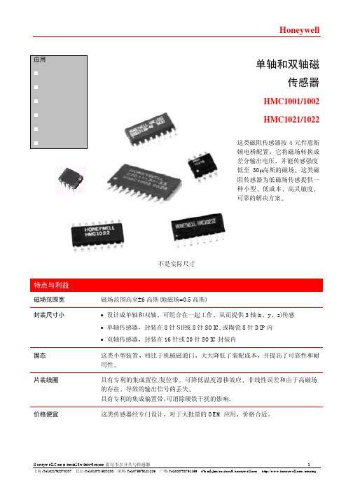
特点与利益
磁场范围宽 封装尺寸小
固态 片装线圈
价格便宜
不是实际尺寸
磁场范围高至±6 高斯(地磁场=0.5 高斯) • 设计成单轴和双轴 可组合在一起工作 从而提供 3 轴(x y z)传感 • 单轴传感器 封装在 8 针SIP或 8 针 SOIC, 或陶瓷 8 针 DIP 内 • 双轴传感器 封装在 16 针或 20 针 SOIC 封装内 这类小型装置 相比于机械磁通门 大大降低了装配成本 并提高了可靠性和耐 用性 具有专利的集成置位/复位带 可降低温度漂移效应 非线性误差和由于高磁场 的存在 导致的输出信号的丢失 具有专利的集成偏置带,可消除硬铁干扰的影响. 这类传感器经专门设计 对于大批量的 OEM 应用 价格合适
上海: Tel:021-62370237 北京: Tel:010-84583280 深圳: Tel:0755-5181226
广州: Tel:020-38791169
e-mail:jian.bo.zhou@
3
/sensing
线性磁场传感器
从 S/R+至 S/R-之间测量
2 µs 电流脉冲
灵敏度开始降低 使用 S/R 脉冲来恢复灵敏度
TA=-40 至 125°C
V 电桥=8V
I 电桥=5mA
TA=-40 至 125°C
无置位/复位I 电Fra bibliotek=5mA有置位/复位
V 电桥=8V -40 至 125°C
垂直磁场=1 高斯
无置位/复位
有置位/复位
应用 罗盘定向 导航系统 飞行高度基准 交通流量检测 医疗设备 非接触开关
Honeywell
单轴和双轴磁 传感器
HMC1001/1002
HMC1021/1022
DC升压恒流IC 宽电压100V

H6701 是一款高效率、高精度的升 压型大功率 LED 恒流驱动控制芯片。
H6701 内置高精度误差放大器,固 定关断时间控制电路,恒流驱动电路等, 特别适合大功率、多个高亮度 LED 灯串恒 流驱动。
H6701 采用固定关断时间的控制方 式,关断时间可通过外部电容进行调节, 工作频率可根据用户要求而改变。
典型值 最大值 单位
ቤተ መጻሕፍቲ ባይዱ
5.5
V
3.2
V
1.3
mA
200
uA
250
260
mV
250
260
mV
620
ns
V
0.8
V
50
ns
50
ns
250
ns
135
oC
5
升压型LED驱动器H6701
应用指南
概述
H6701 是一款升压型大功率 LED 恒流驱动控制 IC,采用固定关断时间的峰值电流模式 控制方式。
芯片内部由误差放大器、PWM 比较器、电感峰值电流限流、固定关断时间控制电路、 PWM 逻辑、功率管驱动、基准等电路单元组成。
系统工作频率 FS
系统工作频率FS由下式确定:
FS
=
VI N VOUT ∗TOFF
其中VIN、VOUT分别是系统输入和输出电压。
6
升压型LED驱动器H6701
电感取值
流过电感的纹波电流大小与电感取值有关。工作于连续模式时,电感纹波电流由下式确 定:
ΔI L
=
VOUT − VIN L
∗ TOFF
增大电感值纹波电流会减小,反之增大。
典型应用电路图
特点
升压型LED驱动器H6701
ME2106 升压ic (最新版中文资料)
Vout Vin 。 Vout
First, selection of inductor
Make sure DC-DC can natural work firstly in the model of the minimum continuous current that is Lmin,Lmin≧
Q、2355558460 13620971652
Selection Guide:
Applications:
Power source for high-power LED Power source for invariant current
1 Watt Step up DC-DC White LED Driver ME2106 Series
(B) Drive more serial two parallel white light LED with low power
Suggestions:
You can increase the output capacitor properly for improve to the characteristic of the output invariant current ( for example:150uF or 200uF)。 To avoid the feedback voltage excursion, please wear the ring with static electricity and the electric iron connect to ground when the soldering。
1 Watt Step up DC-DC White LED Driver ME2106 Series
DC-DC 电源转换器说明书

DC TO AC POWER INVERTERPWRNV1250W INSTRUCTION MANUALSAVE THIS MANUALYou will need the manual for the safety warnings and precautions, assembly instructions, operating and maintenance procedures, parts list and diagram. Keep your invoice with this manual. Write the invoice number on the inside of the front cover. Keep the manual and invoice in a safe and dry place for future reference.Basic Operation•Make sure that you choose the right operating voltage for both input and output of the inverter.•When unpacking, make sure that the inverter is in good condition. If any parts are missing or broken, please call AIMS Power, Inc. at the number found on the warranty card.•Place the power inverter on a flat surface. Make sure it has adequate ventilation and is not in direct sunlight. Fasten the inverter securely to the surface, using screws or some othermeans. If holes are to be drilled, follow safe, proper installation techniques.Before you connect the battery cables, make sure the power switch is in the off position. Connect Red (+) battery cable to Red (+) inverter terminal. Connect Black (-) battery cable to Black (-) inverter terminal. Connect Red (+) battery cable to Red (+) battery terminal. Connect Black (-) battery cable to Black (-) battery terminal. Alligator clamp cables may be used but only to connect to the battery.Do not use clamps on inverter terminals. Alligator clamps are not a permanent solution. You may see a spark during connection.•Connect the ground cable to an earth ground, such as a metal water pipe or to the vehicle ground when used in a vehicle if the inverter includes a ground port.•Turn the power switch to the on position, which is located on the front of the inverter. The green LED light will confirm that AC power is present.•Before plugging the equipment into the inverter, make sure the equipment AND the inverter are off. Turn inverter on first, then turn on the equipment.•The power inverter can be used either while the engine is running or off.Warnings•Unplug the inverter when it is not in use.•If the AC inverter makes a beeping sound, turn off the equipment, unplug the inverter and restart the vehicle’s engine. The beeping sound is simply the low-battery warning, which indicates that the voltage of your battery is getting low. If you do not re-start your engine and continue operating the inverter, the inverter will automatically shut off, leavingyour vehicle's battery at about 10. 5 VDC. This will allow you to start your engine and resumeoperation of the inverter. It also reduces the fear of being stranded with a dead battery(dependent on health of battery).•This device should only be serviced by a qualified technician. This item does not have any serviceable parts.•Prevent body contact with grounded surfaces such as pipes, radiators, ranges, and refrigerator enclosures during installation.•Do not operate the inverter if under the influence of alcohol or drugs. Read warning labels on prescriptions to determine if your judgement or reflexes are impaired while taking drugs. Ifthere is any doubt, do not operate the inverter.•People with pacemakers should consult their physician(s) before using this product.Electromagnetic fields in close proximity to a heart pacemaker could cause interference to or failure of the pacemaker.•Keep children away. Children must never be allowed in the work area. Do not let them handle machines, tools, or extension cords.•Store idle equipment. When not in use, inverter must be stored in a dry location to prevent rust. Always lock up tools and the inverter and keep out of reach of children.•Size the inverter properly. Size the inverter for the surge rating of your equipment. The inverter’s continuous rating should be MORE than the surge rating of your equipment.Example: Power tool runs at 1500 watts but surges at 2500 watts. You should use an inverter >3000 watts.•Keep the inverter well-ventilated. Do not place any objects on top of or next to the inverter or allow anything to cover the cooling fans; doing so can cause the inverter to overheat,causing a potential fire hazard and/or damage to the inverter. Leave adequate ventilationspace underneath the inverter as well; thick carpets or rugs can obstruct air flow, causing the inverter to overheat.•Avoid unintentional starting. Be sure the switch is in the OFF position when not in use and before plugging in any appliance.Note: Performance of this unit may vary depending on the available battery power or appliance wattage.Warning: The warnings, cautions, and instructions discussed in this instruction manual cannot cover all possible conditions and situations that may occur. It must be understood by the operator that common sense and caution are factors which cannot be built into this product, but must be supplied by operator. Guard against electric shock. Do not open the metal case; risk of electric shock.Battery Use•To avoid over-discharging your vehicle battery, we recommend running your engine for 10-20 minutes to recharge the vehicle's battery if battery voltage drops <11V.•To properly size your battery, use the following formula: Volts * Amps = Watts or Watts/Volts = Amps. Example: 1000 watt inverter / 12 volts DC = 83.3 DC amps. In this example, you willneed 83.3 amps to power a 1000 watt load for 1 hour. If you need to power 1000 watts for 2hours you will need 83.3 * 2 = 166.66 DC amps available. A 100 amp hour battery will giveyou 100 amps / 166.66 = .6 hours so you will need two batteries if using 100 amp battery.This is if you fully deplete your batteries. We do NOT recommend fully depleting yourbatteries. This is just an example. Your power requirements may be different.•If you choose to use a female 12 Volt DC adapter for your inverter or to the inverter make sure wire size is correct.•IF YOU CONNECT THE WIRES TO THE INCORRECT TERMINALS, YOU WILL REVERSE THE POLARITY AND DAMAGE THE INVERTER.•REVERSED POLAR ITY WILL INSTANTLY VOID THE WARRANTY OF YOUR INVERTER, SO BE CAREFUL TO CONNECT YOUR INPUT WIRES PROPEPLY.•If you choose to operate a battery charger to replenish your battery’s voltage, be sure to check with charger manufacture before damaging the charger.•CONNECTING THE INVERTER’S DC INPUT TO A BATTERY CHARGER WILL VOID THE WARRANTY, AND MAY DAMAGE THE INVERTER.•Make sure that the battery voltage does not exceed 15 volts DC.•CONNECTING THE INVERTER TO A DC POWER SOURCE GREATER THAN 15 VDC WILL VOID THE WARRANTY, AND MAY DAMAGE THE INVERTER.CablesWe recommend that you refrain from using battery cables longer than 12 feet between the DC power source and the DC input of the inverter. Longer battery cables on the DC input will create a voltage drop which results in a reduction of efficiency and output. If you require more than 12 feet, use a bigger cable. We recommend using an extension cord between the AC output and AC appliance. You may use up to 100ft, high quality extension cord. A longer cord may result in reduced output. See Specifications chart for recommended battery cable size.Digital Bar DisplayThe digital bar display displays battery DC voltage and DC current. The current should always be in the green zone. The inverter will operate for several minutes when thecurrent is in the yellow zone. Operation in the red zone of the display will result in protective inverter shutdown. NOTE: The bar display will only monitor DC current and voltage not AC. If you need to measure AC output you will need to use a TRUE RMS MULTI METER.Remote On/Off SwitchSome models include a remote port. An AIMS remote on/off switch may be connected to the remote port. The optional remote on/off switch is a convenient option to turn the inverter on/off if the inverter is installed in a hard to reach area. Make sure the inverter is turned off before installing the remote switch. Simply plug the switch into the remote jack. There are several ways to mount the remote switch. Remote switch comes with 4 pre-drilled holes for mounting. Remote part # REMOTEHF.Measuring the AC VoltageThe output waveform of the inverter is a MODIFIED SINE WAVE. If you choose to measure the AC output voltage, you must use a TRUE RMS MULTI METER. Using any other type of voltage measuring device will result in an AC voltage reading of 10 to 30 volts lower than actual voltage. When using a true RMS multi meter, you will get an accurate reading.SAFETY PRECAUTIONS•Do not open the case of the inverter. The high voltage inside the unit is the same type of power as your electrical outlets at home.•Do not let the cord of the inverter, or any appliance cord get wet. If you are operating the inverter in a moving vehicle, we recommend that you secure the inverter to prevent it fromshifting around while the vehicle is moving.•Do not operate this inverter in or around water. Water can damage the inverter, and water damage is not covered under warranty. Also, do not operate the inverter with wet hands. The AC voltage of the unit makes it an electrical shock hazard if operated with wet hands.•Allow at least one inch of clearance around the Inverter for air flow. Ensure the ventilation openings on the rear and bottom of the unit are not obstructed.•Do not connect the inverter directly to another AC power source. Damage may result, and such damage will void the inverter warranty.•Know the wattage requirements of your appliance. Use only those appliances which are limited by the capacity of this unit.•Use common sense. This device produces power just like your wall outlets at home and should be treated seriously. Keep it away from children.•Reversed polarity of AC power outlet LINE /NEUTRAL will void the warranty.•If there is anything wrong with the inverter, disconnect all of the power and contact technical support.If the Inverter does not appear to be functioning properly, check the following possible causes:•Poor contact: Clean contact parts thoroughly.•If the low battery alarm sounds, this means the input voltage is too low and battery needs to be recharged.•If you are getting a low output voltage, try reducing the load to minimize watts. You may have overloaded the inverter. Reduce your load. Also, keep input voltage above 10.5 volts tomaintain a constant flow of power.•If you are not getting any power output, turn the power switch Off and On again, until the green power light comes on. Your devices may draw too much power to operate them. Theinverter may be in thermal shutdown. Let it cool down and make sure there is adequateventilation around the unit.•If the green light turns red one of the following has happened:A.input voltage is too lowB.input voltage is too highC.short circuitD.inverter is close to overload•Battery voltage is too low: Start the engine to recharge the battery. Replace or recharge battery if needed.•Shuts down on overload: Reduce the wattage of your load.•Thermal shutdown: Under heavy loads for extended period, the inverter will shut down to prevent damage from excess heat. Simply reduce your load and allow theInverter to cool down.•Low-battery shutdown: Recharge your battery and resume operation.Very little maintenance is required to keep your inverter operating properly. You should disconnect input power first and then clean the exterior of the unit periodically with a dry cloth to prevent accumulation of dust and dirt. At the same time, tighten the screws on the DC input terminals.PLEASE READ THE FOLLOWING CAREFULLYNeither the manufacturer nor distributor makes any representation or warranty of any kind to the buyer that he or she is qualified to make any repairs to the product or that he or she is qualified to replace any parts of the product. In fact, the manufacturer and/or distributor expressly states that all repairs and parts replacements should be undertaken by certified and licensed technicians and not by the buyer. The buyer assumes all risk and liability arising out of his or her repairs to the original product or replacement parts thereto, or arising out of his or her installation of replacement parts thereto.WARRANTYAIMS Corp., Inc. dba AIMS Power Warranty Instructions:This product is designed using the most modern digital technology and under very strict quality control and testing guidelines. If, however, you feel this product is not performing as it should, please contact us:**************************(775)359-6703We will do our best to resolve your concerns. If the product needs repair or replacement, make sure to keep your receipt/invoice, as that will need to be sent back along with the package and RMA# prepaid to AIMS. You have a full 1 year warranty from date of purchase.This warranty is valid worldwide with the exception that freight and duty charges incurred outside the contiguous 48 United States will be prepaid by customer.Except as provided above, AIMS makes no warranty of any kind, express or implied, including without limitation the implied warranties of merchantability and fitness for a particular purpose. In no event shall AIMS be liable for indirect, special or consequential damages. This warranty only applies to AIMS Power branded products. All other name brand products are warranted by and according to their respective manufacturer. Please do not attempt to return non-AIMS Power branded products to AIMS Power.For additional products such as:-Modified sine wave inverters-Pure sine wave inverters-Low Frequency Inverters-Solar Charge Controllers-Micro Grid Tied Inverters-Inverter Chargers and Automatic transfer switches-Converters DC-DC-Custom cut cables-Batteries-Solar Panels & RacksPlease visit our web site: Tofindoutwheretobuyanyofourproducts,youmayalsoe-mail:************************ (775)359-6703.。
ME3101 500MA DCDC 升压ic中文资料
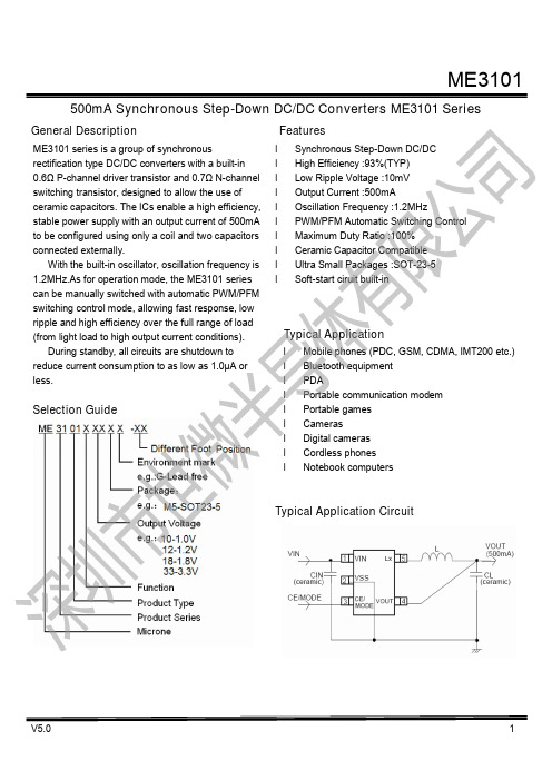
500mA Synchronous Step-Down DC/DC Converters ME3101 Series Selection GuidePin ConfigurationME3101AXX ME3101AXX-DSPin AssignmentME3101AXX Pin NumberPin Name Function 1 VIN Power Input2 VSS VSS3 CE/MODE Chip Enable / Mode Switch4 VOUT Output Voltage Sence 5LXSwitching OutputME3101AXX-DS Pin NumberPin Name Function1 CE/MODE Chip Enable / Mode Switch2 VSS VSS3 LX Switching Output4 VIN Power Input 5VOUTOutput Voltage SenceAbsolute Maximum RatingsPARAMETER SYMBOL RATINGS UNITSVIN Pin Voltage Vin -0.3~6.5 VLx Pin Voltage Vlx -0.3~Vin+0.3 VVOUT Pin Voltage Vout -0.3~6.5 V CE / MODE Pin Voltage Vce -0.3~Vin+0.3 V Lx Pin Current Ilx ±1000 mA Power Dissipation(SOT-23-5L) Pd 250 mWOperating Temperature Range T Opr-25~+85 ℃Storage Temperature Range T stg-40~+125 ℃Block DiagramElectrical CharacteristicsME3101A10 ( Unless Otherwise Stated ,VIN=3.0V,FOSC=1.2MHz, Cin=4.7uF,CL=10uF,L=3.3uH,Ta=25℃ ) PARAMETER SYMBOL CONDITIONS MIN. TYP. MAX. UNIT CIRCUIT Output Voltage Vout Vce=Vin,Iout=30mA 0.98 1.0 1.02 V ①OperatingVoltageRangeVin 2 - 6 V ①Maximum OutputCurrentIout.max -500 -mA ①U.V.L.O . Voltage VuvloVce=Vin,Vout=0V,LX Voltage which Lx pinvoltage holding "L" level- 1.2 -V ②Supply Current Idd Vin=Vce=3.0V,Vout=Vout×1.1-55 -uA ③Stand-by Current Istb Vin=3.0V,Vce=0V,Vout=Vout×1.1-0 1 uA ③Frequency FOSC Iout=100mA 1020 1200 1380 KHz ①PFM SwitchCurrentIpfm Vce=Vin,Iout=1mA -180 -mA ①Maximum DutyRatioMaxdty Vce=Vin,Vout=0 100 --%④Minimum DutyRatioMindty Vce=Vout=Vin --0 %④Efficiency EFFI Vce=Vin=2.5V,Iout=100mA-90 -%①Lx SW “H” ON Resistance RlxHVce=0.5Vin,Vce=0V,Ilx=100mA-0.5 1.2 Ω ⑤Lx SW “L” ONResistanceRlxL Vce=0.5Vin,Ilx=100mA -0.6 1.4 Ω -Lx SW “H” LeakCurrent IleakHVin=Vout=5.0V,Vce=0V,Lx=0V-0.01 1 uA ⑥Lx SW “L” Leak Current IleakLVin=Vout=5.0V,Vce=0V,Lx=5V-0.01 1 uA ⑥Current Limit Ilim Vin=Vce=5.0V,Vout=0V -800 -mA ⑦Output Voltage Temperature CharacteristicsVout/(Vout*⊿topr)Iout=30mA,-40℃≤Topr≤85℃-+100 -ppm/℃①CE “H” Voltage VceH Vout=0V 0.7 -Vin V ⑧CE “L” Voltage VceL Vout=0V Vss -0.6 V ⑧CE “H” Current Iceh Vin=Vce=5.5V,Vout=0V -0.1 -0.1 uA ⑧CE “L” Current Icel Vin=5.5V,Vce=0V,Vout=0V-0.1 -0.1 uA ⑧Soft-Start Time Tss Vce=0V~Vin,Iout=1mA 0.5 1.2 3.0 msec ①Latch Time Tlat Vin=Vce=5.0V 1 -20 msec ⑨ME3101A12 ( Unless Otherwise Stated ,VIN=3.0V,FOSC=1.2MHz, Cin=4.7uF,CL=10uF,L=3.3uH,Ta=25℃ ) PARAMETER SYMBOL CONDITIONS MIN. TYP. MAX. UNIT CIRCUIT Output Voltage Vout Vce=Vin,Iout=30mA 1.176 1.2 1.224 V ①OperatingVoltageRangeVin 2 - 6 V ①Maximum OutputCurrentIout.max VIN=2.5V 500 --mA ①U.V.L.O . Voltage VuvloVce=Vin,Vout=0V,LX Voltage which Lx pinvoltage holding "L" level1 1.4 1.78 V ②Supply Current Idd Vin=Vce=3.0V,Vout=Vout×1.1-60 120 uA ③Stand-by Current Istb Vin=3.0V,Vce=0V,Vout=Vout×1.1-0 1 uA ③Frequency FOSC Iout=100mA 1020 1200 1380 KHz ①PFM SwitchCurrentIpfm Vce=Vin,Iout=1mA 100 140 180 mA ①Maximum DutyRatioMaxdty Vce=Vin,Vout=0 100 --%④Minimum DutyRatioMindty Vce=Vout=Vin --0 %④Efficiency EFFI Vce=Vin=2.5V,Iout=100mA-90 -%①Lx SW “H” ON Resistance RlxHVce=0.5Vin,Vce=0V,Ilx=100mA-0.5 1.2 Ω ⑤Lx SW “L” ONResistanceRlxL Vce=0.5Vin,Ilx=100mA -0.6 1.4 Ω -Lx SW “H” LeakCurrent IleakHVin=Vout=5.0V,Vce=0V,Lx=0V-0.01 1 uA ⑥Lx SW “L” Leak Current IleakLVin=Vout=5.0V,Vce=0V,Lx=5V-0.01 1 uA ⑥Current Limit Ilim Vin=Vce=5.0V,Vout=0V 600 700 -mA ⑦Output Voltage Temperature CharacteristicsVout/(Vout*⊿topr)Iout=30mA,-40℃≤Topr≤85℃-+100 -ppm/℃①CE “H” Voltage VceH Vout=0V 0.9 -Vin V ⑧CE “L” Voltage VceL Vout=0V Vss -0.3 V ⑧CE “H” Current Iceh Vin=Vce=5.5V,Vout=0V -0.1 -0.1 uA ⑧CE “L” Current Icel Vin=5.5V,Vce=0V,Vout=0V-0.1 -0.1 uA ⑧Soft-Start Time Tss Vce=0V~Vin,Iout=1mA 0.5 1.0 3.0 msec ①Latch Time Tlat Vin=Vce=5.0V 1 -20 msec ⑨ME3101A18 ( Unless Otherwise Stated ,VIN=3.6V,FOSC=1.2MHz, Cin=4.7uF,CL=10uF,L=3.3uH,Ta=25℃ ) PARAMETER SYMBOL CONDITIONS MIN. TYP. MAX. UNIT CIRCUIT Output Voltage Vout Vce=Vin,Iout=30mA 1.764 1.8 1.836 V ①Operating VoltageRangeVin 2 - 6 V ①Maximum OutputCurrentIout.max VIN=3.0V 500 --mA ①U.V.L.O . Voltage VuvloVce=Vin,Vout=0V,LX Voltage which Lx pinvoltage holding "L" level1 1.4 1.78 V ②Supply Current Idd Vin=Vce=3.6V,Vout=Vout×1.1-60 120 uA ③Stand-by Current Istb Vin=3.6V,Vce=0V,Vout=Vout×1.1-0 1 uA ③Frequency FOSC Iout=100mA 1020 1200 1380 KHz ①PFM SwitchCurrentIpfm Vce=Vin,Iout=1mA 100 140 180 mA ①Maximum DutyRatioMaxdty Vce=Vin,Vout=0 100 --%④Minimum DutyRatioMindty Vce=Vout=Vin --0 %④Efficiency EFFI Vce=Vin=3.0V,Iout=100mA-90 -%①Lx SW “H” ON Resistance RlxHVce=0.5Vin,Vce=0V,Ilx=100mA-0.5 1.2 Ω ⑤Lx SW “L” ONResistanceRlxL Vce=0.5Vin,Ilx=100mA -0.6 1.4 Ω -Lx SW “H” LeakCurrent IleakHVin=Vout=5.0V,Vce=0V,Lx=0V-0.01 1 uA ⑥Lx SW “L” Leak Current IleakLVin=Vout=5.0V,Vce=0V,Lx=5V-0.01 1 uA ⑥Current Limit Ilim Vin=Vce=5.0V,Vout=0V 600 700 -mA ⑦Output Voltage Vout/ Iout=30mA,-40℃≤Topr≤85℃-+100 -ppm/℃①TemperatureCharacteristics(Vout*⊿topr)CE “H” Voltage VceH Vout=0V 0.9 -Vin V ⑧CE “L” Voltage VceL Vout=0V Vss -0.3 V ⑧CE “H” Current Iceh Vin=Vce=5.5V,Vout=0V -0.1 -0.1 uA ⑧CE “L” Current Icel Vin=5.5V,Vce=0V,Vout=0V-0.1 -0.1 uA ⑧Soft-Start Time Tss Vce=0V~Vin,Iout=1mA 0.5 1.0 3.0 msec ①Latch Time Tlat Vin=Vce=5.0V 1 -20 msec ⑨ME3101A33 ( Unless Otherwise Stated ,VIN=5V,FOSC=1.2MHz, Cin=4.7uF,CL=10uF,L=3.3uH,Ta=25℃ ) PARAMETER SYMBOL CONDITIONS MIN. TYP. MAX. UNIT CIRCUIT Output Voltage Vout Vce=Vin,Iout=30mA 3.234 3.3 3.366 V ①Operating VoltageRangeVin 2 - 6 V ①Maximum OutputCurrentIout.max VIN=4.5V 500 --mA ①U.V.L.O . Voltage VuvloVce=Vin,Vout=0V,LX Voltage which Lx pinvoltage holding "L" level1 1.4 1.78 V ②Supply Current Idd Vin=Vce=5V,Vout=Vout×1.1-60 120 uA ③Stand-by Current Istb Vin=5V,Vce=0V,Vout=Vout×1.1-0 1 uA ③Frequency FOSC Iout=100mA 1020 1200 1380 KHz ①PFM Switch Current Ipfm Vce=Vin,Iout=1mA 100 140 180 mA ①Maximum DutyRatioMaxdty Vce=Vin,Vout=0 100 --%④Minimum Duty Ratio Mindty Vce=Vout=Vin --0 %④Efficiency EFFI Vce=Vin=4.5V,Iout=100mA-93 -%①Lx SW “H” ON Resistance RlxHVce=0.5Vin,Vce=0V,Ilx=100mA-0.5 1.2 Ω ⑤Lx SW “L” ONResistanceRlxL Vce=0.5Vin,Ilx=100mA -0.6 1.4 Ω -Lx SW “H” LeakCurrent IleakHVin=Vout=5.0V,Vce=0V,Lx=0V-0.01 1 uA ⑥Lx SW “L” Leak Current IleakLVin=Vout=5.0V,Vce=0V,Lx=5V-0.01 1 uA ⑥Current Limit Ilim Vin=Vce=5.0V,Vout=0V 600 700 -mA ⑦Output Voltage Vout/ Iout=30mA,-40℃≤Topr≤85℃-±100 -ppm/℃①TemperatureCharacteristics(Vout*⊿topr)CE “H” Voltage VceH Vout=0V 1.1 -Vin V ⑧CE “L” Voltage VceL Vout=0V Vss -0.3 V ⑧CE “H” Current Iceh Vin=Vce=5.5V,Vout=0V -0.1 -0.1 uA ⑧CE “L” Current Icel Vin=5.5V,Vce=0V,Vout=0V-0.1 -0.1 uA ⑧Soft-Start Time Tss Vce=0V~Vin,Iout=1mA 0.5 1.0 3.0 msec ①Latch Time Tlat Vin=Vce=5.0V 1 -20 msec ⑨Note On Use:1. Use Ceramic Capacitor will achieve low ripple and high efficiency.2. When the difference between VIN and VOUT is large in PWM control, very narrow pulses will be outputted, andthere is the possibility that some cycles may be skipped completely.3. When the difference between VIN and VOUT is small, and the load current is heavy, very wide pulses will beoutputted and there is the possibility that some cycles may be skipped completely: in this case, the Lx pin may not go low at all.4. With the IC, the peak current of the coil is controlled by the current limit circuit. Since the peak current increaseswhen dropout voltage or load current is high, current limit starts operating, and this can lead to instability. When peak current becomes high, please adjust the coil inductance value and fully check the circuit operation. In addition, please calculate the peak current according to the following formula:Ipk = (VIN-VOUT) * On Duty / (2* L* FOSC) + IOUTL: Coil Inductance ValueFOSC: Oscillation Frequency5. When VIN is less than 2.4V, limit current may not be reached because voltage falls caused by ON resistance.6. Care must be taken when laying out the PC Board, in order to prevent misoperation of the current limit mode.Depending on the state of the PC Board, latch time may become longer and latch operation may not work. In order to avoid the effect of noise, the board should be laid out so that capacitors are placed as close to the chip as possible.7. Use of the IC at voltages below the recommended voltage range may lead to instability.8. When the IC is used in high temperature, output voltage may increase up to input voltage level at no loadbecause of the leak current of the driver transistor.Typical Applications(2) Output Voltage vs. Output Current (3) Input Current vs. Output Current R=6Ω,IOUT=550mA,VIN=0~5V(5) Load ResponseVIN=5V,IOUT=0~100mA VIN=5V,IOUT=100~0mAVIN=5V,IOUT=0~300mA VIN=5V,IOUT=300~0mAVIN=5V,IOUT=0~550mA VIN=5V,IOUT=550~0mAPackaging Information SOT23-5。
XL6007 400KHz 60V 2A开关电流升压 升降压型DC-DC转换器说明书

400KHz 60V 2A 开关电流升压/升降压型DC-DC转换器XL6007特点⏹ 3.6V到24V宽输入电压范围⏹集成单反馈引脚的正或负输出电压编程⏹电流模式控制提供出色的瞬态响应⏹ 1.25V基准电压输出可调⏹固定400KHz开关频率⏹最大2A开关电流⏹SW脚内置过压保护功能⏹出色的线性与负载调整率⏹EN脚TTL关机功能⏹内置功率MOS⏹效率高达90%⏹内置频率补偿功能⏹内置软启动功能⏹内置热关断功能⏹内置限流功能⏹SOP8封装应用⏹汽车和工业转换器⏹便携式电子设备描述XL6007稳压器是一种宽输入范围、电流模式DC/DC转换器,能够产生正输出电压或负输出电压。
它可以配置为升压、反激、SEPIC 或反相转换器。
XL6007内置N沟道功率MOSFET和固定频率振荡器,电流模式架构可在宽输入电压范围和输出电压范围内稳定运行。
XL6007稳压器是专为便携式电子设备设计的。
图1.XL6007封装400KHz 60V 2A 开关电流升压/升降压型DC-DC 转换器 XL6007引脚配置XL600713524SWEN FB VIN NC678SW GNDGND图2. XL6007引脚配置表1.引脚说明引脚号 引脚名称 描述1 EN 使能引脚,低电平关机,高电平工作,悬空时为高电平。
2 VIN 电源输入引脚,支持DC3.6V~24V 宽范围电压操作,需要在VIN 与GND 之间并联电解电容以消除噪声。
3 FB 反馈引脚,参考电压为1.25V 。
4 NC 无连接。
5,6 SW 功率开关输出引脚,SW 是输出功率的开关节点。
7,8 GND接地引脚。
400KHz 60V 2A 开关电流升压/升降压型DC-DC 转换器 XL6007方框图EA2.5V Regulator 1.25V ReferenceSWGND2.5V 1.25VEA COMPOscillator400KHzDriverFBOVPNDMOSENOCPRS LatchThermal ShutdownSlop CompensationPhase CompensationUVLOSoft StartVIN图3. XL6007方框图典型应用XL6007C IN 47uf /50VD1 1N5822L 33uh/4AVIN27,8135,6GNDVINSWC1105EN ON OFF Boost Converter Input 12V ~ 16VOutput 18.5V / 0.5A VOUT=1.25*(1+R2/R1)R1 1KC OUTR2 13.8KVOUT 18.5VC2105FB图4. XL6007系统参数测量电路(Boost 转换器)400KHz 60V 2A开关电流升压/升降压型DC-DC转换器XL6007订购信息产品型号打印名称封装方式包装类型XL6007E1 XL6007E1 SOP8 2500/4000只每卷XLSEMI无铅产品,产品型号带有“E1”后缀的符合RoHS标准。
dc dc电源模块手册说明书

DC/DC电源模块手册电源解决专家PowerGood ,为电源模块而诞生的专家PowerGood 之工业应用电源模块,兼具应用范围广及规格多样化特色,可应用于各种工业化设备与系统之中,功率从1W-600W ,输入电压范围涵盖9-700Vin ,符合多国安规认证及EMC 认证,除了提供电源模块以外、更提供弹性的模组化电源(PSU),提供快速性客制化服务,紧贴着应用市场的脉动。
PowerGood 不断推陈出新,提供客户最适切的产品,成为工业设备应用领域的领航者。
航天应用电源模块 医疗应用电源模块医疗行业所需求的电源模块,倾向于小型化及专业可靠。
为了因应于医疗设备及加强型隔离系统之严苛应用,PowerGood 所提供应用于医疗用之电源模块,为BF 等级设计,并且增强绝缘4k Vac ,低泄漏电流 100uA 。
适合应用于医疗机械设备之中,包含呼吸器、分析仪等各类设备。
并且随着新型医疗设备不断涌现,PowerGood 将因应市场需求,设计出更多符合需求之医疗应用电源模块。
PowerGood 创立于1989年,至今已经三十余年,提供客户最优异的品质、专利的拓扑电路、稳定的交期、专业的服务,成为客户最强大的事业后盾及伙伴。
PowerGood 产品线完整,从AC/DC 到DC/DC 电源转换器,提供标准品来满足客户需求,并与终端使用者合作,研发客制化产品,解决客户痛点,成为客户最大的后盾。
工业应用电源模块轨道应用电源模块轨道交通建设已经进入快速发展阶段,并且在AC/DC 及DC/DC 电源模块中提出了更严苛设计及挑战需求,PowerGood 了解轨道应用之环境严峻,因此产品皆符合轨道产业需求的高可靠、高耐用的特性,可应用于轨道之中的牵引设备、监控设备、通讯设备、驾驶设备...等系统之中。
PowerGood 的轨道系列产品工作壳温宽、隔离耐压高,并通过EN50155认证及EN45545-2防火保护认证,是轨道交通应用的最佳解决方案。
升压IC规格书
LY1038A27M 2.7V升压IC 2.7V升压芯片SOT23-3阳先生150****9998LY1038A27P 2.7V升压IC 2.7V升压芯片SOT89-3阳先生150****9998LY1038A27T 2.7V升压IC 2.7V升压芯片SOT89-3阳先生150****9998LY1038A28M 2.8V升压IC 2.8V升压芯片SOT23-3阳先生150****9998LY1038A28P 2.8V升压IC 2.8V升压芯片SOT89-3阳先生150****9998LY1038A30M 3V升压IC 3V升压芯片SOT23-3阳先生150****9998LY1038A30P 3V升压IC 3V升压芯片SOT89-3阳先生150****9998LY1038A33M 3.3V升压IC 3.3V升压芯片SOT23-3阳先生150****9998LY1038A33P 3.3V升压IC 3.3V升压芯片SOT89-3阳先生150****9998LY1038A36M 3.6V升压IC 3.6V升压芯片SOT23-3阳先生150****9998LY1038A36P 3.6V升压IC 3.6V升压芯片SOT89-3阳先生150****9998LY1038A40P 4.0V升压IC 4.0V升压芯片SOT89-3阳先生150****9998LY1038A45P 4.5V升压IC 4.5V升压芯片SOT89-3阳先生150****9998LY1038A501D 5V升压IC 5V升压芯片SOT89-3阳先生150****9998LY1038A50M 5V升压IC 5V升压芯片SOT23-3阳先生150****9998LY1038A36M 3.6V升压IC 3.6V升压芯片SOT23-3阳先生150****9998LY1038A50P 5V升压IC 5V升压芯片SOT89-3阳先生150****9998LY1038A56P 5.6V升压IC 5.6V升压芯片SOT89-3阳先生150****9998LY1038B30P 3V升压IC 3V升压芯片SOT89-3阳先生150****9998LY1038B33P 3.3V升压IC 3.3V升压芯片SOT89-3阳先生150****9998LY1038B50P 5.0V升压IC 5.0V升压芯片SOT89-3阳先生150****9998LY1038B56P 5.6V升压IC 5.6V升压芯片SOT89-3阳先生150****9998LY1038B56X 5.6V升压IC 5.6V升压芯片SOT23-3阳先生150****9998LY1038C30M 3.0V升压IC 3.0V升压芯片SOT23-5阳先生150****9998LY1038C33M 3.3V升压IC 3.3V升压芯片SOT23-5阳先生150****9998LY1038C36M 3.6V升压IC 3.6V升压芯片SOT23-5阳先生150****9998LY1038C40M 4V升压IC 4V升压芯片SOT23-5阳先生150****9998LY1038C50M 5V升压IC 5V升压芯片SOT23-5阳先生150****9998LY1038D33M 3.3V升压IC 3.3V升压芯片SOT23-5阳先生150****9998LY1038D50M 5V升压IC 5V升压芯片SOT23-5阳先生150****9998LY1038D56M 5.6V升压IC 5.6V升压芯片SOT23-5阳先生150****9998LY1038F 可调升压IC ADJ升压芯片SOT23-5阳先生150****9998LY1028A30M 3V升压IC 3V升压芯片SOT23-3阳先生150****9998LY1028A30P 3V升压IC 3V升压芯片SOT89-3阳先生150****9998LY1028A30T 3V升压IC 3V升压芯片TO92阳先生150****9998LY1028A33M 3.3V升压IC 3.3V升压芯片SOT23-3阳先生150****9998LY1028A33P 3.3V升压IC 3.3V升压芯片SOT89-3阳先生150****9998LY1028A33T 3.3V升压IC 3.3V升压芯片阳先生150****9998LY1028A50M 5.0V升压IC 5V升压芯片SOT23-3阳先生150****9998LY1028A50P 5V升压IC 5V升压芯片SOT89-3阳先生150****9998LY1028A50T 5V升压IC 5V升压芯片阳先生150****9998LY1028B33M 3.3V升压IC 3.3V升压芯片SOT23-3阳先生150****9998LY1028B33P 3.3V升压IC 3.3V升压芯片SOT89-3阳先生150****9998LY1028B50M 5V升压IC 5V升压芯片SOT23-3LY1028B50P 5V升压IC 5V 升压芯片SOT89-3LY1036A30M 3V升压IC 3V升压芯片SOT23-3LY1036A30P 3V升压IC 3V升压芯片SOT89-3LY1036A33M 3.3V升压IC 3.3V升压芯片SOT23-3LY1036A33P 3.3V升压IC 3.3V升压芯片SOT89-3 LY1036A36M 3.6V升压IC 3.6V升压芯片SOT23-3LY1036A36P 3.6V升压IC 3.6V升压芯片SOT89-3LY1036A45M 4.5V升压IC 4.5V升压芯片SOT23-3LY1036A45P 4.5V升压IC 4.5V升压芯片SOT89-3LY1036A50M 5V升压IC 5V升压芯片SOT23-3LY1036A50P 5V升压IC 5V升压芯片SOT89-3LY1036B30P 3V升压IC 3V升压芯片SOT89-3LY1036B33M 3.3V升压IC 3.3V升压芯片SOT23-3LY1036B33P 3.3V升压IC 3.3V升压芯片SOT89-3LY1036B50P 5V升压IC 5V升压芯片SOT89-3 LY1036C30M 3V升压IC 3V升压芯片SOT23-5LY1036C33M 3.3V升压IC 3.3V升压芯片SOT23-5LY1036C36M 3.6V升压IC 3.6V升压芯片SOT23-5 LY1036C45M 4.5V升压IC 4.5V升压芯片SOT23-5LY1036C50M 5V升压IC 5V 升压芯片SOT23-5LY1036D30M 3V升压IC 3V升压芯片SOT23-5阳先生150****6766LY1036D33M 3.3V升压IC 3.3V升压芯片SOT23-5LY1036D50M 5V升压IC 5V升压芯片SOT23-5LY1036F 可调升压IC 可调升压芯片SOT23-5阳先生150****6766LY1039C535M 5.35V升压IC 5.35V升压芯片SOT23-5LY1039F 可调升压IC 可调升压芯片SOT23-5LY1029 可调3A升压IC 可调3A升压芯片SOT23-5LY8355 可调2A升压IC 可调2A升压芯片SOT23-5阳先生150****6766LY8355D535 5.35V2A升压IC 5.35V2A升压芯片阳先生150****6766LY1035A23P 2.3V同步整流升压IC 2.3V同步整流升压芯片SOT89-3LY1035A25P 2.5V同步整流升压IC 2.5V同步整流升压芯片SOT89-3LY1035A27M 2.7V同步整流升压IC 2.7V同步整流升压芯片SOT23-3LY1035A27P 2.7V同步整流升压IC 2.7V同步整流升压芯片SOT89-3LY1035A27T 2.7V同步整流升压IC 2.7V同步整流升压芯片SOT23-3LY1035A28T 2.8V同步整流升压IC 2.8V同步整流升压芯片SOT23-3LY1035A28M 2.8V同步整流升压IC 2.8V同步整流升压芯片SOT23-3LY1035A28P 2.8V同步整流升压IC 2.8V同步整流升压芯片SOT89-3LY1035A30M 3V同步整流升压IC 3V同步整流升压芯片SOT23-3LY1035A30P 3V同步整流升压IC 3V同步整流升压芯片SOT89-3LY1035A33M 3.3V同步整流升压IC 3.3V同步整流升压芯片SOT23-3LY1035C33M 3.3V同步整流升压IC 3.3V同步整流升压芯片SOT23-5LY1035A33P 3.3V同步整流升压IC 3.3V同步整流升压芯片SOT89-3LY1035A36M 3.6V同步整流升压IC 3.6V同步整流升压芯片SOT23-3LY1035C36M 3.6V同步整流升压IC 3.6V同步整流升压芯片SOT23-5LY1035A36P 3.6V同步整流升压IC 3.6V同步整流升压芯片SOT89-3LY1035A33M 5V同步整流升压IC 5V同步整流升压芯片SOT23-3LY1035A33P 5V同步整流升压IC 5V同步整流升压芯片SOT89-3LY301BP升压ICLY301CP(G)升压IC LY301CM升压IC LY301CTG升压IC阳先生150****6766阳先生150****6766LY331BP升压ICLY331CP(G)升压ICLY331C1P升压IC LY331CT升压ICLY331CMG升压ICLY331C1MG升压ICLY501CPG升压ICLY501C1P升压ICLY501CMG升压ICLY501CTG升压ICLY501C1MG升压ICLY9899(SOP8) 2A升压IC 2A升压芯片LY9899(23-5)1A升压IC 1A升压芯片阳先生150****6766LY9899(SOT89)1.5A升压IC 1.5A升压芯片阳先生150****6766LY1060A19P 1.9V升压IC 1.9V升压芯片阳先生150****6766LY1060A30P 3V升压IC 3V升压芯片阳先生150****6766LY1060A33P 3.3V升压IC 3.3V升压芯片阳先生150****6766LY1060A50P 5V升压IC 5V升压芯片阳先生150****6766LY1060C25M 2.5V升压IC 2.5V升压芯片LY1060C33M 3.3V升压IC 3.3V升压芯片LY1033C50M 5V升压IC 5V升压芯片LY203 升压IC LY2263 升压IC LY3708 升压IC LY30A 升压IC LY9890 升压IC LY9890 升压IC LY9830同步高效率升压ICLY1046M1LY1046M LY9832同步高效率升压IC LY9880同步高效率升压IC LY9813同步2A高效升压ICLY8115升压IC LY1058F 升压IC LY1026F 可调3A升压ICLY2508A15M小*30*0.19LY2508A28M小*70*0.19 代收LY1053升压IC 阳先生150****6766LY1061(替代FP6291)升压IC阳先生150****6766LY9012阳先生150****6766LY9980(不带散热片)阳先生150****6766联益微供应升压IC:LY1028/LY1026/LY1035/LY1036/LY1038/LY1058/LY1059/LY 1061/LY1062/LY9899联益微供应 MOS管:LY5801/LY5803/LY5807/LY9435/LY4953/LY5802/ LY9926/LY5810/LY5813/LY8205/LY4606联益微供应充电IC:LY4054 /LY3083/LY4056/LY4055/LY5056/L Y3085/LY6600/LY5058联益微供应稳压IC:LY2508/LY2506/LY2507/LY2509/LY3508/LY71XX /LY75XX/LY73XX/LY76XX/LY27XX/LY1117/LY2521/LY2510联益微供应降压型LED恒流驱动IC:LY2203/LY7135/LY7136F/LY2 207/LY2208联益微供应升压型LED恒流IC:LY2106/LY2326/LY2329/LY2210/ LY4430/LY2517/LY2518联益微供应电压检测复位IC:LY60C/LY60N/LY61C/LY61N/LY70XX 联益微供应锂电池保护IC:LY2115/LY2003/LYDW01联益微供应DC-DC降压:LY9730/LY3406/LY3408/LY8259/LY973 7/LY5523/LY9319联益微供应同步高效升压:LY9830/LY3400/LY9182/LY8334联益微供应原边型AC-DC:LY6300/LY6305/LY6304/LY6310/LY6311/LY6312/LY63 13/LY6315联益微供应副边型AC-DC:LY6101/LY6105/LY6107/LY6110/LY6115/LY6119/LY62 00/LY6202/LY6204联益微供应高压MOS:LY1N60/LY2N60/LY4N60/LY7N60/LY8N60 /LY10N60LY2N65/LY2N65/LY4N65/LY7N65/LY8N65/LY10N65/LY12N65。
DC-DC芯片输出电压延时缓升电路[实用新型专利]
![DC-DC芯片输出电压延时缓升电路[实用新型专利]](https://img.taocdn.com/s3/m/6ff03435eef9aef8941ea76e58fafab069dc44ab.png)
(19)中华人民共和国国家知识产权局(12)实用新型专利(10)授权公告号 (45)授权公告日 (21)申请号 201721560937.X(22)申请日 2017.11.21(73)专利权人 太仓市同维电子有限公司地址 215400 江苏省苏州市太仓市娄东街道江南路89号(72)发明人 胡楚来 邢金鹏 (74)专利代理机构 北京天奇智新知识产权代理有限公司 11340代理人 刘黎明(51)Int.Cl.H02M 1/36(2007.01)H02M 3/00(2006.01)(54)实用新型名称DC-DC芯片输出电压延时缓升电路(57)摘要本实用新型公开了一种DC-DC芯片输出电压延时缓升电路,包括延时电路,DC-DC芯片及其外围电路,所述延时电路包括电阻R2-R4、电容C6、二极管D1,其中电阻R2与电阻R3串联后接于电源输出端Vout和地之间,电容C6和电阻R4串联后接于电源输出端Vout和地之间并且电阻R4一端接地,电阻R2与电阻R3的连接节点连接二极管D1的负极同时连接DC-DC芯片的反馈电压检测输入引脚FB,二极管D1的正极连接电容C6和电阻R4的连接节点。
本新型利用二极管的单向导通特性以及RC电路组成延时电路,使DC-DC芯片的反馈电压检测输入引脚FB的电压在一段时间内处于较高电压,从而延缓了输出电压的上升时间,增加了软启动时间。
权利要求书1页 说明书2页 附图1页CN 207382188 U 2018.05.18C N 207382188U1.一种DC -DC芯片输出电压延时缓升电路,其特征在于:包括延时电路,DC -DC芯片及其外围电路,所述延时电路包括电阻R2-R4、电容C6、二极管D1,其中电阻R2与电阻R3串联后接于电源输出端Vout和地之间,电容C6和电阻R4串联后接于电源输出端Vout和地之间并且电阻R4一端接地,电阻R2与电阻R3的连接节点连接二极管D1的负极同时连接DC -DC芯片的反馈电压检测输入引脚FB,二极管D1的正极连接电容C6和电阻R4的连接节点;在芯片上电时,利用电容C6和电阻R4组成的阻容延时电路以及二极管D1使DC -DC芯片的反馈电压检测输入引脚FB在一定时间内处于较高电压,DC -DC芯片输出较低电压,延缓DC -DC芯片输出电压的上升时间。
- 1、下载文档前请自行甄别文档内容的完整性,平台不提供额外的编辑、内容补充、找答案等附加服务。
- 2、"仅部分预览"的文档,不可在线预览部分如存在完整性等问题,可反馈申请退款(可完整预览的文档不适用该条件!)。
- 3、如文档侵犯您的权益,请联系客服反馈,我们会尽快为您处理(人工客服工作时间:9:00-18:30)。
输入电容
只要电源稳定,即使没有输入滤波电 容,DC-DC电路也可以输出低纹波、低噪 声的电流电压。但是当电源离DC-DC电路 较远, 建议在DC-DC的输入端就近加上 10uF以上的滤波电容,可以减小输出的噪 声。
r
VOUT
VOUT
D R LOAD * C F
(4)
所以为了减小输出的纹波, 需要比较大 的输出电容值。 但是输出电容过大, 就会使
特点
最高效率:94% 最高工作频率:300 KHz 低静态电流:17uA 可选输出电压:1.8V~3.3V 输出精度:±2.5% 低启动电压:0.75V 低纹波,低噪声
应用领域
1~2 个干电池的电子设备 电子词典、数码相机、LED 手电筒、 LED 灯、血压计、MP3、遥控玩具、无 线耳机、无线鼠标键盘、医疗器械、防 丢器、 汽车防盗器、 充电器、 VCR、 PDA 等手持电子设备
r r
IMAX * RESR VOUT
(5)
输出电容选择
不考虑电容的等效串联电阻(ESR), 输出电压的纹波为:
当大负载的时候, 由于ESR造成的纹波 将成为最主要的因素, 输出电压纹波可能会 大大超过 100mV。同时,ESR又会增加效 率损耗,降低转换效率。所以建议使用ESR 低的钽电容,或者多个电容并联使用。
封装及管脚分配
YY1002_DS01CN
深圳市忠信达电子有限公司 13537672733房生
3
YY1002 高效率同步升压 DC-DC 变换器
管脚定义
管脚序号 SOT23
2 3 1 -
管脚 TO92
3 2 1 -
管脚 类型
输出 输入 输入 地 悬空
SOT23-5 SOT89-3
5 2 1 4 3 3 2 1 -
YY1002_DS01CN
深圳市忠信达电子有限公司 13537672733房生
12
YY1002_DS01CN
深圳市忠信达电子有限公司 13537672733房生
10
YY1002 高效率同步升压 DC-DC 变换器
SOT89-3 封装尺寸图:
YY1002_DS01CN
深圳市忠信达电子有限公司 13537672733房生
11
YY1002 高效率同步升压 DC-DC 变换器
TO92 封装尺寸图:
2
(2)
该公式是在连续电流模式, 忽略其他诸 如寄生电阻、 二极管的导通压降的情况下推 导出的,实际的值还要大一些。 其次, 考虑到通过电感的电流的纹波问 题,同样在连续电流模式下忽略寄生参数, 当电感过小时, 会造成电感上的电流纹波过 大, 从而使得通过电感、 芯片中的同步管和 功率管的最大电流过大。 由于同步管和功率 管不是理想的, 所以在特别大的电流时其功 率损耗会加大, 导致整个DC- DC电路的转 换效率降低。 第三,一般来说,不考虑效率问题,小 电感的负载能力强于大电感。 但是由于在相 同负载条件下, 大电感的电流纹波和最大的 电流值相对较小, 所以大电感可以使得电路 在更低的输入电压下启动。 (以上均是在相 同的寄生电阻条件下推导出的结论) YY1002 的工作频率高达 300KHz,其 目的是为了能够减小外部的电感尺寸,故 YY1002 只需要 4.7uH以上的电感就可以保 证正常工作, 但是输出端如果需要输出大 电流负载(例如:输出电流大于 50mA), 为了提高工作效率, 建议使用较大电感。 同 时, 在大负载下, 电感上的寄生电阻会极大 地影响转换效率,假设电感的寄生电阻为
YY1002 高效率同步升压 DC-DC 变换器
概述
YY1002 是一款高效率、低功耗、低纹波 的PFM同步升压DC/DC变换器。 YY1002 仅需要三个外围元件,就可完成 将低输入的电池电压变换升压到所需的工作 电压。 YY1002 的输出电压,可通过内部调节进 行选择(步进 0.1V),方便客户应用于不同 的输出负载情况。YY1002 系统输出电压具有 低纹波,低噪声的特点。 YY1002 内置的同步开关管可极大降低 开关管上的损耗,使效率最高可达 94%, YY1002 工作于PFM模式,可有效降低轻载模 式下的损耗,提高设备的使用周期。同时,芯 片低的静态电流可进一步降低系统损耗。
YY1002_DS01CN
率、低纹波、低噪声。 在讨论之前,定义占空比D
(1)
电感值有以下几个方面需要考虑: 首先 是需要保证能够使得BOOST DC-DC在连 续电流模式能够正常工作的最小电感值 LMIN:
LMIN
D * 1 - D * R LOAD 2 * FS
VOUT
V V
启动电压
保持电压
VHOLD
V
输出电压
输出电压精度 △VOUT -2.5 2.5 %
电源电流
电感电流极限值 无负载输入电流 VOUT 输入电流 待机输入电流 ILIMIT IIN0 IOUT0 IINQ VIN=1.8V,VOUT=3.3V 驱动 VOUT 引脚电压为正 常 VOUT 电压+0.5V 无负载,EN 为低电平 900 17 7 1 mA uA uA uA
典型应用电路图
图 1:YY1002 典型应用电路图
YY1002_DS01CN
深圳市忠信达电子有限公司 13537672733房生
1
YY1002 高效率同步升压 DC-DC 变换器
订货信息
产品型号
丝印
YY1002_DS01CN
深圳市忠信达电子有限公司 13537672733 房生
2
YY1002 高效率同步升压 DC-DC 变换器
YY1002_DS01CN
深圳市忠信达电子有限公司 13537672733房生
8
YY1002 高效率同步升压 DC-DC 变换器
封装信息
SOT23 封装尺寸图:
YY1002_DS01CN
深圳市忠信达电子有限公司 13537672733房生
9
YY1002 高效率同步升压 DC-DC 变换器
SOT23-5 封装尺寸图:
6
YY1002 高效率同步升压 DC-DC 变换器
应用指南
工作原理
YY1002 是一款BOOST架构、 同步电压 型PFM控制模式的DC-DC变换器。 YY1002 所需的外部元器件非常少,只 需要一个电感和输入、 输出电容就可以提供 1.8V~3.3V的稳定的低噪声输出电压。 芯片内部包括输出电压反馈和修正网 络、启动电路、震荡电路、参考电压电路、 PFM控制电路、 过流保护电路、 同步管控制 以及功率管等。 PFM控制电路是YY1002 的核心,该模 块根据其他模块传递的输入电压信号、 负载 信号以及电流信号来控制功率管的开关, 从而达到控制电路恒压输出的作用。在 PFM控制系统中, 固定震荡频率和脉宽, 稳 定的输出电压是根据输入、 输出电压比例以 及负载情况通过削脉冲去调节在单位时间 内功率管的导通时间来实现的。 震荡电路提供基准震荡频率和固定的 脉宽;参考电压电路提供稳定的参考电平; 并且由于采用内部的修正技术, 保证了输出 电压精度可达到±2.5%。 BOOST架构DC-DC变换器的功率损耗 主要是电感的寄生串联电阻、 同步管的导通 电阻、 功率管的导通电阻以及控制功率管信 号的驱动能力这四个方面, 当然芯片本身消 耗的静态功耗在低负载的情况下也会影响 转换效率。 为了获得较高的转换效率, 除了要求用 户选择合适的电感、 电容外, 芯片内部的功 率管和同步管导通电阻也要非常小。 功率管 由驱动能力很强的驱动电路驱动, 保证功率 管开关时快的上升沿和下降沿, 大大减小了 开关状态时的动态损耗。 如上所述,电感的寄生串联电阻,同 步管和开关管的导通电阻的大小会影响功 率损耗。同时电容和电感会影响输出纹波。 选择合适的电感、电容可以获得高转换效
YY1002_DS01CN
深圳市忠信达电子有限公司 13537672733房生
5
YY1002 高效率同步升压 DC-DC 变换器
电特性
除非特别说明,CIN =22uF,COUT =22uF,L1 =22uH ,TA =25oC
参数 电源电压
最大输入电压
符号
测试条件
最小值
典型值
最大值 单位
VIN_MAX VSTART ILOAD =1mA, VIN 从 0V 上升到 2V ILOAD =1mA, VIN 从 2V 下降到 0V 0.6 0.75
电压 电流
(注 1)
符 号
VMAX ILX_MAX PSOT23 PSOT23-5
描述
VOUT 和 VLX 端的最大电压值 LX 端最大电流 SOT23 封装最大功耗 SOT23-5 封装最大功耗 SOT89-3 封装最大功耗 TO92 封装最大功耗 工作温度范围 存储温度范围 SOT23、SOT23-5 和 SOT89-3 封装的焊 接温度(时间少于 30 秒) TO92 封装的焊接温度(时间少于 5 秒) HBM
7
深圳市忠信达电子有限公司 13537672733房生
YY1002 高效率同步升压 DC-DC 变换器
RL,负载电阻RLOAD,那么在电感上的功率 损耗大致如下式计算: 得系统的反应时间过慢, 成本也会增加。 所 以建议使用 22uF的电容,如果需要更小的 纹波,则需要更大的电容。如果负载较小 (10mA左右),则可以使用较小的电容。 当考虑电容的ESR时,输出纹波就会增加:
R LOAD * 1 - D
RL
2
(3)
例如当输入为 1.5 V,输出 3.0V,负载 20Ω(即输出电流为 150mA),RL为 0.5Ω 时,则效率损失 10%。综合考虑,建议使 用 22uH、寄生串联电阻小于 0.5Ω的电感。 如果需要提高大负载时的效率, 则需要使用 更大电感值、更小寄生电阻值的电感。
最小值 最大值 单位
