汽车分动器设计说明书
Fabco TC-200 分动箱零件手册说明书

Fabco TC-200 Transfer C ase P arts ManualPro Gear Fabco TC-200 Transfer C ase Parts Manual t o assist in identifying your Fabco unit.If you need any assistance identifying the correct transfer case unit for your truck and equipment, contact your Fabco replacement part specialists at Pro Gear and Transmission.Pro Gear Transmission has same day shipping and 1000’s of products in stock and ready to ship internationally for your next project.For parts or service contact the Fabco specialists at Pro Gear & Transmission, Inc.1 (877) 776-4600(407) 872-1901******************AUTOMOTIVE CORPORATIONFABCO TC-200TRANSFER CASEPARTS MANUALPart Number873-0042-001Fabco Automotive Corporation, Livermore, CA9. ILLUSTRATED PARTS MANUALTABLE OF CONTENTSPAGE P.1 Introduction (33)P.2 Input Shaft Parts (34)P.3 Intermediate Shaft Parts (36)P.4 Front Output Shaft Parts (38)P.5 Rear Output Shaft Parts (40)P.6 Front Drive Shift Parts (42)P.7 High/Low Range Shift Parts (44)P.8 Rear Drive Shift Parts (46)P.9 Housing Parts (48)P.1 INTRODUCTIONTO USE THIS ILLUSTRATED PARTS SECTION:1. Refer to the figure which illustrates the needed part.2. Find the required part and note the item number.3. Locate the item number in the parts list section for the required part number, description, andquantity used.NOTE: When ordering parts, specify the transfer case model number, the serial number and any other information that is on the Fabco nameplate located on the transfer case housing. The part numbers contained in this manual were in effect at the time the manual was approved for printing and are subject to change without notice or liability. Fabco Automotive Corporation reserves the right to change parts at anytime.USE ONLY GENUINE FABCO PARTSP.2 TC-200 INPUT SHAFT PARTSSee Figure P.2FOOT ITEM PART NO. DESCRIPTION QTY NOTE1 688-0694 Locknut, 1 1/2-12 12 927-0775-005 Washer 13 732-0396 Oil Seal 14 233-0537 Bearing Cup 15 233-0558 Bearing Cone 16 432-0667 Gear 17 966-0329 Woodruff Key 18 776-0269 Shaft 19 432-0669 Clutch Collar Gear 110 233-0542 Bearing Cone 211 233-0539 Bearing Cup 212 756-0257-001 Bearing Spacer Ring,.352 Thick 1756-0257-002 Bearing Spacer Ring,.355 Thick 1756-0257-003 Bearing Spacer Ring,.358 Thick 1756-0257-004 Bearing Spacer Ring,.361 Thick 1756-0257-005 Bearing Spacer Ring,.348 Thick 1756-0257-006 Bearing Spacer Ring,.349 Thick 1756-0257-007 Bearing Spacer Ring,.350 Thick 1756-0257-008 Bearing Spacer Ring,.351 Thick 1756-0257-009 Bearing Spacer Ring,.353 Thick 1756-0257-010 Bearing Spacer Ring,.354 Thick 1756-0257-011 Bearing Spacer Ring,.356 Thick 1756-0257-012 Bearing Spacer Ring,.357 Thick 1756-0257-013 Bearing Spacer Ring,.359 Thick 1756-0257-014 Bearing Spacer Ring,.360 Thick 113 432-0665 Gear 114 756-0259 Spacer Ring 115 233-0443 Bearing Cone 116 233-0444 Bearing Cup 117 756-0258 Spacer Ring 118 688-0645 Bearing Locknut 1219 744-0359-001 Shim, .002 Thick Red A/R744-0359-002 Shim, .005 Thick Blue A/R 2744-0359-003 Shim, .015 Thick Pink A/R 2744-0359-004 Shim, .030 Thick Coral A/R 220 235-0647-001 Cap 1 3235-0647-002 Cap 1 421 265-0238 Cap Screw, 7/16-14 x 1 1/4 6FOOTNOTES:1. Select one spacer ring. See service manual.2. See service manual.3. Models without optional lubrication pump.4. Models equipped with optional lubrication pump.P.300 IN T ER M E D I A TE SHAFT PARTS See Fig u re P.3FOOT ITEM PART NO.DE S CRIP T IO N QTY NOTE 1688-0645Bear i ng Locknut 12756-0258Spacer Ring 13233-0444Bear i ng Cup 14233-0443Bear i ng Cone 15233-0542Bear i ng Cone 26233-0539Bear i ng Cup 27432-0668Gear 18756-0257-001Bear i ng Spacer Ring,.352 Thick 1756- 0257- 002Bear i ng Spacer Ring,.355 Thick 1756- 0257- 003Bear i ng Spacer Ring,.358 Thick 1756- 0257- 004Bear i ng Spacer Ring,.361 Thick 1756-0257- 005Bear i ng Spacer Ring,.348 Thick 1756-0257- 006Bear i ng Spacer Ring,.349 Thick 1756-0257- 007Bear i ng Spacer Ring,.350 Thick 1756-0257- 008Bear i ng Spacer Ring,.351 Thick 1756-0257- 009Bear i ng Spacer Ring,.353 Thick 1756-0257- 010Bear i ng Spacer Ring,.354 Thick 1756-0257- 011Bear i ng Spacer Ring,.356 Thick 1756-0257- 012Bear i ng Spacer Ring,.357 Thick 1756-0257- 013Bear i ng Spacer Ring,.359 Thick 1756-0257- 014Bear i ng Spacer Ring,.360 Thick 19432-0669Clutch Col l ar Gear 110776-0262Shaft 111966-0328Wood r uff Key 112432-0666Gear 113233-0379Bear i ng Cone 114233-0378Bear i ng Cup 115744-0362-001Shim, .002 Thick Red A/R 2744- 0362- 002Shim, .005 Thick Blue A/R 2744- 0362- 003Shim, .015 Thick Pink A/R 2744- 0362- 004Shim, .030 Thick Coral A/R 216235-0653Cap 117427-0468Gasket 118235-0633Cap 1319927-0299Lockwasher, 5/166320265-0355Cap Screw, 5/16- 24 x 3/46321265-0238Cap Screw, 7/16- 14 x 1 1/46TES:1.ect one spacer ring. See serv i ce man u al.2.See serv i ce man u al.3.Parts not used for TC- 200’s with lu b ri atin pump. See lu b ri ion sys t em parts.P.3 TC- 200 INTER TE SHAFT PARTSSee Figure P.3FOOTITEM PART NO. NQTY NOTE1688-0645ng Locknut12 756-0258 Spacer Ring 13 233-0444 ng Cup 1 4 233-0443 ng Cone 15 233-0542 ng Cone 26 233-0539 ng Cup 27 432-0668 Gear18756-0257-001 ng Spacer Ring,.352 Thick 1 02 ng Spacer Ring,.355 Thick 1 03 ng Spacer Ring,.358 Thick 1 04 ng Spacer Ring,.361 Thick 1 05 ng Spacer Ring,.348 Thick 1 06 ng Spacer Ring,.349 Thick 1 07 ng Spacer Ring,.350 Thick 1 08 ng Spacer Ring,.351 Thick 1 09 ng Spacer Ring,.353 Thick 1 10 ng Spacer Ring,.354 Thick 1 11 ng Spacer Ring,.356 Thick 1 12 ng Spacer Ring,.357 Thick 1 13 ng Spacer Ring,.359 Thick 1 14 ng Spacer Ring,.360 Thick 19432-0669 Clutch Collar Gear 110 776-0262 Shaft1 11 966-0328 uff Key 1 12 432-0666 Gear1 13 233-0379 ng Cone 1 14 233-0378 ng Cup1 15744-0362-001 Shim, .002 Thick Red A/R 202 Shim, .005 Thick Blue A/R 2 03 Shim, .015 Thick Pink A/R 2 04 Shim, .030 Thick Coral A/R 216235-0653 Cap 1 17 427-0468 Gasket 1 18 235-0633 Cap1 319 927-0299 Lockwasher, 5/16 6 3 20 265-0355 Cap Screw, 5/16-24 x 3/4 6 321265-0238Cap Screw, 7/16-14 x 1 1/46FO O T N O TES:1. Se l ect one spacer ring. See service manual.2.See service manual.3. Parts not used for TC-200’s with lubri c atin pump. See lubric a t ion system parts.P.4 TC-200 FRONT OUTPUT SHAFT PARTSSee Figure P.4FOOT ITEM PART NO. DESCRIPTION QTY NOTE1 688-0694 Locknut, 1 1/2-12 12 927-0775-005 Washer 13 732-0396 Oil Seal 14 233-0272 Bearing Cup 15 233-0559 Bearing Cone 16 776-0272 Shaft 17 432-0669 Clutch Collar Gear 18 233-0542 Bearing Cone 29 233-0539 Bearing Cup 210 756-0257-001 Bearing Spacer Ring,.352 Thick 1756-0257-002 Bearing Spacer Ring,.355 Thick 1756-0257-003 Bearing Spacer Ring,.358 Thick 1756-0257-004 Bearing Spacer Ring,.361 Thick 1756-0257-005 Bearing Spacer Ring,.348 Thick 1756-0257-006 Bearing Spacer Ring,.349 Thick 1756-0257-007 Bearing Spacer Ring,.350 Thick 1756-0257-008 Bearing Spacer Ring,.351 Thick 1756-0257-009 Bearing Spacer Ring,.353 Thick 1756-0257-010 Bearing Spacer Ring,.354 Thick 1756-0257-011 Bearing Spacer Ring,.356 Thick 1756-0257-012 Bearing Spacer Ring,.357 Thick 1756-0257-013 Bearing Spacer Ring,.359 Thick 1756-0257-014 Bearing Spacer Ring,.360 Thick 111 432-0665 Gear 112 756-0259 Spacer Ring 113 233-0443 Bearing Cone 114 233-0444 Bearing Cup 115 756-0258 Spacer Ring 116 688-0645 Bearing Locknut 117 744-0359-001 Shim, .002 Thick Red A/R 2744-0359-002 Shim, .005 Thick Blue A/R 2744-0359-003 Shim, .015 Thick Pink A/R 2744-0359-004 Shim, .030 Thick Coral A/R 218 235-0649 Cap 119 265-0238 Cap Screw, 7/16-14 x 1 1/4 6FOOTNOTES:1. Select one spacer ring. See service manual.2. See service manual.P.5 TC-200 REAR OUTPUT SHAFT PARTSSee Figure P.5FOOT ITEM PART NO. DESCRIPTION QTY NOTE1 233-0272 Bearing Cup 12 233-0543 Bearing Cone 13 776-0273 Shaft 14 432-0669 Clutch Collar Gear 15 233-0542 Bearing Cone 26 233-0539 Bearing Cup 27 756-0257-001 Bearing Spacer Ring,.352 Thick 1756-0257-002 Bearing Spacer Ring,.355 Thick 1756-0257-003 Bearing Spacer Ring,.358 Thick 1756-0257-004 Bearing Spacer Ring,.361 Thick 1756-0257-005 Bearing Spacer Ring,.348 Thick 1756-0257-006 Bearing Spacer Ring,.349 Thick 1756-0257-007 Bearing Spacer Ring,.350 Thick 1756-0257-008 Bearing Spacer Ring,.351 Thick 1756-0257-009 Bearing Spacer Ring,.353 Thick 1756-0257-010 Bearing Spacer Ring,.354 Thick 1756-0257-011 Bearing Spacer Ring,.356 Thick 1756-0257-012 Bearing Spacer Ring,.357 Thick 1756-0257-013 Bearing Spacer Ring,.359 Thick 1756-0257-014 Bearing Spacer Ring,.360 Thick 18 432-0665 Gear 19 756-0262 Spacer Ring 110 233-0493 Bearing Cone 111 233-0544 Bearing Cup 112 756-0263 Spacer Ring 113 432-0678 Gear, Speedometer Sensor 114 744-0278 Shim, .030 Thick Coral A/R 2744-0279 Shim, .015 Thick Pink A/R 2744-0282 Shim, .005 Thick Blue A/R 2744-0283 Shim, .002 Thick Red A/R 215 237-0629 Carrier 116 732-0396 Oil Seal 117 688-0738 Locknut 118 265-0238 Cap Screw, 7/16-14 x 1 1/4 6FOOTNOTES:1. Select one spacer ring. See service manual.2. See service manual.Pro Gear and Transmission • 906 W. Gore St. Orlando, FL 32805 • 1 (877) 776-4600 / (407) 872-1901P.6 TC-200 FRONT DRIVE SHIFT PARTSSee Figure P.6ITEM PART NO. DESCRIPTION QTY1 265-0386 Cap Screw, 1/4-20 x 3/4 42 235-0634 Cap 13 673-0229 O-Ring 14 688-0464 Locknut, 3/8-24 15 927-0643 Washer 16 675-0326 O-Ring 17 753-0232 Piston 18 339-0223 Felt Strip 19 736-0747 Stop Ring 110 777-0477 Spring 111 782-0288 O-Ring 112 776-1265 Shifter Shaft Assembly 113 927-0427 Copper Washer 114 798-0245 Indicator Switch 115 746-0739 Shift Indicator Pin 1 Pro Gear and Transmission • 906 W. Gore St. Orlando, FL 32805 • 1 (877) 776-4600 / (407) 872-1901P.7 TC-200 HIGH/LOW RANGE SHIFT PARTSSee Figure P.7ITEM PART NO. DESCRIPTION QTY1 758-0328 Expansion Plug 12 776-0267 Shifter Shaft 13 782-0288 O-Ring 14 947-0223 Lockwire 25 724-0222 Set Screw 26 367-0292 Shift Fork 27 675-0224 O-ring 38 884-0224 Adapter Tube 19 883-0887-007 Shift Cylinder Tube 110 777-0534 Spring 111 736-0747 Stop Ring 112 339-0223 Felt Strip 113 753-0232 Piston 114 675-0326 O-Ring 115 927-0643 Washer 116 688-0464 Locknut, 3/8-24 117 235-0352 Cap 118 283-0235 Cap Screw, 1/4-20 x 4 1/4 4 Pro Gear and Transmission • 906 W. Gore St. Orlando, FL 32805 • 1 (877) 776-4600 / (407) 872-1901P.8 TC-200 REAR DRIVE SHIFT PARTSSee Figure P.8ITEM PART NO. DESCRIPTION QTY1 758-0328 Expansion Plug 12 776-0266 Shifter Shaft 13 782-0288 O-Ring 14 947-0223 Lockwire 15 724-0222 Set Screw 16 367-0292 Shift Fork 17 675-0224 O-Ring 38 883-0482 Adapter Tube 19 883-0887-016 Shift Cylinder Tube 110 777-0477 Spring 111 736-0747 Stop Ring 112 339-0223 Felt Strip 113 753-0232 Piston 114 675-0326 O-Ring 115 927-0643 Washer 116 688-0464 Locknut, 3/8-24 117 235-0352 Cap 118 265-0769 Cap Screw, 1/4-20 x 3 3/4 4 Pro Gear and Transmission • 906 W. Gore St. Orlando, FL 32805 • 1 (877) 776-4600 / (407) 872-1901P.9 TC-200 HOUSING PARTSSee Figure P.9FOOT ITEM PART NO. DESCRIPTION QTY NOTE1 478-0282 Housing, Front 12 478-0284 Housing, Rear 13 265-0535 Bolt, 1/2-13 x 4, Grade 5, Hex Head 34 927-0722 Washer, 1/2" 225 287-0276 Bushing 2 16 427-0539 Gasket 17 758-0232 Plug, 1/4 NPT 28 836-0223 Vent, Breather 19 357-0678 Elbow 110 626-0228 Serial Number Plate 111 724-0276 Drive Screw 212 758-0229 Plug, 3/4 NPT 213 265-0979 Bolt, 1/2-13 x 3 1/2, Grade 5, Hex Head 1814 758-0274 Magnetic Drain Plug, 3/4 NPT 2 215 758-0375 Plug, 3/8 NPT 1FOOTNOTES:1. Upper plug not used for transfer case with lubricatin pump. See lubricatin system parts.2. Lower rear plug not used for transfer case with lubrication pump. See lubrication system parts.Pro Gear and Transmission • 906 W. Gore St. Orlando, FL 32805 • 1 (877) 776-4600 / (407) 872-1901。
东风EQ2080越野汽车三轴式分动器设计。。开题报告解读
毕业设计(论文)开题报告越野汽车三轴式EQ2080设计(论文)题目: 东风分动器设计汽车与交通工程学院称: 系名院08-11 : 车辆工程班业级专: 张义博姓名学生王悦新名: 导师姓日13年3月: 2012 开题时间开题报告撰写要求一、“开题报告”参考提纲1. 课题研究目的和意义;2. 文献综述(课题研究现状及分析);3. 基本内容、拟解决的主要问题;4. 技术路线或研究方法;5. 进度安排;6. 主要参考文献。
二、“开题报告”撰写规范请参照《黑龙江工程学院本科生毕业设计说明书及毕业论文撰写规范》要求。
字数应在4000字以上,文字要精练通顺,条理分明,文字图表要工整清楚。
一、课题研究的目的和意义1、目的越野车经常在不良道路或无路情况下行驶,尤其是军用车辆的行驶条件更为恶劣,这就要求增加车辆驱动轮的数目,因此,越野车多采用多轴驱动。
例如,如果一辆单轴驱动车辆的两驱动轮陷入沟中(这种情况在不良路面上经常会遇到),那么车辆就无法通过车轮与地面的摩擦产生驱动力而继续前进。
如果车辆是多轴驱动,即使部分驱动车轮无法正常驱动,其余驱动车轮仍可正常工作,车辆能够继续行驶。
在多轴驱动车辆上,为了将输出的动力分配给各驱动轴都设有分动器。
需要全套设计请联系QQ1537693694东风EQ2080越野汽车作为我国较先进的军用和民用汽车,有着广泛的用途和重要的作用,在多轴驱动的汽车上,为了将输出的动力分配给各驱动桥设有分动器。
分动器又称为分动箱,其基本结构和变速箱相似,是一个齿轮传动系统。
大多数分动器由于要起到降速增扭的作用而比变速箱的负荷大,所以分动器中的常啮齿轮均为斜齿轮,轴承采用圆锥滚子轴承。
分动器也是一个齿轮传动系统,它单独固定在车架上,其输入轴与变速器的输出轴用万向传动装置连接,分动器的输出轴有若干个,分别经万向传动装置与各驱动桥相连。
分动器的种类繁多,具体结构也各种各样,不同的车辆使用的分动器各不相同,不同的厂家生产的分动器也各不相同分动器的功用就是将变速器输出的动力分配到各驱动桥,并且进一步增大扭矩。
东风EQ2080越野汽车三轴式分动器的设计
目录摘要 (I)ABSTRACT (Ⅱ)第1章绪论 (1)1.1 概述 (1)1.1.1分动器类型 (1)1.1.2 分动器的发展 (2)1.1.3 变速器的工作原理及功用 (2)1.2 研究的目的、依据和意义 (2)1.3 研究的方法 (2)第2章分动器主要参数和结构的选择与计算 (3)2.1 设计初始数据 (3)2.2 分动器高低档传动比的确定 (3)2.3分动器传动方案的确定 (4)2.4 换档结构形式 (5)2.5 轴和齿轮的结构 (6)2.5.1 轴的结构 (6)2.5.2 齿轮的安排 (6)2.6 中心距A的确定 (7)2.7齿轮参数 (7)2.7.1 模数 (7)2.7.2 压力角 (7)2.7.3 螺旋角 (7)2.7.4齿宽 (7)2.7.5 齿顶高系数 (8)2.8本章小结 (8)第3章齿轮的设计计算与校核 (9)3.1齿轮的设计与计算 (9)3.1.1各档齿轮齿数的分配 (9)3.1.2 计算各个齿轮的参数 (10)3.1.2齿轮材料的选择原则 (12)3.1.3计算各轴的转矩 (12)3.2轮齿的校核 (13)3.2.1轮齿接触强度校核 (13)3.2.2齿根弯曲强度校核 (14)3.3本章小结 (14)第4章轴的设计与计算及轴承的选择与校核 (16)4.1 轴的设计计算 (16)4.1.1 轴的尺寸初选 (16)4.1.2 花键的形式和尺寸 (16)4.1.3 轴的结构 (16)4.2 轴的校核 (18)4.3本章小结 (20)第5章分动器操纵机构及工艺分析 (21)5.1 分动器结构件的选择 (21)5.1.1 啮合套计算 (21)5.1.2 分动器壳体 (21)5.2分动器的操纵机构 (21)5.3 工艺分析 (22)5.3.1 壳体加工工艺 (22)5.3.2 拨叉加工工艺 (22)5.3.3 齿轮加工工艺 (22)5.3.4 轴的加工工艺 (23)5.3.5 总成的装配 (23)5.4本章小结 (23)结论 (24)致谢 (25)参考文献 (26)摘要越野车需要经常在坏路和无路情况下行驶,尤其是军用汽车的行驶条件更为恶劣。
BJ2020两轴越野汽车分动器设计说明书

毕业论文(设计)设计题目:BJ2020 两轴越野汽车分动器设计本科生毕业论设计评语(一)答辩委员会成员签字学部 毕业 设计领导 小组 意见辩 委 员 会 评 语主任签字:年月日组长签字:年 月 日 学部公章毕业设计题BJ2020两轴越野汽车分动器指导教师成绩于云雷同学认真查询了国外相关资料,对目前越野车现状和发展趋势有 了一定了解,并在此基础上进行了 BJ2020 两轴越野汽车分动器设计工作, 在 整个毕业设计的过程当中,态度端正,学习也比较认真,虚心的接受导师的 意见,时间安排的较为合理,能基本在每个阶段完成相应的任务,做到时间 上前紧后松,该同学查阅文献的能力较强,能全面的收集关于越野汽车分动 器的相关资料,全面的分析了两轴越野汽车分动器的设计问题,综合运用知 识的能力较强。
能够主动地联系指导教师,将自己的设计思路汇报给指导教师。
在毕业 设计中,该同学能够刻苦地钻研相关的专业理论,将专业理论付诸实践,同 时能够与指导教师沟通毕业设计的进展情况,及时地获得教师的指导。
在毕 业设计末期,该同学主动地向指导教师展示自己的毕业设计成果,同时虚心 地听取指导教师提出的意见;此外,该同学还将自己毕业论文的提纲提交给 指导教师,听取老师对其毕业论文的意见。
于云雷同学能够按照进度计划要求完成相应各阶段工作,毕业设计期间 态度认真,肯于动脑,能够与老师积极沟通,同意于云雷同学参加答辩。
指导教师签字:本科生毕业设计评语(二)指 导 教 师 评 语本科生毕业设计评语(三)评阅教师成绩该同学论文选题合理,符合专业培养目标,能够达到综合训练的要求, 题目难度较高,工作量较大,选题具有较高的参考价值和较大的实践指导意 义。
在毕业设计初期,该同学积极地查阅相关资料,全面的收集了关于汽车 分动器的问题,综合运用知识能力强,文章篇幅符合学院的规定,容完整, 层次结构安排科学,主要观点突出,逻辑关系清楚,有一定的个人见解,论 点突出,论述紧扣主题,语言表达流畅,格式完全符合规定要求,参考了容 丰富的文献资料。
精编【汽车行业】BJ两轴越野汽车分动器设计设计说明书
【汽车行业】BJ两轴越野汽车分动器设计设计说明书xxxx年xx月xx日xxxxxxxx集团企业有限公司Please enter your company's name and contentv毕业论文(设计)设计题目:BJ2020两轴越野汽车分动器设计本科生毕业论设计评语(一)本科生毕业设计评语(二)本科生毕业设计评语(三)本科生毕业设计任务书BJ2020两轴越野汽车分动器设计摘要越野车需要经常在坏路情况下行驶,尤其是军用汽车的条件更为恶劣。
这就要求增加汽车驱动轮的数目,因此,越野车都采用多轴驱动。
分动器的功用就是将变速箱输出的动力分配到各驱动桥,并且进一步增大扭矩。
分动器也是一个齿轮传动系统,它单独固定在车架上,其输入轴与变速箱的输出轴用万向传动装置连接,分动器的输出轴有若干根,分别经万向传动装置与各驱动桥相连。
本文主要说明了越野车分动器的设计计算过程,并且较详细的叙述了分动器的设计过程,选择结构方案、主要参数、齿轮设计、轴设计、计算校核、其他结构部件的设计。
关键词:越野车分动器;齿轮;轴;啮合套The design of BJ2020 two suvs thansferAbstractThe need for off-road vehicles often have no bad roads and traffic situations, especially military vehicles driving conditions even worse. This requires increasing the number of motor vehicle wheel, therefore, off-road vehicle use multi-axis drive. Sub-actuator function is the allocation of transmission power output to the drive axle, and further increase the torque. Actuator is also a sub-gear drive system, which separately fixed on the vehicle chassis, the transmission input shaft and output shaft gear connected with universal joints, sub-actuator output shaft of a number of roots, respectively, by the universal gear with the bridge driver. This article describes the sub-terrain vehicle actuator design calculations, design and technology is divided into two major parts. The design of some of the more detailed description of the sub-actuator design process, select the structure of the program, the main parameters, gear design, shaft design, calculation verification, the design of other structural components.Key words:Actuator sub-terrain vehicle;Gear;Axis;Meshing sets目录摘要 (I)Abstract (II)第1章绪论 (1)1.1 分动器的功用 (1)1.2 国内外研究现状 (1)1.3 研究方法及内容 (2)第2章分动器结构方案的选择 (3)2.1 传动方案 (3)2.2 齿轮的安排 (3)第3章分动器主要参数的选择 (5)3.1 传动比的分配 (5)3.2 中心距的计算 (5)3.3 轴的结构 (5)3.4 轴的设计 (6)3.5 花键的形式和尺寸 (8)3.6 轴承的选用 (9)3.7 齿轮参数的确定 (9)3.7.1 模数 (9)3.7.2 压力角 (9)3.7.3 螺旋角 (9)3.7.4 齿宽 (10)3.7.5 各档齿轮齿数的分配 (10)3.8 啮合套的设计 (11)3.9 壳体的设计 (12)第4章零件的校核 (13)4.1 轴的校核 (13)4.2 齿轮的校核 (15)4.2.1 齿轮接触强度的校核 (16)4.2.2 齿轮弯曲强度的校核 (16)结论 (18)参考文献 (19)致谢 (20)。
东风EQ1092F型汽车分动器的设计
摘要东风EQ1092F型汽车作为我国较先进的军用和民用汽车,有着广泛的用途和重要的作用。
在多轴驱动的汽车上,为了将输出的动力合理的分配给各驱动桥,设有分动器。
分动器的功用就是将变速器输出的动力分配到个驱动桥,并且进一步增大扭矩。
分动器也是一个齿轮传动系统,它单独固定在车架上,其输出轴与分动器的输出轴用万向传动装置连接,分动器的输出轴有若干根,分别经万向传动装置与各驱动桥相连。
越野汽车在良好的道路行驶时,为减少功率消耗及传动系机件和轮胎磨损,一般要切断通向前桥的动力。
在越野行驶时,根据需要接合前桥并采用低速档,增加驱动轮数和驱动力。
本文概述了分动器的现状和发展趋势,介绍了分动器领域的最新发展状况,对工作原理做了阐述。
本设计选用机械式分动器,其具有结构简单、传动效率高、制造成本低和工作可靠等优点。
主要说明了三轴式分动器的设计和计算过程,选择合理的结构方案进行设计,对分动器高低档齿轮和轴以及轴承做了详细的设计计算,并进行了受力分析、强度和刚度校核计算,对一些标准件进行了选型以及壳体得设计。
关键词:分动器;三轴式;高低档;校核;齿轮传动。
ABSTRACTThe DongfengEQ1092 cars are more advanced military and civilian cars, which are used widely and take the important role. In order to output the power to drive axle reasonably we settle transfer case drive in the car. The function of transfer case is output the power which from the gear box to drive axle and increase the torque. T he transfer case is a gear transmission system .It is fixed on the frame alone. The output axis and the transfer case output axis are connected by universal driven device .There are several output axis in transfer case, which link to driving axle by universal driving device .When the cross country vehicle running on the good way ,it always cut down the power to front axle in order to reduce consumption of transmitting mechanism and wheel. According to the need ,the cars connect the front axis and use low speed when in the off-road driving to increase the number of driven wheels and drive power. This paper outlines the transfer case and its further development meanwhile describe the theory of work. This design takes mechanical transfer case. It has a simple structure, high transmission efficiency, low manufacturing cost and working and reliable. Mainly to explain the three-axis sub-actuator design and calculation process, a reasonable choice to design the structure of the program. Accounting the low and high gear of transfer case and drive axis detailedly and analyses the stress and strength . Carrying out the type selected and shell design in a number of standard parts.Keywords:Thansfer; Triaxial type; Check; High low-grade; Gear transmission目录摘要 (I)ABSTRACT (II)第1章绪论 (1)1.1 概述 (1)1.2 分动器类型和发展 (1)1.3 分动器的功用及意义 (2)1.4 设计内容 (3)第2章分动器结构的确定及主要参数的计算 (4)2.1 设计所依据的主要技术参数 (4)2.2分动器的设计要求 (4)2.3 分动器结构方案的选择 (4)2.4 传动方案 (5)2.5 齿轮的安排 (5)2.6 换挡结构形式 (6)2.7分动器壳体 (6)2.8分动器的操纵机构设计 (7)2.9 传动比的计算 (7)2.10 中心距A确定..................................................................................... 错误!未定义书签。
第三章变速器,第五节分动器1
§3.5分动器一.基本概念1.分动器的作用:用于越野车,使变速器输出的动力分配到各驱动桥。
2.在传动系中的安装布置位置:布置在变速器之后---即变速器输出的动力通过传动轴输入给分动器;分动器再向前桥、后桥(4×4)或其它多个驱动桥(6×6及以上的越野车)分别输出动力。
参见图3-25。
3.分动器的档位设置:一般设高、低2个档。
4.分动器前桥使用:▲好路行驶:不接前桥。
此时前桥为从动桥,可避免功率消耗及轮胎、传动系零件磨损。
只后桥或其它驱动桥驱动。
▲坏路行驶:接前桥。
此时前桥为转向驱动桥。
全轮驱动。
可防止其它驱动桥过载。
5.接、退前桥与挂、退低速档的关系:非先接上前桥,不得挂入低速档;非先退出低速档,不得摘下前桥。
或者这样说:在进入坏路行驶之前,先接上前桥,再挂入低速档;在进入好路行驶时,先退出低速档,再摘下前桥。
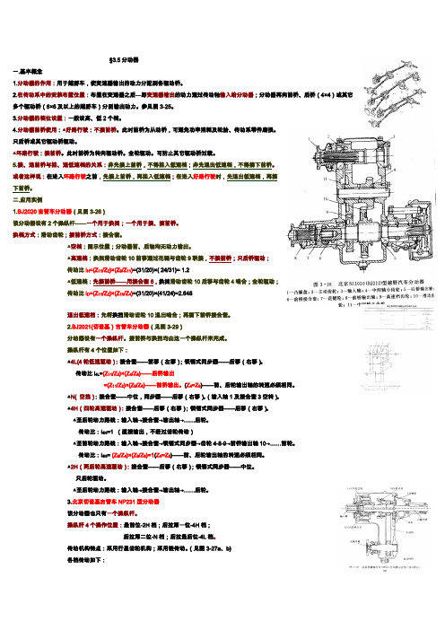
二.应用实例1.BJ2020吉普车分动器(见图3-26)该分动器设有2个操纵杆——一个用于换挡;一个用于接、摘前桥。
换档方式:滑动齿轮;接前桥方式:接合套。
▲空档:图示位置;分动器前、后轴均无动力输出。
▲高速档:换挡滑动齿轮10前移通过花键与齿轮9联接,不接前桥;只后桥驱动;传动比i H=(Z11/Z2)×(Z9/Z11)=(31/20)×( 24/31)= 1.2▲低速档:先接前桥——用接合套6,换挡滑动齿轮10后移与齿轮4啮合;全轮驱动;传动比i D=(Z11/Z2)×(Z10/Z4)=(31/20)×(41/24)=2.648退出低速档:先将换挡滑动齿轮10退出啮合;再摘下前桥接合套。
2.BJ2021(切诺基)吉普车分动器(见图3-29)分动器设有一个操纵杆。
接前桥与换挡均由这一个操纵杆来完成。
操纵杆有4个位置如下:▲4L(4轮低速驱动):接合套——前移(左移);锁销式同步器——后移(右移)。
传动比i4L=(Z11/Z2)×(Z4/Z8)——后桥输出=(Z11/Z2)×(Z9/Z8)——前桥输出。
汽车分动器设计说明书

壳体加工工艺………………………………………………………….....39
拨叉加工工艺………………………………………………………….....39
齿轮加工工艺………………………………………………………….....41
轴的加工工艺………………………………………………………….....41
总成的装配…………………………………………………………….....42
啮合套的设计计算………………………………………………………..17
5分动器结构元件……………………………………………………………....18
齿轮……………………………………………………………………......18
轴及相关零件……………………………………………………………..18
分动器壳体……………………………………………………………......28
1 绪论..…………………………………………………………................................1
分动器简介..………………………………………………………………..1
毕业设计任务及要求.....……………………………………………………1
分动器的公用和设计要求....………………………………………………2
利用前后轮的转速差使当后轮滑转时自动接上前驱动桥,倒档时则用另一超越离合器工作。
按使用性能可分为:
分动器
>> 第10章变速器与分动器10.5 分动器一、分动器的功用1.将变速器输出的动力分配到各驱动桥:越野汽车因多轴驱动而装有分动器,因而需要将动力分配到各驱动桥。
2.兼起副变速器的作用:目前大多数越野汽车装用两档分动器,兼起副变速器的作用。
3.降速增扭:两档分动器的低速档可起降速增扭作用。
二、分动器的构造分动器由齿轮传动机构和操纵机构两部分组成。
(一)齿轮传动机构分动器的齿轮传动机构是由若干齿轮、轴和壳体等零件组成。
有的还装有同步器。
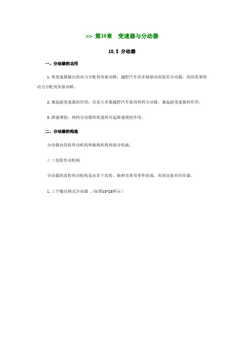
l.三个输出轴式分动器 ,(如图10-25所示)(点击图片可放大)图10-25 三个输出轴式分离器1-输出轴;2-分离器;3、5、9、10、13、15-齿轮;4-换档结合套;7-分动器盖;8-后桥出轴;11-中间轴;12-中桥输出轴;14-换档拨叉;16-前桥结合套;17-前桥输出轴1)结构:图10-26为三轴式两档分动器的结构简图。
分动器单独安装在车架上,其输入轴l 用凸缘通过万向传动装置与变速器第二轴连接。
输出轴8、12、17分别经万向传动装置通往后、中、前驱动桥。
分动器的常啮合齿轮均为斜齿轮,轴的支承多采用锥轴承。
轴l前端支承在壳体上,后端支承在与轴9制成一体的齿轮6的中心孔内。
齿轮5与轴l制成一体。
齿轮3、10、13分别用半圆键连接在轴l、11、13上。
齿轮、15和9之间装有换档接合套4。
前桥输出轴17后端装有接合套16,其右移使轴17和轴12相连接,即前桥驱动。
图10-26 三个输出轴式分动器的结构l-输入轴;2-分动器壳;3、5、6、9、10、13、15-齿轮;4-换档接合套;8-后桥输出轴;11-中间轴;12-中桥输出轴;16-前桥接合套;17-前桥输出轴2)工作情况:(1)空档:图10-26所示的是分动器空档位置。
(2)高速档:将接合套4左移与齿轮15的齿圈接合时为高速档,动力→输入轴l→齿轮3→15→接合套4→中间轴11→齿轮10,再分别经齿轮6、13传到输出轴8和12。
CR-V轿车分动器设计
摘要汽车若在冰雪路面或无路的情况下行驶时,就要求增加驱动车轮的数目,以充分利用汽车的重量来增加车轮与道路间的附着力。
分动器的主要功用是将发动机输出的动力分配到各驱动桥,并且进一步增大扭矩;其另一个功用是兼起副变速器的作用。
分动器也是一个齿轮传动系统,它单独固定在车架上,其输入轴与分动器的输出轴用万向传动装置连接,分动器的输出轴有若干根,分别经万向传动装置与各驱动桥相连。
本设计根据匹配车型的使用条件和车辆参数选择分动器的结构形式,并按照分动器总成的设计步骤和要求,对其主要零部件,如齿轮、轴进行了相关的设计工作和校核工作。
并根据汽车设计、汽车理论、机械设计、机械设计课程等参考资料提供的相关知识,对计算出的分动器具体参数进行检验,并论证设计的合理性。
最终,用AutoCAD软件完成分动器二维装配图和零件图的绘制。
关键词:分动器;分时;中心距;齿轮;轴;结合套ABSTRACTIf car drive in snow and ice road or no way under the condition of the road, it’s to ask for an increase in the number of driver wheels,To take full advantage of the weight of the car to increase the wheels and the adhesion between road,The main function is to thansfer engine output power distribution to the driving axle, and further increase torque, the other a function is and the deputy variable speed.Thansfer is also a gear transmission system, it alone in frames, the fixed input shaft and thansfer output shaft with universal transmission devices connected, thansfer output shaft several root, the universal respectively with each drive transmission device connected.This design according to the conditions of use and matching model vehicle parameter selection of structure form, and thansfer according to the design procedures of the assembly thansfer and requirement, for its main parts, such as gear, the shaft related design work and check work. And according to the car design, car theory, mechanical design, mechanical design courses provide reference information for the relevant knowledge, calculated from the concrete parameters for inspection, thansfer and demonstrates the rationality of the design. Finally, with AutoCAD software thansfer 2 d assembly drawings and component drawing.Key words:Thansfer; points; center distance;Gear;Axis;Meshing sets目录摘要 (Ⅰ)Abstract (Ⅱ)第1章绪论 (1)1.1 选题背景 (3)1.2 分动器简介 (3)1.2.1 分动器的类型 (6)1.2.2分动器的构造和原理 (4)1.3 分动器的设计思想 (4)1.4 本设计主要完成的内容 (5)第2章分动器设计的总体方案 (6)2.1 分动器结构方案的选择 (6)2.1.1 传动机构布置方案分析 (6)2.1.2 零部件结构方案分析 (6)2.2设计依据 (8)2.2.1 挡数的确定 (9)2.2.2 传动比的确定 (9)2.2.3 分动器中心距的确定 (11)2.3 本章小结 (11)第3章主要零部件的设计及计算 (13)3.1 齿轮的设计及校核 (13)3.1.1 齿轮参数确定及高低挡齿轮齿数分配 (13)3.1.2 轮齿强度计算 (15)3.1.3 分动器齿轮的材料及热处理 (17)3.2 轴的设计及校核 (18)3.2.1 轴的失效形式及设计准则 (18)3.2.2 轴的设计 (18)3.2.3 轴的校核 (19)3.3 轴承的选用及校核 (22)3.3.1 分动器轴承型式的选择 (22)3.3.2 轴承的校核 (22)3.3.3 轴承的润滑和密封 (24)3.4本章小结 (24)第4章分动器其他零件及机构的设计 (25)4.1 同步器的设计及计算 (25)4.2 惯性式同步器 (25)4.2.1锁环式同步器的结构 (25)4.2.2锁环式同步器的工作原理 (25)4.2.3锁环式同步器主要尺寸的确定 (27)4.3主要参数的确定 (28)4.3.1摩擦因数f (28)4.3.2同步环主要尺寸的确定 (28)4.3.3锁止角 (29)4.3.4同步时间 (30)4.3.5转动惯量的计算 (30)4.4本章小结 (30)结论 (31)参考文献 (32)致谢 (33)附录 (34)第1章绪论1.1 选题背景在当今飞速发展的社会现况下,人们对生活用品的需求上不断的最求便捷和完美。
长城哈弗H3越野车分动器设计[答辩毕业论文资料].doc
![长城哈弗H3越野车分动器设计[答辩毕业论文资料].doc](https://img.taocdn.com/s3/m/0e65535de55c3b3567ec102de2bd960590c6d973.png)
在多轴驱动的汽车上,为了将变速器输出的东路分配到各个驱动桥,均装有分动器。
分动器的棊本结构也是一个齿轮传动系统。
其输入轴直接或通过万向传动装置与变速器第二轴相连,其输出轴则有若干个,分别经万向传动装置与各驱动桥连接。
为增加传动系的最大传动比及档数,A前绝大多数越野车都装有两档分动器,使之兼起副变速器的作用。
木课题针对哈弗H3越野汽车的分动器进行设计,木文首先分析了分动器的结构原理以及对比国内外分动器研究成果。
接着提出满足哈弗H3越野汽车功能的分动器设计方案,哈弗H3越野汽车冇一个输入轴两个输出轴,输入轴通过万向轴与变速器输出轴连接,两个输出轴分别与前后桥驱动轴连接起到动力分配和减速增矩的作用。
本文对分动器组成的齿轮、轴、同步器分别进行了详细设计,对今后的分动器设计具有很好的指导意义。
关键字:分动器齿轮轴同步器AbstractIn the multi-axis drive car,in order to assign to each East transmission output drive axle, both equipped with a splitter . The basic structure of the actuator is a gear transmission . The input shaft directly or via a universal drive shaft is connected to a second transmission means and,there arc a number of the output shaft,respectively,through a universal drive means connected to each drive axle . To increase the maximum transmission ratio of the drive train and the number of files,the vast majority of off-road vehicles are equipped with two tranches actuator,make and play the role of deputy transmission.The topic for the Hover H3 sport utility vehicles splitter design, this paper analyzes the principle and comparative research abroad splitter structure of the actuator . Then Hover H3 off-road vehicles to meet the proposed functions of actuator design,Hover H3 off-road vehicle has an input shaft two output shafts,input shaft is connected through a cardan shaft transmission output shaft and two output shafts and axle shaft,respectively,power distribution and connection to play the role of the deceleration torque-up • Gears,shafts,synchronizer actuator consisting of this paper were carried out detailed design for the future design of the actuator has a good guide .Keywords: Splitter Gear Shaft Synchronizer目录餓 (4)1.1分动器简介 (4)1.2课题研究背景及意义 (4)1.3国内外相关研究现况 (5)1.4设计要求 (6)1.4.1设计参数 (6)1.4.2设计基本要求 (6)第二章总体设计 (7)2.1分动器结构与工作原理分析 (7)2.2传动方案 (8)2.3齿轮的布置 (8)2.4换挡结构形式的选择 (9)2.5挡数及传动比的确定 (10)2.6中心距A确定 (11)第三章齿轮的设计及校核 (13)3.1基本参数的选择 (13)3.1.1模数的确定 (13)3.1.2压力角 (13)3.1.3螺旋角的确定 (13)3.1.4 齿宽 (13)3.1.5齿顶高系数 (14)3.2各档齿轮齿数的确定 (14)3.2.1低速档齿轮副齿数的确定 (14)3.2.2对中心距进行修正 (14)3.2.3确定其他齿轮的齿数 (15)3.3齿轮的变位 (15)3.4齿轮的校核 (17)3.4.1计算扭矩T的确定 (17)3.4.2轮齿的弯曲应力 (19)3.4.3轮齿接触应力 (22)第四章轴及附件的设计 (24)4.1轴的结构形式 (24)4.2轴的尺寸初选 (24)4.3轴的结构设计 (25)4.4轴的强度计算 (26)4.4.1轴的受力计算 (26)4.4.2轴的刚度计算 (26)4.4.3轴的强度计算 (28)4.5同步器设计 (32)4.5.1同步器的功用及分类 (32)4.5.2同步器主要尺寸的确定 (32)4.5.3主要参数的确定 (33)4.5.3啮合套的设计 (34)4.6箱体的设计 (34)@ 论 (34)參考越 (36)至文i射 (37)第一章绪论1.1分动器简介装于多桥驱动汽车的变速器后,用于传递和分配动力至各驱动桥,兼作副变速器之用。
分动器设计说明书11
中华人民共和国教育部东北林业大学毕业设计设计题目:分时四驱分动器设计学生:指导教师:学院:交通学院专业班级:交通运输类(车辆工程)2005级7班2009年6月东北林业大学毕业设计任务书设计题目分时四驱分动器设计指导教师李宏刚讲师专业交通运输类(车辆工程)2005级7班学生管延才2009年1月3日分时四驱分动器设计摘要本设计主要根据现代狮跑2.0L手动四驱SUV汽车的相关技术参数进行分动器的设计。
根据匹配车型的使用条件和车辆参数选择分动器的结构形式,并按照分动器系统的设计步骤和要求,具体进行了分动器轴、齿轮等零部件的相关设计工作和校核工作,最后绘制了二维图纸。
关键词:分动器;分时;设计Design Of Time Four-wheel ActuatorAbstractThe design is based mainly on the modern lion run manually 2.0L four-wheel-drive SUV vehicle-related parameters at the design of the actuator. In accordance with the conditions of vehicles and vehicle parameters, in accordance with the actuator sub-system design steps and requirements, mainly related to design work, including the sub-center distance of actuators, bevel gear and other parameters. And a sub-axis actuators, gears and other parts of the design and verification of the relevant work.Keywords: Sub-actuator; center distance; design目录摘要Abstract1 绪论 (1)1.1分动器简介 (1)1.2 分动器的构造及原理 (1)1.3 分动器的类型 (2)2 分动器主要参数的选择 (4)2.1档数及传动比 (4)2.2 中心距的确定 (5)2.3 齿轮参数的确定 (5)2.4高低档传动比及其齿数的确定 (6)3 分动器齿轮强度计算及材料选择 (8)3.1 齿轮失效形式与原因 (8)3.2 齿轮强度计算与校核 (8)4 分动器轴的计算与校核 (10)4.1 分动器轴的失效形式 (10)4.2 分动器轴的初选 (10)4.3 分动器轴承的选择 (11)4.4 键的选择与计算 (11)5 同步器 (13)5.1 同步器的结构类型 (13)5.2锁环式同步器的工作原理 (13)5.3惯性锁止式同步器的主要结构参数 (15)6总结 (17)参考文献致谢分时四驱分动器设计1 绪论1.1分动器简介装于多桥驱动汽车的变速器后,用于传递和分配动力至各驱动桥,兼作副变速器之用。
- 1、下载文档前请自行甄别文档内容的完整性,平台不提供额外的编辑、内容补充、找答案等附加服务。
- 2、"仅部分预览"的文档,不可在线预览部分如存在完整性等问题,可反馈申请退款(可完整预览的文档不适用该条件!)。
- 3、如文档侵犯您的权益,请联系客服反馈,我们会尽快为您处理(人工客服工作时间:9:00-18:30)。
3 分动器主要参数的选择……………………………………………………....8
传动比分配……………………………………………………………........8
中心距A…………………………………………………………………....8
4 分动器齿轮参数的确定……………………………………………………..10
模数………………………………………………………………………..10
压力角……………………………………………………………………..10
螺旋角……………………………………………………………………..10
齿宽………………………………………………………………………..11
各档齿轮齿数的分配……………………………………………………..11
Process some of the major components of typical processes are analyzed to determine the types of parts materials, developed a process card.
Key words:Actuator sub-terrain vehicle;Gear;Axis;Meshing sets;Shell Technology
啮合套的设计计算………………………………………………………..17
5分动器结构元件……………………………………………………………....18
齿轮……………………………………………………………………......18
轴及相关零件……………………………………………………………..18
分动器壳体……………………………………………………………......28
This article describes the sub-terrain vehicle actuator design calculations, design and technology is divided into two major parts. The design of some of the more detailed description of the sub-actuator design process, select the structure of the program, the main parameters, gear design, shaft design, calculation verification, the design of other structural components.
分动器的构造及原理..……..………………………………………………3
2 分动器结构方案的选择..………………………………………………...…...6
传动方案….…………………………………………………………...........6
齿轮的安排….……………………………………………………...............6
本文主要说明了越野车分动器的设计计算过程,主要分为设计和工艺两大部分。设计部分较详细的叙述了分动器的设计过程,选择结构方案、主要参数、齿轮设计、轴设计、计算校核、其他结构部件的设计。
工艺部分主要对典型零件的工艺过Байду номын сангаас进行了分析,确定了各类零件的材料,制定了工艺过程卡片。
关键词:越野车分动器; 齿轮; 轴;啮合套;壳体工艺
EQ1090-based design of automotive
sub-actuator
Abstract:The need for off-road vehicles often have no bad roads and traffic situations, especially military vehicles driving conditions even worse. This requires increasing the number of motor vehicle wheel, therefore, off-road vehicle use multi-axis drive.
6零件的校核…………………………………………………………………....30
Sub-actuator function is the allocation of transmission power output to the drive axle, and further increase the torque. Actuator is also a sub-gear drive system, which separately fixed on the vehicle chassis, the transmission input shaft and output shaft gear connected with universal joints, sub-actuator output shaft of a number of roots, respectively, by the universal gear with the bridge driver.
1 绪论..…………………………………………………………................................1
分动器简介..………………………………………………………………..1
毕业设计任务及要求.....……………………………………………………1
分动器的公用和设计要求....………………………………………………2
EQ1090型汽车分动器设计
摘要:越野车需要经常在坏路和无路情况下行驶,尤其是军用汽车的行驶条件更为恶劣。这就要求增加汽车驱动轮的数目,因此,越野车都采用多轴驱动。
分动器的功用就是将分动器输出的动力分配到各驱动桥,并且进一步增大扭矩。分动器也是一个齿轮传动系统,它单独固定在车架上,其输入轴与分动器的输出轴用万向传动装置连接,分动器的输出轴有若干根,分别经万向传动装置与各驱动桥相连。