GASCAT-调压阀手册
调压撬在天然气配输站中的应用分析
调压撬在天然气配输站中的应用分析主要是通过对中国石油西气东输长宁输气分公司银川压气站所使用的博斯特撬装压力控制系统的结构特点、特性参数、主要部件、运行方法、维修保养、故障处理等内容进行介绍分析。
达到對轴流式调压系统的原理和性能有更深的了解,从而更好地保证调压装置和供气系统在最佳状态下工作。
标签:安全切断阀监控调压阀流量调节阀中国石油西气东输长宁输气分公司银川压气站兰银管道所使用的博斯特撬装压力控制系统是由安全切断阀、监控调压阀、电动调节阀按照从上游至下游的顺序,依次串联在一起的安全、监控式压力控制系统。
安全切断阀、监控调压阀、电动调节阀为相互独立的设备。
正常情况下,安全切断阀和监控调压阀处于全开位置,由电动调节阀对下游压力进行控制。
当电动调节阀出现故障,无法控制下游压力时,监控调压阀开始工作,以维持下游压力的安全范围。
若监控调压阀也出现故障,不能控制下游压力时,安全切断阀则自动切断气源,以保证下游管道和设备的安全。
(如图1)1 安全切断阀目前,银川压气站兰银管道的三路撬装压力控制系统所使用的安全切断阀均为GASCAT公司GIPS-H系列产品。
型号:GIPS-H公称直径:DN200压力等级:CLASS600安全切断阀的工作原理:从下游(出口)管道上取出信号压力,并将该信号压力与设定压力进行比较,当下游气体压力超过安全切断阀的设定压力时,安全切断阀会迅速关闭。
关闭特点:依靠管道中的高压气体的自身压力作用在阀芯上。
切断阀的信号管为不锈钢。
安全切断阀在正常工作状态下为常开,一旦系统的压力达到设定值的上限或下限,它将自动切断供气管路。
自动切断后它不能自动打开,只能就地手动打开。
安全切断阀能通过调整单元或更换弹簧及其它部件(不必拆卸阀体)快捷、方便地改变安全切断阀的设定值。
用于现场改变设定值的调整单元具有保护措施,设定值设定后能锁定,可避免由于人为误操作造成压力控制系统异常工作。
安全切断阀在正常工作时长期处于全开状态,驱动阀门关断的驱动部件有稳定的保护措施,对于管道正常工作所产生的振动不会引起驱动部件的松懈或动作,从而导致安全切断阀产生误动作。
Festo VEAA比例调压阀操作手册说明书
原版操作手册的译本1适用文件有关产品的所有可用文件 è /pk。
用户文件名称,型号目录H 导轨安装件,VAME-P7-T 装配说明书安装板,VAME-P...-Y装配说明书气路条,VABM-P6-15.../-P7-18...装配说明书Tab. 1 产品文件2安全2.1安全注意事项–仅在原装状态下使用产品,请勿擅自进行改动。
–请仅在技术状态完好的情况下使用本产品。
–注意使用地的环境条件。
–装配、安装和维修保养工作:关闭电源,确保不会重新启动。
2.2按规定使用按照规定,比例压力阀用于根据给定的设定点值按比例调节压力。
本产品设计用于工业领域。
2.3专业人员的资质仅允许由具备资质的专业人员进行安装、调试、保养及拆卸。
专业人员必须掌握电气和气动控制系统安装的专业知识。
3详细信息–附件 è /catalogue 。
4服务若有技术问题,请联系 Festo 公司在您所在地的联系人è 。
5产品概览5.1功能原理其所配备的集成式压力传感器可感测到工作接口的压力,并将其与设定点值进行比较。
在实际值和设定点值之间存在偏差时,阀将进行调节,直到输出压力达到设定点值。
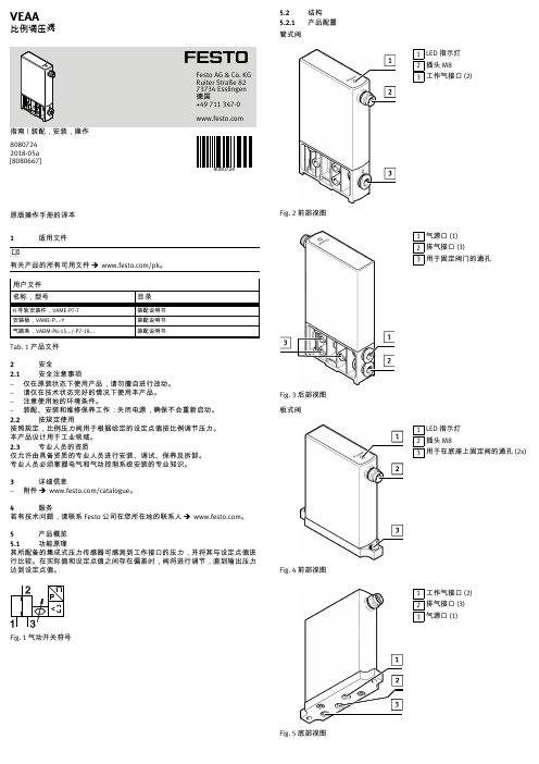
Fig. 1 气动开关符号5.2结构5.2.1产品配置管式阀1LED 指示灯2插头 M83工作气接口 (2)Fig. 2前部视图1气源口 (1)2排气接口 (3)3用于固定阀门的通孔Fig. 3 后部视图板式阀1LED 指示灯2插头 M83用于在底座上固定阀的通孔 (2x)Fig. 4 前部视图1工作气接口 (2)2排气接口 (3)3气源口 (1)Fig. 5 底部视图8080724VEAA比例调压阀80807242018-05a [8080667]Festo AG & Co. KG Ruiter Straße 82 73734 Esslingen 德国+49 711 347-0 5.2.2产品派生型特性型号代码说明基本功能VEAA 压电式比例调压阀L 管式阀阀类型B 板式阀阀功能3三位三通阀,常闭D20 … 2 bar D90 … 6 bar 压力范围D110 … 10 bar F 法兰/底座气接口Q4快插接头 4 mm V1电压型 0 … 10 V 额定值输入和实际值输出A4电流型 4 … 20 mA 额定工作电压124 V DC 电接口R1插头 M8,4 针Tab. 2 产品派生型6运输和存放–在干燥、防紫外线、防腐蚀的环境中存放本产品。
施瓦格洛克 微调阀-S,M,L,31系列产品手册说明书

S, M, L, and 31 Series■Straight-pattern flow coefficients (C v) from 0.004 to 0.16■ Low- and high-pressure service■Repeatable vernier handles available■Brass and 316 stainless steel materials2 Needle and Metering ValvesT U B E F I T T I N G SP I P E , W E L D , V C R , V C O F I T T I N G SS T A N D A R D T U B I N GM O D U L A R S Y S T E M DH O S E / F L E X I B L E T U B I N GB E L L O W S , D I A P H R A G M V A L V E SB A L L & P L U G V A L V E S31C H E C K & R E L I E F V A L V E SR E G U L A T O R S & F I L T E R S I N S T R U M E N T M A N I F O L D S Y S T E M SM E A S U R E M E N T D E V I C E SR E F E R E N C E SM E D I U M - H I G H - P R E S S U R ELock screw “locks in” flowsettings (knurled andslotted handles)Guide O-ring enhances stemalignment (S series only)Tapered stem tip accurately controls gas and liquid flow ratesStem threads are isolated from system fluidHandle stop helps prevent damage to stem and orifice Stem O-ring contains system fluid➀ D ownstream pressure 500 psig (34.4 bar) max when valve requiresadjustment at pressure due to strength limitations of the fine-pitch threads and high operating torque.➁ S tainless steel L series valves are not recommended for shutoff in vacuum or gas service, or for repetitive shutoff in liquid service.S series valve shown.High-Pressure Valves (31 Series)■ Flow coefficient of 0.04; orifice of 0.062 in. (1.6 mm) ■ 316 SS bar stock body ■ Straight and angle patterns ■ Metal-to-metal shutoff ■ 2° stem taper (included angle)■ P anel mounting ■ Round phenolic handle■ Swagelok tube fitting and female NPT end connectionsPressure-Temperature RatingsRatings based on optional Grafoil ® packing.Ratings limited to 450°F (232°C) at 3435 psig (236 bar) with standard PTFE packing.Packing nut permits simpleexternal adjustment Packingfully contained by 316 SS glands to prevent extrusion 440C SSregulating stemhardened for enhanced service lifeaccurately controls gas and liquid flow ratesMetal-to-metal shutoff31 SeriesMetering Valves—S, M, L, and 31 Series 3Materials of ConstructionLow-Pressure Valves (S, M, and L Series)234568791a 1b2234488759913456891027High-Pressure Valves (31 Series)TestingEvery Swagelok S, M, and L series metering valve is factory tested with nitrogen at 1000 psig (69 bar). Shell testing is performed to a requirement of no detectable leakage with a liquid leak detector.Every Swagelok L series metering valve is tested for bubble-tight seat shutoff at 100 psig (6.8 bar) differential pressure.Every Swagelok 31 series needle valve is factory tested with nitrogen at 1000 psig (69 bar). Seats have a maximum allowable leak rate of 0.1 std cm 3/min.S Series M SeriesL SeriesWetted components listed in italics.➀ Anaerobic-type adhesive.➁ Straight and double-pattern M series valves.➂ A ngle and cross-pattern M series valves do not contain a body seal.1a Cleaning and PackagingSwagelok metering valves with VCR end connections areprocessed in accordance with Swagelok Special Cleaning and Packaging (SC-11) catalog , MS-06-63, to ensure compliance with product cleanliness requirements stated in ASTM G93 Level C .Swagelok metering valves with other end connections are processed in accordance with Swagelok Standard Cleaning and Packaging (SC-10) catalog, MS-06-62, special cleaning and packaging are available as an option.4 Needle and Metering ValvesM series valve shown.S series—0.16 in. (4.1 mm) maximum panel thickness.M and L series—0.13 in. (3.3 mm) maximum panel thickness.31 SeriesFor angle-pattern 31 series valves, add -A to the ordering number.Example: SS-31RS4-AMaximum Flow—0.16 C vMaximum Flow—0.04 C vStraight PatternMetering Valves—S, M, L, and 31 Series 5DimensionsDimensions, in inches (millimeters), arefor reference only and are subject to change.Angle PatternAngle Pattern6 Needle and Metering ValvesTUBEFITTINGSPIPE,WELD,VCR,VCOFITTINGSSTANDARDTUBINGMODULARSYSTEMDHOSE/FLEXIBLETUBINGBELLOWS,DIAPHRAGMVALVESBALL&PLUGVALVES31CHECK&RELIEFVALVESREGULATORS&FILTERSINSTRUMENTMANIFOLDSYSTEMSMEASUREMENTDEVICESREFERENCESMEDIUM-HIGH-PRESSUREDouble PatternS and M Series■ Inlet valve handle can be set andlocked at desired maximum flow.■ Outlet valve handle can be used forfine flow control up to the presetmaximum of the inlet valve.S series valve shown.Cross PatternS and M Series■ Fluid flows between side portsaround stem in any stem position.■ Flow through branch port can bemetered in both directions.Ordering Information and DimensionsSelect an ordering number. For brass valves, replace SS with B.Example: B-SS2-XDimensions are for reference only and are subject to change.M series valve shown.Options and AccessoriesMetering Valves—S, M, L, and 31 Series 7Colored Handles31 SeriesBlack phenolic handles are standard. To order colored phenolic handles, add a handle color designator to the ordering number.Example: SS-31RS4-BL Handle KitsHandle kits contain handle, brass insert, and instructions.To order a black phenolic handle, use kit ordering number PH-5K -14K-BK.For colored phenolic handles, replace -BK in the kit ordering number with a handle color designator.Example: PH-5K-14K -BLAdjustable-Torque HandleVernier HandleS, M, and L Series■ Enhances control for setting flows.■ Features PTFE packing and two top-mounted torque adjustment screws.■ Is available in stainless steel materialon stainless steel valves and in chrome-plated brass on brass valves, as standard.To order, add -OH to the ordering number.Example: SS-SS1-OHAdjustable-Torque Handle Kits Kits contain all parts necessary to add an adjustable-torque handle to an existing valve.Slotted HandleS and M Series■ Helps ensure repeatable flow adjustments.■ Provides readings accurate to1/25 turn.To order, add -VH to an S series ordering number or -MH to an M or L series ordering number.Examples:S S-SS1-VHSS-2MG -MH Vernier Handle KitsKits contain all parts necessary to add a vernier handle to an existing valve.■ Allows flow setting adjustment with ascrewdriver.■ Is for use in installations wherehandle is not easily accessible.■ Is available in stainless steel materialon stainless steel valves and in chrome-plated brass on brass valves, as standard.■ Allows valve to be panel mountedwithout removing handle.To order, add -SL to the ordering number.Example: SS-SS1-SLDimensions, in inches (millimeters), are for reference only and are subject to change.1.82 (46.2)open(21.0)A openM series valve shown.Slotted Handle KitsKits contain all parts necessary to add a slotted handle to an existing valve.1.42 (36.1)open(12.2)Options and Accessories8 Needle and Metering ValvesT U B E F I T T I N G SP I P E , W E L D , V C R , V C O F I T T I N G SS T A N D A R D T U B I N GM O D U L A R S Y S T E M DH O S E / F L E X I B L E T U B I N GB E L L O W S , D I A P H R A G M V A L V E SB A L L & P L U G V A L V E S31C H E C K & R E L I E F V A L V E SR E G U L A T O R S & F I L T E R SI N S T R U M E N T M A N I F O L D S Y S T E M SM E A S U R E M E N T D E V I C E S R E F E R E N C E SM E D I U M - H I G H - P R E S S U R E High-Temperature Stem Packing Material31 SeriesGrafoil packing extends the temperature rating to 850°F (454°C) and requires fluorinated tungsten disulfide-based lubricant. To order, add -G to the ordering number.Example: SS-31RS4-G Stem Packing KitsPTFE and Grafoil packing kits are available. Kits include packing, lubricant, and instructions. Select a kit ordering number.Special Cleaning and Packaging (SC-11)All SeriesSwagelok metering valves with VCR end connections are processed in accordance with Swagelok Special Cleaning and Packaging (SC-11) catalog , MS-06-63, to ensurecompliance with product cleanliness requirements stated in ASTM G93 Level C .To order special cleaning and packaging for metering valves with other end connections, add -SC11 to the valve ordering number.Example: SS-SS1-SC11Oxygen Service HazardsFor more information about hazards and risks of oxygen-enriched systems, refer to Swagelok Oxygen System Safety technical report, MS-06-13.MS-01-142, RevM, November 2021Options and Accessories• A packing adjustment may be required periodicallyto increase service life and to prevent leakage.• To increase service life, ensure proper valveperformance, and prevent leakage, apply only as much torque as is required to achieve positive shutoff in L and 31 series valves that are rated for shutoff service.IntroductionSince 1947, Swagelok has designed, developed, and manufactured high-quality, general-purpose and specialty fluid system products to meet the evolving needs of global industries. Our focus is on understanding our customers’ needs, finding timely solutions, and adding value with our products and services.We are pleased to provide this global edition of the book-bound Swagelok Product Catalog, which compiles more than 100 separate product catalogs, technical bulletins, and reference documents into one convenient, easy-to-use volume. Each product catalog is up to date at the time of printing, with its revision number shown on the last page of the individual catalog. Subsequent revisions will supersede the printed version and will be posted on the Swagelok website and in the Swagelok electronic Desktop Technical Reference (eDTR) tool.For more information, visit your Swagelok website or contact your authorized Swagelok sales and service representative.Safe Product SelectionWhen selecting a product, the total system design must be considered to ensure safe, trouble-free performance. Function, material compatibility, adequate ratings,proper installation, operation, and maintenance are the responsibilities of the system designer and user.Warranty InformationSwagelok products are backed by The Swagelok Limited Life-time Warranty. For a copy, visit or contact your authorized Swagelok representative.Not all trademarks listed below apply to this catalog. Swagelok, Cajon, Ferrule-Pak, Goop, Hinging-Colleting,IGC, Kenmac, Micro-Fit, Nupro, Snoop, Sno-Trik, SWAK, VCO, VCR, Ultra-Torr, Whitey—TM Swagelok Company 15-7 PH—TM AK Steel Corp.AccuTrak, Beacon, Westlock—TM Tyco International Services Aflas—TM Asahi Glass Co., Ltd.ASCO, El-O-Matic—TM Emerson AutoCAD—TM Autodesk, Inc.CSA—TM Canadian Standards AssociationCrastin, DuPont, Kalrez, Krytox, Teflon, Viton—TM E.I. duPont Nemours and Company DeviceNet—TM ODVADyneon, Elgiloy, TFM—TM Dyneon Elgiloy—TM Elgiloy Specialty Metals FM —TM FM GlobalGrafoil—TM GrafTech International Holdings, Inc.Honeywell, MICRO SWITCH—TM Honeywell MAC—TM MAC ValvesMicrosoft, Windows—TM Microsoft Corp.NACE—TM NACE InternationalPH 15-7 Mo, 17-7 PH—TM AK Steel Corp picofast—Hans Turck KGPillar—TM Nippon Pillar Packing Company, Ltd.Raychem—TM Tyco Electronics Corp.Sandvik, SAF 2507—TM Sandvik AB Simriz—TM Freudenberg-NOKSolidWorks—TM SolidWorks Corporation UL—Underwriters Laboratories Inc.Xylan—TM Whitford Corporation © 2021 Swagelok Company。
各国的燃气调压器
各国的燃气调压器美国FISHER系列调压器有:EZR、MP、310A、630、627等系列调压器可广泛应用于城市门站、高中压区域调压站,EZR、1098、299型调压器可应用于中低压区域调压站及中型调压箱、133、299、REGAL2、REGAL3、S200、S300、系列调压器则大量在工业及公福用户调压站上所使用,REGAL2、R622、S100、B系列调压器同时也供应于居民用户调压站。
FISHER调压器性能稳定,调压范围较广、分有带切断与不带切断、部分调压器带有滤网保护,可作监控连接、保证安全、安装省力、经济实惠,性价比高。
意大利TATANINI系列调压器有:FL系列带指挥器轴流式调压器、R系列弹簧负载式调压器、MN及MBN系列带切断监控式调压器、RP系列、MR系列全固定弹簧负载式调压器、RP/10系列气动式调压器等等。
美国AMCO系列调压器/皮膜表有:2003、1800PFM系列、AFV-50、AFV-80、AFV-100、RFV等轴流式系列调压器可广泛应用于城市门站、高中压区域调压站,1200系列、1813B2系列、1800系列、1800CPB2型调压器可应用于中低压区域调压站及中型调压箱,美国AMCO 产品当中还包括ZSC系列指挥器。
AMCO皮膜表有AL-425、AL-630等系列,压力为中压,适用于工业及酒店。
AMCO调压器性能稳定,调压范围较广、分有带切断与不带切断、部分调压器带有滤网保护,可作监控连接、保证安全、安装省力、经济实惠,性价比高。
德国RMG系列调压器有:德国RMG集团公司始建于1908年,提供德国RMG调压器,如果需要欢迎来电联系至今已拥有7家下属公司,德国RMG集团公司是生产与燃气有关产品的专业公司,其产品包括:燃气输配用各种类型调压器,阀门,过滤器,安全切断阀,安全放散阀,流量计等。
自20世纪80年代开始,RMG公司的产品开始在中国使用,目前我司现货供应:RMG331,RMG320,RMG330,RMG342,RMG300,RMG219,RMG270,RMG512,RMG530等带切断与法兰接口式调压器。
Z3050QPF-E ZoneTight 三路压力调节阀说明书
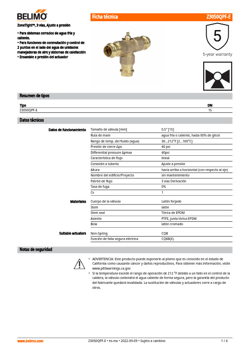
••ZoneTight™, 3 vías, Ajuste a presión• Para sistemas cerrados de agua fría y caliente.• Para funciones de conmutación y control de 2 puntos en el lado del agua de unidades manejadoras de aire y sistemas de calefacción • Ensamble a presión del actuadorResumen de tiposTipoDN Z3050QPF-E15Datos técnicosDatos de funcionamientoTamaño de válvula [mm]0.5" [15]Ruta de mamagua fría o caliente, hasta 60% de glicol Rango de temp. del fluido (agua)36...212°F [2...100°C]Presión de cierre ∆ps 40 psi Differential pressure Δpmax 40psi Característica de flujo linealConexión a tubería Ajuste a presiónAlturahacia arriba a horizontal (con respecto al eje)Nombre del edificio/Proyecto sin mantenimiento Patrón de flujo 3 vías Derivación Tasa de fuga 0%Cv1MaterialesCuerpo de la válvula Latón forjado Stem latónStem seal Tórica de EPDM Asiento PTFE, junta tórica EPDM Bolalatón cromado Suitable actuatorsNon-SpringCQB Función de falla segura eléctricaCQKB(X)Notas de seguridadADVERTENCIA: Este producto puede exponerlo al plomo que es conocido en el estado de California como causante cáncer y daños reproductivos. Para obtener más información, visite Si la temperatura excede el rango de operación de 212 °F debido a un fallo en el control de la caldera, la válvula contendrá el agua caliente de forma segura, pero la garantía del producto del fabricante quedará invalidada. La sustitución de válvulas y actuadores corre a cargo de otros.AplicaciónModo de operación Montaje directo y sencilloPosiciones de instalación recomendadasRequisitos de calidad del aguaServicioCaracterísticas del productoLas válvulas de zona QCV son adecuadas para grandes edificios comerciales donde se desea un mayor cierre y la capacidad de cambiar el flujo. Las aplicaciones comunes incluyen ventiladores unitarios, unidades fan coil, serpentines de recalentamiento VAV, carcasas de tubos de aletas, paneles radiantes y serpentines de conductos. La válvula encaja en áreas de espacio restringido y se puede ensamblar sin el uso de herramientas.Detalles de flujo / montajeLa válvula de zona para conmutación se ajusta mediante un actuador giratorio. El actuador giratorio se controla mediante una señal de apertura/cierre.Montaje a presión sin necesidad de herramientas.El actuador puede montarse en la válvula mediante presión manual (Precaución: Únicamente pueden hacerse movimientos verticales). Las pestañas deben encajar en los agujeros de la brida.La orientación de montaje con respecto a la válvula puede seleccionarse en incrementos de 180°. (Es posible hacerlo dos veces)Notas de instalaciónLa válvula de bola se puede instalar de vertical a horizontal. La válvula de bola no puedeinstalarse en posición suspendida, es decir, con el vástago hacia abajo.Las válvulas Belimo son dispositivos de regulación. Para que las válvulas funcionencorrectamente a largo plazo, deben mantenerse libres de partículas (por ejemplo, cordones de soldadura durante los trabajos de instalación). Se recomienda la instalación de un filtro colador adecuado. No debe haber partículas de más de 0.04 "(1 mm).Las válvulas de bola y los actuadores giratorios no requieren mantenimiento.Antes de realizar cualquier trabajo de servicio en el dispositivo de control final, es esencial aislar el actuador giratorio de la fuente de alimentación (desconectando el cable eléctrico si es necesario). Todas las bombas en la parte del sistema de tuberías en cuestión también deben apagarse y las válvulas correderas adecuadas deben cerrarse (deje que todos los componentes se enfríen primero si es necesario y siempre reduzca la presión del sistema al nivel de presión ambiente).El sistema no debe volver a ponerse en servicio hasta que la válvula de bola y el actuador giratorio se hayan reensamblado correctamente de acuerdo con las instrucciones y la tubería haya sido rellenada por personal capacitado profesionalmente.Dirección del flujo Ajuste de flujoEl sentido del flujo es posible en ambas direcciones.Debe retirarse la pinza de tope en el actuador para obtener un ángulo de giro de 90°, necesariopara la funcionalidad de cambio de régimen.Retire la pinza de tope finalDibujos dimensionalesTipo DN Z3050QPF-E15A B C D E F4.9" [125] 4.2" [107]5,0" [127] 2.7" [69]0.9" [24]0,9" [24]A B C D E F4.9" [125] 4.2" [107]4,8" [122] 2.6" [65]0.9" [24]0,9" [24]On/Off, punto flotante, sin resorte de retorno,24 V• Tensión nominal AC/DC 24 V• Control On/Off (Encendido/Apagado), Punto flotante• Señal de salida (posición)Datos técnicosDatos eléctricosTensión nominal AC/DC 24 V Frecuencia nominal 50/60 HzRango de tensión nominalAC 19.2...28.8 V / DC 21.6...28.8 V Consumo de energía en funcionamiento 0.3 W Consumo energía en reposo 0.2 W Transformer sizing 0.6 VAConexión eléctrica Cable completo de 18 GA, 3 ft [1 m], con conector de conducto de 1/2"Protección de sobrecarga electrónica giro completo 0...90°Electrical Protectionlos actuadores tienen doble aislamiento Datos de funcionamientoÁngulo de giro90°Nota sobre el ángulo de giro ajustable con tope mecánico Tiempo de giro (motor)75 s / 90°Nivel de ruido, motor 35 dB(A)Indicador de posiciónindicadorDatos de seguridadFuente de suministro eléctrico UL Alimentación de clase 2Grado de protección IEC/EN IP40Grado de protección NEMA/UL NEMA 2RecintoUL Enclosure Type 2Listado de agenciascULus según UL60730-1A/-2-14, CAN/CSA E60730-1:02, CE según 2014/30/EU y 2014/35/EU; listado según UL 2043 - apto para su uso en cámaras de aire según la sección 300.22(c) del NEC y la sección 602.2 del IMC Norma de Calidad ISO 9001Temperatura ambiente2...40°CTemperatura de almacenamiento -40...176°F [-40...80°C]Humedad ambiente Máx. 95% RH, sin condensación Nombre del edificio/Proyectosin mantenimiento Peso Peso0.56 lb [0.20 kg]MaterialesMaterial de la carcasa UL94-5VAAplicaciónCaracterísticas del productoActuador ZoneTight de apertura/cierre/3 puntos sin función de protección a prueba de selección de la válvula debe hacerse de acuerdo con los parámetros de flujo y las especificaciones del sistema.El actuador se monta directamente en la válvula, sin necesidad de herramientas ni de un acoplamiento adicional.El actuador funciona en respuesta a 24 VAC/VDC. El ángulo de giro se puede ajustar con el tope mecánico integrado.Instalacion electricaNotas de instalaciónLos actuadores con cables de electrodomésticos están numerados.Los actuadores pueden conectarse en paralelo. El consumo eléctrico y la impedancia deentrada deben ser respetados.Los actuadores también pueden estar alimentados por DC 24V.Los actuadores con cable plenum no tienen números; en su lugar, utilizan códigos de colores.Cumple con los requisitos de cULus sin necesidad de una conexión a tierra eléctrica.¡Advertencia! ¡Componentes eléctricos con corriente!Durante la instalación, prueba, servicio y resolución de problemas de este producto, puede ser necesario trabajar con componentes eléctricos energizados. Haga que un electricista con licencia calificado u otra persona que haya recibido la capacitación adecuada en el manejo de componentes eléctricos activos realice estas tareas. No seguir todas las precauciones deseguridad eléctrica cuando se expone a componentes eléctricos energizados podría provocar la muerte o lesiones graves.Esquema de conexionadoTransformador AC 24 V On/Off AC 24 V / DC 24 VTransformador punto flotante AC 24 V。
安全阀及调压阀各项压力调整方法
安全阀和调压阀的压力调整方法如下:对于安全阀,开启压力的调整可以通过旋转调整螺杆,改变弹簧的预紧压缩量来进行。
具体的步骤包括:1. 拆去阀门罩帽,将锁紧螺母拧松。
2. 将进口压力升高,使阀门起跳一次。
3. 根据开启压力的情况,按顺时针或逆时针方向旋紧或旋松调整螺杆。
4. 调整到所需的开启压力后,将锁紧螺母拧紧,并装上罩帽。
在调整过程中,应注意以下要点:1. 当介质压力接近开启压力(达到开启压力的90%以上)时,不应旋转调整螺杆,以免阀瓣跟着旋转,损伤密封面。
2. 为保证开启压力值准确,调整时的介质条件,如介质种类、温度等,应尽可能接近实际工作条件。
介质种类改变或从液相变为气相时,开启压力常有所变化。
工作温度提高时,开启压力则有所降低。
故在常温下调整而用于高温时,应使常温下的整定压力值略高于要求的开启压力值。
3. 排放压力和回座压力的调整:开启压力调整好以后,若排放压力或回座压力不符合要求,可以利用阀座上的调节圈进行调整。
拧下调节圈固定螺钉,用工具拨动调节圈上的轮齿,使调节圈左右转动。
当调节圈向右作逆时针方向旋转时,其位置升高,排放压力和回座压力都将有所降低;反之,当调节圈向左作顺时针方向旋转时,其位置降低,排放压力和回座压力都将有所提高。
每一次调整后,都应将固定螺钉拧紧。
对于调压阀,其压力调整方法如下:1. 先关闭进口阀门,并拆去阀门两端的密封盖。
2. 松开锁紧螺母和调节螺母。
3. 用螺丝刀调节弹簧的预紧压缩量,以实现压力的调整。
4. 重新安装好调压阀的密封盖,并打开进口阀门。
请注意,安全阀和调压阀是特种设备,在进行相关操作时应严格遵守安全规程,并确保由专业人员进行操作。
燃气(过滤)调压器说明书
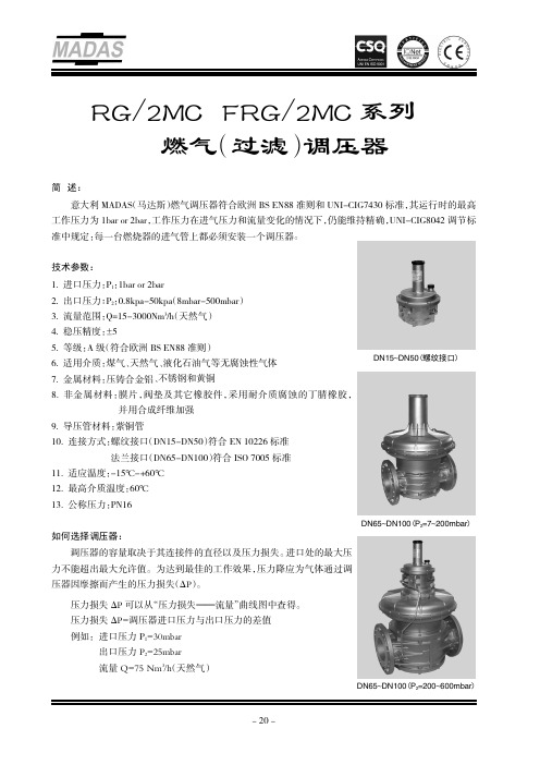
RG/2MC-FRG/2MC 系列燃气(过滤)调压器简述:意大利MADAS (马达斯)燃气调压器符合欧洲BS EN88准则和UNI-CIG7430标准,其运行时的最高工作压力为1bar or 2bar,工作压力在进气压力和流量变化的情况下,仍能维持精确,UNI-CIG8042调节标准中规定:每一台燃烧器的进气管上都必须安装一个调压器。
技术参数:1.进口压力:P 1:1bar or 2bar2.出口压力:P 2:0.8kpa-50kpa (8mbar-500mbar )3.流量范围:Q=15-3000Nm 3/h (天然气)4.稳压精度:±5%5.等级:A 级(符合欧洲BS EN88准则)6.适用介质:煤气、天然气、液化石油气等无腐蚀性气体7.金属材料:压铸合金铝、不锈钢和黄铜8.非金属材料:膜片,阀垫及其它橡胶件,采用耐介质腐蚀的丁腈橡胶,并用合成纤维加强9.导压管材料:紫铜管10.连接方式:螺纹接口(DN15-DN50)符合EN 10226标准法兰接口(DN65-DN100)符合ISO 7005标准11.适应温度:-15℃-+60℃12.最高介质温度:60℃13.公称压力:PN16如何选择调压器:调压器的容量取决于其连接件的直径以及压力损失。
进口处的最大压力不能超出最大允许值。
为达到最佳的工作效果,压力降应为气体通过调压器因摩擦而产生的压力损失(ΔP )。
压力损失ΔP 可以从“压力损失———流量”曲线图中查得。
压力损失ΔP=调压器进口压力与出口压力的差值例如:进口压力P 1=30mbar出口压力P 2=25mbar 流量Q=75Nm 3辕h (天然气)DN15~DN50(螺纹接口)DN65~DN100(P 2=7~200mbar )DN65~DN100(P 2=200~600mbar )选择合适的调压器,请按照如下步骤进行:1)计算压力损失ΔP=30-25=5mbar2)在纵轴上找到5mbar这一点,划一条水平线直到与从流量值引出的垂线相交于一点。
调压器操作指导书
调压器操作指导书1 主要内容及适用范围本指导书规定了燃气调压器运行的检查准备、操作程序和注意事项。
本指导书适用于中石油昆仑燃气有限公司调压器的投用、压力设置和系统运行切换等作业。
2 检查与准备2.1 操作人员要明确所操作燃气系统的压力等工艺参数设置要求。
2.2 检查所用工具、物品是否齐全,穿戴好工作服及劳保用品。
2.3 设定操作压力应遵循由高到低的原则,按步骤逐项进行。
一般设置压力顺序为:放散压力、切断压力、工作压力。
各用气场所可根据其用气特点要求和侧重保护方式的不同,调整各压力的设定值并结合工作实际调整压力设置。
3 操作程序3.1 调压器的投用3.1.1 确认调压器的进出口阀门已关闭。
3.1.2 测试切断阀的复位操作,确认切断阀设置压力正确并处于正常工作状态。
测试中切断阀或附加在调压器上的切断阀在执行了切断动作后须人工进行复位。
3.1.3 测试放散阀,确认放散阀设置压力正确并处于正常工作状态。
打开放散阀前边的控制阀门,使放散管路通畅,放散阀连接的放散管要符合安全要求。
3.1.4 缓慢开启进口阀门,并观察上游压力表是否在允许的压力范围,为避免出口压力表在送气时超量程损坏,可先关闭压力表下阀门,待压力稳定后再开启。
3.1.5 当进口压力正常后,缓慢开启调压器出口阀门,并精确调节调压器的出口压力。
3.1.6 缓慢开启调压器进口阀门,观察低压端压力,压力平稳后逐步全部开启调压器的进出口阀门,实现对系统供气。
3.1.7 低温天气投用调压器要进行排污和保温防冻等措施。
3.1.8 调压器初次投用要加强巡检次数并做好记录。
3.2 调压器的压力设定3.2.1 运行压力的设定3.2.1.1 开启进气阀门前,应仔细检查调压器的所有阀门是否处于关闭状态。
3.2.1.2 缓慢打开主路调压器上燃气入口阀门,并打开进气总管上压力表的控制阀门,观察压力情况。
3.2.1.3 在入口压力稳定状态下,打开调压器前的阀门,缓慢打开监控调压器的调节螺栓,直至达到监控调压器的出口设定压力,锁定监控调压器调节螺栓(若无监控调压器则无此操作步骤)。
天然气调压区调压阀操作规程

天然气调压区调压阀操作规程一、新费舍阀(13,FISHER自励式调节阀)流程的操作规程1、检查新费舍阀(13)前后所有管线正常,无泄漏情况。
2、检查进气总管压力表指示正常,压力应在2.0-2.3MPa之间。
3、手动打开新费舍阀前的隔离阀(12),检查费舍阀阀前压力表指示正常,压力应在2.0-2.3MPa之间。
4、手动缓慢打开费舍阀后的隔离阀(14),检查费舍阀阀后压力表指示,压力应在1.6MPa左右。
5、新费舍阀(13)后压力值高于1.8MPa或低于1.55MPa时,可对新费舍阀进行调节,使新费舍阀阀后压力维持在1.6MPa左右。
调节方法如下:5.1、松开新费舍阀(13)调节器上的固定螺母。
5.2、调节调节器上的螺杆,顺时针调整时,新费舍阀阀后压力增大。
逆时针调整时,新费舍阀阀后压力减小。
5.3、调节调节器上的螺杆,使新费舍阀阀后压力维持在1.6MPa左右后,固定好调节器上的固定螺母。
6、检查天然气管线无泄漏情况,各压力表指示正常。
二、新费舍阀异常情况下流程切换的操作规程当新费舍阀(13)后压力值高于1.8 MPa或低于1.55MPa,对新费舍阀进行调节后,压力仍然无法恢复正常时,必须对新费舍阀流程进行切换操作。
1、手动打开旧费舍阀(16,FISHER副自励式调节阀)前的隔离阀15,检查旧费舍阀(16)阀前压力表指示正常,压力应在2.0-2.3MPa之间。
2、手动缓慢打开旧费舍阀(16)后的隔离阀17,检查加热器后集气母管压力表指示,压力应在1.65MPa左右。
3、手动关闭新费舍阀(13)阀前、后的隔离阀12、14。
4、当旧费舍阀(16)也出现故障时,手动打开费舍阀的两个旁路阀51、52;5、关闭旧费舍阀(16)前、后隔离阀15、17。
6、联系输气总站降低来气压力,使旧费舍阀后的压力低于1.8MPa。
三、天然气调压区夏季巡视检查内容1、检查天然气压力、温度、流量表计指示正常。
2、检查天然气各阀门的位置正常、无泄漏情况。
切断阀复位操作
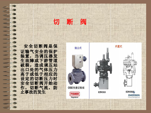
安全切断阀是保 证输气安全的保护 装置,当调压器发 生故障或下游管道 破裂,造成调压站 出口处的气体压力 高于或低于相应的 设定的切断压力时 安全切断阀开始动 作,切断气流,防 止事故的发生
制作人:李少冬
OSE切断阀
制作人:李少冬
限位挡块
制作人:李少冬
制作人:李少冬
制作人:李少冬
制作人:李少冬
制作人:李少冬
Gascat切断阀复位
步骤:
5.缓慢打开切断阀下游阀 6.缓慢全开切断阀上游阀
制作人:李少冬
注 意 事 项
1.当切断阀不容易打开时,严禁强力开启。
2.开启困难时,要考虑切断阀两侧压差较大,或切
断阀切断压力接近于取压点压力。 3.切断阀切断时,复位轴端面呈垂直状态,复位时
,复位轴端面呈平行状态。
切断设定弹簧
制作人:李少冬
注释:金属钩片和D2接触部分为低压切断部分,和D1处为超高切断部分。
制作人:李少冬
制作人:李少冬
Gascat 切 断 阀制作人:李少冬Fra bibliotek复位扳手
复位轴
制作人:李少冬
Gascat切断阀复位
步骤:
1.关闭切断阀出口阀门 2.微开切断阀进口阀门 3.按下切断阀的平衡按钮(内置平衡阀),或打开平衡管阀(外 置平衡阀),平衡切断阀两侧压力。 4.取下阀门上安装的专用扳手,,逆时针转动复位轴,使切断阀 打开。
制作人:李少冬
制作人:李少冬
GASCAT-调压阀手册 ppt

工作监控式:即两台调压器中一台监控,另一台工作,但两台调压器取
压点相同,调压设定点也基本相近。 -
19
并联:两台调压器(调压路)入口与出口分别连接的方式。
工作备用切换式:即两台调压器中一台工作,另一台备用,两台调压器的取压 点相同,调压设定点也基本相近。
5、自用气撬的几点说明
-
15
1、系统工艺流程图
-
16
2、系统配置及原理
根据我国国家标准《输气管道工程设计规范》GB50251以及欧美 国家标准如《燃气输配系统中的调压站—功能要求》EN12186的 要求,燃气调压站、计量站中压力控制系统中的调压阀应优先选 用自力式调压阀,在流通能力方面宜采用流通能力较好的轴流式 调压阀。自力式调压器结构简单、维护方便,以广泛用于国内外 的压力控制系统。
调节原理:当出口用气量增加或入口压力降低时,燃气出口压力下降,造成皮膜上下压 力不平衡,此时皮膜下降,阀口开大,燃气流量增加,使压力恢复平衡状态。反之,当 出口用气量减少或入口压力增大,燃气出口压力升高,此时皮膜上升,使阀门关小,燃 气量减少,又逐渐使出口压力恢复至原来状态。
-
3
1、HORUS 系列轴流式调压阀
3、调压器的关闭特性,即当下游设备不用气或当调压器出口压力高于 设定压力时,调压器的阀口将关闭;
其中,调压器的关闭特性非常重要,它是调压器固有的性 质,关闭特性决定了调压器具有多种连接方式及工作特点。
-
18
2.2 调压器的串联与并联
串联:两台调压器按照从上游到下游的顺序依次连接的方式。
两级调压式:即两台调压器各自调压(取压点不同),比如系统入口压
GASCAT-调压阀手册

5.1、系统配置特点
说明:
站内自用气计量调压系统工艺流程比较复杂, 其关键之处在于每级调压阀设臵了两套切断阀, 设计依据即我国的国家标准《输气管道工程设计 规范》GB50251的标准要求。
5.2、电加热系统说明
接线箱 呼吸孔 电加热芯 最高导热油液位 最低导热油液位
控制箱
天然气壳程
导热油
说明:电加热器是间接换热式结构,加热元件在换热管内,其热量传递给导热油,再传至换热管外 壁(含导流板)。未被加热的天然气自加热器下部进气口进入换热腔,沿导流板旋流至出气口,在 此过程中进行换热升温。在加热器防爆接线盒内安装有升温控制器 WK-R11 和超温保护温度开关 (70℃),其安装套管焊接在换热管外壁上。 防爆控制箱内设有空气开关(具有过载保护,失压脱扣功能),同时箱体上设有电源指示灯, 工作指示灯,超温故障指示灯。防爆电控箱与加热器配套,可实现自动控制。加热器调试后温度控 制器设定在35℃位置(旋动旋纽即可完成),其设定误差为±2℃。切换差为7~9℃。当加热器出口 温度低于设定值时,电加热器自动投入加热(绿灯亮),达到设定值时,温度控制器主触点打开, 加热器停止加热(绿灯灭),出口介质温度降低至设定值以下7~9℃时,加热器重新投入运行。如果 电加热器换热管壁达到75℃时,超稳保护用温度开关常闭接点打开,空气开关的失压脱扣线圈失电 ,空气开关跳闸,其辅助报警开关的触点闭合,超温指示灯红灯亮,说明有超温现象发生。此时加 热器系统不能自动恢复工作,必须查明原因。且温度降低后,才能再重新送电(合上空气开关), 加热器恢复工作。
HORUS的失败关与失败开
其他品牌轴流阀只有失败关型
二、切断阀
又称紧急切断阀:是一个安全装臵,当调压通道内发生故障致使出口压力 升高或降低至预定警戒值时,切断阀自动介入将该通道关闭,避免下游系统压 力异常而危及用户安全。 切断阀也有必须的三个基本部件: (1)敏感元件(皮膜、导压管等):它承受被 控压力的作用,出口压力的升高/降低变化将通 过皮膜使执行机构动作; (2)执行机构:与敏感元件相连,当敏感元件动作时将导致执行机构的挂钩 (杠杆组件)脱扣,由执行机构控制关断阀动作; (3)关断阀:与流动介质直接接触,当执行机构脱扣时,关断阀在弹簧的作用 下向阀口方向运动,最后将阀口关闭。 切断动作原理:敏感元件感受到管道中气体的压力后,将该压力与设定弹簧 压力进行比较,如平衡被破坏,则敏感元件将使执行机构中的杠杆组件脱扣, 从而关断阀在阀体主弹簧的作用下将阀口关闭,达到切断气流的目的。
VPPM-6L-L-1-G18-0L6H-V1N-S1 气动控制阀说明书

比例调压阀zh.................................1功能和应用该VPPM-...用于根据给定的应有值按比例调节压力。
其所配备的集成式压力传感器可感测到工作接口的压力,并将其与应有值进行比较。
当应有值和实际值出现偏差时,调压阀就会一直运行,直到输出压力达到应有值。
+W-W312X压力输入应有值压力输出排气针脚62应用范围及认证UL-提示本系列产品某些型号拥有针对美国和加拿大的UL(Underwriters Laboratories Inc)认证。
这些型号均带有如下标志:注意..................................如果在使用时必须遵守UL要求,则请注意:S可在单独的UL特有专项文献中找到遵守UL认证的规定。
该文献中所记录的技术数据优先适用。
S本说明书中的技术数据有可能与其不同。
3VPPM-...的派生型4产品使用前提条件应随时注意关于正确和安全使用该产品的一般说明:S请您将本操作指南中的极限值与实际使用情况下的极限值进行比较(例如:工作媒介、压力、作用力、力矩、温度、质量、速度、电压)。
S请注意使用地点的环境条件。
S请注意同业公会、技术监督协会、VDE的规定或相关国家法规。
S拆除运输包装材料,例如:防护蜡、薄膜(尼龙)、盖罩(聚乙烯)、纸板箱等。
S这些包装物均为可回收材料(例外情况:油纸=废料)。
S请您在原装状态下使用产品,勿擅自进行任何改动。
S请注意产品上的以及本操作指南中的警告和提示。
S请按规定对压缩空气进行预处理。
(→技术数据)。
S缓慢地给整个设备加压。
这样可以防止出现失控运动。
5安装5.1机械部分安装注意..................................S只能由具有专业资质的人员根据操作指南来进行安装和调试。
S安装VPPM-...时务必注意不能损坏电气连接。
因为这样这会降低功能可靠性。
S注意为电缆连接和气管连接留出足够的空间。
RegO LP-Gas 调压器配件说明书
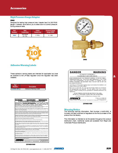
A39A100 RegO Dr. Elon, NC 27244 USA +1 (336) 449-7707 These adhesive warning labels are intended for application as close as possible to the LP-Gas regulator once the regulator has been installed.PartNumberDescription LV4403-400Adhesive Warning LabelAdhesive Warning LabelsDesigned for testing high pressure lines. Adapter has 0 to 300 PSIG gauge. A bleeder valve allows you to bleed down to correct pressure during pressure tests.PartNumberInlet Connection Outlet Connection Pressure Gauge Range (PSIG)2962Soft NoseM. POL F. POL 0 - 300High Pressure Gauge Adapter29622962Warning Notice The following warning information, Part Number LV4403-500, is included with each shipment of regulators to the first purchaser of the product from the factory.This information is intended to be forwarded throughout the product distribution chain. Additional copies are available from RegO and Authorized Product Distributors.AVOID SERIOUS INJURY AND PROPERTY DAMAGE. IF YOU SEE, SMELL OR HEAR ESCAPING GAS...EVACUATE AREA IMMEDIATELY! CALL YOUR LOCAL FIRE DEPARTMENT! DO NOT ATTEMPT TO REPAIR. DO NOT STORE IN BUILDING OR ENCLOSED AREA. DO NOT USE ON HOT AIR BALLOONS OR AIRCRAFT.DANGER WARNINGMake sure you are thoroughly trained before you attempt any regulator installation or maintenance. Improper conditions or procedures can cause accidents resulting in property damage and personal injury.Become thoroughly familiar with NPGA Safety Pamphlet 306 “LP-Gas Regulator and Valve Inspections & Maintenance” and RegO Safety Warning “LP-Gas Regulators” found in the regulator section of the L-500 & L-102 Catalogs. Follow its recommendations. Know and understand NFPA Pamphlet 58 “Liquefied Petroleum Gas Code”, which is the law in many states. This publication is available from NFPA, Batterymarch Park, Quincy, MA 02269. Following its requirements is essential in the safe use of LP-Gas. Section 4.4 states: “Persons who transfer liquid LP-Gas, who are employed to transport LP-Gas, or whose primary duties fall within the scope of this code shall be trained in proper handling procedures. Refresher training shall be provided at least every three years and shall be documented.”Pamphlet 58 also states that “All regulators for outdoor installations, except regulators used for portable industrial applications, shall be designed, installed or protected so their operation will not be affected by the elements (freezing rain, sleet, snow, ice, mud or debris). This protection may be integral with the regulator.”Vents must be clear and fully open at all times. An obstructed vent will prevent the regulator from functioning properly and may result in property damage and personal injury.Regulators should be installed with the vent facing down or otherwise covered for protection.Twin-Stage Regulators should be installed completely under cover and/or with screened vent pipe away adapters that position both vents in a down position without obstructing flow through the vents.Make sure piping is clean and free from foreign material (such as dirt, corrosion, chips, pipe joint compound, etc.) Always replace the pigtail when replacing a regulator. Thread sealant used on piping must be compatible with LP-Gas.Make sure the use and location of the regulator(s) as a component(s) of the LP-Gas system to be installed is proper. (Avoid misusing LP-Gas equipment.) See the following RegO publications: L-500 & L-102 Catalogs and the LP-Gas Serviceman’s manual.For underground installations, make sure that water, mud, dirt, and insects cannot get into the regulator, and that the regulator is easily accessible for regulator maintenance. Follow NPGA Bulletin 401. See RegO Safety Warning “LP-Gas Regulators” found in the regulator section of the L-500 & L-102 Catalogs.Check regulator and installation for leaks following NFPA #54 and NPGA Bulletin 403 “Pressure T esting and Leak Checking LP-Gas Piping Systems”.In selecting a label for posting at the installation site, consider RegO part number 2403-400 along with your own, NPGA’s and others.Remember to instruct the owner/user/customer in safety matters concerning LP-Gas and this equipment. See RegO Safety Warning “LP-Gas Regulators” found in the regulator section of the L-500 & L-102 Catalogs.LP-GAS IS EXTREMELY FLAMMABLE AND EXPLOSIVE READ THIS FIRSTPrinted in USA 08A-0910-0390Part number LV4403-500RegO requests that this information be forwarded to your customers. Additional copies are available from RegO and your authorized RegO Distributor.Elon, N.C. 27244 U.S.A. Phone (336) 449-7707 Fax (336) 449-6594 10R E G O P R O D U C T S10 Y E A R W A R R A N T Y LV4403-400LV4403-500。
燃烧机调压阀的使用方法

燃烧机调压阀的使用方法
燃烧机调压阀是用来控制燃气或液化石油气的压力,以确保燃烧机正常运行的重要部件。
其使用方法如下:
1. 安装,首先,确保燃烧机调压阀的安装位置符合要求,安装前应仔细阅读产品说明书。
安装时要确保阀门方向正确,并且紧固螺栓牢固可靠。
2. 调节压力,在使用前,需要根据燃气或液化石油气的压力要求,通过调节燃烧机调压阀上的调节旋钮或手柄来设定合适的压力数值。
调节时应该小心谨慎,避免调节过大或过小。
3. 检查安全,在使用过程中,定期检查燃烧机调压阀的工作状态,确保没有泄漏或损坏现象。
同时,还需要检查阀门和连接管路是否牢固,确保安全使用。
4. 维护保养,定期对燃烧机调压阀进行清洁和润滑,确保阀门的灵活性和密封性。
同时,注意防止灰尘和杂物进入阀门内部,以免影响正常使用。
5. 注意事项,在使用燃烧机调压阀时,要注意避免阀门受到外力撞击,防止损坏;同时,要避免阀门长时间处于高温或潮湿环境中,以免影响阀门的使用寿命和性能。
总之,燃烧机调压阀的使用方法包括安装、调节压力、检查安全、维护保养和注意事项等多个方面,只有正确使用和维护,才能确保燃烧机的正常运行和安全使用。
天然气调压区调压阀操作规程
天然气调压区调压阀操作规程一、新费舍阀(13,FISHER自励式调节阀)流程的操作规程1、检查新费舍阀(13)前后所有管线正常,无泄漏情况。
2、检查进气总管压力表指示正常,压力应在2.0-2.3MPa之间。
3、手动打开新费舍阀前的隔离阀(12),检查费舍阀阀前压力表指示正常,压力应在2.0-2.3MPa之间。
4、手动缓慢打开费舍阀后的隔离阀(14),检查费舍阀阀后压力表指示,压力应在1.6MPa左右。
5、新费舍阀(13)后压力值高于1.8MPa或低于1.55MPa时,可对新费舍阀进行调节,使新费舍阀阀后压力维持在1.6MPa左右。
调节方法如下:5.1、松开新费舍阀(13)调节器上的固定螺母。
5.2、调节调节器上的螺杆,顺时针调整时,新费舍阀阀后压力增大。
逆时针调整时,新费舍阀阀后压力减小。
5.3、调节调节器上的螺杆,使新费舍阀阀后压力维持在1.6MPa左右后,固定好调节器上的固定螺母。
6、检查天然气管线无泄漏情况,各压力表指示正常。
二、新费舍阀异常情况下流程切换的操作规程当新费舍阀(13)后压力值高于1.8 MPa或低于1.55MPa,对新费舍阀进行调节后,压力仍然无法恢复正常时,必须对新费舍阀流程进行切换操作。
1、手动打开旧费舍阀(16,FISHER副自励式调节阀)前的隔离阀15,检查旧费舍阀(16)阀前压力表指示正常,压力应在2.0-2.3MPa之间。
2、手动缓慢打开旧费舍阀(16)后的隔离阀17,检查加热器后集气母管压力表指示,压力应在1.65MPa左右。
3、手动关闭新费舍阀(13)阀前、后的隔离阀12、14。
4、当旧费舍阀(16)也出现故障时,手动打开费舍阀的两个旁路阀51、52;5、关闭旧费舍阀(16)前、后隔离阀15、17。
6、联系输气总站降低来气压力,使旧费舍阀后的压力低于1.8MPa。
三、天然气调压区夏季巡视检查内容1、检查天然气压力、温度、流量表计指示正常。
2、检查天然气各阀门的位置正常、无泄漏情况。
调压器使用手册

指挥器 型号
弹簧代码
860125
860225
PRS80/ BP
860325 860425 860525
860625
860725
860425
PRS80/ MP
860525 860625 8611 AP
861325 861425 861525
PRS80/ HP
861725
丝径 2.5 3 3.5 4 4.5 5 6 4 4.5 5 5.5 6 7 8 9
表 4 故障分析表
故障现象
下游没有气, 调压器不过气
调压器出口 设定压力降低
调压器关闭不严
调压器喘气
故障原因
上游无压力
指挥器故障
调压器主皮膜破损 进口压力不够 实际流量超过调压器的设计流 量 指挥器进气部分部分堵塞 指挥器控制弹簧疲劳 阀口垫磨损 阀筒密封环磨损 指挥器阀口关不严 下游取压信号管位置不对 流量太小
用户参考:
调压器上游及下游应安装截断流体用的阀门;
调压器上游及下游应安装压力表或压力变送器;
调压器上游应安装过滤器;
调压器下游应安装排气阀以供调试及压力设定时使用;
调压器下游应安装安全放散阀以防止下游压力的异常升高(如当零流量时,下游露
天管道受太阳的长时间照射而导致下游压力的上升);
需要充裕的调压器安装、维修、维护和操作空间和通道;
SPL3000 /SIL II 460 1990 4245 7518 -
五、调压器工作原理
调压器的皮膜总成部分(与调压器的阀筒联接在一起)将调压器的执行机构分成两个 腔室。一个腔室与要控制的下游压力相通的,另一个腔室与指挥器所产生的驱动压力相 通。没有气通过时,在调压器主弹簧的作用下,调压器的阀口是关闭的。
斯普兰蒸汽压力调节阀说明书

Sporlan Crankcase Pressure Regulating Valves are designed to prevent overloading of the compressor motor by limiting the crankcase pressure during and after a defrost cycle or after a normal shutdown period. When properly installed in the suc-tion line, these valves automatically throttle the vapor flow from the evaporator until the compressor can handle the load. Sporlan manufactures three adjustable models: the CRO-4, CRO(T)-6 and CRO(T)-10. All models are available in various adjustment ranges.FOR USE ON REFRIGERATION and/or AIR CONDITIONING SYSTEMS ONL YBulletin 90-10, July 2003, supersedes Bulletin 90-10, dated October 1994, and all prior publicationsCOPYRIGHT 2003 BY SPORLAN VALVE COMPANY , WASHINGTON, MO 63090July 2003 / Bulletin 90-10CRO-10Listed and Certified400 psig Maximum Rated PressureCRO-4Recognized500 psig Maximum Rated PressureCROT-6Listed and Certified400 psig Maximum Rated Pressurefor Compressor Overload ProtectionVALVE GRADIENT –For any pressure sensitive valve tomodulate to a more closed or open position, a change in the operating pressure is required. The unit change in the valve stroke for a given change in the operating pressure is called the valve gradient. Every valve has a specific gradient designed for the best possible oper-ation. Valve sensitivity or how the CRO valve reacts to a change in suction (crankcase) pressure and the valve's capacity rating are functions of the valve gra-dient. For a given set of operating conditions, a greater difference between the suction pressure and the valve setting strokes the valve more in the open direction to obtain greater valve capacity. Once the valve is fully opened, only an increase in pressure drop across the port will increase valve capacity. Because of these interacting factors, all must be considered when a crankcase pressure regulating valve is being selected.CR VALVE PERATI N –Crankcase pressureregulating valves (sometimes called suction pressure regulating valves) are sensitive only to their outlet pressure (compressor crankcase or suction pressure).To indicate this trait, the designation for our crankcase pressure regulating valves describes the operation: Close on Rise of Outlet pressure or CRO. Figure 1 illustrates either a CRO(T)-6 or CRO(T)-10.In these valve models, the inlet pressure is exerted on the underside of the bellows and on top of the seat disc. Since the effective area of the bellows is equal to the area of the port, the inlet pressure cancels out and does not affect valve operation. The valve outlet pres-sure acting on the bottom of the disc exerts a force in the closing direction. This force is opposed by the adjustable spring force and these are the operating forces of the CRO. The CRO's pressure setting is deter-mined by the spring force. The CRO-4 is shown in Figure 2. This model has balanced piston design which cancels out both inlet and outlet pressure from acting on the piston. The outlet pressure is sensed under the diaphragm around the pushrod. This pressure,combined with the spring force under the piston,is exerted in the closing direction. The opening force is provided by the adjustable spring element assembly.The CRO’s pressure setting is determined by thespring force exerted on top of the diaphragm. Thus, by increasing the adjusting spring force, the valve setting or the pressure at which the valve will close is increased.As long as the valve outlet pressure is greater than the valve pressure setting, the valve will remain closed. As the outlet pressure is reduced, the valve will open and pass refrigerant vapor into the compressor. Further reduction of the outlet pressure will allow the valve to open to its rated position where the rated pressure drop will exist across the valve port. An increase in the outlet pressure will cause the valve to throttle until the pressure setting is reached.The CRO(T)-6 and CRO(T)-10 valves are built with an anti-chatter device which is designed to minimize the damaging effect of compressor pulsations on the valve’s bellows. This feature allows the CRO to func-tion at low load conditions without any chattering or other operational difficulties. The CRO-4 does not require this device because the pulsations are damp-ened before reaching the underside of the diaphragm.The function of the crankcase pressure regulating valve is similar to the practice of manually throttling the compressor suction service valve until the machine can handle the load. While either device will increase the pulldown period, they are essential in order to pro-tect the compressor. To properly apply a crankcase pressure regulating valve, several system and valve factors must be considered.TYPE O F SYSTEM –A crankcase pressure regulatingvalve is applicable on any system on which the com-pressor motor can be overloaded due to high suction pressures. This condition is determined by the specific system design pressures and the compressor manufac-turer's application limitations. Care should be taken to completely evaluate a possible compressor overload condition on any refrigeration system being designed.CRO LOCATION –As figure 3 illustrates, the CRO valveis applied in the suction line between the evaporator and the compressor. Normally, the CRO is installedSeatOutletSeat Disk InletAccess Valve (Optional)BellowsAdjusting Spring Spring ForceFigure 1Page 2 / BULLETIN 90-10CROT-10BULLETIN 90-10 / Page 3Page 4 / BULLETIN 90-10The CRO-4 is a Recognized Component by Underwriter’s Laboratories Inc. for the U.S. and Canada - Guide SFQ8, File No. SA-5460. Maximum rated pressure of 500 psig (3448) kPa).The CRO(T)-6 and CRO(T)-10 are Listed by Underwriters Laboratories, Inc. – Guide SF JQ, File No. SA5460. Canadian Standards Association, File LR36628. Maxium rated pressure of 400 psig.SN O I T s e h c n I -s n o i s n e e W CDt e k c o S ht p e D N ——23.0.1——73.——————73.656.305.0.173.657.357.0.173.657.319.2.118.249.0—0.100.360.1—0.105.652.357.5.205.652.319.5.205.652.379.5.2Note: Because both the CR O(T)-6 and CR fitting sizes, and because pressure drop is critical, CR should not be selected on the basis of line size.CRO(T)-6CRO(T)-10BULLETIN 90-10 / Page 5REFRIGERANT 22 - CAPACITIES – TonsCapacities based on 100°F condensing temperature, 10°F superheat, and 0°F subcoolingPage 6 / BULLETIN 90-10Numbers shown in italic indicate vacuum in inches.BULLETIN 90-10 / Page 725-703Page 8 / BULLETIN 90-10ORDERING INSTRUCTIONSTo eliminate delays in shipments, specify complete valve designation:OR C -T-01-06/0-FD O 8/1-1e p y T e v l a V C no e s o l R f o e s i O te l t u er u s s e r P n o e v l a V s s e c c A no i t c e n n o C t e l n I r o 6-T O R C 01-T O R C sh t h g i E n i e z i S t r o P hc n I n a f o gi s p -e g n a R t n e m t s u j d A el b a l i a v a r o f s n o i t a c i f i c e p S e e S se g n a r t n e m t s u j d a re d l o S F D O -s n o i t c e n n o C er a l F E A S r o。
阿拉夫拉夫常压调节阀(CPM-I-D60)说明说明书
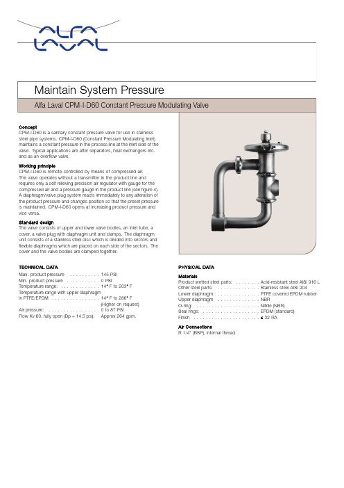
TECHNICAL DATAMax.product pressure..........145PSIMin.product pressure...........0PSI Temperature range:.............14°F to203°F Temperature range with upper diaphragmin PTFE/EPDM................14°F to286°F(Higher on request) Air pressure:.................0to87PSIFlow Kv60,fully open(Dp=14.5psi):Approx264gpm.PHYSICAL DATAMaterialsProduct wetted steel parts:........Acid-resistant steel AISI316L Other steel parts:..............Stainless steel AISI304 Lower diaphragm:..............PTFE covered EPDM rubber Upper diaphragm..............NBRO-ring:.....................Nitrile(NBR)Seal rings:...................EPDM(standard) Finish......................≤32RAAir ConnectionsR1/4"(BSP),internal thread.Pressure Drop/Capacity Diagram PSIStroke (%)T D 433-031Note!For the diagram the following applies:Medium:Water (68°F)Measurement:In accordance with VDI 2173Example of using the diagram:1.Pressure drop ∆p =36PSI 2.Flow =220GPMThe intersection is on the 50%curveNote!Always try to get as near as possible to the 50%open curve.If the CPM-I-D60is too big,select from the CPMI-2curves.Options Equipment •Male parts or clamp liners in accordance with required standard •Pressure gauge 0-87PSI,1.5-inch •Pressure gauge 0-145PSI,1.5-inch •Pressure gauge 0-145PSI,2-inch•Air pressure regulating valve kit,0-116PSI•Booster for product pressure exceeding the available air pressure.(Product pressure =1.8x air pressure)•Material Grades•Upper diaphragm of PTFE covered EPDM rubber (for temperatures 194°F -284°F)•Valve body seal rings of Nitrile (NBR)or Fluorinated rubber (FPM)•Guide O-ring of Fluorinated rubber (FPM),(for temperatures above 203°F)Dimensions (inches)Size 3-inch A116.27A216.93C 6.10OD 3.00ID 2.83t 0.079F 0.66G1 2.09G29.45H0.83Weight (lbs.)22.00OrderingPlease state the following when ordering:•Valve type CPM-I-D60•Diaphragm type if not standard •Connections if not welding ends •Pressure gauge size if required•Air pressure regulating valve kit,if required •Other optionsESE02932ENUS1505Alfa Laval reserves the right to change specifications without priornotification.ALFA LAVAL is a trademark registered and owned by Alfa LavalCorporate AB.©Alfa LavalHow to contact Alfa LavalContact details for all countriesare continually updated on our website. Please visit toaccess the information direct.。
A-T Controls FR100-1 滤芯 调压器操作手册说明书
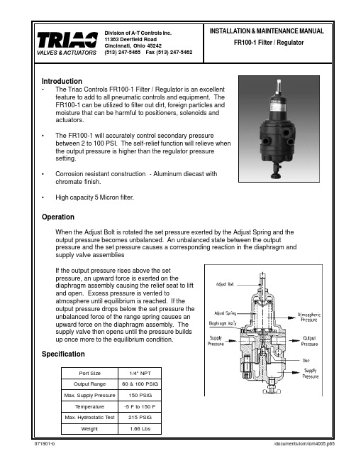
INSTALLATION & MAINTENANCE MANUAL FR100-1 Filter / Regulator
C3604 BD
1
7
Low Diaphragm Plate
SS41
1
8
Relief Seat
C3604 BD
1
9
Diaphragm
NBR
1
10
Adjust Spring
HSW 3
1
11
Up Diaphragm Plate
SS41
1
12
Filter
PA
1
13
Adjust Bolt
SS41Biblioteka 114 Top Spring Seat
SS41
1
15
Gasket
EPDM
1
16
Name Plate
Sticker
1
17 Disc Con Spring
STS304
1
18 Holder Con Spring
STS304
1
19
Lock Nut
SS41
1
20
Drain Plug
C3604 BD
1
21 Spring Case Bolt
SS41
6
• To remove accumulated condensation from the Filter / Regulator, slowly open the Drain Plug and bleed liquid out. Sediment should not be permitted to fill above the filter element.
- 1、下载文档前请自行甄别文档内容的完整性,平台不提供额外的编辑、内容补充、找答案等附加服务。
- 2、"仅部分预览"的文档,不可在线预览部分如存在完整性等问题,可反馈申请退款(可完整预览的文档不适用该条件!)。
- 3、如文档侵犯您的权益,请联系客服反馈,我们会尽快为您处理(人工客服工作时间:9:00-18:30)。
1)在工作调压器上游设置; 2)在工作调压器下游设置。 3)两级调压+工作监控
17
2.1 调压器的特性
气体经过调压器前后的变化: 1、压力降低;
2、密度减小;
3、温度降低;温度降低的根本原因在于阀门的节流效应,即当气体经过 阀口(小孔)时,发生绝热膨胀,气体的内能(热能)转化为动能,故 温度降低。 调压器具有以下特性: 1、压力调节特性; 2、流量变化范围大,可在2%—100%之间正常工作;
3、调压器的关闭特性,即当下游设备不用气或当调压器出口压力高于 设定压力时,调压器的阀口将关闭;
其中,调压器的关闭特性非常重要,它是调压器固有的性 质,关闭特性决定了调压器具有多种连接方式及工作特点。
18
2.2 调压器的串联与并联
串联:两台调压器按照从上游到下游的顺序依次连接的方式。
两级调压式:即两台调压器各自调压(取压点不同),比如系统入口压
力30bar,一级调压至16bar,经过二级调压器后将压力调为5bar。
工作监控式:即两台调压器中一台监控,另一台工作,但两台调压器取
(调压路)入口与出口分别连接的方式。
工作备用切换式:即两台调压器中一台工作,另一台备用,两台调压器的取压 点相同,调压设定点也基本相近。
GASCAT生产的的HOURS系列轴 流阀具有以下性能特点:
✓ 全通径流量特性 ✓调节精度可达 +/- 1% ✓ 关闭压力精度 2.5% ✓ 打开的最小压差 0.5bar ✓内置平衡阀 ✓ 轴流特性 ,流通能力大 ✓ 低压损 ✓调节范围大
4
1.1 工作原理图解
5
1.2、GASCAT、TARTARINI、RMG轴流阀的相似性
15
1、系统工艺流程图
16
2、系统配置及原理
根据我国国家标准《输气管道工程设计规范》GB50251以及欧美 国家标准如《燃气输配系统中的调压站—功能要求》EN12186的 要求,燃气调压站、计量站中压力控制系统中的调压阀应优先选 用自力式调压阀,在流通能力方面宜采用流通能力较好的轴流式 调压阀。自力式调压器结构简单、维护方便,以广泛用于国内外 的压力控制系统。
燃气调压系统专题
技术交流
博思特石油天然气设备有限公司 二零零七年三月
1
技术交流准备内容 一、调压阀(HORUS轴流式) 二、切断阀(翻板式GIPS系列) 三、压力控制系统和自用气 四、GASCAT调压阀的业绩
2
一、调压阀(HORUS轴流式)
调压阀:是将较高的入口压力调至较低的 出口压力,并随着用气量的变化自动地保持 其出口压力为定值,完成降压稳压功能。
6
1.2、 GASCAT、TARTARINI、RMG轴流阀的相似性
7
1.3 GASCAT的独特优势
GASCAT生产的的HOURS系列轴流阀真正实现了主 阀的“失败开”和“失败关”,这是世界上独一无二的 技术特点,有别于其他类型的轴流阀。
GASCAT生产的的HOURS系列轴流阀其流量系数优 于其它品牌的轴流阀产品。
20
2.3 系统配置及原理
系统为轴流式的配置方案
Shut off valve
Monitor
Regulator
21
指挥器的失败开与失败关
22
3、限流限压LC21系统说明
23
LC21与调压器上的指 挥器的连接方法
调压器所必须的三个基本部件:
(1)敏感元件(皮膜、导压管等):它承受被控压力的 作用,出口压力的任何变化通过皮膜使节流阀移动;
1、皮膜;2、负载;3、节流阀
(2)负载(给定压力部件):给定压力值可以由固定的重块、弹簧或直接作用于皮膜上 的燃气压力确定,它与被控压力作用方向相反;
(3)可调节流阀:它设置在燃气流中,受敏感元件(皮膜)的控制。该节流阀可以是提 升阀、滑动阀、活塞阀、蝶阀、旋塞阀等。
调节原理:当出口用气量增加或入口压力降低时,燃气出口压力下降,造成皮膜上下压 力不平衡,此时皮膜下降,阀口开大,燃气流量增加,使压力恢复平衡状态。反之,当 出口用气量减少或入口压力增大,燃气出口压力升高,此时皮膜上升,使阀门关小,燃 气量减少,又逐渐使出口压力恢复至原来状态。
3
1、HORUS 系列轴流式调压阀
11
GIPS系列 切断阀
✓ 翻板式 ✓ 低压损 ✓ 全通径 ✓ 阀座保护 ✓ 反应时间小于1秒 ✓ 控制精度 +/- 1%
12
切断阀的执行机构
13
GIPS与RMG711切断阀
14
三、压力控制系统与自用气
1、系统工艺流程图 2、系统配置及原理 3、限流限压LC21系统说明 4、附件说明 5、自用气撬的几点说明
以上几种工作方式中,监控工作式和工作备用切换式用的非常普遍。这两 种工作方式的精髓在于调压器的关闭特性。
对于监控工作式,监控调压器的设定压力高于工作调压器的设定压力。即 遵循“谁低谁工作”的原则。也就是哪个调压器设定的出口压力低,则该调压 器为工作调压器。与两台调压器哪个在前哪个在后没有关系。
对于工作备用切换式,备用调压器的设定压力低于工作调压器的设定压力。 即遵循“谁高谁工作”的原则。也就是哪个调压器的出口压力高,则该调压器 为工作调压器。与监控工作式的原则相反。
(2)执行机构:与敏感元件相连,当敏感元件动作时将导致执行机构的挂钩 (杠杆组件)脱扣,由执行机构控制关断阀动作;
(3)关断阀:与流动介质直接接触,当执行机构脱扣时,关断阀在弹簧的作用 下向阀口方向运动,最后将阀口关闭。 切断动作原理:敏感元件感受到管道中气体的压力后,将该压力与设定弹簧压 力进行比较,如平衡被破坏,则敏感元件将使执行机构中的杠杆组件脱扣,从 而关断阀在阀体主弹簧的作用下将阀口关闭,达到切断气流的目的。
8
HORUS的失败关与失败开
9
其他品牌轴流阀只有失败关型
10
二、切断阀
又称紧急切断阀:是一个安全装置,当调压通道内发生故障致使出口压力 升高或降低至预定警戒值时,切断阀自动介入将该通道关闭,避免下游系统压 力异常而危及用户安全。
切断阀也有必须的三个基本部件:
(1)敏感元件(皮膜、导压管等):它承受被 控压力的作用,出口压力的升高/降低变化将通 过皮膜使执行机构动作;