丰田普锐斯培训资料can (for prius) rev
丰田普锐斯培训资料-- PRIUS THSII
Refer to chart
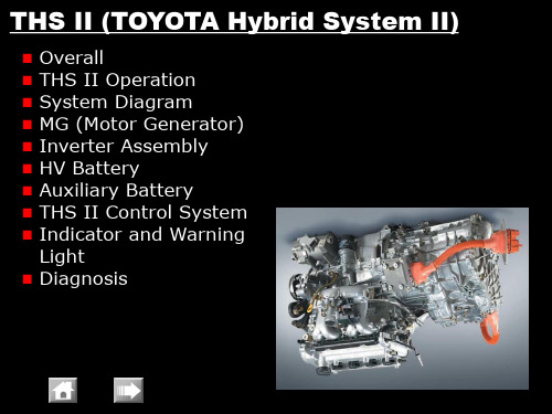
THS II
-A -K -W -Q
THS II Operation • Vehicle Start off with engine starting – MG1 operates to start the engine
Driven
Refer to chart
THS II
MG2 Rotor (’04 PRIUS)
MG2 Rotor (’03 PRIUS)
THS II
-A -K -W -Q
MG (Motor Generator) • Specifications
– MG1
Item
’04 PRIUS
Type
Synchronous AC Motor
Function
Generator, Engine Starter
THS II
THS II Operation • Nomographic chart
– Vertical lines show rpm and direction of rotation for: ➢ Sun Gear ➢ Planetary Carrier ➢ Ring Gear
– Spaces between vertical lines show gear ratios
Refer to chart
THS II
-A -K -W -Q
THS II Operation • During Slight Acceleration with Engine
Click! Movie
Click! Movie
THS II
-A -K -W -Q
THS II Operation • During Full Throttle Acceleration – Electricity to MG2 is supplied by MG1 and HV battery
PRIUS新机构培训
混合动力汽车( Hybrid vehicles)
Toyota & Lexus 销售数据
• 2004 HV 销售量: • 世界总销售量: 180 000 •占全部销售量% : 2,7%
•2005 HV 销售量: •世界总销售量: 300 000 •占全部销售量% : 4,1%
•2009 HV销售量: •世界总销售量:1 000 000 •占全部销售量% :10%
– 直流-直流 转换
直流 200V 降至 直流 12V
– A/C 变频器
DC AC 驱动 A/C 压缩机
Prius介绍
THS II 系统操作 (概要) (发动机起动和怠速空转)
发动机起动时MG1 作为起动机运转
发动机怠速空转时MG1 发电, 暖机后发动机停机
Prius介绍
电子换档系统 电子换档系统采用瞬间型换档杆
020 12:51:10 AM00:51:102020/9/15
• 11、自己要先看得起自己,别人才会看得起你。9/15/2
谢 谢 大 家 020 12:51 AM9/15/2020 12:51 AM20.9.1520.9.15
• 12、这一秒不放弃,下一秒就会有希望。15-Sep-2015 S eptember 202020.9.15
10
更好的加速性
基本操作
混和动力汽车更具燃油经济性的原因
动力不足时补充
HV 电池
+
行驶动力
发动机输 出动力 能量
提供能 量储存
制动能量 回收
-
停止 开始行驶
全加速
正常行驶
制动
基本操作
THS-II 驱动力特征
驱动力
全加速
丰田普锐斯混合动力汽车构造与维修PPT课件

HV蓄电池
第三章 丰田普锐斯混合动力汽车构造与维修
3. 变频器总成
变频器总成
第三章 丰田普锐斯混合动力汽车构造与维修
(1)作用及组成 变频器总成用于将高压直流电(HV 蓄电池)转换为 交流电(发电机MG1和电动机MG2);反之亦可,将交流 电(AC) 转换为直流电(DC)。其组成部件包括增压 转换器、DC/DC转换器和空调变频器。
第三章 丰田普锐斯混合动力汽车构造与维修
④发电机(MGl)和电动机(MG2)冷却系统
变频器、发电机(MGl)和电动机(MG2)的冷却系统
第三章 丰田普锐斯混合动力汽车构造与维修
4. HV ECU 5. 发动机ECU 6. 蓄电池ECU 7. 制动防滑控制ECU
第三章 丰田普锐斯混合动力汽车构造与维修
第三章 丰田普锐斯混合动力汽车构造与维修
14. 电线
高压电线 1-接线盒 2-变频器 3-空调压缩机 4-穿过中央地板的部分5-备用
蓄电池 6-HV蓄电池 7-电线电压(+) 8-电线电压(-) 9-DC 12V(+)
第三章 丰田普锐斯混合动力汽车构造与维修
三、丰田混合动力系统工作原理
1. 工作状态 (1)HV蓄电池向电动机(MG2)供电,以驱动车辆
第三章 丰田普锐斯混合动力汽车构造与维修
§3-1 丰田混合动力系统 §3-2 普锐斯混合动力系统主要部件 §3-3 普锐斯混合动力系统的维修
第三章 丰田普锐斯混合动力汽车构造与维修
§3-1 丰田混合动力系统
任务目标
1. 了解普锐斯混合动力系统的技术特点 2. 掌握混合动力系统的组成 3. 掌握丰田混合动力系统工作原理 4. 熟悉丰田混合动力控制系统
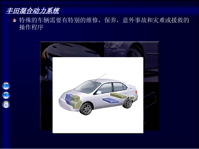
丰田普锐斯维修培训教材—-—原厂2010

7
车型概述
性能
注意事项
混合动力
发动机
动力总成
[P410 混合驱动桥] - 电子控制连续可变型变速器包括MG1, MG2 和组合齿轮
底盘
车身电气
-A -K -W -Q
- 电子换挡系统
MG1 - 最大系统电压: AC 650 V
MG2 - 最大系统电压: AC 650 V - 最大输出功率: 60 kW (80 HP)
15
电缆 电源控制 ECU (HV CPU)
ECM
P410 Hybrid 驱动桥
• MG1
• MG2
车型概述
设备
注意事项
混合动力
发动机
电子换档系统 –换档杆
• 该系统应用线控换挡技术实现档域变换
底盘
车身电气
-A -K -W -Q
P 档开关
操作信号
[换档位置指示器]
仅通过电子 方式接通
换档杆 驻车锁止执行器
HV 电池单元 • 电池模组
(DC 201.6 V) • 接线盒 • 电池智能单元
动力总线 电源控制 ECU (HV CPU)
变频器总成
• 升压转换器
• 变频器
• MG ECU
• 辅助电池直流转换器
ECM
P410 混合驱动桥
• MG1
• MG2
6 注意: 最大系统输出表示发动机输出和HV电池输出总和
发动机
底盘
车身电气
-A -K -W -Q
4
车型概述
内饰
注意事项
混合动力
发动机
底盘
车身电气
-A -K -W -Q
5
车型概述
性能
注意事项
丰田PRIUS普锐斯混合动力汽车CAN系统概要

Lo
Lo
Twisted-pair Wire
AV Single Wire
CAN Communication
Feature • Communication signal
[CAN HI]
3.5 V
2.5 V
0V
Time
[Output Voltage]
[CAN LO]
2.5 V 1.5 V Time CAN HI
Header Data Length
Data
Priority
Error Detection Code Communication Frame
CAN Communication
Feature • Communication Type – Bus Style
Yaw Rate Sensor Deceleration Sensor
Location
Gateway ECU HV ECU Engine ECU J/C No. 2
EPS ECU J/C No. 1
Yaw Rate and Deceleration Sensor
Skid Control ECU源自Steering Angle Sensor DLC3 Battery ECU
1. Bus Check 2. CAN Bus Line Check
Function
Bus Check System
View
System
Bar
Help
Current OK OK 1 OK OK OK
Engine and ECT Air Suspension ABS/VSC Laser Cruise Air Conditioner Immobiliser SRS Airbag Gateway Body No.2 Body No.4 Body No.5 < Back DTC Data List Details Next > View Active Test
00丰田普锐斯培训--中文史上最完整版【强烈推荐】(431页)
使用发动机室的 ”+” 极跨接端子
丰田混合动力驱动系统
路边援助
+
跨接电线
外部跨接起动端子
跨接电线 12 V 蓄电池跨接起动
正极端子
+
负极端子 _
12 V 蓄电池
• 按a, b, c, d优先顺序选择 连接跨接电线
12 V 蓄电池
_
维修服务
Toyota Motor Marketing Europe
将换档杆切换到P档位
17
程序
使用驻车制动器
18
程序
拔下点火钥匙
19
程序
断开辅助电池的负极端子
20
程序
戴上绝缘手套,拆下维修塞
维修插销
21
程序
如果因为损坏或其它的原因无法取下HV电池维修塞 在发动机室内接线盒中取下HV保险丝
22
移动 & 拖拽 Prius
如果出现如下情况,车辆必须被拖拽… 任何高压系统组件或线路损坏 制动,转向,动力分配或燃油系统被损坏 钥匙插入后, READY 灯不点亮
DC
电机 变频器
接地故
障监视器
车辆计算机 (
继电器关闭) 12-V蓄电池
•高压安全系统 –接地故障监视器:
•主警告灯亮 •混合动力警告灯亮
--停止电流流动
•通过SRS气囊传感器总成 •通过转换器内部的电路切断传感器.
丰田混合动力驱动系统
紧急对应
救援
• 固定车辆
– 不要放顶块在高压电缆,排气管或燃油箱下面
• 吸收: • 冲洗被污染的部件区域 20 分钟
• 无失火时吸入:
•正常情况下不会产生有毒气体 •失火时吸入:
丰田THS混合动力系统组成及其维修培训

任务分析
要熟悉普锐斯混合动力汽车的技术特点,掌握丰田混合动力 系统的组成、工作原理和混合动力控制系统,需以下几个步骤:
1
归纳总结普锐斯混合动力系统的技术特点
2
分析丰田混合动力系统的组成和工作原理
3
分析丰田混合动力控制系统
6
一、普锐斯混合动力汽车技术特点
THS-Ⅱ组成简图 1-减速器 2-行星齿轮机构 3-发动机 4-MG1(发电机) 5-HV(混合动力汽车)蓄电池 6-变频器 7-MG2(电动机)
15
丰田混合动力系统主要部件的位置(2)
16
1. HV(混合动力汽车)变速驱动桥
MG1和MG2 1-MG1 2-MG2
17
发电机(MGl)和电动机(MG2)电路图
18
发电机(MGl)和电动机(MG2)的工作原理
19
2. HV蓄电池
HV蓄电池
20
3. 变频器总成
变频器总成
21
(1)作用及组成 变频器总成用于将高压直流电(HV 蓄电池)转换为 交流电(发电机MG1和电动机MG2);反之亦可,将交 流电(AC) 转换为直流电(DC)。其组成部件包括增 压转换器、DC/DC转换器和空调变频器。
发动机驱动车轮
34
(3)发电机(MGl)由发动机通过行星齿轮机构带动旋 转,为HV蓄电池充电
发动机发电
35
(4)车辆减速时,车轮的动能被回收并转化为电能, 并通过电动机/发电机为HV蓄电池再次充电
车轮的动能回收
36
2. 工作原理
车辆行驶状况
37
行星齿轮组与发动机、MG1和MG2连接关系 1-驱动链 2-发动机 3-MG1 4-太阳轮 5-环齿圈 6-MG2 7-行星架
丰田普锐斯电机及驱动控制系统解析(收藏)

丰田普锐斯电机及驱动控制系统解析作为全球最成功的环保车型,丰田普锐斯(PRIUS)早已成为油电混合动力车型中的全球销量冠军,即使在我们的身边,也经常可以见到它们的身影。
目前,在国内生产的丰田普锐斯(PRIUS)是采用丰田第二代混合动力系统,集发动机和电动机组合而成的并行混合动力车(图1)。
丰田第二代混合动力系统(THS-Ⅱ),可以根据车辆行驶状态,灵活地使用2种动力源,并且弥补2种动力源之间不足之处,从而降低燃油消耗,减少有害气体排放,发挥车辆的最大动力。
由于其THS-Ⅱ电机及驱动系统结构复杂,技术先进,本文将为大家详细介绍该系统的结构及基本原理,以帮助读者更进一步了解THS-Ⅱ系统。
一、THS-Ⅱ电机及驱动控制系统的特点1.在电动机和发电机之间采用AC500V高压电路传输,可以极大地降低动力传输中电能损耗,高效地传输动力。
2.采用大功率电机输出,提高电机的利用率。
当发动机工作效率低时,此系统可以将发动机停机,车辆依靠电机动力行驶。
3.极大地增加了减速和制动过程中的能量回收,提高能量的利用率。
二、THS-Ⅱ电机及驱动系统基本组成1.HV蓄电池:由168个单格镍氢电瓶(1.2V×6个电瓶×28个模块)组成,额定电压DC20 1.6V,安装在车辆后备厢内。
在车辆起步、加速和上坡时,HV蓄电池将电能提供给驱动电机。
2.混合动力变速驱动桥:混合动力变速驱动桥由发电机MG1、驱动电机MG2和行星齿轮组成(图2)。
3.变频器:由增压转换器、逆变整流器、直流转换器、空调变频器组成。
(1)增压转换器:将HV蓄电池DC201.6V电压增压到DC500V(反之从DC500V降压到DC201.6V)。
(2)逆变整流器:将DC500V转换成AC500V,给电动机MG2供电。
反之将AC500V 转换成DC500V,经降压后,给HV蓄电池充电。
(3)直流转换器:将HV蓄电池DC201.6V降为DC12V,为车身电器供电,同时为备用蓄电池充电。
丰田PRIUS资料-车身电气
喷射器
入风侧
从膨胀阀 流入
喷射器
喷嘴
混合区 从蒸发器 (顺风侧
向蒸发器流出 (逆风侧)
扩散区
毛细管
出风侧
普通循环
涡流导致能量的 损失
利用损失的能量 实现泵的效果
排放循环系统
23
压缩机负载减少
车型概述
注意事项
混合动力
发动机
底盘
空调
喷射型循环系统 –蒸发器温度下侧低于上侧, 这样增加了制冷效果
车身电气
车型概述
注意事项
混合动力
发动机
底盘
车身电气
多路通讯系统
电源管理控制系统
照明
多信息显示屏
玻璃投射显示器
空调
导航系统
智能辅助泊车系统
线路保持辅助系统
进入和起动系统
预碰撞安全系统
方向盘控制开关
1
车型概述
注意事项
MPX 多路通信系统
混合动力
车身 ECU –使用插座式车身ECU –可只拆卸车身ECU而保留插座
-W -Q
优先权 5
车速 + 混合动力系统 指示器
导航 (交互式)
动态雷达式 巡航控制
显示 车速, 混合动力指示器和 Eco 操 作指示器
5
转向方向指示以及距转弯点距离显示
4
减速控制时接近车辆报警
2
预碰撞安全系统
17
当有较大碰撞可能性时,提出警告
UD
注意事项
混合动力
实现系统的简化
电源模式 控制
车型概述
照明
注意事项
混合动力
发动机
底盘
车身电气
-A -K -W -Q
普锐斯混合动力系统的认识及组成

第二部分实训指导书实训一混合动力系统的认识及组成一、实训目的与要求1.了解混合动力系统部件的组成;2.掌握普锐斯混合动力系统各零部件的名称。
二、使用教具、仪器设备和工、量具1.汽车维修常用工、量具若干套。
2.工具车和实训台。
3.混合动力系统实验台架。
三、实训内容和步骤1.普锐斯混合动力的组成部件普锐斯混合动力系统包括:混合动力发动机总成、包括变速器、变频器、HV蓄电池组成。
各部件组成特点如下:发动机:1).发动机型号及参数:序号名称参数序号名称参数1 发动机型号1NZ-FXE2 排量(L) 1.4973 缸径(mm)754 冲程(mm) 84.75 最大马力(Ps) 76 6 最大功率(kW) 57/5000转7 发动机特有技术 单VVT-i 8 最大扭矩(N ·m) 111/4200转1.发动机型号的识别:2. 发动机位置图:3.阿特金森循环代表第1代(如:2代表第2代)。
1NZEF代表一个系列(如:NZ 、GR 、AZ 、AR 、MZ )。
代表窄气门夹角(G--代表宽气门夹角)。
代表电子喷射。
X代表阿特金森循环。
发动机型号发动机型号刻在进气歧管上4.节气门体普锐斯节气门体采用电子节气门控制,在混合动力系统中油门踏板踩下的行程与节气门开度不一致,这是正常现象。
5.油门踏板普锐斯油门踏板由混合动力系统控制模块控制。
变速器:普锐斯混合动力系统采用内置两个电机的CVT无极变速驱动桥,其中MG1负责发电和发动机的起动机,MG2负责发电和驱动车辆。
MG1、MG2额定电压均为AC 500V。
此外,该变速器还使用了电子控制换档杆,档位切换通过安装在变速器的换档控制执行器控制。
电机MG1 MG2类型同步交流电机同步交流电机功能发电机, 发动机的起动机发电,驱动车轮额定电压V AC 500AC 500最大输出功率kW (PS) / rpm 37.8 (51) / 950050 (68) / 1200 –1540MG2最大输出扭矩N·m (kgf·m) / rpm 45 (4.58) / 0 – 6000400 (40.8) / 0 - 1200最大转速转/分10,000 rpm 6,700 rpm 冷却系统水冷水冷普锐斯变速器解剖图换档杆(瞬时换档)驻车开关换档杆运作驻车开关状态机械驻车锁止机构MG1, MG2组合仪表变速驱动桥档位显示器发动机控制发动机ECU(ECM)HVECU普锐斯换档控制示意图变频器:变频器实物图变频器的作用蓄电池:HV蓄电池:由168个单格镍氢电瓶(1.2V>6个电瓶>28个模块)组成,额定电压DC201.6V,安装在车辆后备厢内。
丰田普锐斯(Prius)汽车的线控换档系统
丰 田普锐斯 ( ru ) P is汽车 的线控换 档 系统
一
致。
驻车执行器。 由开关磁阻电机和摆线减速器组成。 执行 器操纵变速 桥 的驻 车 机构 。
电源 E U C 。控制电源, 例如, 如果换档杆不在 P位置 , 不能切断电
源。
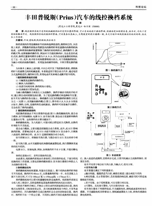
图 3 系统 框 图 换 档位 置 指示灯 。表明 目前换 档位 置 。 由此看 出, 线控换档系统由许多协同工作的部件组成。 下面分析线 位 。 换入前进档或倒档 , 需要两步完成 , 以使司机确认完成换档操作 , 增 控换 档 的工作 原理 , 要包 括换 档模 块 部分 , 车执 行器 部分 和 防止 人 强安全 性。 主 驻 驻车开关用于啮合驻车执行器 , 为触点式, 使用方便。 为误操作部分等。 3换档操纵机构 4驻车执行器 驻车装置应满足下列性能要求 : 换档操纵机构结构紧凑 , 布置在仪表盘 E 整个机构由换档杆和驻 。 a 输出性能。能提供适 当力矩, 车开关组成。 换档杆约 8rm长 , 0 a 比普通换档杆短一半 。 在仪表板上 占 确保在坡道上能分离驻车机构 据不大的空间, 尺寸为 l0 m( ) 5 mm ̄)×10 m( ) O m 宽 ×10 ( 7r 长 。 a b响应陛能。 . 在正常使用时 , 具有很高的响应度, 确保司机可舒适地 换档操纵机构可以使司机能够轻松舒适地换档。线控换档系统完 操纵驻车机构。 c 易 于安装。由于结构紧凑 , 全按 ^ 、 机工程设计 , 其舒适程度是其他类型换档机构无法 比拟 的。 可在有限空间安装。 司机松 开换 档手 柄后 , 手柄会 立 即 自动 回到原 始预定 的位 置 。 档 换 d . 可靠陛。具有高可靠性 , 与汽车使用寿命一致 。 模式也很简单 , 司机很容易记住 。若司机想要换到某个档位 , 不用考虑 驻车执行器有下列部件组成: 开关磁阻电机 、 摆线减速器和转角传 目前的档位 。因为换档操作完成后换档杆会 自动回到初始位置。换档 感器。开关磁阻电机用作驱动力 , 摆线减速器放大力矩, 转角传感器检 时,换档杆只有一个停止位置 ,不用担心换档不到位或换档杆移动过 测 电机转角 。
丰田普锐斯培训资料--诊断
诊断程序
有效的分析方法
1. 客户的操作是否和通常有所不同?
例如: 操作电源模式 IG/ON ? OFF 20 次或更多 (READY ON 便无法实现)
2. 从发现故障时到进厂途中的相关信息
3.发现故障前行驶条件
-有些DTC只有在电源模式OFF时才能检测到
?
?
?
不能驱动
?
SMR OFF (SPD=0)
?
?
高压蓄电池 有问题
?
SMR OFF
?
?
警告灯
?
?
?
?
Rear Motor (MGR)
?
?
故障事例
MG1 控制, 分解器 型传感器
MG2 控制, 分解器 型传感器
?
ECU 内部故障
?
高压蓄电池
?
温度传感器 , 等. (传感器系统 )
失效保护的恢复状态 : 返回到正常状态并且电源模式从 OFF to ON (ACC, IG/ON, READY ON)
定格数据
利用定格数据
1. 它可以被用作故障再现试验,因为它知道在故障被检测到时 行驶和操作的状态。
2. 考虑“故障发生顺序” = 信息中的1表示主要因素
要点!
当把车辆开到车间时,要确认记录定格数据和信息
定格数据
理解时间序列
Item ENG RUN TIME DTC CLEAR WARM
Contents 在一次系统启动中发动机运转的时间 在清除DTCs后系统启动的次数
A, U.V.W. 信号检查
NG NG
MG1 或 2 失 效
B, 变频器电压检查
丰田普锐斯用户手册PriusUserGuide

DRIVING (2)Just Drive It ! (2)Modes (2)Eco-Meter (4)Energy Monitor (6)Consumption (8)Efficiency (10)Trip Info (11)Battery Info (12)Brake Assist (13)Tire Pressure (13)BUTTONS ...................................... 14 Steering-Wheel ........................ 14 Voice ........................................ 16 Cruise ....................................... 16 Dimmer .................................... 16 Timer (PHV) ............................ 17 Cabin Air ................................. 17 Window Defog ......................... 18 Fan Options .............................. 18 Other Buttons ........................... 20 HELPFUL TIPS ............................. 21 Fuel Door ................................. 21 Rear Hatch ............................... 21 Grille Blocking ........................ 22 OTHER ........................................... 23 External Cargo ......................... 23 Security .................................... 25 EDUCATION ................................. 26 Real-World Data ...................... 26 Operational Info ....................... 26 GLOSSARY .. (29)Disclaimer:All the information stated in this document was provided by Prius owners. None were affiliated with Toyota Motor Corporation,except as customers.This document is not sanctioned by Toyota Motor Corporation or any of its affiliates.The ideas, suggestions, and opinions offered in this document have not been endorsed by the manufacturer of those specificcomponents or Toyota Motor Corporation.Any harm or damage that may result from the application of or the following of any ideas, suggestions, or opinions contained inthis document is the sole responsibility of the individual that applied or followed said ideas, suggestions or opinions.The authors of this document hereby declare that they cannot and will not be held liable, in any fashion, for the content or the useof this document.Toyota Prius User-GuideSecond Edition for the 2010-2012 modelsDRIVINGJust Drive It !Vital Info The “Just Drive It” advice still remains good advice. Misconceptions about the technology havebeen dispelled over the years. Yet, some new owners are compelled to drive differently, assumingthat will result in higher efficiency. In reality, there’s nothing special you actually need to do.Just drive it as you would any other vehicle. The system is designed to operate in the mostefficient manner automatically. Enjoy the smooth & quiet operation.ModesChoicesThere are actually 4 available. 3 are activated by pressing the button provided for it. The 4th is the“Normal” mode; it is automatically active when none of the other 3 modes are selected.EV comes in handy when you need more power at slow speeds but would like the engine to remainoff. ECO provides greater play with the accelerator pedal, as well as altering the A/C and Heaterthresholds for more efficient operation. PWR allows you to take advantage of the power thesystem offers.Don’t mistake the buttons for traditional low-gear or over-drive options. The selection choice isthere for you to optimize efficiency and specify pedal preference. Performance itself is not altered.Choices (PHV)Similar to the regular model Prius, the PHV offers 4 operational modes. ECO, PWR, and Normalwork the same. The button unique button is for switching between HV and EV modes.EV allows you to drive up to 62 mph (100 km/h) using only electricity, without the gas engine inmotion. HV is the option available to preserve that EV for use later, since you may want to saveelectricity while on the highway for city driving afterward. EV is available for faster speeds, butthe engine will run in conjunction with the electric motor then, delivering very high MPG as aresult. This automatic mode is referred to as EV-BOOST.ECO ModeThis indicator illuminates when the ECO MODE button is pressed. Vehicle efficiency is directly affected by outside temperature. In both extreme hot and extreme cold driving conditions, you’ll benefit from using this mode. It instructs the hybrid system to operate the A/C in a manner which uses less electricity than normal, when it’s hot. When it’s cold, the window defroster will operate like the A/C and the heater will allow the engine to shut of sooner. Vehicle efficiency is also affected by how you drive. This mode increases the sensitivity of the accelerator-pedal, allowing easier control for opportunities when you wish to adjust acceleration rate. PWR ModeThis indicator illuminates when the PWR MODE button is pressed. When power is needed quickly, using this mode can be beneficial. It prevents the engine from shutting off as soon as it normally would to provide maximum acceleration without delay. Vehicle efficiency is reduced when using this mode, even if you don’t take advantage of the rapid power it can offer. The accelerator-pedal sensitivity is decreased and initial thrust from the electric-motor is noticeably more responsive. So, feel free to indulge at times. The hybrid system will still deliver impressive MPG even in this mode. EV ModeThis indicator illuminates when the EV button is pressed. This mode allows the electric-motor to provide additional thrust without the gas-engine starting. On the Eco-Meter, you’ll see the energy usage exceed the usual GREEN zone threshold, allowing engine-off (zero RPM) driving in both the WHITE and RED zones. The catch is the emissions system must be hot (at least 155°F, 68°C) and speed cannot exceed 24 MPH (39 km/h). If either of the criteria is not met, the EV mode will disengage but the engine may still remain motionless (often referred to as “Stealth ” mode). EV Mode (PHV)The PHV model provides a different indicator above the speedometer to inform when EV MODE is engaged. It will illuminate whenever that mode is selected, even if the engine running for warm-up. Use the indicator above the Eco-Meter to inform you when the gas engine is actually off. The temperature threshold for EV MODE is different in the PHV than the regular model Prius. 130°F (54°C) is what the coolant needed to be warmed to before the engine will shut off, once started for the first time. EV is default, allowing you to run without the engine until it is needed for extra power or for heating the cabin. EV Boost (PHV)When the PHV mode Prius is still in EV mode, but speed of travel exceeds 62 mph (100 km/h), the battery-pack will continue to supply electricity at the more ample rate. You’ll see dramatically higher MPG as a result. When you only have a short distance to travel, this may be a better use of the electricity than switching to HV mode. The toggle button provides the option to choose.Normal When no other indicators lights are illuminated, this is the mode Prius is in.Use this mode for the most average driving experience. All hybrid features will operate within theregular tolerances, providing a nice balance of power & efficiency.Eco-MeterThe “Hybrid System Indicator”, commonly referred to as the Eco-Meter, provides an assortment of information for the driver. This is the source of detailed data not available from the classic “Energy Monitor”, making it the preferred choice after becoming accustomed to how the hybrid system operates. The energy-bar displayed in the center points out the amount energy being consumed & captured in addition to indicating the engine-on threshold.GreenThe first zone is that green area illuminated in the photo of the energy-bar above. It identifies themost efficient vehicle operation. Up to the center dividing line, the engine will remain off. For themode referred to as “Stealth”, driving up to 46 MPH using only electricity indicated by that green.WhiteThe second zone is the white area which follows the green. This indicates when additional poweris being consumed. When EV mode is active, this illustrates the amount electricity being drawn.When beyond the EV mode (24 MPH) or “Stealth” mode (46 MPH) thresholds, this illustrates theamount of thrust contributed by the gas engine.RedThe third zone is the red area. It indicates when high power demand is requested. This specificzone should be used only briefly, to avoid inefficient driving. To make status easier to notice, likeduring hard acceleration, the ECO symbol above the energy-bar disappears with red is active.ChargeWhen electricity is being captured by regenerative braking, the energy-bar will indicate it byilluminating the area with the CHG label. Status will move to the left to illustrate an energy gain,rather than to the right to illustrate energy consumption. The most efficient braking is when theindicator is kept within that zone; exceeding it means some energy is lost by the friction brakes.HV ModeIntroduced with the 2012 models of Prius is the “HV” indicator. This is that car-shaped symbolwhich tells you when in the engine has shut off. When it is only an outline (no EV inside), thatmeans you are driving in HV mode. This stands for “hybrid vehicle”, when both engine & motorare contributing to propulsion needs.EV IndicatorIntroduced with the 2012 models of Prius is the “EV” indicator. This is when that car-shapedsymbol is filled with “EV” inside. This informs you when the gas engine has stopped. In otherwords, it tells you when you are driving with the engine at 0 RPM. This is the mode commonlyreferred to as “Stealth”, since you are still in HV but propulsion is currently electric-only.EV Mode (PHV)Exclusive to the PHV model, there’s a new indicator. This is a larger version of the EV symbol.When illuminated, it informs you that driving is in full EV mode and will remain that way untilhard acceleration occurs or speed exceeds 62 mph (100 km/h).EV Boost (PHV)When traveling at speeds faster than 62 mph (100 km/h) in the PHV while in EV mode, the largerversion of the EV symbol will become just an empty outline. This informs you that electricity isbeing drawn from the battery-pack at a much faster rate than HV mode to provide much higherefficiency. It also tells you that EV will automatically resume when the vehicles slows down.EV Warm-Up (PHV)At any time while in EV mode, the gas engine may start up. This can happen when acceleratinghard, more heat from the coolant is needed to warm the cabin, or simply when warmth is needed forthe emission-system. Like with EV-BOOST, electricity continues to be drawn from the battery-pack at the faster rate and the gas engine will shut off as soon as it is no longer needed. The symbolwill change from that empty online back to EV when warm-up is complete.Energy MonitorThis screen available on the Multi-Information Display is an educational tool for new owners. It provides real-time information about what the hybrid system is doing while you drive. Seeing the variety & frequency of gas engine, electric motor, and battery interactions is a very effective way of understanding how the system achieves such high efficiency.Stealth ModeThe mode, also known as “Battery Drive”, is when all thrust is provided by the electric motor andall power is provided by the battery-pack.RegenerationChargeAs you approach a stop or just slow down, the excess kinetic energy is used to turn the generator.This creates electricity, which is used to charge the battery-pack.Engine & MotorDriveThere are times when the battery-pack isn't needed, the engine will directly provide electricity forthe motor.Engine Drive +ChargeThe engine provides thrust for the wheels along with electricity for charging the battery-pack.Engine & MotorDrive + ChargeThe engine provides thrust to the wheels as well as electricity for both feeding the motor andcharging the battery-pack, all at the same time.Full Power orGradual SlowingBoth rapid acceleration and moderate deceleration take full advantage of the hybrid system toachieve maximum efficiency.Startup Charge orEngine HeatWhen you first startup a Prius, you will typically see this before shifting into drive or reverse. Italso occurs when additional heat is needed.EV Distance (PHV)The PHV model Prius provides EV distance information on the screen. The contents of the batteryappear solid when an ample supply of electricity is still available. That solid will change to barswhen electricity drops to the normal level for HV operation.Charging (PHV)If you press the power button on the PHV model Prius while it is plugged in and charging, thisscreen will be displayed. It tells you how much time is required to complete and at what rate thepower is being drawn from the plug.ConsumptionSeeing the effect recent driving had on efficiency during that specific moment can be quite informative. Two different versions of the consumption are provided for this. They both indicate the MPG during the time-span illustrated and how much (if any) regenerative electricity was recaptured by the braking system. (Note that electricity generated directly by the gas engine is not included.)1 minThis consumption information screen displays the most recent 15 minutes of travel since the hybridsystem was restarted. Each bar indicates a 1-minute span of time.5 minThis consumption information screen displays the most recent 30 minutes of travel since the hybridsystem was restarted. Each bar indicates a 5-minute span of time.HistoryRather than displaying information based upon time, there is an additional consumption screen which provides summaries between resets based upon distance. It also numerically shows the best MPG among individual drives. Two different sets of data can be stored, using the “A ” and “B ” trip-meters. A suggested use for getting the most information from the feature is resetting the start of each morning and each time you refill the tank.History (PHV)The passage of time is more pronounced with the PHV model, making the benefit of month rather than an arbitrary reset of a trip meter quite obvious after you’ve driven one for a while. This is the display screen provide for that purpose. Driving Ratio (PHV)An especially new educational display screen for the PHV model is this EV DRIVING RATIO. There are two resettable meters available. But provide EV and HV summaries. The information gives you an idea of how much benefit you are directly getting from the plug, displacing gallons of gas with electricity.EfficiencyHaving immediate feedback about the results of system operation as it happens is quite empowering. You develop an appreciation for how the design responds to the complexities of real-world driving conditions. It influences your choices about driving. The following are examples of what you’ll find most informative.Stealth ModeWhether or not your Prius has a plug, you’ll often drive in “Stealth ” mode. This is when the gas engine shuts off (stops moving) and travel continues along using only the electric motor, even though you are not driving in EV mode. That “EV” symbol indicates that status. This automatic feature of the hybrid system takes advantage of efficiency opportunities. There’s nothing you need to do to optimize it. In fact, prolonging the engine from starting back up again may lower overall MPG. It’s there as a reminder of how Prius efficiency is achieved.Distance (PHV)Distance of travel has always been an efficiency influence easily overlooked. The introduction of the ability to use plug-supplied electricity makes the topic even more eluding. On the Eco-Meter and Consumption screens, you’ll see TRIP-A and TRIP-B values for MILES and MPG. When trips are really short or really long, you’ll notice a significant efficiency different from trips medium in length. Don’t let that bother you. Remember, you’re still getting a benefit from the electricity regardless of how it’s used. That MPG value clearly shows it.Trip InfoAt the bottom of many of the Multi-Information Display screens, there are numeric values indicating accumulated status of driving results since the previous reset and last refill. This is also how the vehicle distance odometer value can be seen.TripThere are two storage meters available, trip “A” and “B”. Each accumulates separate results.Drivers find this handy for tracking a variety of conditions. You can reset whenever you want…each trip, when the tank is refilled, or just leave it to collect up to 10,000 miles of data.MilesThis indicates how many miles the data represents. It changes back to zero, along with the othervalues displayed, when the TRIP button on the steering-wheel is reset (holding it continuouslyfor 3 seconds).MPGThis value indicates the total consumption of gas by the engine since the previous reset. It is anoverall average representing MPG (miles-per-gallon).AverageAn important aspect of efficiency usually overlooked is the average speed of travel. The hybridsystem continues to operate even if the vehicle is not moving. The resulting amount of gas &electricity consumed can be misrepresented by just the distance in miles alone. This value alsotakes time into account. The MPH (miles-per-hour) value will drop as you sit in daily stop & slowcommute traffic or wait for a light to turn green. It is an overall calculation of the entire durationthe hybrid system was active, to give you a better idea of how overall driving is influenced.EmptyDistance to empty information is also available. This is the third option, following “A” and “B”.The value shown is an estimate of the miles you can continue to travel, based upon current tankefficiency, before you’ll need to refill.Battery InfoLevelThe SOC (state-of-charge) level of the battery-pack is indicated by this illustration on the Multi-Information Display. Only the usable capacity is shown. So even when no bars are visible, there is still electricity available. When all 8 bars are filled, the battery-pack isn’t completely full.6 bars is the most common level. Drivers won’t often see the top two filled. Seeing less than the bottom doesn’t often happen either. The hybrid system attempts to keep the SOC within those 4 middle bars for maximum longevity of the battery-pack.EmptyEmpty is no reason to panic, though new owners sometimes do when the SOC level gets down to just 1 bar. The engine will simply start up to replenish the electricity supply. There is no need to alter the way you drive while that occurs.Remember, that’s actually about 40 percent of the battery-pack SOC remaining, even when only 1 bar is showing.Recharging (PHV)Within the charge-port area on the outside of the Prius is this indicator.If the timer is set, it will immediately illuminate to confirm connection to the charger is complete then shut off shortly afterward. Later when the timer starts charging, this symbol will illuminate again.If the timer is not set, this symbol will immediately illuminate to confirm connection to the charger and remain that way until charging has completed.Full (PHV)When there is an ample supply of electricity available, the symbol for the battery on the various display screens will appear solid like this. As the supply lowers, this image of the battery will too.Below the image of the battery is a rough estimate of the EV distance available stated in terms of miles. Remember, this number will drop faster when acceleration is needed and slower when very little power is needed.Also, the numeric value is based upon recent travel. If you travel long distances with few opportunities to recharge, the miles represented will be lower. If you travel short distance recharging frequently, the miles represented will be higher. It’s only an estimate using observation, which will vary over time, not an indicator of actual battery capacity.Low (PHV)As the supply of electricity reaches the depletion point at which EV will switch over to HV driving, the solid interior of the battery image will change to bars. This is done as a visual convenience; otherwise, all you’d ever see following depletion would be an empty battery.The value will up and down as you continue to drive in HV mode. Sometimes, there will be enough electricity regenerated to change the battery image back to solid. This is normal expected operation.Brake AssistRollbackPreventing vehicle rollback when starting from a start on a hill is very easy with a Prius. It offers a “brake assist” feature.Press very hard on the brake pedal for about 2 seconds. That symbol to the left will illuminate, informing you that the vehicle will remain in place for a few seconds while you shift your foot from the brake to the accelerator. When acceleration begins, the brake will automatically release.Tire PressureWarningLow tire pressure is very dangerous, so much so that a federal mandate was issued for all automakers to provide a warning to indicate when the PSI has dropped 25 percent below the recommended minimum.35 PSI front and 33 PSI rear is the recommended minimum by Toyota.44 PSI front and 42 PSI rear is what owners wanting higher efficiency and longer treadlife use.BUTTONSSteering-WheelRight ClusterOn the right side of the steering-wheel, there is a cluster of 5 multi-use buttons available. Using each is just a matter of pushing one with your thumb. Note that the orientation of the buttons changed from side-side to up-down with the 2012 models.Climate-Control adjustments and options for the Multi-Information Display screens are what this cluster offers.TripUse this button to alternate trip information between “A” and “B” and Distance-To-Empty.DispUse this button to choose a screen on the Multi-Information Display next to the speedometer.LowerFor a lower climate-control temperature, push this button.Continuing to hold this button will cause the temperature to decrease until you release.HigherFor a higher climate-control temperature, push this button.Continuing to hold this button will cause the temperature to increase untilyou release.RecirculateThe benefit of this button often misunderstood. When recirculate is active, fresh air from outside is not used. Instead, the interior air is continuously passed through the heating or cooling system. Doing this allows quicker cabin comfort, but will eventually led to a humidity build up since your own breath contributes moisture to the air. So, limit the use of this feature.This button makes it convenient to toggle recirculate on & off.Left ClusterOn the left side of the steering-wheel, there is a cluster of 5 multi-use buttons available. Using each is just a matter of pushing one with your thumb. Note that the orientation of the buttons changed from side-side to up-down with the 2012 models.Audio-System selections are what this cluster offers.ReduceUse this button to reduce the volume of the audio-system.IncreaseUse this button to increase the volume of the audio-system.PreviousTo select the previous audio-track or radio-channel, push this button.Holding this button down for a moment will cause the multi-CD player to switch to the previous disc.NextTo select the next audio-track or radio-channel, push this button.Holding this button down for a moment will cause the multi-CD player toswitch to the next disc.ModeTo change among the audio-system choices (AM, FM, SAT, CD, AUX), use this button.Pressing this button when the audio-system is off will cause it to turn on.Holding this button when the audio-system is on will cause it to turn off.VoiceNavigationCommands issued verbally to the navigation system start by pressing this button.PhoneWhen a cell-phone is connected via bluetooth, the sides of this rocker-switch can be used to answer a call and hang-up afterward.Pushing the BOTTOM will make the phone dial-pad appear on the Multi-Information Display.Pushing the TOP will return the Multi-Information Display to the screen it was on prior to the phone call.CruiseRadarFor models of Prius equipped with dynamic cruise-control, this is the button to adjust the detection-distance for the radar system.Pushing it repeatedly will toggle you through the distances available, which will be illustrated on the Multi-Information Display.DimmerBrightnessThis button (actually an adjustment knob) allows you to dim or brighten the speedometer cluster. Rotating it all the way is how you switch between day & night mode.It’s location is low on the dashboard, to the left of the steering-wheel.Timer (PHV)StartUnique to the PHV model is the timer button. Pressing this displays the screen for scheduling adelayed charge start. You can do this at any time, including after having pressed the power buttonto shut off the Prius.Using this button allows you to take advantage of lower electricity rates during off-peak hours. It’salso beneficial for battery longevity to wait before charging again. Delaying recharge to let thebattery cool down after use is called a “cold soak”. The timer button makes this easy.There are 2 timer options available. The photo shown above is the START option; charging willstart at the time specified. There is also an END option; charging will start 3 hours prior to thattime specified.Cabin AirRecirculatePressing the LEFT side of this rocker-switch causes the air-conditioning system to circulate insideair throughout the passenger-cabin. This is handy for retaining hot or cold air, but will also retainmoisture from your breathing which will eventually cause the windows to fog.When using the toggle button on the steering-wheel, the indicator light will alter accordingly.OutsidePressing the RIGHT side of this rocker-switch causes the air-conditioning system to draw fresh airfrom outside to circulate throughout the passenger-cabin. Use this mode to avoid window fogging.When using the toggle button on the steering-wheel, the indicator light will alter accordingly.Window DefogFrontWhen the FRONT window becomes fogged and the regular blower is not enough to clear it, press this button. All air-conditioning blowing will be forced through the window-vents for maximum effectiveness.This feature is commonly referred to as the “defroster”.RearWhen the REAR windows become fogged, push this button to activate the electric warmer (those metal wires attached to the glass) to clear them. This will also melt any snow that has accumulated on the outside of the winter.This feature is commonly referred to as the “rear defroster”.Fan OptionsModeTo adjust the fan speed, use this rocker-switch to make it faster or slower.Also, pressing either side of this when the blower fan off will turn it on.BlowerThis illuminated display shows what speed the blower fan is set to.Note that in some circumstances heating can be more effective if the speed isn’t maximum, since slower air passing through theheater-core can transfer more warmth.ModeTo shift among the 4 fan options available, use this button.For easy adjusting, keep in mind that there are 4 to choose from. Remembering that allows you toggle without the need to look at the display to confirm the choice. This comes in handy when swapping the “Window + Upper” and “Lower + Upper”, a common need during the winter. Just press MODE twice.Window + LowerFor a normal level of window clearing and air blowing out the vents at your feet, use this mode.LowerFor air blowing only out the vents at your feet, use this mode.The vents for this are located at the base of the dashboard for the front seats and underneath the front seats for those sitting in back.Upper + LowerFor air blowing out both the vents at your feet and the vents at chest level, use this mode.UpperFor air blowing only out the vents at chest level, use this mode.。
转 详解丰田普锐斯 Toyota Prius 工作模式
通过观察这个示意图,可以看到动力分配器由一个中心齿轮、四个小的行星齿轮、一个圆形的行星齿轮座、一个外齿圈构成。
对汽油机来说,每分钟1000转的启动转速实在算不了什么,因为汽油机本来就能靠自己的力量以这个速度从容运转。另外,普锐斯启动时只给2个汽缸点火,这就使得汽油机启动非常平稳和宁静,避免了普通汽油机的启动磨损。
汽油机启动完成后,普锐斯的车载计算机会控制汽油机节气门的开度,以保持预热时的合理怠速。这时,电池组不再向一号电机供电,如果电池组电量不足,反而可以利用一号电机发电来给电池组充电。为此,车载计算机只需将一号电机切换到发电状态(正转)并将汽油机节气门开大一点即可将电力导出。
2、冷车启动
普锐斯的汽油机冷车启动后,会运转一会儿,主要是给汽油机和催化剂转换器预热,使废气排放控制系统开始工作。具体运转多长时间取决于汽油机和催化剂转换器的实际温度。冷车启动以后,汽油机怠速为每分钟1300转。
3、热车启动
普锐斯热车启动时,汽油机转一会儿就会停下来。汽油机怠速略低于每分钟1000转。
行星齿轮本身没有动力源,但它们有“自转”和“公转”。行星齿轮在短轴上的旋转为自转,自转可以是正转,也可以是反转;公转是指四个行星齿轮随“行星齿轮座”一起围绕恒星齿轮公转。
四个行星齿轮虽然没有动力源,但却有特别的功效。正是由于它们的存在,才使行星齿轮座、恒星齿轮和齿圈之间的微妙相互作用成为可能。譬如,当齿圈固定不动(即普锐斯车轮静止不动)时,有了行星齿轮的自转,恒星齿轮(暨一号电机)才可以带动行星齿轮座(即汽油机)转动;有了行星齿轮的自转,当齿圈(暨二号电机)正转时,恒星齿轮(即一号电机)才可以反转,而当齿圈(暨二号电机)反转时,恒星齿轮(暨一号电机)又可以正转。又如,当齿圈和恒星齿轮以某个速度同向转动时,行星齿轮可以不转,造成行星齿轮座的公转,从而带动汽油机转动。当行星齿轮座不转(相当于发动机停转)时,齿圈和恒星齿轮仍可以自由转动,等等。总之,有了这个行星齿轮组,发动机与车轮及电动机之间就可以始终保持联接了,也就不需要离合器了。理解动力分配器的工作状态需要一点想像力。
2009年丰田普锐斯(PRIUS)底盘培训课件
E发n动gin机e
Ch底as盘sis
Bod车y 身Ele电ct气rical
-A -K -W -Q
复合齿轮机构 –每一个行星齿圈与复合齿轮机构结合。 –此外,复合齿轮机构与中间轴主动齿轮和驻车齿轮结合。
驻车车锁止齿轮 齿圈 (电机减速行星组件)
动力分配行星组件
中间轴主动齿 轮
齿圈(动力分配行星组件) 电机减速行星组件
从P
驾驶员换入B档
从R
从N
拒绝后的档位 保持在P档 换入N档 换入N档
保持在P档 换入N档 保持在N档
18
Mo车de型l O概u述tline for注T意ec事hn项ician Hyb混ri合d S动y力stem
电子换档系统
E发n动gin机e
Ch底as盘sis
Bod车y 身Ele电ct气rical
于发动机冷却系统
HV 散热器
变频器
HV散热器储液罐
变频器
HV 散热器储液罐 HV 电机水泵 HV 变速驱动桥
HV 散热器
HV 电机水泵
12
Mo车de型l O概u述tline for注T意ec事hn项ician Hyb混ri合d S动y力stem
电子换档系统
E发n动gin机e
Ch底as盘sis
Bod车y 身Ele电ct气rical
混合驱动桥注油塞
(10 mm 六角螺栓)
Ch底as盘sis
Bod车y 身Ele电ct气rical
-A -K -W -Q
Front
混合驱动桥放油塞
(10 mm 六角螺栓)
冷却液排放塞 (10 mm 六角螺栓)
10
Mo车de型l O概u述tline for注T意ec事hn项ician Hyb混ri合d S动y力stem
- 1、下载文档前请自行甄别文档内容的完整性,平台不提供额外的编辑、内容补充、找答案等附加服务。
- 2、"仅部分预览"的文档,不可在线预览部分如存在完整性等问题,可反馈申请退款(可完整预览的文档不适用该条件!)。
- 3、如文档侵犯您的权益,请联系客服反馈,我们会尽快为您处理(人工客服工作时间:9:00-18:30)。
Sub Bus Line Sub Bus Line
CAN Communication
Terminal Circuit
: : : : CAN CAN CAN CAN Main Bus Line (High) Sub Bus Line (High) Main Bus Line (Low) Sub Bus Line (Low)
Exit Utility
Steering Angle Sensor
Skid Control ECU
CAN Communication
Bus Check • Both ECU’s and sensors on CAN have selfdiagnosis and communication function
CAN Communication
Feature • Communication Frame – Same as BEAN communication, all CAN nodes (ECUs, sensors) communicate with bit signal
Address for Receiver ECU Data Type End Message Response of Receive ECU
Communication System
— CAN —
Multiplex
CAN Communication
General • What is CAN ? – CAN is an acronym that stands for Controller Area Network. – CAN is a serial communication protocol developed by BOSCH in 1986 and standardized by (International Standards Organization) Advantage of CAN
Regular (ms)
24 – 32 32 – 64 12 – 24
Event
None
Approx. 500 – 5000
with
NOTE: BEAN: 50 – 1000 ms (250, 500, 1000)
CAN Communication
Inspection Procedure • Two methods to check bus communication 1. IT-II Tester 2. DVOM
c
Powertrain Engine and ECT Laser Cruise CCS
Bus Check * : See Help
Touch!
*
DTC
Data List
View
Active Test
Utility
CAN Communication
Bus Check • Bus Check Procedure (Communication Malfunction DTC)
CAN Communication
Feature • Communication Wire – CAN uses twisted-pair wire
CAN [Differential Voltage Drive] BEAN [Single Wire Voltage Drive]
Hi
ECU
Hi
ECU ECU ECU
: : : :
CAN CAN CAN CAN
Main Bus Line (High) Sub Bus Line (High) Main Bus Line (Low) Sub Bus Line (Low)
Engine ECU (ECM)
EPS ECU
DLC3
Skid Control ECU
Steering Angle Sensor
Control Protocol*1
Driving Control System CAN (ISO Standard)
Body Electrical Control System BEAN (TOYOTA Original) Max. 10 kbps AV signal Drive Single Wire Voltage Drive 1-11 Byte (Variable) AVC-LAN (TOYOTA Original) Max. 17.8 kbps Twist Pair Wire Differential Voltage Drive 0-32 Byte (Variable)
Enter DTC Data List View Active Test
Exit Utility
CAN Communication
Bus Check • Check communication with ECU’s and sensors
Engine ECU (ECM)
Yaw Rate Sensor Deceleration Sensor
• High Speed Communication of large volume data • Reduce amount of wire harness • Reliable Transmission
CAN Communication
Feature • Communication Speed – High-speed communication (ISO 11898)
DLC3
Function
Bus Check System
View
System
Bar
Help
Current OK OK 1 OK OK OK
Engine and ECT Air Suspension ABS/VSC Laser Cruise Air Conditioner Immobiliser SRS Airbag Gateway Body No.2 Body No.4 Body No.5 < Back DTC Data List Details Next > View Active Test
Function
Bus Check
View
System
Bar
Help
Communication Bus Check Detect all ECUs which are connected to the communication Bus.
Touch!
Communication Malfunction DTC Diagnose DTCs which relate to the communication.
1. Bus Check 2. CAN Bus Line Check
Function
Bus Check System
View
System
Bar
Help
Current OK OK 1 OK OK OK
Engine and ECT Air Suspension ABS/VSC Laser Cruise Air Conditioner Immobiliser SRS Airbag Gateway Body No.2 Body No.4 Body No.5 < Back DTC Data List Details Next > View Active Test
0V
Time
CAN Communication
Terminal Circuit • With faulty resistor
Yaw Rate Sensor Deceleration Sensor Engine ECU (ECM)
3.5 V
2.5 V
Skid Control ECU
0V
Time
CAN Communication
EPS ECU Battery ECU
Yaw Rate Sensor Deceleration Sensor
Engine ECU (ECM)
Junction Connector
Terminal Circuit
Terminal Circuit
DLC3
Skid Control ECU
Steering Angle Sensor
Location
Gateway ECU HV ECU Engine ECU J/C No. 2
EPS ECU J/C No. 1
பைடு நூலகம்
Yaw Rate and Deceleration Sensor
Skid Control ECU
Steering Angle Sensor DLC3 Battery ECU
Exit Utility
CAN Communication
Bus Check • Bus Check Procedure (Communication Bus Check)
Function
View
System
Bar
Help
System Select The following vehicle profile was found. LS430 /UCF / 03MY / 3UZ-FE
Lo
Lo
Twisted-pair Wire
AV Single Wire
CAN Communication
Feature • Communication signal
[CAN HI]
3.5 V
2.5 V
0V
Time
[Output Voltage]
[CAN LO]
2.5 V 1.5 V Time CAN HI
Header Data Length
