(爬行器英文)使用说明书
超声波检测工业超声波爬行器 - 小管焊接说明书

S up er Id ea fo r U ltr as on ic In sp ec tionIndustrial Ultrasonic CrawlersCrawler for Small Pipe Welds●Compact, lightweight, portable, waterproof and rust-free. ●Probes and wedges can be quickly and easily changed.●Support up to two phased array probes to cover the whole welds at one time.●Covers standard pipes with outside diameters ranging from 20.32-114.3mm (0.84-4.5 inch).●Can be operated within 15mm clearance, perfect for hard-to-reach area inspection. ●Encoder precision: 32.6step/mm●The probe spacing can be adjusted in the range of 0-55 mm.●Crawler can provide stable and constant pressure around the pipe full circumference.●Urethane wheels help the crawler have smooth radial movement along the pipe and reduce axial drift.●Positive inspection and reverse inspection with high reproducibility and good coupling.●With its simple buckle design, just easily buckle up and unbuckle the links for different pipe diameters (No need to disassemble the whole scanner).●Two inspection methods: one-side inspection and dual-side inspection.The Phased Array low profile crawler LPS-01 and LPS-02 are compatible with Phased Array ultrasonic flaw detector, which is used to perform circumferential weld inspection on small diameter pipes.●Dual-side inspection is suitable for covering the whole welds at one time of pipe-to-pipe inspection.●One-side inspection is suitable for elbow, pipe tee and pipe cap of pipe-to-component inspection/LPS-02LPS-01ConfigurationTypical configuration for dual-side inspection: LPS-02 crawler, two R35E phased array probes with 60°refraction angle AOD wedges, Y splitter, SIUI phased array flaw detector and manual irrigation device.Low-profile Phased Array ProbePhased Array Wedge●Note: SIUI low-profile probes and wedges are compatible with Cobra from Olympus and Circ-it from Jireh. Technical SpecificationFoldable Phased Array & TOFD CrawlerManual PA and TOFD CrawlerSuperior FeaturesStandard configured as two channels TOFD crawlerSupport Phased Array probesSupport up to 3 pairs of probe holders simultaneously.The magnetic wheels can be attracted to the tested work piece for easy operation.Spring guide way structure, which follows the tested surface, maintaining good coupling between the wedge and the tested work piece.The Phased Array and TOFD crawler UHTS-X02 is compatible with PA or TOFD ultrasonic flaw detector. It can be folded in the center for longitudinal weld and unfolded for girth weld, enabling the crawler have better coupling stability to work on smaller pipes, suitable for PA or TOFD testing on plates , girth weld outside the pipe(diameter no less than 500mm) and longitudinal weld outside the pipe (diameter no less than 600mm).The Phased Array and TOFD crawler UHTS-X02 has up to six combinations to meet different application requirements.Encoder Probe HolderMagnetic WheelFoldable StructureApplicationUHTS-X02 crawler is compatible with flaw detector SUPOR to have simultaneous PA & TOFD inspection, which can greatly increase scanning coverage and provide multiple judgment methods to avoid misjudgment.Simultaneous Inspection of PA & TOFD VideoTo know more, scan QR code.Work with one pair of Phased Array probes for phased array testing. Combination 5 (Two PAUT probes+1-channel TOFD)Work with one pair of Phased Array probes and one pair of TOFD probes for phased array and TOFD testing. Combination 6 (Two PAUT probes+2-channel TOFD)Work with one pair of Phased Array probes and two pairs of TOFD probes for phased array and TOFD testing. Superior Features*The six combinations support irrigation wedges and non-irrigation wedges.Technical ParametersCompact Phased Array & TOFD CrawlerManual PA and TOFD CrawlerThe Phased Array and TOFD crawler PTS-P05 is compatible with PA or TOFD ultrasonic flaw detector. It is suitable for phased array or TOFD testing on plates and pipe workpieces.coupling between the wedge and the tested work piece.of various specifications to meet specific needs.Long probe holder arm and short probe holder armLong beam and short beamTurning Arm Adjustment Superior FeaturesThe Phased Array and TOFD crawler PTS-P05 has up to three combinations to meet different application requirements.*The three combinations support irrigation wedges and non-irrigation wedges.Superior FeaturesPTS-P05 crawler is working with one large-size linear array probeto achieve linear scan on flat panel engraved with SIUI logo.PTS-P05 crawler is working with two phased array probes toachieve multi-group scanning function to inspect from both sidesof the weld, therefore enhancing the inspection efficiency andspeed.Probe holder can be installed in both side of crawler beam to achieveflexible scanning direction.Build-in encoder: compact size and water-proofPTS-P05 crawler is working with 1-ch TOFD probes to achieveTOFD inspection on 48mm thick vessel.PTS-P05 crawler is working with one PAUT probe to achieve phasedarray inspection on weld.Technical ParametersMini Phased Array CrawlerManual PA CrawlerSuperior FeaturesPhased Array crawler PES-02 is compatible with different wedges to inspect butt weld and plates.Phased Array crawler PES-02 is compact, flexible and easy to operate.It is suitable for phased-array single probe (with wedge) to perform ultrasonic phased-array testing on girth weld or longitudinal weld of flat butt welds, pressure vessels or pipes (diameter > 60mm).Waterproof (IP68)Compact sizeAluminum alloy construction:withstand the harshest environments. High encoder resolution: 19.2 stpes/mm .Compatible with long and short pivot arms to achieve flexible application.Butt Weld InspectionPipe InspectionSuperior FeaturesTwo direction wheel assemble methods to achieve horizontal welding and longitudinal welding inspectionTechnical ParametersPivot ArmPES-02 crawler structurePES-01Smaller size to make it perfect for accessing limited spacePES-02Manual TOFD CrawlerSuperior FeaturesThe TOFD crawler TSB-1-P05 and TSB-2-P05 are compatible with TOFD ultrasonic flaw detector as well as TOFD wedges. They are suitable for TOFD testing on plate-type work pieces.The magnetic wheels can be attracted to the workpiece for easy operation.Spring guide rail structure, which enables the probe holder to move up and down along the tested surface, maintaining good coupling between the wedge and the tested work piece.The rolling direction of the wheels is adjustable for transverse scan andvertical scan.TSB-1-P05 (1-ch TOFD)TSB-2-P05 (2-ch TOFD)Technical ParametersSIUI can provide two kinds of irrigation device: auto irrigation device and manual irrigation device.One set with one 3m polyurethane output tube and one valveOne set with one water pump, one filter, 2m input tube, 5m output tube, one adapter and one power supplyAdd: #77, Jinsha Road, Shantou 515041, Guangdong, ChinaTel:+86-754-88250150 Fax:+86-754-88251499E-mail:************* Website:Specifications and appearance are subject to change without prior notice.DCY2.791.Crawler.CY/6A05。
HR-2管道爬行器操作说明书

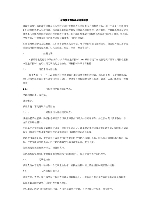
HR-2管道爬行器操作说明书射线管道爬行器是在管道敷设工程中对管道对接焊缝进行全向X光片拍摄的设备。
用一个牵引小车将周向X射线探伤机带入管道内部,当射线机的射线发射窗口对准焊缝位置时,通过遥控,使射线机按照设定的曝光电压和曝光时间对管道对接焊缝进行曝光。
由于采用周向X射线探伤机在管道内部中心曝光,焦距短、单壁投影,一次曝光即可完成整道焊口的曝光,同定向射线机在外部双壁投影的方法相比,工作效率能够提高几十倍。
爬行器在管道内部的运动,由管道外部的指令源或无线电控制箱进行控制,以完成前进、后退、停止、曝光等动作。
2控制方法X射线管道爬行器必须由操作人员在外部进行控制,TSC系列管道X射线管道爬行器可以用同位素指令源进行控制,也可以用无线电的方法控制,两种控制方法各有利弊。
2.1同位素指令源控制操作人员手持一个100毫居以下的放射源对准管道需要控制的位置,爬行器上有一个射线传感器,当射线传感器接收到指令源发出的信号以后,按照指令源控制时间的长短进行前进、后退、曝光等一些列操作。
2.1.1同位素指令源控制的优点:电路相对简单、成本低。
容易维护。
操作方便、不受现场焊接的影响。
2.1.2同位素指令源控制的缺点:设备购置手续繁琐,购买指令源需要省级以上环保部门开具的准购证原件,并且要付费(费用各省、市、自治区有所差别)。
使用单位必须要有同位素使用许可证、辐射安全许可证,购买时还要签订放射源回收合同,购买后必须要有专门的具有红外和监视器等保安设施以及双门双锁的放射源库存放。
异地使用必须备案,指令源到外省市使用的需要先向使用地环保部门备案,经备案后到移出地环保部门备案,异地实用活动结束后,同样到两地的环保部门注销备案,费用不菲。
使用现场必须要有防护标志,设置隔离带。
山区或坡段使用时由于爬行器的惯性运动不能准确定位,容易导致半黑半白的废片。
2.2无线电控制操作人员在管道的一端操作一个无线电控制箱,直接按动控制箱上的按钮控制爬行器的运行。
GMK6220 全地面大容量悬架爬行抬杆机商品说明书

Working range44 - 197 ft.(13.5 - 60 m)138,800 lbs.(63,000 kg)100%360°Boom44 ft.- 197 ft.(13.5 m - 60 m) six section, full-power boom with patented “twin-lock”boom pinning system. Maximum tip height:207 ft.(63 m).Boom ElevationSingle lift cylinder with safety valve provides boom angle from -1.5°to +82°.Lattice Extension43 ft.- 72 ft.(13 m - 22 m) lattice swingaway exten-sion.Hydraulically offsettable 5°- 40°with hydraulic luffing.*Optional Lattice Jib ExtensionTwo 26 ft.(8 m) inserts for use with lattice swingaway extension to increase length up to 98 ft.(30 m) or 125 ft.(38 m).Hydraulically offsettable 5°- 40°with hydraulic luffing.Load Moment & Anti-Two Block SystemLoad moment and anti-two block system withaudio/visual warning and control lever lockout pro-vides electronic display of boom angle, length, radius, tip height, relative load moment, maximum permissi-ble load, load indication and warning of impending two-block condition.CabAll aluminum construction cab is tiltable (approximate-ly 20°) and includes safety glass and adjustable oper-ator’s seat with hydraulic suspension.Other features include engine dependent hot water heater, armrest integrated crane controls, and ergonomically arranged instrumentation.Swing3 swing gears with axial piston fixed displacement motors provide swing speed of 0 - 1.7 RPM thru plan-etary gear box.Also provided is a spring applied, hydraulically released automatic swing brake withfoot-operated release for free swing. Counterweight138,800 lbs.(63 000 kg) consisting of various sec-tions with hydraulic installation/removal system (see counterweight configuration on page 12).EngineCummins 6BTA5.9-C, diesel, 6 cylinders, water-cooled, turbocharged, 165 HP(123 kW) at 2000 rpm. Max.torque:538 ft.lbs.(730 Nm) at 1500 rpm. Engine emission:EUROMOT/EP A/CARB (off high-way).Fuel Tank Capacity53 gal.(200 L).Hydraulic system3 separate circuits, 2 axial piston variable displace-ment pumps, with electronic power limiting control and 1 axial piston variable displacement pump for swing.Standard thermostatically controlled oil cooler keeps oil at optimum operating temperature.Tank capacity:259 gal.(980 L)Control systemFull electronic control of all crane movements is accom-plished using electrical control levers with automatic reset to zero.Controls are integrated with the LMI and engine management system by CAN-BUS.HoistMain and auxiliary hoist are powered by axial piston variable displacement motor with planetary gear and brake.“Thumb-thumper”hoist drum rotation indicator alerts operator of hoist movement.Main AuxiliaryLine length:984 ft.755 ft.(300 m)(230 m)Rope diameter:22 mm22 mmLine speed:426 ft./min.426 ft./min.Line pull:21,000 lbs.21,000 lbs.(93.4 kN)(93.4 kN) Electrical system24 V system with three-phase alternator 28 V/80 A, 2 batteries 12 V/170 Ah.*Optional equipment*Engine-independent hot water heater, with engine pre-heater*Second spotlight*Stereo/cassette player*Air ConditioningSuperstructure specifications* Denotes optional equipmentChassisBox-type, torsion resistant frame is fabricated from high-strength steel.Outrigger SystemHydraulic two-stage outrigger beams are extended by a single hydraulic cylinder and two cables.Outriggers can adjust to two positions:Fully extended (100%) - 27’11”(8.5 m)Partially extended (50%)- 19’8 “ (6 m)Four 29.5 in.x 32 in.(750 mm x 810 mm), self stowing, steel outrigger pads provide rigid lifting base. Outrigger controls are located on both sides of the carrier.An electronic level indicator is located next to each outrigger control box.EngineCummins N14-525 E+, diesel, 6 cylinders, water-cooled, turbocharged, 525 HP (392 kW) at 2100 rpm. Max.torque:1850 ft.lbs.(2509 Nm) at 1200 rpm. Engine emission:EUROMOT/EP A/CARB (on highway).Fuel Tank capacity132 gal.(500 L).TransmissionAllison automatic CLT 755, 5 forward and 1 reverse speed.Transfer case with 2 speeds and inter-axle differential lock.Drive/Steer12 x 8 x 12.Axles6 axles.1, 2, 4 and 5 are drive/steer.Axles 3 and 6 are steer only.SuspensionGMK6220 features the Grove exclusive MEGATRAK†suspension.This revolutionary design features an independent hydroneumatic system with hydraulic lockout acting on all wheels.The suspension can be raised 6-1/2”(170 mm) or lowered 5”(130 mm) both longitudinally and transversely and features an automatic leveling system for on-highway travel.Tires12 tires, 20.5 R25.SteeringDual circuit steering system is hydraulic power assisted with a transfer case mounted, ground driven, emergency steering pump.Axles 1, 2, 3, 5 and 6 steer on highway.Separate steering of the 4th, 5th and 6th axle for all wheel steer and crab-steer is controlled by an electric rocker switch.BrakesA dual circuit air system operates on all wheels with a spring-applied, air released parking brake acting on axles 2, 4, 5 and 6.An air dryer is fitted to remove moisture from the air system.Auxiliary exhaust brake and constant throttle brake is standard.CabTwo-man, aluminum construction driver’s cab includes the following features:safety glass;driver and passenger seats with hydraulic suspension, engine-dependent hot water heater, complete instrumentation and driving controls.Electrical system24 V system with three-phase alternator 28 V/80 A,2 batteries 12 V/170 Ah.Maximum Speed48 mph (77km/h) with 20.5 R25 tires. Gradeability (theoretical)46% with 20.5 R25 tires.Miscellaneous standard equipment Boom removal kit;trailing boom kit (less dolly);additional hydraulic oil cooler;spare tire and wheel - 20.5 R25 with carry bracket;flashing amber warning light on carrier cab;working light;tool kit;fire extinguisher;rooster sheave;radio cassette in carrier cab.* Optional equipment* Electric driveline retarder* 16.00 R25 tires (vehicle width 9 ft.10 in.[3 m])* 14.00 R25 tires (vehicle width 9 ft.9 in.[2.98 m])* Outrigger pressure measurement devices* Folding bunk bed in carrier cab* Engine-independent hot water heater, with engine pre-heater* Third seat* Trailing boom “boost”weight transfer kit* Air conditioning* Mercedes-Benz enginesCarrier specifications* Denotes optional equipment121 - 197 ft.(36,8 - 60 m)43 - 125 ft.(13 - 38 m)138,800 lbs.(63,000 kg)100%AXIS OF ROTATIONFEET102030405060708090100110120130140150160170180190200210220230240250102030405060708090100110120130140150160170180190200210220230240250260270280290300310320330340FEETWorking RangeRated Lifting CapacitiesIMPORTANT NOTES:WARNING:THIS CHART IS ONL Y A GUIDE. The notes below are for illustration only andThe individual crane's load chart,operating instructions and other instruction plates must be read and understood prior to operatingthe crane.1.All rated loads up to 420,000 pounds meetT esting and development were performed to SAEJ1063, Cantilevered Boom Crane Structures -Method of T est and SAEJ765 Crane Stability Test Code.2.Capacities given do not include the weight of hook blocks, slings, auxiliary lifting equipment and load handling devices.to the load to be lifted.When more than minimumshall be considered part of the load.3.surface.a larger bearing surface.4.When either boom length or radius or both are between values listed, the smallest load shown at boom length shall be used.5.operating the boom or lifting loads.† Comparative RatingA rating designation based upon the premise that large capacity European cranes are typically pur-chased and used as long boom, high reach, long radius lift cranes not as heavy lift cranes.To provide a GMK 6220 crane with the necessary equipment to achieve maximum lift capacity will drastically reduce long boom performance.for buyers who require such capacities.Distributed By:Constant improve me nt and e ngine e ring progre ss make it ne ce ssary that we reserve the right to make specification, equipment, and price changes without notice. Illustrations shown may include optional equipment and accessories and may not include all standard equipment.Form No.: GMK6220Part No.: 3-1310 699-10M Printed in U.S.A.Grove Worldwide – World Headquarters 1565 Buchanan Trail East P .O.Box 21Shady Grove, Pennsylvania 17256, U.S.A.T el:[Int + 1] (717) 597-8121Fax:[Int + 1] (717) 597-4062Western Hemisphere, Asia/Pacific Grove Europe Limited*Sunderland SR4 6TT, England T el:[Int + 44] 191 565-6281Fax:[Int + 44] 191 564-0442Europe, Africa, Middle East Deutsche Grove GmbH Sales and ServiceHelmholtzstrasse 12, Postfach 5026D-40750 Langenfeld, Germany T el:[Int + 49] (2173) 8909-0Fax:[Int + 49] (2173) 8909-30Wilhelmshaven WorksIndustriegelande West, Postfach 1853D-26358 Wilhelmshaven, Germany T el:[Int + 49] (4421) 294-0Fax:[Int + 49] (4421) 294-301Grove Asia/Pacific - Regional Office 171 Chin Swee Road #10-09 San Centre Singapore 0316T el:[Int + 65] 536-6112 Fax:[Int + 65] 536-6119 Asia/Pacific, Near East*Grove Europe Limited, Registered in England,Number 1845128, Registered office, Crown Works,Pallion, Sunderland, Tyne & Wear, England SR4 6TTGrove China - Representative Office Beijing Hotel Room 6074No.33 East Chang An Avenue Beijing, 100004, ChinaTel:[Int + 86] (10) 513-7766Fax:[Int + 86] (10) 513-7307Grove Middle East P .O.Box 290Dubai, United Arab Emirates Tel:(Int + 971) (4) 378400Fax:(Int + 971) (4) 373660Lifetime Customer Support Western Hemisphere, Asia/Pacific 1086 Wayne AvenueChambersburg, Pennsylvania USA Tel:[Int + 1] (717) 263-5100Fax:[Int + 1] (717) 267-0404Europe, Africa, Middle East Sunderland SR4 6TT, England Tel:[Int + 44] 191 565-6281Parts Fax:[Int + 44] 191 510-9242Service Fax:[Int + 44] 191 510-9560。
5类爬行卡使用说明

5类爬行卡使用说明英文回答:Introduction to 5 Types of Crawling Cards.Crawling cards are a popular tool for outdoor enthusiasts and adventurers. They provide a convenient and efficient way to traverse difficult terrains, such as steep slopes, muddy trails, and rocky surfaces. In this article, we will introduce five different types of crawling cards and provide instructions on how to use them effectively.1. Basic Crawling Card.The basic crawling card is the most common type and is suitable for general outdoor activities. It consists of a sturdy platform with gripping mechanisms on the underside. To use the basic crawling card, simply place it on the ground and step onto it with one foot at a time. The gripping mechanisms will provide traction and preventslipping, allowing you to crawl forward easily.2. Advanced Crawling Card.The advanced crawling card is designed for more challenging terrains, such as icy slopes or loose gravel. It features additional spikes or cleats on the gripping mechanisms to enhance traction. To use the advanced crawling card, follow the same steps as with the basic crawling card, but be sure to apply more pressure on each step to engage the spikes or cleats effectively.3. Waterproof Crawling Card.The waterproof crawling card is specifically designed for water-related activities, such as river crossings or swamp exploration. It is made of waterproof materials and has enhanced gripping mechanisms that are resistant to water. To use the waterproof crawling card, step onto it as you would with the basic crawling card, but be mindful of the water depth and current to maintain balance and stability.4. Lightweight Crawling Card.The lightweight crawling card is ideal for hikers or backpackers who prioritize weight reduction. It is made of lightweight materials, such as carbon fiber or aluminum alloy, which makes it easy to carry during long-distance treks. To use the lightweight crawling card, follow the same steps as with the basic crawling card, but enjoy the added benefit of reduced weight on your gear.5. Multi-functional Crawling Card.The multi-functional crawling card is a versatile option that combines various features from the previous types. It may include built-in compasses, emergency whistles, or even foldable designs for easy storage. To use the multi-functional crawling card, familiarize yourself with its additional features and follow the instructions provided for each specific function.Conclusion.Crawling cards are valuable tools for outdoor enthusiasts, providing stability and traction in challenging terrains. By understanding the different types available and their specific features, you can choose the most suitable crawling card for your needs. Remember to always prioritize safety and follow the manufacturer's instructions for optimal usage.中文回答:5类爬行卡使用说明。
射线管道爬行器使用说明书
射线管道爬行器使用说明书射线管道爬行器是在管道敷设工程中对管道对接焊缝进行全向X光片拍摄的设备。
用一个牵引小车将周向X射线探伤机带入管道内部,当射线机的射线发射窗口对准焊缝位置时,通过遥控,使射线机按照设定的曝光电压和曝光时间对管道对接焊缝进行曝光。
由于采用周向X射线探伤机在管道内部中心曝光,焦距短、单壁投影,一次曝光即可完成整道焊口的曝光,同定向射线机在外部双壁投影的方法相比,工作效率能够提高几十倍。
爬行器在管道内部的运动,由管道外部的指令源或无线电控制箱进行控制,以完成前进、后退、停止、曝光等动作。
2 控制方法X射线管道爬行器必须由操作人员在外部进行控制,TSC系列管道X射线管道爬行器可以用同位素指令源进行控制,也可以用无线电的方法控制,两种控制方法各有利弊。
2.1 同位素指令源控制操作人员手持一个100毫居以下的放射源对准管道需要控制的位置,爬行器上有一个射线传感器,当射线传感器接收到指令源发出的信号以后,按照指令源控制时间的长短进行前进、后退、曝光等一些列操作。
2.1.1 同位素指令源控制的优点:电路相对简单、成本低。
容易维护。
操作方便、不受现场焊接的影响。
2.1.2 同位素指令源控制的缺点:设备购置手续繁琐,购买指令源需要省级以上环保部门开具的准购证原件,并且要付费(费用各省、市、自治区有所差别)。
使用单位必须要有同位素使用许可证、辐射安全许可证,购买时还要签订放射源回收合同,购买后必须要有专门的具有红外和监视器等保安设施以及双门双锁的放射源库存放。
异地使用必须备案,指令源到外省市使用的需要先向使用地环保部门备案,经备案后到移出地环保部门备案,异地实用活动结束后,同样到两地的环保部门注销备案,费用不菲。
使用现场必须要有防护标志,设置隔离带。
山区或坡段使用时由于爬行器的惯性运动不能准确定位,容易导致半黑半白的废片。
2.2 无线电控制操作人员在管道的一端操作一个无线电控制箱,直接按动控制箱上的按钮控制爬行器的运行。
5+-+Sondex+Tractor中英文

Feedback reduces risk 反馈减少风险 Control of force against formation 控制对地层的力量 Proven to work in wells with debris 防止在有大量钻屑的井内工作
Tool running well in gravel & damaged pipe 在砾石充填井和管具损坏的井内工作良好23
4
Sondex Tractor Logistics SONDEX爬行器后勤支持 爬行器后勤支持
Tractor kit ready for shipping 成套爬行器准备好发运 2 downhole toolstrings 2 2个井下仪器串 2 surface power supplies 2套地面供电系统 Spares & accessories 配件和附件 110 /240v 1-phase power 110伏或240伏,单相电源
Excess debris can build up & block wellbore 过多的钻屑会堵塞井眼
17
Equipment Preparation 设备准备
Passenger toolstring compatibility 与测井服务公司的仪器串的兼容性 Correct size of drive arms 驱动臂正确的尺寸 Extra drive section to help with OH 外加的驱动部分以助于通过裸眼井段 Double tractor for negotiating radical ID changes 采用双爬行器处置 过激的内径 变化 Twin tractors as back-up 双爬行器作为备份
管道爬行器操作

目的:为了确保爬行器的合理使用,避免意外的损坏及事故的发生,特制定本规程。
1、电池的充电:24V电池的充电:打开充电器电源开关,将电压调整至29V,连接好充电插头,调整充电电流至4A,此时充电电流会随充电时间的增加而减小,待电流接近0A时断开充电连接线,关闭充电机电源开关,充电即告结束。
120V电池的充电:打开充电器电源开关,将电压调整至145V,连接好充电插头,调整充电电流至2A,此时充电电流会随充电时间的增加而减小,待电流接近0A时断开充电连接线,关闭充电机电源开关,充电即告结束。
2、运行前的准备:首先将爬行器各部分连接好,打开总电源开关,3秒钟后指示灯应该亮起,此时:●按动一下绿色的“手动后退按钮”,爬行器后退,再按一下,则停止,依次交替运行。
(用指令源启动爬行器运行后,此按钮将不起作用)●若需爬行器前进,按住前部红色的手动前进按钮即可,松开后爬行器则停止前进。
●若需要改变曝光时间,则打开定时用钥匙开关,电源指示灯开始以每秒一次的频率开始闪亮,达到需要设定的时间后关上钥匙开关即可。
注意此时若再打开定时开关,曝光时间取两次设定的累计量,如第一次设定30秒,第二次设定6秒,则曝光时间为36秒。
若需减少曝光时间,关闭总电源后重新设定即可。
●若不需要改变曝光时间,则保持定时开关钥匙不动,曝光时间将按照上次使用爬行器设定的时间进行。
3、爬行器的运行:打开指令源并将其指向传感器,报警器发出提示音,使X0导通(此状态以下简称X0通),移走指令源,提示音停止(X0断),两秒钟后爬行器前进,此时:●X0通的时间若小于等于10秒,即在10秒内移走指令源,爬行器停止前进,延时一段时间(此时间为操作人员撤离射线辐射区的时间,初始设定为10秒)后,X射线发生器开始工作,报警器开始报警,到达设定的曝光时间后报警器停止报警,爬行器前进。
●X0通的时间大于10秒小于等于20秒,报警器发出间断提示音,此时若移走指令源,爬行器后退。
探索探头调试头摄影杆爬行机(PT-EXPR-01)的集装箱操作手册说明书

1What ’s In ThePlease inspect the contents of your shipped package to ensure you have received everything that is listed below.A s s e m b ly M a n u a lAll rights reserved.No part of this document may be reproduced, stored in a retrieval system, or transmitted by any form or by any means, electronic, mechanical, photo -copying, recording, or otherwise, except as may be expressly permitted by the applicable copyrightstatutes or in writing by the Publisher.Explorer Pan Tilt Head for Camera Jib Crane(PT -EXPR-01)Pan Tilt HeadController Box12V AC Adapter 2 x Fuse4 x Washers4 x KnobsO -Ring2 x Camera Bolts (Sizes: 1/4”-20 , 3/8”-16)15mtr Cable3mtr Cable4 x Bolts(Sizes:1/4”-1”)4 x Bolts(Sizes: 1/4”-3/4”)4 x Bolts(Sizes: 1/4”-5/8”)BoltUniversalAdapter23 x T -Type Allen Keys (Sizes: 2.5mm, 4mm, 5mm)2 x L -Type Allen keys (Sizes: 2mm, 3/16”)1 x Spanner (Size: 13)Balancing Tips•Before balancing the camera, Detach the motor gear assembly from the head.NOTE: You can only balance the camera on the head after detaching the motor gear; otherwise, the motor will not function properly.•Then mount your camera on the explorer head's camera plate.•Horizontally balance your camera by placing the camera in the center of the camera plate.•After that, vertically balance your camera by loosening the side knob and increasing it to the desired height, then tighten the knob properly.3•Loosen the Pan Tilt Head ’s Knob and increase its height.Explorer Pro Pan Tilt Head Setup•Then properly tighten the knob, as shown in the image.•Connect the male end of the cable to the female end of the Pan Tilt.Connections of Controller BoxNOTE: Proaim Explorer Pan -Tilt head is precisely engineered, easy to operate & a silent companion for accurate panning & tilting motions.•The camera is now balanced both vertically and horizontally.•Now, reattach the motor gear to the head. NOTE: Make sure that the camera is balanced in all directions depending on its weight so that the motor can function properly when attached.4•Insert the 12-volt AC adapter (4 pin XLR) in the controller box.NOTE: If the Joystick Control is opposite, undo the connectors of motors, rotate 180° and re -install.•Switch ON the controller box, as shown in the image.•Increase/decrease the Panning speed as per your requirements and set the damping.•Attach the second end of the power cable to the universal adapter.•Attach the Power cable to the AC adapter.• Connect the female end of the cable to the controller box.NOTE: Any 12 volt battery may operate this Pan Tilt Head as long as the Connector and the #1 Negative pin & #4 Positive pin of Cable meet together.5•Insert both the knobs and tighten them securely. Follow the same process to insert knobs at the backside as well.•Properly slide the Pan Tilt into the Jib Arm, as shown in the image.NOTE: This 2-Axis pan -tilt head facilitates effortless continuous 360° rotation on both horizontal and vertical axis that gives theoperator full freedom to capture any desired angle.•To change the direction of Panning move the joy -stick to the left and right. And to change the direction of the Tilt, move the joystick back and forth/ up and down.NOTE: Joystick remote controller provides a great range of pan and tilt speed control with an excellent rotation for a complete revolution in any axis.Pan Tilt SetupNOTE: Speed Controller -The Speed Controller adjusts the speed of pan & tilt based on the requirement of the shot.Damping Control -Damping control prevents the Head from stopping with a jerk enabling you to achieve smooth endings.Pan -Tilt Direction -You can reverse the panning & tilting direction as & when required.6NOTE: Adjusting the Camera Angle upside down you capture graceful bird’s eye view shots at ease & it is Suitable for surroundings such as sports events, small and large studios, churches, parliaments, etc.• Insert the bolt and mount the camera (Note Included) properly.Camera Mounting SetupYOUR PROAIM EXPLORER PAN TILT HEADALL DRESSED UP AND READY TO GO!(SHOWN WITH OPTIONAL ACCESSORIES)Warranty: We offer one year warranty for our products from date of purchase. Within this period of time, we will repair it without charge for labor or parts. Warranty doesn’t cover transportation costs nor does it cover a product subjected to misuse or accidental damage. Warranty repairs are subjected to inspection and evaluation by us.Liability: We are not liable for damage caused by products that we do not supply or from mishandling in transit, accident, misuse, neglect, lack of care of the product, or service by anyone other than our company. Contact Us: In case of any kind of dissatisfaction, please Contact us immediately and we promise our utmost support and care until you use our product.。
助爬器CA-2D说明书(A5)20120807最终版(1)

3S Lift助爬器操作使用说明书Operation Instruction Manual of 3S Lift Climbing Aid System中际联合工业技术(北京)有限公司3S Lift, Division of Ficont Industry Inc.3S Lift助爬器操作使用说明书Operation Instruction Manual of 3S Lift Climbing Aid System中际联合工业技术(北京)有限公司3S Lift , Division of Ficont Industry Inc.地址:北京市通州区宋庄佰富苑工业区6号邮编:101118Add:No.6 Baifuyuan Industry Zone, Songzhuang, Tong Zhou District, Beijing, China, 101118电话Tel:86 010-********传真Fax:86 010-********网址Web:邮箱E-mail:sales@24小时服务热线24-Hour service hotline:40000-24580 版本Version:F3S Lift助爬器操作使用说明书中际联合工业技术(北京)有限公司目录1. 符号说明 (2)2. 注意事项 (4)3. 产品描述 (8)3.1产品概述 (9)3.2产品原理及使用 (10)3.3特点 (11)3.4产品技术参数 (12)3.5助爬器的组成 (13)4. 操作方法 (18)5. 保护身体的安全设备 (20)6. 日常检测与维护 (20)6.1日常检查 (20)6.2保养 (21)7. 故障与维修 (23)8. 包装 (24)第1页/ 共24页3S Lift助爬器操作使用说明书中际联合工业技术(北京)有限公司1. 符号说明符号关键词意义造成的后果注意潜在的危险受伤或设备损坏安全保护穿安全服严重受伤安全手套戴安全手套严重受伤安全帽戴安全帽严重受伤第2页/ 共24页3S Lift助爬器操作使用说明书中际联合工业技术(北京)有限公司符号关键词意义造成的后果安全带系安全带严重受伤危险可能的危险受伤或设备损坏重要工作中的有效建议无有关说明第3页/ 共24页3S Lift助爬器操作使用说明书中际联合工业技术(北京)有限公司2. 注意事项危险!助爬器不适用于低于18岁或少于50公斤体重的人员,为避免发生意外,请仔细阅读操作说明书后进行操作!a)有专业设备操作技术资格的人员才能安装、操作和维护助爬器及安全设备。
CRAB-ROBOT内部管道爬行器说明书

CR 15.09.1Crab - RobotInternal Pipe CrawlerThe new modularly designed CRAB-ROBOT opens upnew ways for the visual inspectionof pipelines with diameters ranging from 50 mm to 1000 mmControl unit:A new compact and portable control-panel and a small cable reel with gold plated slip-rings guarantees a trouble-free signal assigment to the rear connection box.The new control-panel has a built-in control-unit and comes as a standard with installed 10 "LCD monitor and otional digital DVR with for the video recording.Drive unit:The CRAB-ROBOT consists largely of a drive unit and different video heads, the latter being either permanently fixed in the drive module or easily exchangeable by a plug-in coupling system. Each module is equipped with 6 spring-loaded drive units. Powerful miniature motors with combined planetary transmissions, 32 radial ball bearings and 12 wheels with a specific rubber coating will ensure maximum traction and thus the safe passage inside the pipelines, even if they have rough or smooth surfaces. The six drive arms which are individually spring-loaded will ensure that the device is precisely located in the center of the pipe and that uneven surfaces as well as minor changes in the cross section can be automatically negotiated.Depending on the actual application, the CRAB-ROBOT can also be equipped with different video heads for direct viewing or with Pan&Tilt camera modules. A high-resolution 1/3" CCD miniature color sensor (optionally with fixed or remote focus ) will ensure the transmission of sharp video images in superior color fidelity.Despite its small size, the CRAB-ROBOT is of a robust design and does not require any maintenance or operational skills. Variants and customized modifications can be implemented speedily and supplied at favorable prices on request.The CRAB-ROBOT is modularly designed and can be retrofitted quickly and without any special tools for the specified tests and inspections. This new system embodies and reflects 30 years of practical experience in the fields of designing, developing and manufacturing video-endoscopic systems and testing them in close cooperation with our customers.What are the benefits of this system?*multi-functional use and easy handling,*modularly designed controls,*due to the modular design, customized and user-specific modifications can be carried out quickly and in a cost-effective way,*light-intensive illumination system with powerful white-light LEDs (8000 K color temperature),*Pan/Tilt camera-modules*exchangeable camera heads with integrated lighting rings,*manual or remotely-controlled focusing,*negotiation of the smallest pipe bends of 1xd by the system without any problems,*minor obstacles, uneven surfaces and changes in the cross section will be automaticallyadjusted.pipe-bend 180°Flexible tubePiping-SystemsA direct viewing video head with wide angle lenses and remote focus is recommended for the inspection of corroded or contaminated areas and of faults in the material. Dependingon the type and size of the CRAB-ROBOT , different video heads can be used (see Table). Particularly cost-effective solutions are offered for customized applications.Pipelines with heavily oiled or greasy surfaces will have to be cleaned beforehand in any case, in order to ensure sufficient traction for the CRAB-ROBOT and its safety.XSCRXS-50XCRXS-75/95SMCRS-100/125CRS-125/150CRS-100/150CRS-80/110CRX-230/300CRX-300/400CRX-400/500CRX-500/650CRX-600/750CRM-150/180CRM-150/200CRM-180/230Cable reelsControl-unitsØ50mm Ø75-95Ø80-110mm Ø100-125mm Ø125-150mm Ø100-150mm Ø150-180mm Ø150-200mm Ø180-230mmØ230-300mm Ø300-400mm Ø400-500mm Ø500-650mm Ø600-750mmBuilt-in cameras not changeableInterchangeable camerasCaneras Series Types Tube-ØSystem -ChartPant+Tilt Cameramodule PTZ-80RF for Crab-Robot X-SeriesNew Pan and Tilt Camera-module for Crab-Robot X-Series with Zoom .All camera modules are equipped with a new high resolution CCD-camera with 480 lines, automatic white balance and electronic light control.Technical specifications camera-module Diameter80mm Supply part diameter 40mmRotation 360° endless Swivel 2x100°FocusRemote-FocusIllumination 10x4 (40)high intensityLED`sTechnical specifications:Diam.camera-head80mm Image-sensor1/4" SONY Super HAD CCD TV lines480 TVLPixels 438.000Minimum illumination 2,5 Lux/F2,2Focus Remote-Focus Lens 4,2- 42 (10xZoom)Ligthing system High intensity LEDNotebookOptional accessoriescardVideo-glassesDigital Recorder。
电动爬楼机 德国AAT S-max sella操作手册

8.1 新的使用者-----------------------------------------------------------31 8.2 充电器---------------------------------------------------------------31 8.3 电池装置-------------------------------------------------------------32 8.4 保险丝---------------------------------------------------------------35 8.5 检测刹车衬垫---------------------------------------------------------35 8.6 检查登楼脚-----------------------------------------------------------36 8.7 清洗 ----------------------------------------------------------------36 8.8 循环利用-------------------------------------------------------------36 9.保证和责任--------------------------------------------------------------36 9.1 保证-----------------------------------------------------------------36 9.2 责任-----------------------------------------------------------------37
施罗德爬行机器人S200中文说明书

11)防水等级:IP54
手动(电动)收线车(电动收线选配型)
1)线缆测量:电子计米,距离可直接显示在监视器屏幕上;精确定位,测量最小距离精度可达±。
2)线缆长度:线缆直径7.9mm,标准配置120米,可根据用户要求配置长度;
线缆防水、防油、耐磨、耐腐蚀。
3)驱动:电动或手动收、放线。
危险警告符号:表示一些存在危险情况的环境,如果不能避免,将导致死亡和严重的伤害事故。
警告符号:表示危险的境况,如果不能避免,也可能导致死亡或严重的伤害事故。
小心符号:表示危险的境况,如果不能避免,可能导致轻微或中等程度伤害事故。
注意符号:表示和保护财产相关的安全信息,该符号意味着使用者在使用该工具前必须仔细阅读操作手册,因为操作手册里介绍了重要的安全注意事项和正确的使用方法。
2、产品用途
CCTV管道检测爬行系统主要用于市政排水管道内部快速检测和诊断。该设备配备强力照明光源和便携式控制系统,适合野外和移动工作场所。传输线缆可以根据用户需求配备,目前最长支持500米(光纤通信线缆),可将设备送至所需工作位置。爬行车部件采用防水设计可至水下检测(正压状态下),但实际操作根据水下环境而定。
安全气压检测系统:
自动检测车体、摄像系统、升降系统内部气体压力,并实时向后端设备传送数据、并能自动判断和处理异常,确保设备及工作环境的安全(下井前需充入大约10~14PIS干燥气体)。
4、主要技术参数
爬行系统:9902FA
1)适用于150mm(最小轮)以上的管道检测,配置大小轮胎及电动升降台。
2)爬行器工作电压48V,最大输出功率180W。
用户使用发电机供电时,请严格按照发电机的操作规程执行,并且能够适用本公司自带的稳压适配器!
海斯特(Hyster)W40Z随行搬运机产品介绍说明书

Volume is key in any warehousing or retailing application.Hyster Company helpsyou boost yours with the W40Z Walkie pallet truck.Its exceptional maneuverabilitystems f rom legendary Hyster ergonomics and perf ormance innovations.Featuressuch as creep speed and fingertip control put the power to be productive in youroperators’hands.The Cooler /Freezer Package makes the W40Z an excellent tool in environments with operating temperatures ranging from 0°to 120°F.And the greater maneuverability of the Freighter’s Special makes it possible to place two additional pallets in a trailer – quickly and efficiently.So,when it comes to raising your throughput,the Hyster W40Z is the clear choice.THE HYSTER ®ADVANTAGEMANEUVERABILITY:The Hyster ®W40Z is redefining navigationin small spaces.The attributes of thisgeneral-purpose Walkie greatly enhancemaneuverability on crowded loading docksand inside narrow trailers.I Standard W40Z creep speed functionallows truck to run with the control handlein the full “up”position,giving operatorsbetter visibility by placing them closerto loads.I Fingertip control of all truck functionswith either hand aids steering and palletpositioning in tight spots.I Freighter’s Special option offers shorterfork tips and a unique bumper profile,making loads easier to pin-wheelinside trailers.PRODUCTIVITY:It’s a simple fact of your business that you need to move your product quickly and efficiently with minimum downtime.The W40Z helps you do just that with several productivity-enhancing features.I The Auto Deceleration System extends traction motor brush and brake life by automatically slowing the truck when the accelerator is released,translating to a longer life – and more time spent working.I The solid state transistor controls significantly reduce the number of parts,maximizing uptime.I Regular maintenance is simplified by a 40 percent reduction in electrical connections and easily identifiable wiring.I The optional 48-or 60-inch load backrestextension maximizes load capabilitiesto increase efficiency.EASE OF USE:The superior ergonomic design of the W40Z makes operators noticeably more efficient.I The control handle design allows the operator to command all truck functions at their fingertips,no matter which hand they use.I Ergonomically angled handgrips and a contoured handle design provide comfortable operator positioning and protection for fingers and knuckles during operation.I The handle features a direction throttle control actuator that provides 30º rotation in either direction,making it easy to actuate through the full range of motion.I Wrap around traction reversing button provides a large area of contact.LThe standard creep speed feature greatlyincreases maneuverability by allowing theW40Z to operate with the handle in the fullupright position.With the Freighter’s Specialoption,the steer handle is kept away from theside ofthe trailer during pin-wheeling.Great Things Come in Small Packages. Hyster engineers are always looking for ways to make your job easier.That’s why they’ve designed the Freighter’s Special,an option exclusive to the Hyster W40Z.The Freighter’s Special shares the same superior ergonomic and enhanced serviceability features as the standard W40Z,but it also has a few perks all its own.Hyster Company has shortened the fork tip length of the W40Z by two inches and redesigned the bumper to provide a tighter right angle turn for easier right angle stacking and equal aisle placement.The fully boxed fork tips improve angled pallet entry,allowing the forks to straddle the centerboard when pin-wheeling and entering the pallet at a right angle.Operators will appreciate the creep/turtle speed feature that allows the W40Z to be operated with the handle in the “up”position.Offering better visibility,operators are able to get closer to their loads.Placing pallets becomes more precise, minimizing the likelihood of product damage. The combination of shorter fork tips and unique bumper profile allows operators to load two additional pallets per trailer,boosting their productivity and your throughput.All this means that when space is at a premium, the W40Z Freighter’s Special is a perfect fit. Leave it to Hyster Company to find a solution to meet your materials handling needs.STANDARD24 VoltSEM Transistor Control with Integrated Hoist Control 48" Long Forks27" Fork SpreadLow Battery Lift Interrupt Lift Motor Time-out atFull HeightStandard Construction Operating Temperatures:+32°to +120°FFlush Pallet Stop Electromagnetic Park Brake with Service Override Regenerative Braking Press-on RubberDrive Tire (9"x 5")Impact-Resistant, Ergonomically Designed, Bottom Mount Control Handle with GasSpring ReturnDirection Reversing Switch Creep Speed “Turtle”Button Three User Selectable Performance Modes OPTIONALFork Lengths36" Long Forks42" Long ForksFork Spread18" Fork Spread22" Fork SpreadNote:Fork dimensions listed (length,spread, width) are nominal.See specifications pagefor actual dimensions.Optional Construction Cooler/Freezer Package: 0°to +120°FLoad Backrest48" High (Bolt-on)* 60" High (Bolt-on)**Cowl Mount 8.1" Battery Compartment Mount 9.1",increases truck length by 2" Freighter’s Special 45.2" “Freighter’s Special”Fork ConfigurationRedesigned Bumper Profile Battery12-85-7 Industrial Battery with 28.0" x 9.1" Battery Compartment,increases truck length by 1"Trucks shown with optional equipment.RUBBER DRIVE TIRE9.0 X 5.0C60°10°10°48.3(1226)X CY 8.3(211)WFORKS RAISED STANDARD FORK TIP STANDARD FORK TIPFORKS RAISEDSHORT FORK TIP SHORT FORK TIP31.5(805) 3.5(89)6.5(166)D 3.25(83)5.0 LIFT (127)10.6(269)8.6(218)A B1.0"(25)BETWEEN LOADS29.2742OTR(H)7.2(183)FORKS LOWERED STANDARD FORK TIPaOTR(B)bFEQUAL INTERSECTING AISLE40.0" (1016) WIDE LOADERIGHT ANGLE STACK40.0" (1 016) WIDE LOAD 90° MAXIMUM STEERING ANGLE EACH SIDE RED LINES DESIGNATEFREIGHTER’S SPECIAL 5.2 FORKS LOWERED(132) SHORT FORK TIPTRUCK DIMENSIONS: SINGLE LOAD WHEELS, 24 VOLT, 28.5" x8.1" BATTERY COMPARTMENTDIMENSION DESCRIPTION FORK POSITION DIMENSIONS IN INCHES (MILLIMETERS) Fork Type W40Z Standard Fork Tip W40Z Freighter’s SpecialA Fork Length Nominal–36 (900)42 (1050)48 (1200)48 (1200)Actual–35.4 (899)41.3 (1049)47.2 (1199)45.2 (1148)B Wheel Base Raised39.7 (1008)45.6 (1158)51.5 (1308)51.5 (1308)Lowered43.1 (1095)49.0 (1245)54.9 (1395)54.9 (1395)C Overall Length–56.8 (1442)62.7 (1592)68.6 (1742)66.6 (1691)D Chassis Length–21.4 (544)21.4 (544)21.4 (544)21.4 (544)OTR (b)Outside Turning Radius (bumper)Raised46.2 (1174)52.1 (1324)58.0 (1474)58.0 (1474)Lowered49.6 (1261)55.6 (1411)61.5 (1561)61.5 (1561) OTR (h)Outside Turning Radius (handle)Raised47.5 (1206)53.4 (1356)59.3 (1506)59.3 (1506)Lowered50.9 (1293)56.8 (1443)62.7 (1593)62.7 (1593)E Right Angle Stack (aisle)Raised61.5 (1562)66.5 (1689)71.3 (1810)69.0 (1753)F Equal Intersecting Aisle–52.5 (1334)54.9 (1394)57.5 (1460)56.0 (1422)W% Grade Clearance1Raised67%67%67%67%X%Grade Clearance1Raised40%34%30%30%Y%Grade Clearance1Raised33%33%33%33% Right Angle Stack* (truck)Raised––100.4 (2550)95.0 (2413)1Measured to the bottom of a GMA approved pallet on the forks while they are in the raised position.*Length is measured side to side of truck.Width is measured front to back on the truck.FORK DIMENSIONSDIMENSION DESCRIPTION DIMENSIONS IN INCHES (MILLIMETERS)a Fork OAW (Over All Width)Nominal18 (460)22 (560)27 (670)Actual18.1 (460)22.0 (560)26.4 (670)b Fork Width Nominal7.0 (170)7.0 (170)7.0 (170)Actual 6.9 (170) 6.9 (170) 6.9 (170)No Load4000 lbs.(1818 kg)SpeedSpeed mph 3.42.7kph 5.5 4.3MODE 1TRAVEL SPEEDS (USER SELECTABLE PERFORMANCE MODES)No Load 4000 lbs.(1818 kg)Speed Speed mph 3.6 3.2kph 5.8 5.1MODE 2No Load4000 lbs.(1818 kg)Speed Speed mph 3.8 3.4kph6.1 5.5MODE 3GMA PALLET – STANDARD DIMENSIONS 28.5(724)8.1(206)BATTERY SPECIFICATIONS AND WEIGHTS BATTERYCAPACITY (6 HR RATE)BATTERY LENGTH WIDTH HEIGHT NOMINAL AMP-HOURS KWH CONNECTOR WEIGHT Standard Battery158 4.0X type-17528.4"7.9"23.9"310 lbs.Pack with 12AAmp Red (721 mm)(201 mm)(607 mm)(141 kg)ChargerGNB PalletPro ®195 4.4175 Amp 27.3"7.5"26.4"375 lbs.Battery PackRed (693 mm)(191 mm)(671 mm)(170 kg)with 25A Charger s12-85-7255 6.0175 Amp 25.7"8.8"23.3"570 lbs.Industrial Battery Red (653 mm)(224 mm)(592 mm)(259 kg)Battery cable length 20.0 inch (508 mm),1/0 gauge leads,B position.Truck weight,total approx.with battery power pack - 850 lbs.(386 kg) s GNB PalletPro ®battery pack requires a .5 in.(12 mm) thick backplate spacer for proper positioning.Standard battery well 28.5" (724 mm) x 8.1" (206 mm) x open.Optional battery well 28.0" (712 mm) x9.1" (231 mm) x open.Please note battery size is limited by the rounded corners of battery compartment.Maximum battery width and length dimensions cannot be used in conjunction with each other.Please contact your local Hyster Dealer for more information and details.Standard Battery Pack and GNB Pallet Pro ®28.0(711)9.1(231)Industrial Battery6.0(152) 6.0(152)9.0(229)9.0(229)18.0 (457)48.0 + 0.125 (1 219 + 4) Fork Trucks OnlyR A N G E 39.875t o 40.125(1013t o 1019)F o r k &P a l l e t T r u c k s Slats - Minimum Width 5.625 (143)24 Volt SEM Traction Control:9" x 5" Rubber Drive Tire,Single Poly Load Wheels Industrial Battery:600 lbs.(273 kg);300 amp-hoursLIFT / LOWER INFORMATION24 VOLTLift TimeSec No Load 3.0Sec 4000 lbs. 4.0Lowering Time SecNo Load 2.0Sec 4000 lbs. 1.0FLEET SERVICESA Division of NMHG Financial Services, Inc.HYSTER CAPITALHyster CompanyP.O. Box 7006 Greenville, North Carolina 27835-7006Part No. W40Z/BTG1/2006 Litho in U.S.A.Visit us online at or call us at 1-800-HYSTER-1. Hyster and are registered trademarks of Hyster Company. is atrademark of Hyster Company. Hyster products are subject to change without notice.GNB PalletPro is a registered trademark of its respective company.©2006 Hyster Company.All rights reserved.It’s not just about the lift trucks. Any company worth its weight knows success has just as much to do with the support before and after the sale as the sale itself.We pride ourselves on being more than just a lift truck manufacturer.Through our Dealer Network,we’re also fleet managers, parts suppliers,capital procurement specialists and trainers.You’ll find that when it comes to service,there’s notmuch we don’t do.Hyster®Fleet ServicesAs much as we’d like for your entire fleet to be Hyster,we know that’s not always the case.But just because you also operate other brands doesn’t mean we can’t manage your lift truck maintenance and replacement plan. We can analyze your current fleet or provide a summary of your fleet history and a cost-effective proposal for replacement and scheduled maintenance of all your vehicles. Once this initial review is complete,we’ll continue to monitor your fleet to ensureit’s performing optimally.UNISOURCE™Parts ProgramIn addition to providing fleet management for a variety of brands,we can also serve as your source of parts for all your lift trucks. With the Hyster UNISOURCE parts and service program,we offer approximately2million part number crosses for most brands of materials handling and otherin-plant mobile equipment.UNISOURCE also has remanufactured parts that provide the same quality and guarantee but at a lower price.And we can deliver parts to you in less than 24 hours,any day of the week.How’s that for convenience?Rental ProductsAt Hyster Company,we’re always lookingfor ways to help you keep your productivityup.Through the Hyster Dealer Network,youcan access rental equipment for the timeswhen leasing or buying isn’t a practicaloption.Your local Hyster Dealer has accessto over 14,000 units that are available forshort- or long-term rental.Whether you needone truck to substitute for a vehicle that’sbeing serviced or several lift trucks toaccommodate seasonal changes in yourbusiness,we’ll help you maintain outputin a cost-effective manner.Hyster®CapitalWe know that financing new additions toyour fleet can sometimes be challenging.That’s why your Hyster Dealer has a longlist of ways for you to fund your purchase.We are skilled in arranging solutions forspecial financing requirements,taking thedifficulties out of buying the equipment youneed.Whether you purchase or lease a newor used lift truck,Hyster Capital offers flexibleservice and competitive rates,ensuringyou receive the value you deserve.Special ProductsEngineering Department (SPED)In a perfect world,every application couldbe handled with a standard lift truck.However,in the real world,different materialsrequire different handling.That’s why HysterCompany’s Special Products EngineeringDepartment works with you to customize*your lift trucks.From strobe lights to speciallymade forks,SPED can provide you with thetools you require to get the job done right.*May be subject to an additional charge.Contact your local AuthorizedHyster Dealer for more information.Automated Warehouse SolutionsAs society’s technological capabilitiesadvance,we strive to find practicalapplications.One of our most recentinnovations in that pursuit is ourdevelopment of automated warehousesolutions.We can help you determine ifyour operation would benefit from thistype of system,which improves inventoryaccuracy,warehouse productivity andsafety records,as it reduces maintenanceand overtime.Operator and Service TrainingHyster Company recognizes that propertraining is a key element of a profitablecompany.That’s why your local AuthorizedHyster Dealer offers a training program foryour lift truck operators as well as thosewho maintain your vehicles.Proper educationin running and servicing lift trucks cutsdown on the number of repairs and risk ofinjuries due to accidents while increasingproductivity.All of our trainers are professionalswith experience in materials handling.。
XTEND+CLIMB 家用拓展式梯子说明书

OPERATIONAL AND CARE INSTRUCTION FOR YOUR XTEND+CLIMB® HOME SERIES TELESCOPING LADDERSANSI TYPE 1250 LB LOAD CAPACITYLadder may differ from actual productOPERATIONAL AND SAFETY INSTRUCTIONSWARNING: ELECTRICITY HAZARD: Identify any electrical risks in the work area, such as overhead lines or other exposed electricalequipment and do not use the ladder where electrical risks occur.C OMPONENTS OF ATELESCOPIC LADDERT op Section - Upper horizontal section of the ladder.T op Cap - T op section of the ladder that encloses the upper stile.Lock Indicator Window - on front of rung that displays g reen indicator that when thesection is locked.Rung - Horizontal section used for climbing the ladder.Stile - Vertical member used to support the rungs and the ladder structure.Coupling - The section that connects the rung to the stile of the ladder.Grip Handle - Ergonomic pad on the bottom of the second rung from the bottomthat the user uses to comfortably transport the ladder.Release Latch - Mechanical button that allows the user to unlock the telescopingladder to start the closing process.Securing Strap - Nylon strap with hook and loop fasteners, which holds the ladde rtogether during transportation and storage.Bottom Rung - Lower horizontal section used for climbing the ladder.MAX.LOAD:150KGSInspect the ladder after delivery. Before every use visually check the ladder is not damaged and is safe to use. Do not use a damaged ladder.Do not use the ladder on a unlevel or unfirm base.Do not overreach.Do not ascend or descend unless you are facing the ladder.Do not carry equipment which is heavy ordifficult to handle while using a ladder.Avoid workthat imposes asideways load on l adders, such as side-on drilling through solid materials.Warning, electricity hazardIdentifyany electricalrisksin the work area, such as overhead lines or other exposed electrical equipment and do not use the ladder where electrical risks occur.Do not lean the ladder against unsuitable surfaces.Do not use the ladder if you are not fit enough. Certain medical conditions or medication, alcohol or drug abuse could make ladder use unsafe.Do not wear unsuitable footwear when climbing a ladder.Do not stand on the top three feet of a telescopic ladder.Do not bring your hands / fingers in rung area (area of shearing) when bringing the ladder in to its possible positions of use.Do not use the ladder as a bridge.Do not erect ladder on contaminated ground.Last 3 feetREPAIRS , MAINTENANCE AND STORAGE :KEEP DOCUMENTS :•Keep manual for future reference.•Keep the original sales invoice in a safe, dry place for proof of purchase.LADDER STORAGE :Important considerations when storing a ladder (not in use) should include the following:•Store the ladder in a upright and closed postion.•Store the ladder away from areas where its condition could deteriorate more rapidly (e.g. dampness, excessive heat, or exposed to the elements)?•Store the ladder in a position which helps it to remain straight (e.g. hung by the stiles on proper ladder brackets or laid on a flat clutter free surface)?•Store the ladder where it cannot be damaged by vehicles, heavy objects, or contaminants?•Store the ladder where it cannot cause a trip hazard or an obstruction?•Store the ladder securely where it cannot be easily used for criminal purposes?•If the ladder is permanently positioned (e.g. on scaffolding), is it secured against unauthorized climbing (e.g. by children)•Do Not Spend long periods on a ladder without regular breaks(tiredness is a risk).•Use non-conductive ladders for unavoidable live electrical work.•Do Not modify the ladder design.•Do Not move a ladder while standing on it.•For outdoor use caution to the wind.•Ladder shall never be moved from the top.•Prevent damage of the ladder when transporting e.g. by fastening and, ensure they are suitably placed to prevent damage.•Ensure the ladder is suitable for the task•Do not use the ladder if contaminated, e.g. with wet paint, mud, oil or snow.•Do not use the ladder outside in adverse weather conditions, such as strong wind .•For professional use a risk assessment shall be carried out respecting the legislation in the country of use.•When positioning the ladder take into account risk of collision with the ladder e.g. from pedestrians, vehicles or doors. Secure doors (not fire exits) and windows where possible in the work area.OPERATIONAL AND SAFETY INSTRUCTIONS :•Repairs and maintenance shall be carried out by a competent person and be in accordance with the producer’s instructions.•NOTE: A competent person is someone who has the skills to carry out repairs or maintenance, (e.g. trained by the manufacturer.•For repair and replacement of parts, (e.g. feet), if necessary contact the producer or distributor.•Ladders should be stored in accordance with the producer's instructions.•Ladders made of or using thermoplastic, thermosetting plastic and reinforced plastic materials should be stored out of direct sunlight.•Ladders made of wood should be stored in a dry place and shall not be coated with opaque and vapour-tight paints.•Check that the stiles/legs (uprights) are not bent, bowed, twisted, dented, cracked, or corroded.•Check that the stiles/legs around the fixing points for other components are in good condition and not dented cracked orcorroded.•Check that hardware / fixings (rivets, screws or bolts) are not missing, loose, or corroded.•Check that rungs/steps /stabilizers are not missing, loose, excessively worn, corroded or damaged.•Check that the hinges between front and rear sections are not damaged, loose or corroded.•Check that the locking stays horizontal, back rails and corner braces are not missing, bent, loose, corroded or damaged.•Check that the rung hooks are not missing, damaged, lose or corroded and engage properly on the rungs. (Do not useladder if contaminated.)•Check that guide brackets are not missing, damaged, loose or corroded and engage properly on the mating stile.•Check that ladder feet/end caps are not missing, loose, excessively worn, corroded or damaged.•Check that the entire ladder is free from contaminants ((e.g. dirt, mud, paint, oil, grease, wet paint or snow).•Check that locking latches (if fitted) are not damaged or corroded and function correctly.•Check that the platform (if fitted) has no missing parts or fixings and is not damaged or corroded.•Check that stabilizers are not bent bowed twisted dented cracked or corrodedIf any of the above checks cannot be fully satisfied, you should NOT use the ladder. For specialladder types, further items identified by the manufacturer shall be taken into account.WARNING: AFTER DELIVERY AND BEFORE EVERY USE, A THOROUGHINSPECTION OF THE LADDER MUST BE MADE. IF ANY OF THE CHECKS CANNOT BE FULLY SATISFIED, DO NOT USE THE LADDER.LADDER INSPECTION :LIST OF ITEMS TO BE INSPECTED FOR REGULAR INSPECTION, THE F0LLOWING ITEMS SHALL BE TAKEN INTO ACCOUN T :OPERA TIONAL AND SAFETY INSTRUCTIONSEXTENDING THE LADDER (PARTIALL Y )Place the ladder on a sturdy level surface suitable on which to use a ladder. Release the strap that secures the ladder in its”storage configuration.” Place your foot on the bottom rung to hold the ladder in place. W ith both hands start to pull up on the rung that you determine will be the highest point to which you would like to extend the ladder. Extend each section until the steel locking pin engages. You will hear an audible click and see a green indicator on the rung below confirming that section is fully extended and locked. Continue extending the ladder all the way up. Once fully extended, each section should show a green lock indica t or. on each side of the rung . Visually inspect the ladder for any damage, debris and ensure that all open sections are locked.EXTENDING THE LADDER (FULL WORKING HEIGHT )Place the ladder on a sturdy level surface on which to use a ladder. Release the strap that secures the ladder in its”storage configuration. To Extend ladder, place your foot on the bottom rung to hold the ladder in place. W ith both hands start to pull up on the top rung. Extend each section until the steel locking pin engages. You will hear an audible click and see a greenindicator on the rung below confirming that section is fully extended and locked. Continue extending the ladder all the way up until you have extended each section. Each rung should show a green lock indicator. V isually inspect the ladder for any damage, debris and that all open sections are locked .CLOSING THE LADDERGreat care should be used when retracting the ladder. Do not place any part of your body including hands, fingers or thumbs, on, or between rungs or couplings above the closing rung. Ensure that you are on a sturdy level surface. Hold the ladder upright. Place thumbs on the highest release mechanism and push each thumb tab simultaneous towards the center of the rung and retract down each rung systematically to unsure safety gap on each rung is activated. Note: The Xtend+Climb® ladder utilizes a “soft close” system that ensures the rungs retract slowly. When fully retracted, attach the strap that securesthe ladder around the top rung.Thumb tabLatchIf the ladder is wet or if there is water on the ladder, open the ladder to the maximum and, with a dry cloth, absorb the water. It isrecommended to let the ladder dry fully opened, on one side and then on the other, with the ladder leaning against a wall.OXIDISED LADDERIf the ladder is oxidised (due to previous poor drying), there will be white residue on the stiles. First, remove the spots with a dry cloth.Then, to ensure the ladder deploys and retracts correctly, use a silicone based spray or a non-petroleum based furniture polish wipeonce the ladder is fully opened and dry it correctly. Wait a few minutes and close the ladder. Never use a petroleum based product- itwill damage the internal mechanism of your ladder.PAINT OR OTHER SUBST ANCES STICKING TO STILESIf paint residues were left on the ladder, they must be removed using a sponge. Do not use steel wool since it might damage the opening/closing mechanism. After all residues have been removed from the stiles, apply a silicone based spray or a non-petroleum based furniture polish wipe as indicated in above section “Oxidised Ladder.’’HARD TO MOVE LA TCHESIf the latches are hard to push, use a compressor or compressed air duster to properly clean the latches. Then perform maintainence on the latches (with a silicone based spray or a non-petroleum based furniture polish wipe) with a forward/backward movement. Dry excess spray with a dry cloth.DRY CLEAN CLEAN CLEAN LET DRY MAINTAIN MAINTAIN EXTEND TURNSTEEL WOOLDRYMAINTAIN PETROLEUMIf it becomes hard to open or close the ladder fully, extend the ladder, clean it, and maintain the stiles with a silicone based spray or a non-petroleum based furniture polish wipe. lithe rungs are jammed, use the spray on every stile and close the ladder for 15 to 20 minutes to let the lubricant penetrate the ladder. Then, open and close the ladder to ensure the spray reaches every area of the ladder.WINTER CONDITIONSIf the opening/closing of the ladder is affected by winter conditions, open the ladder in a dry area until the stiles reach roomtemperature i.e. 18 to 21°C. Ensure there is no humidity left on the stiles and couplings. (if there is humidity or oxidation, please refer to section “Wet Ladder” or”Oxidised Ladder”). Finally, with the ladder opened, lubricate all the stiles.EXTEND EXTEND CLEAN DRY MAINTAIN OPEN & CLOSEMAINTAINAUTHORIZED DEALERProduction Date: 20200721 | REV2020。
爬行器操作细则
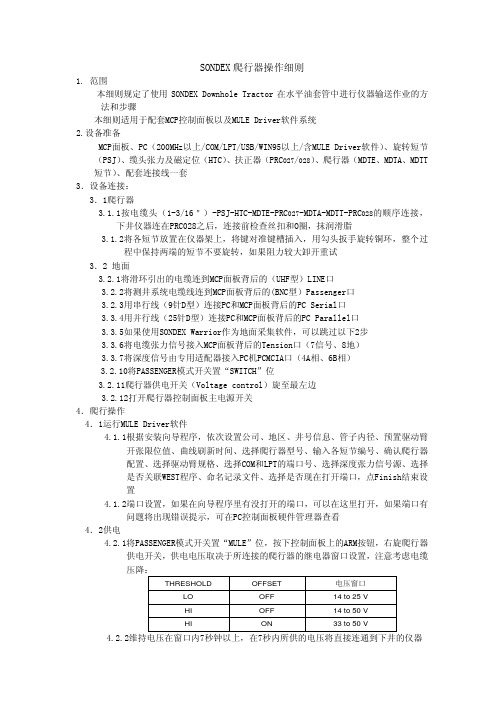
SONDEX爬行器操作细则1. 范围本细则规定了使用SONDEX Downhole Tractor在水平油套管中进行仪器输送作业的方法和步骤本细则适用于配套MCP控制面板以及MULE Driver软件系统2.设备准备MCP面板、PC(200MHz以上/COM/LPT/USB/WIN95以上/含MULE Driver软件)、旋转短节(PSJ)、缆头张力及磁定位(HTC)、扶正器(PRC027/028)、爬行器(MDTE、MDTA、MDTT 短节)、配套连接线一套3.设备连接:3.1爬行器3.1.1按电缆头(1-3/16")-PSJ-HTC-MDTE-PRC027-MDTA-MDTT-PRC028的顺序连接,下井仪器连在PRC028之后,连接前检查丝扣和O圈,抹润滑脂3.1.2将各短节放置在仪器架上,将键对准键槽插入,用勾头扳手旋转铜环,整个过程中保持两端的短节不要旋转,如果阻力较大卸开重试3.2 地面3.2.1将滑环引出的电缆连到MCP面板背后的(UHF型)LINE口3.2.2将测井系统电缆线连到MCP面板背后的(BNC型)Passenger口3.2.3用串行线(9针D型)连接PC和MCP面板背后的PC Serial口3.3.4用并行线(25针D型)连接PC和MCP面板背后的PC Parallel口3.3.5如果使用SONDEX Warrior作为地面采集软件,可以跳过以下2步3.3.6将电缆张力信号接入MCP面板背后的Tension口(7信号、8地)3.3.7将深度信号由专用适配器接入PC机PCMCIA口(4A相、6B相)3.2.10将PASSENGER模式开关置“SWITCH”位3.2.11爬行器供电开关(Voltage control)旋至最左边3.2.12打开爬行器控制面板主电源开关4.爬行操作4.1运行MULE Driver软件4.1.1根据安装向导程序,依次设置公司、地区、井号信息、管子内径、预置驱动臂开张限位值、曲线刷新时间、选择爬行器型号、输入各短节编号、确认爬行器配置、选择驱动臂规格、选择COM和LPT的端口号、选择深度张力信号源、选择是否关联WEST程序、命名记录文件、选择是否现在打开端口,点Finish结束设置4.1.2端口设置,如果在向导程序里有没打开的端口,可以在这里打开,如果端口有问题将出现错误提示,可在PC控制面板硬件管理器查看4.2供电4.2.1将PASSENGER模式开关置“MULE”位,按下控制面板上的ARM按钮,右旋爬行器供电开关,供电电压取决于所连接的爬行器的继电器窗口设置,注意考虑电缆压降:THRESHOLD OFFSET电压窗口LO OFF14 to 25 VHI OFF14 to 50 VHI ON33 to 50 V4.2.2维持电压在窗口内7秒钟以上,在7秒内所供的电压将直接连通到下井的仪器上,成功切换到爬行器后,电流会增加,松开ARM按钮,迅速将供电电压提高到150V以上,电流回落。
爬行器操作方法

爬行器操作方法㈠.爬行器挂离合/断离合、开臂/收臂、下行/上行爬行操作步骤:1.首先把地面系统的电源线插入AC220v,把爬行器控制面板上的串口连接至笔记本串口,再插入加密狗,点击爬行器控制软件,然后打开直流电源和爬行器控制面板电源开关,在爬行器控制软件中的display菜单下选择sensors和outputs菜单,弹出两个窗口如下图所示:2.点击控制软件中的MODE CONTROL下的tractor时,爬行器控制面板上的mule和passenger灯中的mule灯会亮,在此状态下才能给井下仪器供上电。
如下图所示:3.此时直流电源供46v左右电压,此时直流电源的电流表显示为0ma,大约等3秒后电流会变成100ma左右(如果给爬行器挂接的仪器供电可以直接供电至60v以上,不要在45v处停留),此时再把电压升到100v左右等一会电流会变成50ma左右(如果此时直接把电压升到200v左右,继电器和调制解调板上的MOS管Q1会在短时间上承受10W的功率,导致其损毁),然后再升到200---250v之间,此时电流变为25ma左右,然后点击控制软件中的clutch control下的Auto按键(如下图所示:),仪器此时便开始自动挂离合,此时电流为65ma左右,同时观察sensor 中的POS值,逐渐减小,output中的Arm值也会变小,当pos值小到一定程度,电流会增加至350ma左右,此时正在吸离合,大约6秒后,电流降至120ma左右,再降至80ma左右,接着再降至50ma,然后再变至80ma左右,最后停在50ma上,此时离合已经挂上。
4.挂上离合后,在toolselect中选择仪器编号,选中后就把刻度调入了,再点击finger control中的open按键弹出open fingger limit菜单,在open fingger limit菜单下的open position中输入要张开的尺寸,输入完成后点击ok,爬行器开始开腿,此时电流为100ma左右。
自由行走器产品说明书

Freedom WalkerItem 80500Assembly Instructions:Step 1Remove partially assembled walker from shipping container/box.Step 2Caster Assembly and Outriggers:1.Install one caster into each of the female fittings on the bottom frame section.2.Secure each caster by inserting one ½" screw into the pre-drill pilot hole on thefemale fitting and tighten with a Phillips screwdriver.3.Insert the outrigger into each side of the walker next to the casters. The front sectionof the outrigger (three way fitting) must connect into the front section (four wayfitting on the frame). Secure the outrigger with one ½" stainless steel screw. Insert thevertical support legs into the outrigger (4 each of leg piping). Secure each verticalsupport leg with one ½" stainless steel screw.Step 3Adjustable Seat:1.Align bottom of the seat section fittings with the top of the 1" PVC pipe that extendsout from the lower base near the casters. Slide the 1" PVC pipe vertically into the seatsection until the last vertical adjustable hole is exposed. The four safety wire lock pinsfit into each fitting that accommodates the 1" PVC pipe. The (T) fittings and the four(FOUR WA Y) fitting takes 1 safety wire lock pin to secure the 1" PVC pipe from moving.2.Connect the seat section with the bottom half of the 1" PVC pipe. The 1" PVC pipeneeds to be secure with the fittings located above the casters.3.Secure the 1" PVC pipe and with 1 each of the 1" stainless steel screws.80500-INS-LABRevA06 Contents:(1)Partially assembled walker frame, outriggers,adjustable seat and gate(1)PVC back section with mesh vinyl backrest sling(4)Four caster wheels (2 braking / 2 non-braking)(2)Two each parallel arms(4)Four safety wire lock pins, pins are to secure theadjustable height section(1)Adjustable safety belt(14)Fourteen (14) each ½" stainless steel screws(2 each for the back section, 4 each for thecaster section, 8 each for the out-riggers)(6)Six each 1" stainless steel screws (4 each for theadjustable arm section, 2 each for the swing gate)Step 4Parallel Arms:1.Facing the walker, insert the right side arm into the front section (T) fitting and backsection (FOUR WA Y) fitting. Insert the left side arm into the front section with the red strap into the (T) fitting, back section insert into the (FOUR WA Y) fitting.2.Secure both arms with 1 each of the 1" stainless steel screws.Step 5PVC Back Section:Add the PVC back to the rear section of the arms. Secure the PVC back into the female fitting with 1 each of the 1" stainless steel screws.Step 6Swing Gate and Red Safety Strap:Includes one parallel pole (longest) and two vertical poles. The parallel pole serves as the main swing gate. The other two serve as a pivot points for the swing gate.1.Slide the parallel pole into the taller pivot pole. Facing the walker, insert the pivotpole into the (T) fitting on the right side. Secure the vertical pole with 1 each of the 1"stainless steel screw.2.Facing the walker, insert the shorter pivot pole into the (T) fitting into the left side.Secure with 1 each of the 1" stainless steel screw.The red safety strap serves as additional security for the swing gate. The red safety strap must be secured to the gate when the walker is in use.Step 7Safety Bolt:The pre-assembled walker has the strap attached to the (seat) base of the walker. Unroll the strap to finish assembly and loop the strap on the swing gate. Secure the swing gate with the red safety strap by snapping it to the swing gate prior to use of the walker. Red safety strap must be on the right side of the walker.NOTE:MAKE SURE ALL SCREWS AND ADJUSTABLE PARTS ARE SECURED PROPERLY PRIOR TO USING THE WALKER.。
5类爬行卡使用说明

5类爬行卡使用说明英文回答:5 Types of Crawling Cards User Manual.Introduction:Crawling cards are a popular tool used for various purposes, such as climbing walls, exploring caves, or navigating rough terrains. In this user manual, we will provide detailed instructions on how to use the five different types of crawling cards effectively.1. Basic Crawling Card:The basic crawling card is the most common type and is suitable for general crawling activities. To use it, simply place the card on the ground and apply pressure on the top surface with your hand or foot. The card will move forward, allowing you to crawl effortlessly. It is important tomaintain balance and coordination while using the basic crawling card.2. Climbing Crawling Card:The climbing crawling card is designed specifically for vertical surfaces, such as walls or trees. To use it, attach the card to your hands or feet using the provided straps. Apply pressure on the surface you wish to climb, and the card's special gripping mechanism will allow you to ascend easily. Make sure to practice proper climbing techniques and use safety equipment when using the climbing crawling card.3. Cave Exploring Crawling Card:The cave exploring crawling card is equipped with advanced features to navigate narrow and dark spaces. This card has built-in LED lights and a small camera that allows you to see and record your surroundings. To use it, wear the card on your chest using the adjustable harness. Use the control panel on the card to activate the lights andcamera, and crawl through caves with ease. Remember to be cautious and avoid dangerous areas while exploring caves.4. Rough Terrain Crawling Card:The rough terrain crawling card is designed to traverse uneven surfaces, such as rocky terrains or sandy beaches.It has durable rubberized wheels and a sturdy frame that can withstand rough conditions. To use it, place the card on the ground and hold onto the handlebars. Use your body weight to steer and control the card as it crawls over obstacles. Always wear protective gear and be aware of your surroundings while using the rough terrain crawling card.5. Underwater Crawling Card:The underwater crawling card is specially designed for underwater exploration. It is waterproof and equipped with propellers that allow it to move smoothly underwater. To use it, wear the card on your back using the adjustable straps and activate the propellers. Use the control panel on the card to navigate underwater and explore marineenvironments. Ensure you have proper diving equipment and follow safety guidelines while using the underwatercrawling card.Conclusion:In this user manual, we have provided instructions on how to use five different types of crawling cards effectively. Whether you need to climb walls, explore caves, navigate rough terrains, or explore underwater environments, there is a crawling card suitable for your needs. Always prioritize safety and follow the manufacturer's guidelines when using crawling cards.中文回答:5类爬行卡使用说明。
- 1、下载文档前请自行甄别文档内容的完整性,平台不提供额外的编辑、内容补充、找答案等附加服务。
- 2、"仅部分预览"的文档,不可在线预览部分如存在完整性等问题,可反馈申请退款(可完整预览的文档不适用该条件!)。
- 3、如文档侵犯您的权益,请联系客服反馈,我们会尽快为您处理(人工客服工作时间:9:00-18:30)。
Pipeline Crawler System Operating InstructionsModel: DTPXQ-IIIDandong Flaw-Detection Instrument Factory, ChinaTable of Content1.Introduction42.Main Technical Specifications43.System Components44.Operating Principle55.Installation and Operation65.1.Installation 65.2.Operating the Crawler 66.Maintenance and Precautions7er Instructions of the Magnetic Positioning System87.1.Overview 87.2.Working Principle 87.3.System Components 87.4.Settings and Interface of the Emitter Control Panel 97.5.Receiver Sensitivity Adjustment Instructions 107.6.Main Technical Specifications of the Magnetic Positioning System 117.7.Operating Procedures 117.8.Battery Maintenance and Precautions 147.9.Item List 158.Battery Charger User Instructions158.1.Main Features 158.2.Main Technical Specifications 15er Instructions 169.TH-JBQ-3A Field Radiation Alarm User Instructions179.1.Introduction 179.2.Main Features and Applications 179.3.Main Technical Specifications 17er Instructions 179.5.Cautions 189.6.Supplies: 189.7.Warranty for the alarm 1810.Accessories181.INTRODUCTIONThe DPTXQ-III X-ray Pipeline Crawler System is designed for non-destructive test of circumferential butt welds in pipelines such as gas and oil transmission lines. Thanks to its internal circumferential X-ray tube, it can test single circumferential butt welds with just one exposure. Therefore compares to the common outboard testing in the past, the work efficiency increased dramatically, as well as lowered workload of operations.The main features of the system including compact design, low weight, ease of operation, reliable and wide range of applications.2.MAIN TECHNICAL SPECIFICATIONS•Pipeline diameter range: 600-820mm•Thickness of the pipeline: 5-28mm•Max angle of climb: 38°•Travel speed: 15m/min•Travel distance: 0-1000m (Return)•Weight: 200Kg•Power source: DC batteries (120V)3.SYSTEM COMPONENTSThe Pipeline Crawler System consists of the crawler, magnetic positioning system, X-ray generator, DC battery and recharger, radiation alarm.•Crawler: To move the system inside the pipeline.•Magnetic positioning system: Including emitter and receiver, to direct the crawler moving to the precise welding points.•X-ray generator: Generates X-ray which penetrate through the testing area, to acquire an X-ray image.•DC power: A 120V DC battery, to power the whole system.•Recharger: To recharge the battery.•Radiation alarm: Prompting when the crawler is in exposure mode for safety.Figure 1 - Component Illustration 14.OPERATING PRINCIPLEThe crawler can travel inside the pipeline, when remote instructions are received, they will be processed by the CPU to determine whether to move forwards, backwards or stop, and when to start and stop the exposure process. A varies of tasks can be carried out by sending remote instructions to the system.Figure 2 - Component Illustration IIFigure 3 - Component Illustration III5.INSTALLATION AND OPERATION5.1.Installation•Check the package box to see if it’s intact, without cracks and damage.•After unpacking, check the contents according to the package contents list.•Take out the crawler, and then test whether the screws are loosened.•Select the necessary frames and fasten the screws.•Take out the battery cartridge then put it in the crawler.•Connect the X-ray generator to the device, and make sure it’s fastened.•Connect the various plugs.•Mount the Magnetic Positioning Receiver.•Double check the system to make sure the installation is performed correctly before use.5.2.Operating the Crawler(i)Start:Slide the locked switch to the “Power On” position, the crawler will then start moving forward after 3 seconds.(ii)Moving:The crawler will pause 3 seconds after being switched on or exposure is been performed, after that short period, it will start the motor and moving forward until it receives the positioning signal. While it’s on the move, the alarm will beep in every 10 seconds (Moving Beep), each beep lasts for 1 second.(iii)Positioning:Put the positioning emitter on the desired testing area outside the pipeline, when the crawler reaches that point and its onboard positioning receiver pick up the signal, the crawler will stop moving and proceed to the next phase. There are two kinds of positioning:Positioning while moving FORWARD: When the crawler ismoving forward, it will stop immediately when the positioning signalis being received. If the positioning emitter is off in 0~10 seconds,then the crawler will proceed to delayed waiting phase (Alarm willsound at the same time to indicate waiting state), after 20 seconds theX-ray generator will be powered up by high voltage and the crawlerwill proceed to exposure phase. If the positioning emitter is off at11~20 seconds, the crawler will proceed to backward moving state,and start moving backward (Alarm will sound at the same time toindicate backward moving state).Positioning while moving BACKWARD: When the crawler ismoving backward, alarm will beep once every 10 seconds to indicatethe backward moving state, each beep lasts for 1 second; it will stopimmediately when the positioning signal is being received, and thealarm will generate 1Hz (0.5s on, 0.5s off) sound until thepositioning emitter is off, then the motor will start and the crawler willbe moving forward.(iv)Exposure:When the crawler is in exposure phase, the alarm will make 0.5Hz continuous sound until the end of exposure, after that there’s 2 seconds delay and then the motor will start and the crawler will start moving.(v)Errors:There are three kinds of possible errorsLong exposure error:Normally the exposure time should be lessthan 5 minutes, if the exposure time reaches a certain threshold(Exposure time exceed 8 minutes), and there’s still no instructionfrom the emitter to finish exposure, then X-ray generator will beautomatically forced turned off for safety reason; alarm will go off atthe same time and lasts for 2 second, after that crawler will be forcedto move backward.No positioning signal error:If the crawler continues moving formore than 6 minutes without receiving any positioning signal, it willbe considered that the emitter is faulty, the crawler will then soundthe alarm and automatically returns, this is a procedure to prevent theerror of the magnetic positioning system.Water, obstacles blocking, and low battery error:If the crawlerencounters water or other obstacles when it’s on the move, or thevoltage of the battery is lower than a preset value, the crawler will beforced to go back. This is a security measure to protect the safety ofthe crawler.6.MAINTENANCE AND PRECAUTIONS!1. The outer appearance of the crawler and fastening device need to be visuallychecked and make sure they are in working order after each use; When lifting the machine, make sure to apply forces evenly on each side, and do not twist or pull otherwise it may damage the machine.2. Check the battery regularly; do not discharge the battery completely (refer tothe battery requirements section).3. X-ray generator has poor shock absorption; therefore it should be handledcarefully.4. Although the system is very reliable and it comes with alarm, but all fieldpersonnel should still carry a radiation-warning device to prevent accident. Incase the system failed to carry out exposure procedure, the system should bepulled out immediately and checked thoroughly.5. If the crawler failed to work, then it should be pulled out with emergency towdevice.6. Check the battery level and make sure it’s full before each use.7. It is strictly prohibited to use the crawler in the rain or under severe dampenvironment; If the crawler is splashed with water, the power should be turn offimmediately to prevent short circuit, and make sure to dry it off before use itnext time.ER INSTRUCTIONS OF THE MAGNETIC POSITIONING SYSTEM7.1.OverviewThe main features of the systemincludes powerful penetratingability, high positioning accuracy,no harmful radiation, compactdesign and simple operation, it’s amuch better replacement to the oldgeneration of radioactive isotopecesium 137 locator.7.2.Working PrincipleIt adopts the international leadingtechnology of Eddy Current.7.3.System ComponentsThe system consists of two parts including emitter and receiver.The emitter is a battery-powered portable device; the receiver needs stable and independent DC power that provided by the crawler. The emitter is placed on the outside of the pipeline, and the receiver should be mounted on the top of the crawler inside the pipeline.Figure 4 - Positioning Emitter Figure 5 - Positioning Receiver7.4.Settings and Interface of the Emitter Control Panel1. “Penetrating Properties”buttons area: it has three levels, including Thin, Medium and Thick, from weak to strong penetration, select these according to the thickness of the testing material to meet different field testing requirement. Choose “Thin” for small pipeline with thickness of 10mm; choose “Medium” for t h i c k n e s s l e s s t h a n 20mm; choose “Thick” for thickness more than 20mm.2. “+15V +5V -15V” Indicator LED: Indicating the working condition of the emitter’s internal circuit, all three should be o n u n d e r n o r m a l operating conditions.3. “Strength Adjustment” button area: to adjust thepower of the transmission.Greater value indicates strongermagnetic field emission. Theoretical values on the display ranges from 0 to 255, however the real figures are generally smaller, for example “thin” level is usually less than 50, “medium” is usually less than 100, and “thick” is usually less than 150. More magnetic emission power means greater power consumption, therefore it’s not recommended to continuously working under the maximum power for that penetrating setting (It’s when the power wouldn’t increase any more after keeping press the up arrow button).4. “Up” and “Down” buttons in the strength adjustment area: Press “Up” arrow to increase the power, press “Down” arrow to decrease the power.5. “Rapid/Fine Tune”button: To adjust the increase/decrease speed of the strength adjustment. The LED indicator lights up when it’s in “Fine Tune” mode. The default mode is “Rapid Tune”, press the button to switch between these two modes.6. “Voltage Alarm”button: LED for this button does not light normally, but when the voltage is too low (around 27V), the LED will light up and the buzzer will sound immediately to remind the user to recharge the battery of the emitter. The battery should last 10~30 minutes depends on different power settings. Press the button to turn off the alarm state, and the LED indicator will go off.Figure 6 - Emitter Control Panel7. “V/I Monitor”button: press to switch monitoring between voltage andcurrent; If the LED lights up then it’s in the “Current Mode”, the figures showing on the display is the power of the transmission, you can only adjust the power strength in this mode. Press it again to switch to Voltage mode, the LED goes off and you cannot change the power strength in this mode.8. “Set/Lock” button: to lock or unlock settings. You need to press this keyfirst to unlock the settings, and then adjust the penetrating level followed by power strength, after that you may press this button again to lock the settings, the display will flash 2~5 seconds to indicate the system is saving the new settings.9. “Power Saving” switch: it’s close to the handle on the upper side, switchthis off the system will then proceed to power saving mode, and all the settings should be saved; switch this on and the system will power up, ready to work without the need of setting the parameters again. You don’t need to use this switch for a short period of operating time.10. “Power” Switch with lock: The system will boot up after switch it on,and then preform self-test which lasts for around 5 seconds, the figures showing on the display becomes stable. After switch off the system, the power will be cut off completely; all settings will be saved without the need of setting the parameters again.11. Charging Sockets7.5.Receiver Sensitivity Adjustment Instructions1. Two small switches at the bottom of the receiver (in some models theseswitches are at the back of the receiver) which can set 4 different level of sensitivity, showing on the figure below.2. From level 1 to level 4, thesensitivity goes from weak to strongaccordingly. In coordination withdifferent penetration level on theemitter (thin, medium and thick), tosuit a wide range of pipeline withvaries thickness.3. If the transmission cannotpenetrate the pipeline with themaximum power setting on theemitter, you may increase thesensitivity of the receiver.Figure 7 - Sensitivity Settings4. It is recommended to use level 2sensitivity for pipe with thickness less than10mm, and diameter less than 300mm; level 3 sensitivity is used morefrequently for thickness less than 20mm; You may use level 4 sensitivity for thickness more than 20mm; for thickness more than 30mm you should always use level 4sensitivity.5. Note: If there’s serious magnetic interference nearby (from high-voltagewires, transformer substation etc.), You may lower one level of sensitivity on the receiver, and increase the penetrating power on the emitter. Any kind of motor operating around the testing site should be kept away to avoid the direct interference.7.6.Main Technical Specifications of the Magnetic Positioning SystemEmitter:•Input Voltage: DC32V±8V•Rated Power: ≤50W•Penetrating Power: ≤30mm•Weight: 4.7kg•Operating Temperature: -40℃ ~ 80℃•Working Time: more than 8 hours•Size: 225 x110 x 195mmReceiver:•Input Voltage: DC12V/24V±3V•Rated Power: ≤4.8W•Crawler Speed: ≤30m/min (Recommend constant speed: ≤20m/min)•Weight: 0.5kg•Operating Temperature: -40℃ ~ 80℃•Receiver Sensitivity: 4 levels adjustable•Distance between the receiver and the top (inside) of the pipe: 5~10cm (If crawler has large deviation of track, then 10~20cm is recommended)•Accuracy of positioning: ±5mm•Size: 100 x 110 x 27mmAluminum Protective Case: 400 x 315 x 350mmBattery Charger: 220AC/DC16.8V/1.0A Standard Charger7.7.Operating Procedures(i)Transmission Level Setting:Power level on the emitter and sensitivity level on the receiver shouldbe set according to the pipe’s diameter and thickness.(ii)Correct wiring for the receiver:Wiring:Color of power cord: Red (+), White (-)Color of signal cord: Orange, GreyTechnical Standard for the receiver:Power Supply: DC 24VOutput Signal Type: Passive switch(iii)Setting up the devices1. Mount the receiver: Mount the receiver to the front part of thecrawler (away from the motor side), the distance between receiver and the top of the pipe wall should be appropriate. Connect the cable between the receiver and the crawler (Correct wiring needed, otherwise it may damage the receiver or fail to receive the signals), and then tighten up the connectors. Put the crawler into the opening of the pipeline, make sure the receiver is about 1m into the pipeline so that it’s possible to observe the receiver’s LED status.2. Switch off the power of the motor on the crawler, or lift up thewheels, to make sure the crawler doesn’t move while adjusting the signal strength.3. Placing and starting the emitter: Put the emitter on the outer wall ofthe pipe, control panel facing the user, and ensure the emitter is basically in the same vertical line to the receiver. Use the key to switch on the emitter, and then turn on the power saving mode (If the power saving switch is being turned on beforehand, then the emitter will not boot up normally). It may take a few seconds for the emitter to do the self-test, reload the settings from last time. Remember you need to turn off power saving mode before switch off the emitter, and use the key to lock the power switch after that. Continuous power up interval should be more than 5 seconds.4. Adjusting the transmission power: If the blue indicator LED on thereceiver doesn’t light up, increase the emitter’s power by press the up arrow button in the “Penetrating Strength” area, when the blue LED lights up and become stable (not flashing), increase the power a few more steps to ensure a good reception (the emitter can only send signal to the receiver when the blue LED is on), then lock the setting by press the “Set/Lock” button. While adjusting the transmission power, the red LED on the receiver lights up first, and then blue LED lights up. You may also adjust the position of the receiver horizontally so that it’s in the same vertical line to the emitter.If the blue LED on the receiver already lit up without any adjustment, there’s two ways to re-ensure that the transmission power is sufficient. One way to do this is that you may lower the power on the emitter, up to a point where the blue LED on the receiver turns off,and then you may re-adjust again by increase the emitter’s power using the method above; Another way to make sure the transmission power is sufficient, is that you may simply just increase the power a couple of more steps, however this may cause the receiver picks up the signal earlier than desired, and making the crawler stops prematurely, thus to make the whole positioning process inaccurate.5. Do a test run on the crawler first in a short pipeline, and determinethe appropriate distance between the welds and where you should place the emitter.(iv)Operating1. Switch on the crawler, put the emitter close to the outer surface ofthe pipeline, then move it away slowly following the pipeline to send out the signal, the crawler should start working.2. When the crawler starts working, place the emitter on the upperwall of the pipeline close to the weld point, make sure it’s in the same vertical line to the receiver (otherwise it may cause positioning inaccurate).3. After the positioning process finish, take the emitter and move it tothe next testing (welds) point. While moving emitter, the head of the emitter (the side with the locked switch) should be kept facing the same way, and user should also observe the power value on the control panel display, it’s normal if the value changes up or down 1 level.(v)Attention while in operating1. The settings for the emitter (including penetrating level andtransmission strength) should be re-adjusted for pipe with different diameter and/or wall.2. The variation of the distance between the emitter and pipelineshould not exceed 2mm, otherwise you may re-adjust the transmission power (especially for the repositioning when the crawler re-enter the pipeline).3. If necessary, use the power saving switch close to the handle whilecarrying it from one weld point to another, remember to turn it back on upon reaching the next point.4. The receiver is only designed to work inside the pipeline, when it’sout in the open and exposed to the magnetic field for too long, it may damage the receiver.5. The sensitivity level on the receiver cannot be changed while thepower is on, to change it you need to turn off the power first, and thenturn it back on after the new sensitivity level is being set.6. The speed of the crawler may change due to power consumption,and this may affect the positioning accuracy. It is recommended to usethe Magnetic Positioning System on a crawler with steady speedability.7. Try not to set the speed of the crawler too fast, and make sure it’smoving in a straight line, otherwise it may affect the positioningaccuracy.8. The inside and outside surface of the pipeline may be painted withsome special anti-corrosion, anti-static and anti-magnetic materials,when this affects the penetrating ability of the emitter, adjust thepenetrating power of the emitter as well as the sensitivity of thereceiver accordingly.9. After positioning, the crawler proceeds to exposure phase, duringthis period, some electrical parts inside the crawler may generate mildinterference to the receiver, however the signal can be shielded bysetting up certain program during exposure phase.7.8.Battery Maintenance and Precautions1. Battery should not be charged continuously for over 24 hours, or it mayaffect the lifespan of the battery.2. When the battery is not being used for more than a month, you needperform a discharge and recharge to protect the battery.3. If the display on the control panel showing 28 or less when pressing the“V/I” button, it’s not in a good state for long time use; when the low-voltage alarm beeps, you should recharge the battery as soon as possible orthe emitter may turn off automatically.4. When the emitter is in Power-Saving mode(The main locked switch is still on), because thepower is not completely turned off, therefore itwill still drain the battery slowly. Remember toturn off the locked power switch and put it inthe storage case after use.5. To charge the battery, plug the two chargingcables into the two sockets separately. Whenthe LED indicator turns from red to blue, itmeans the charging completed.Figure 7 - Charging Sockets7.9.Item List•Magnetic Positioning Emitter•Magnetic Positioning Receiver•33V/4.8AH High Capacity Rechargeable Battery (pre-installed in the emitter)•Accessories: Battery Charger x2, DC16.8V/1.0A Standard Charger•Accessories: Protective Storage Case•Accessories: Protective Storage Case Key x2, (silver color)•Accessories: Emitter power switch keys x2 (with black handle)8.BATTERY CHARGER USER INSTRUCTIONS8.1.Main FeaturesFigure 9 - Battery Charger•Wide input voltage range•Output voltage value can be adjusted continuously from 120~150V•Output current value can be adjusted continuously from 0.5~5A•To increase the output current, more units can be set in parallel without the need of current process•Input: over-current, over-voltage, under-voltage protection; Output: short circuit, over-current, over-voltage protection; Overheating protection•Intelligent temperature-controlled fan cooling8.2.Main Technical Specifications•Environmental ConditionsOperating Temperature: -20~50℃;Storage Temperature: -40~70℃;Relative Humidity: 90% (40±2℃);Atmospheric Pressure: 70~106 kPa•Dimensions and Weight: 250mm x 210mm x 68mm 3.2Kg•Input Voltage: AC180~264V Frequency: 50Hz±10%•Output Voltage: DC120~150V (factory setting 5A)•Efficiency >90%•Power Factor >0.85•Load Regulation <1%•Voltage Regular <0.1%•Ripple Voltage <1%•ProtectionInput: over-current, over-voltage, under-voltage protection;Output: short circuit, over-current, over-voltage protection;Overheating protection•Thermal Protection Threshold: 80~85℃•Insulation Resistance ≥20MΩ•MTBF ≥50000her Instructions1. Check before connecting the power: observe to see if there’s any damagedue to transportation, such as loosen screws, strange appearance etc.Proper measures should be taken if any problems are being found.2. Connection: connect the safety ground wire and power cord; make surethe connection is correct and firmly tightened.3. Select charging conditions: turn the “Charging Current Selection” knobto 2A; charging time is 10 hours, increase the current appropriately to speed up the charging. Charging voltage should be selected as 135V.4. No-load power up: turn on the power switch, and then output voltageshould be appeared on the voltmeter. Use a small screwdriver to adjust the output voltage setting on the panel to a desired value, turn it clockwise to increase the voltage, counterclockwise to reduce the voltage.5. Connect the output cable: turn off the power, connect the cable to thecharger and rechargeable battery according to the marks on the panel, red wire to the (+) terminal on the charger, green wire to the (-) terminal. Make sure the connection is correct and then connect the 5-pin plug to the battery. Extra caution should be taken as wrongly connection to the terminals may damage the device. All connectors should be connected firmly.6. Adjust charging current: turn on the power, use a small screwdriver toadjust the output current setting on the panel to a desired value (adjustment can only work when there’s input current), turn it clockwise to increase the current, counterclockwise to reduce the current.7. Cooling fan is temperature-controlled, when the internal temperatureexceeds certain point, the cooling fan will be triggered to start, fan speedvaries with different output voltage and current settings, this is normal; When it’s working, do not block the ventilation of the fan.8. When the internal temperature of the device reaches the auto-shutdown threshold, the device will automatically stop working to protect it from being damaged; when the temperature dropped the device will restart and work again.9.Warning: do not charge the battery until you’ve checked the charger is in working order.9.TH-JBQ-3A FIELD RADIATION ALARM USER INSTRUCTIONS9.1.IntroductionThis product is designed according to the special requirement of industrial X-ray testing site, it features a new looking, and wirelessly radiation detection, small size and low weight, high output power, alarm with sound and flashlight, easy to carry.9.2.Main Features and Applications•Alarm with sound and flashlight, 360°sound field •It is widely used in the field of X-ray and γ-ray testing, γ source transportation and indoor monitoring system.9.3.Main Technical Specifications•Sound Pressure: ≥80dB •Sound Frequency: 900Hz •Intermittent Frequency: 1.5Hz •X-ray detection range: 20 meters (open area)•Power Consumption: ≤25W •Size: Φ200mm , Height 225mm •Weight: 3.5kg •Battery Life: 8 Hourser Instructions1. Turn on the alarm by pushing the switch to the “Working” mode, and then place it on a suitable surface.Figure 10 - Radiation Alarm2. Adjust the volume by rotate the control knob to an appropriate level.3. When X-ray is being detected, siren will sound with flashlights.4. Siren will continue to sound for 6 more seconds after X-ray detection isgone, due to the internal data refresh rate.5. Turn the switch back to “Charging” mode when finish.6. The alarm needs to be recharged after working for 8 hours, make sure theswitch is on “Recharge” mode, and then connect the battery charger plug to the alarm, the LED showing green light, the battery should be fully recharged approximately 15 hours.9.5.Cautions1. Only use the supplied charger to charge the battery.2. Handle with care.3. The LED also doubles as a low-power indicator, it will show red lightwhen the battery is really low, and alarm will stop working and should be recharged as soon as possible.9.6.Supplies:Charging Power Adaptor x19.7.Warranty for the alarmManufacturer can repair it for 6 months starting the date of sale.10.ACCESSORIESFor different pipelines with different diameters, there’s varies accessories you can choose for the system, please find it on the separate accessories list.。