谐波潮流计算步骤
电动自行车和三轮车充电器谐波导致农村电压问题的分析

电动自行车和三轮车充电器谐波导致农村电压问题的分析李嘉彬,张涛,杨志杰,杨建华(中国农业大学信息与电气工程学院,北京海淀100083)目前,电动自行车和电动三轮车等电动车在农村地区被广泛用于载人或运输货物,部分农户使用的电动车充电器、电采暖设备质量不能满足要求[1],对农村配电网造成了谐波污染,导致农村配、用电设备损坏[2,3]。
本文研究农村配电网中电动车劣质充电器导致的农户过电压和设备损害问题,在分析电动车充电器谐波产生机理、谐波导致农村配电网电压过高原因的基础上,构建谐波对农村配电网电压影响的仿真模型;对于电动车充电器谐波导致的农村配电网用户电压过高的不同运行状态,采用农村低压配电网实例和现场实测谐波数据进行了仿真验证。
1电动车充电器的谐波产生与现场测量电动自行车和电动三轮车等电动车的蓄电池主要是铅酸电池和锂电池2种。
为减低成本,农村电动车广泛使用铅酸蓄电池。
虽然相关电动车充电技术以及蓄电池材料的研究一直在不断进步,但为兼顾经济性,农村电动车仍存在充电效率不高,充电过程伴随着潜在的安全问题。
1.1电动车充电器的电路结构及谐波目前电动车充电器的型号规格较多,生产厂家不同其性能也不同,有些充电器采用线性变压器降压后整流,有些采用半桥功率变换电路,也有充电器采用单端反激式功率变换线路。
大多数充电器都采用脉冲快速充电法,但为降低成本,不少充电器的电路比较简单,保护功能较差。
在电动车蓄电池的充电过程中,如果电动车充电器充电电流的脉冲幅度和宽度控制不到允许值范围内,极易产生振荡,形成一个谐波源向电网注入谐波。
充电器充电过程产生的谐波会使充电用户的计算机屏幕和电视机显示亮度发生波动,图形或图像发生畸变,甚至会使用户的电气设备内部元件损坏。
此外,谐波会导致线路和设备功率损耗增加;三次谐波及3的倍数次谐波即使在负载三相平衡的情况下也会使不平衡电流大于相电流;充电器导致的谐波还会干扰继电保护设备、电气测量设备、控制和通信电路以及用户电子设备等,会使灵敏设备发生误动作或元件故障。
电力系统谐波成因分析及谐波潮流计算外文翻译
Analysis of power system overtone and overtone tidal current tocalculateFirst, introduction an ideal electrical power system is by the sole constant frequency and the stipulation peak-to-peak value regulated voltage power supply. But in fact, as a result of the recent years along with science's and technology's unceasing development, the high efficiency traded the class equipment and the modulator use, high in the electrical power system presses the nonlinear element which the direct current transmission the application, the massive misalignment load's appearance as well as the power supply system itself existed and so on to cause in the system's voltage waveform distortion to be getting more and more serious, has caused the very big harm to the electrical power system, for example: Causes in the power supply system the part to lose increases, reduces current collector's service life, to disturb the communication system and so on. Serious when even can also cause equipment the damage, automatic control malfunction, relay protection misoperation, thus creates the power cut accident and so on and other questions. So-called " the friend knows other, is undefeated in many battles ", therefore, must realize to the electrical network overtone comprehensive program of public order, must make clear the overtone origin and the electrical network in under the each different movement way the overtone tidal current distributed situation, adopts the corresponding measure limit and the harmonic cancellation, thus changes the friendly power supply system power supply quality and guarantees system's security economy movement.Second, electrical power system overtone's origin in the electrical power system the overtone source is many and varied. Mainly has the following several kinds: in 1, system's each kind of misalignment current collector for example: Trades the class equipment, the modulator, the electrification railroad, the arc furnace, fluorescence the lamp, the domestic electric appliances as well as each kind of electronic energy conservation control device and so on is the electrical power system overtone important source. Even if these equipment supplies its ideal sine wave voltage, it uses the electric current is also non-linear, namely has the harmonic current existence. And these the equipment produces the harmonic current will also pour into the electrical power system, will cause system each place voltage to have the harmonic component. These equipment's harmony the wave content decided that in its characteristic and the working condition, basically has nothing to do with the electrical power system parameter, may regard as overtone constant flow the source. 2, the power supply system itself exists the nonlinear element is overtone another origin. These nonlinear element mainly has the transformer to stir up the capacitor which, thereactor group the magnetism leg, the alternating and direct convertor station's silicon-controlled rectifier controlling element, the silicon-controlled rectifier control and so on.3rd, like the fluorescent lamp, the domestic electric appliances and so on single capacity is not big, but quantity and spreads very greatly in each place, electric power department with difficulty management current collector. If these equipment's current harmonics content is oversized, will then have the serious influence to the electrical power system, to this kind of equipment's current harmonics content, when manufacture namely should limit in certain quantity scope. 4, the generator send out overtone electric potential. The generator will send out the overtone electric potential at the same time also to have the overtone electric potential production, its overtone electricity the potential will be decided by generator's structure and the working condition, basically will have nothing to do with the external connection impedance. Therefore may regard as overtone constant pressure source , but its value is very small.the three, electrical power system overtone tidal current calculates the so-called electrical power system overtone tidal current computation, is through solution network equation In=YnUn (n=3,5,7 ...... n: Agrees wave number the number. In is the overtone source load pours into electrical network's n subharmonic electric current row vector. Yn is electrical network's n subharmonic conductance. Un is in the electrical network a various nodes bus bar n subharmonic voltage row vector). Obtains in the electrical network various nodes (bus bar) the harmonic voltage, enters to obtain in various legs' harmonic current.When in the electrical power system the existence has the overtone source, this time in the system the contact voltage and the branch current will have the higher harmonic. For the determination harmonic voltage and harmonic current's in power supply system distribution, needed to carry on to the overtone impedance constitution equivalent circuit the tidal current computation, when simultaneously in the rectifier unit power supply system possessed forbearance the part existed, but must act according to various legs overtone impedance the nature and the size, whether there is examined the resonant situation. carries on the overtone tidal current computation, must first determine the electrical network part's overtone impedance. (3.1), electrical network each kind of part's overtone impedance: (1), synchronous generator's overtone impedance the qualified generator's electric potential is the pure sine, does not include the higher harmonic, its generator electric potential only exists in the fundamental wave network. in higher harmonic network, because the generator overtone electric potential is very small, this time the visible generator overtone electric potential is zero. Therefore its and so on the value electric circuit is the junctor end and neutral point overtone reactance .And XGn=nXG1-------------(1) in the formula XG1 is when a fundamental wave generator's zero foreword, the positive sequence or the negative sequence reactance, has this subharmonicforeword characteristic to decide , if needs to take into account the network to lose, regarding the generator, may its impedance angle according to 85 degrees estimates, regarding the transmission line, part's and so on transformer and load equivalent generators, may its impedance angle according to 75 degrees estimates. . (2), transformer's overtone impedance the electrical power system overtone's peak-to-peak value often is elevates along with the frequency weakens, therefore in the fundamental wave tidal current computation high tension line , often neglects transformer's initiation leg and the capacitance between turns particularly. When calculates the harmonic current, only considers transformer's leakage reactance, and thought that recognizes the frequency with the harmonic order to be proportional. Generally, as soon as transformer's equivalent circuit simplifies for links to meet the original vice-mid-side node overtone reactance **** *** is the transformer fundamental wave leakage reactance. under higher harmonic's function, the winding internal kelvin effect and approaches the effect to increase, by now transformer's resistance harmonic order's square was proportional approximately with the , this time's transformer overtone impedance is: Zn=sqrt(n)RT1+jnXT1-------------------------------(3) And RT1 is the fundamental wave time-variable depressor's resistance. regarding the three-phase winding transformer, may use the star equivalent circuit, on its overtone impedance computation side Fathom. when the overtone source pours into when higher harmonic current three-phase not symmetry, then must figures out the three-phase overtone impedance according to transformer's wiring way and various forewords impedance meter . 3) reactor's overtone impedance , when only takes into account the reactor induction reactance, to the n subharmonic frequency is: XLn=Nxl*UN/sqrt(3)IN 4), transmission line's overtone impedance the transmission line has the uniform distribution parameter electric circuit, passes through the transmission line which change positionss completely to be possible to regard as is three-phase symmetrical. in tidal current computation, usually by lumped parameter PI equivalent circuit expression. Following chart: in takes into account in the distribution characteristic situation, then: ZLn=Znsh(rnl) Yln/2=(chrnl-1)/(Znshrnl) ZN and RN respectively be regarding in this subharmonic when line's wave impedance and propagation constant. Zn=sqrt(Z0n/Y0n) Rn=sqrt(Z0nYon) Z0N and Y0N respectively be this subharmonic when transmission line unit length impedance and conductance five), load overtone impedance .When overtone tidal current computation, the fundamental wave part may pour into power regarding according to the node, but regards as in the overtone network it is the constant impedance, may think that approximately the synthesis load is an equivalent electric motor. Its synthesis load's overtone equivalent resistance value is: ZN=SQRT (N) R1+JNX1 R1, X1 is the fundamental wave equivalent electric motor's negative sequence resistance, the reactance, its value may by this node fundamental wave voltage, power the value obtain after the conversion. the zero foreword electric current will not enter the load generally,thus in zero foreword's higher harmonic network, may neglect shoulders the leg. when after has determined in the electric circuit various electrical element's overtone impedance, may constitute an overtone function equivalent circuit, with the aim of carrying on the computation, under when plan overtone function equivalent circuit should pay attention to the following several characteristics: (1), the overtone function's equivalent circuit, should take the rectifier unit as a center, according to actual wiring constitution, therefore the rectification installs to set regards as the overtone source, but electrical power system's generator is not appears by the energy, but as overtone source loaded impedance part. (2), the circuit element impedance may use the famous value to carry on the computation, may also use the sign Yao value to carry on the computation. When uses famous value carries on the computation, the complete electric circuit should convert to some voltage reference, is advantageous for the analysis and the application. (3) in the general computation, part's all resistances may neglect, but when system some part occurs either close parallel or strings together the joint resonance, this time's resistance influence actually cannot neglect. (4), in harmonic current approximate calculation, what determined is the rectifier unit side total harmonic current, according to and so on overtone function the effect electric circuit, can determine various legs harmonic current and the voltage distribution. the 3.2nd, overtone tidal current calculates (3.2.1), not to allow the part network overtone tidal current to calculate (1), symmetrical system's overtone tidal current to calculate in the symmetrical system the three-phase situation to be the same, therefore may calculate according to a situation. when has determined the rectifier unit, no matter what after one side total harmonic current, the union overtone equivalent circuit, may determine in the system network, no matter what a leg's harmonic current distribution. Then again pours into the harmonic current according to the node harmonic voltage and the node relational I=YU (in its , Y is overtone conductance), might determine each place node harmonic voltage. Then may extract the tidal current power. It counts to calculate that the step is as follows: , the basis give the operating condition, by usual tidal current computational method solution fundamental wave tidal current. , according to the overtone source working condition, determined other related parameters and need to calculate harmonic order. , calculates various parts overtone parameter, forms various subharmonics node admittance matrix, and calculates the corresponding overtone net to pour into the electric current. , by type IN=YNUN determined that various nodes the harmonic voltage, and calculates various legs harmonic power. in which, should pay attention has the overtone injection current which the overtone instrumental measurement leaves, its phase angle is opposite in the fundamental current phase angle. Therefore after extracting the fundamental current, must carry on the overtone injection current phase angle the revision. Similarly, the system node's power is the fundamental wave power with agrees sum of the wave power, therefore the fundamental wave pours into the power also to carry on the revision. But thelinear load's place fundamental wave pours into the power not to need to revise. (2), the symmetrical system overtone tidal current calculates in the symmetrical system, the three-phase situation is various, moreover mutual influence, must therefore simultaneously carry on three-phase system's idea to calculate. the symmetrical net tidal current's computation may divide into the network various subharmonics network, calculates the fundamental wave network first, after obtaining various nodes fundamental wave the voltage, calculates various overtones tidal current according to it each injection current, then presses this overtone injection current to resolve various subharmonics net to wind the equation, extracts various nodes various subharmonics voltage. (3.2.2), in the rectifier unit power supply system possesses forbearance the part has when the overtone tidal current to calculate , when in the rectifier unit power supply system possesses forbearance the part exists, the capacitor to rectifier unit's phase change process and voltage current wave the shape is influential. Generally under the base frequency, the induction reactance and the capacitance leg's parameter differs really in a big way in the value, does not send produces the resonance effect, but a rectifier unit's non-sinusoidal return route, may regard as is several different frequencies and oscillation amplitude sine electric potential the comprehensive result which affects separately in the return route, because the induction reactance frequency characteristic and the capacitance frequency characteristic are just opposite, have the possibility subharmonic both value to be close in some under the , have the resonance effect. When besides carries on the normal overtone tidal current computation, but also wants to act according to various legs overtone impedance the nature and the size, whether there is examines the resonance.four, summarize in the electrical power system's overtone appearance, regarding the electrical power system movement is one kind " the pollution ". They reduced systemic voltage the unreliable profile quality, not only has affected electrical power system oneself seriously, moreover also harms the user and the periphery communications system. therefore to the electrical power system overtone's research regarding the improvement electrical energy quality, suppresses with the harmonic cancellation has vital significance .中文译文:电力系统谐波成因分析及谐波潮流计算首先一个理想的电力系统是由单一恒定频率与规定幅值的稳定电压供电的。
配电网谐波潮流计算浅析
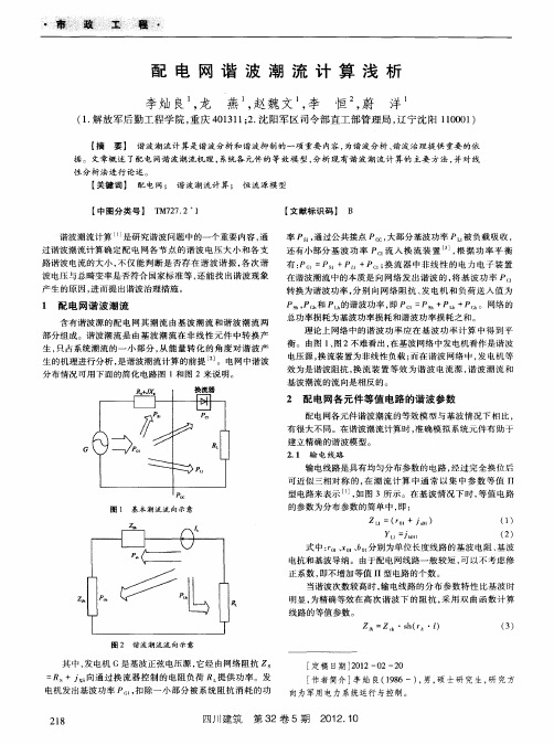
Z =f 4r + i
电抗 。
2 4 谐 波 源模 型 .
(4 1)
式 中 : 、 分 别 为 h次谐 波 时 的 电动 机 等 值 电阻 、 。
由于集肤效应 , 当谐波 次数 越高 时 , 电线 谐波 电阻 也 输
【 文献标识码 】 B
率 P 。通 过 公 共 接 点 P , , 大部 分 基 波 功 率 P 。 负 载 吸 收 , 被 还 有 小 部 分 基 波 功 率 P 。 入 换 流 装 置 , 据 功 率 平 衡 流 根 有 : +P + ; 流 器 中非 线 性 的 电力 电 子 装 置 P。 =P 。 P ,换
正系数 , 即不增加等值 Ⅱ 型电路 的个数 。
当谐波次数较高时 , 电线路 的分 布参 数特性 比基波时 输
墨
明显 , 为精确等效在 高次谐 波下 的阻抗 , 用双 曲函数计 算 采 线路 的等值参数 。
Zf= s( ^・ ) ^ Z h・ h r 1 () 3
图 2 谐 波 潮 流 流 向 示 意
点 电压谐 波分量 对注入电流的影响 , 于是式 (6 简化为 : 1)
, = k U ) k=13 5 …h k g (1 , ,… (7 1)
式中 : 为变压器折算 至高 压侧 的等值 阻抗 ; 变压 z k为
若假定基波 电压 在所研究 时间内基本不变 , 谐波源各 次
注入谐 波电流由式( 7 确定 , 1) , 为恒定值 , 时谐 波源 可看 此
【 中图分类号】 T 7 7 2 M 2 . 1
谐 波 潮 流计 算 t 是研 究 谐 波 问题 中 的一 个 重 要 内容 , 通 过 谐 波 潮 流 计 算 确 定 配 电 网 各 节 点 的 谐 波 电 压 大 小 和 各 支 路 谐 波 电流 的大 小 , 仅 能 判 断 是 否 存 在 谐 波 谐 振 , 次 谐 不 各 波 电压 与 总 畸 变 率 是 否 符 合 国家 标 准 等 , 能 找 出谐 波 现 象 还
谐波潮流计算
谐波潮流计算
谐波潮流计算是一种用于分析电力系统中谐波电流和电压的计算方法。
电力系统中会存在各种非线性设备,如整流器、变流器、电弧炉等,这些设备会引入谐波电流和电压,从而导致电力系统中的谐波问题。
谐波潮流计算的目标是计算电力系统中各节点的谐波电流和电压的大小和相位,以帮助评估系统的谐波问题,并采取相应的措施来减小谐波对系统的影响。
谐波潮流计算通常包括以下步骤:
1. 收集系统数据:包括电力系统拓扑信息、负荷数据、发电机数据、谐波源数据等。
2. 建立系统模型:根据系统数据,建立电力系统的等值模型,包括电阻、电感、电容的等值参数。
3. 谐波源模型:根据谐波源数据,建立谐波源的电流和电压的模型。
4. 潮流计算:根据建立的系统模型和谐波源模型,进行谐波潮流计算,得到各节点的谐波电流和电压的大小和相位。
5. 谐波分析:根据潮流计算结果,对系统的谐波问题进行分析,评估系统的谐波水平,确定可能存在的谐波问题及其影响。
6. 谐波治理:根据谐波分析的结果,采取相应的措施来减小谐波对系统的影响,如加装谐波滤波器、优化电源设备的设计等。
通过进行谐波潮流计算和谐波分析,可以有效评估和解决电力系统中的谐波问题,保证系统的稳定和可靠运行。
谐波计算方法

AB=CD谐波的计算方法关于Gartley形态简述早在1935年有个叫H.M.Gartley的人出了一本书,叫?股市利润?(“Profits in the Stock Market〞),这是一本关于形态技术分析的书,全书厚达700多页,其最为精华的局部在第222页讨论了一个最正确时间与价格的形态,这个形态是非常的强大和有效,后来这个形态被命名为Gartley222,这是以人的名字做为形态的名称。
之后Scott M.Carney在1999年出版了一本叫?和谐的交易?("The Harmonic Trader")的书,这还是一本形态分析和交易的书,Carney在书的第3局部在讨论了Gartley222后介绍和详细讨论了蝴蝶形态〔 Butterfly ),蝴蝶形态分为牛市蝴蝶形态和熊市蝴蝶形态,蝴蝶形态的根底就是Gartley222,丰富了Gartley形态的涵和容。
总结以上系列图片大致分为看涨和看跌二种形态;在我们熟悉的上证指数走势里此类看涨或看跌的蝴蝶形态很多;2712、3361、2890、3181、2319形成看涨的蝴蝶形态,遵循比例关系D=1.618XA;3478、2639、3068、2712、3361形成看跌的蝴蝶;比例关系犹然;〔以上两图是2021年7月截图〕;X、A、B、C、D的核心是AB=CD模式根底上的变化,就AB=CD上涨谐波模式而言,其空间计算方法:A点下跌至B点,开场反弹至C点,C点反弹〔不过A点〕至AB的0.382、0.5、0.618、0.786等,C点形成后自C点作AB的投影〔波浪尺就是投影仪〕,再分别作AB和BC向下的扩展,三组黄金分割聚合区域将是D点的潜在分钟区域。
下跌模式图形反过来用,道理是一样的。
季度线;市场虽然在不断创新低,今天继续创近3年的新低,但是大周期构造的完好说明筑底进展中;市场始终运行于周期嵌套的规律中,周线上我们利用X、A、B、C、D形态模式是在C点形成后可以预测D点的潜在反转区域,从而把握多空转换的机遇。
谐波潮流计算
谐波潮流计算摘要:一、谐波潮流计算的概述二、谐波潮流计算的基本原理三、谐波潮流计算的方法四、谐波潮流计算的应用实例五、谐波潮流计算的优缺点正文:一、谐波潮流计算的概述谐波潮流计算是一种在电力系统中广泛应用的计算方法,主要用来分析和计算电力系统中的谐波电流和电压。
电力系统中的电流和电压通常包含基波和各种谐波成分,而谐波潮流计算就是通过分析这些谐波成分,来计算电力系统中的电流和电压分布情况。
二、谐波潮流计算的基本原理谐波潮流计算的基本原理是基于电力系统的基本电路理论,通过建立电力系统的等效电路模型,然后利用电路分析的方法,计算出电力系统中各节点的电流和电压。
在计算过程中,需要考虑电力系统中的各种元件,如发电机、变压器、线路、负载等,以及它们的电气特性。
三、谐波潮流计算的方法谐波潮流计算的方法主要有两种,一种是基于牛顿- 拉夫逊法(Newton-Raphson)的直接解法,另一种是基于快速迪科法(Fast Decoupled)的间接解法。
直接解法通过迭代计算,直接求解电力系统中的电流和电压;间接解法通过分解电力系统中的电流和电压,然后利用快速迪科法计算出各谐波分量,最后再合成得到电流和电压。
四、谐波潮流计算的应用实例谐波潮流计算在电力系统中有广泛的应用,如在电力系统的运行和规划中,可以用来分析系统的稳定性和可靠性;在电力系统的故障分析中,可以用来计算故障时的电流和电压分布,以便确定故障的位置和性质;在电力系统的谐波控制中,可以用来计算系统的谐波电流和电压,以便设计出有效的谐波控制策略。
五、谐波潮流计算的优缺点谐波潮流计算的优点是计算精度高,可以准确地计算出电力系统中的电流和电压分布;计算速度快,尤其是基于快速迪科法的间接解法,可以大大提高计算效率。
电力网络中的谐波
电力网络中的谐波随着现代工业技术的发展,电网中非线性负荷大量增加,供电电压的波形发生了严重的畸变,影响了电力网和电气设备的安全和经济运行,并危及广大用户的正常用电和生产。
所以对电力网络中的谐波进行研究是很有意义的。
一、电能质量电能质量包括电压质量、频率质量和供电可靠性3个方面.电能质量问题归纳起来主要包括以下4个方面:1电压波动(fluctuation)和闪变(flicker);2谐波(harmonics);3电压三相不平衡(unbalance);4电压降低(dip)和供电中断(outage)。
二、谐波产生的原因非线性负荷从电网中吸收非正弦电流,引起电网电压畸变,电网中的谐波主要是来源于非线性负载,我们可以把谐波源分成以下三种:(1)稳态性谐波源:产生的谐波成分与幅值基本上稳定不变。
如:电网电压稳定时的变压器铁芯非线性特性产生的谐波、带稳定负载的整流器等。
(2)动态性谐波源:产生的谐波具有明显的随机性。
如:电弧炉、电气机车等。
尤其是电弧炉,冶炼过程的不对称性、电弧燃烧的不稳定性,使谐波幅值大小及成分经常变动。
(3)突发性谐波源:这种谐波源在正常运行时并不产生谐波,只是在特定条件下产生。
如:变压器空载合闸的励磁涌流、投入电容器组时的暂态过程即是典型的突发性谐波源。
我们在分析这种谐波源时把它视为一种暂态性谐波。
在电力系统谐波分析中我们又可以把谐波源分成以下两种:(1)电流型谐波源:谐波成分基本上只与其固有的非线性特性及工况有关,而与这些负载外部阻抗的变化几乎无关。
一般非线性负载都可认为是谐波电流源。
如:各种换流设备、电气化铁道、电弧炉及数量很大的电子节能设备、家用电器等典型非线性负载。
(2)电压型谐波源:谐波电势只决定于其本身结构及其工况。
典型的谐波电压源是发电机。
三、谐波的影响和危害谐波的影响和危害是通过改变电抗值(增大感抗、减小容抗)、增加集肤效应和附加转矩等方式产生,还可以通过磁感应、电容耦合方式产生影响。
配电网谐波潮流计算
。
θ Ih1 + Ih2 + 2 Ih1 Ih2 co s h
2
2
( 2)
式中 , Ih1 — — — 谐波源 1 的第 h 次谐波电流 , A;
Ih2 — — — 谐波源 2 的第 h 次谐波电流 , A;
θ — — 谐波源 1 和谐波源 2 的第 h 次谐波电流 h — 之间的相位角 。 当相位角不确定时 ,可按照式 ( 3 )进行计算 。
2 谐波叠加方法
中低压配电系统是一多谐波源共同作用的系统 ,
图 1 不平衡电流注入配网系统
在谐波估算的过程中 , 若已知各谐波源相位 , 则可直
・29・
第 32 卷第 6 期 2009 年 12 月
四川电力技术
Sichuan Electric Power Technology
Vol . 32, No. 6 Dec. , 2009
中图分类号 : T M861 文献标志码 : A 文章编号 : 1003 - 6954 (2009) 06 - 0029 - 04
谐波是电环境的污染物 。像很多其他形式的污 染一样 ,谐波的发生要影响整个电环境 , 而且可能波 及离谐波源很远的地方 。谐波会对电力系统和用户 造成一系列危害 ,比如引起系统局部谐振 , 增加附加 发热和损耗 ,造成设备故障 ; 导致电力设备不正常工 作 ,加速电力设备老化等 。因此 , 对配电网进行谐波 潮流计算 ,估算配电网电能质量情况 , 具有重要的现 实意义 。 中国中低压配电网的三相参数是不对称的 ,而且 由于低压侧单相负荷的存在 , 使得正常运行时 , 三相 负荷通常不对称 。对配电网谐波潮流分析宜采用三 相模型分析法 。如图 1 所示系统 ,假设有若干组谐波 源注入到配电网络 。如果配电网系统为线性无源系 统 ,则可应用叠加原理分别计算各次谐波 。通过直接 求解式 ( 1 ) ,即可求得系统各母线公共连接点的谐波 电压 [ V h ]。
电力系统谐波成因分析及谐波潮流计算-外文翻译
中文译文:电力系统谐波成因分析及谐波潮流计算首先一个理想的电力系统是由单一恒定频率与规定幅值的稳定电压供电的。
但实际上,由于近年来随着科学技术的不断发展,在电力系统中大功率换流设备和调压装置的使用、高压直流输电的应用、大量非线性负荷的出现以及供电系统本身存在的非线性元件等引起系统中的电压波形畸变是越来越严重,对电力系统造成了很大的危害,例如:导致供电系统中的元件损耗增大、降低用电设备的使用寿命、干扰通信系统等.严重时甚至还能使设备损坏,自动控制失灵,继电保护误动作,从而造成停电事故等及其它问题。
所”知己知彼,百战不殆",因此,要实现对电网谐波的综合治理,就必须明确谐波的来源及电网在各种不同运行方式下谐波潮流的分布情况,以采取相应的措施限制和消除谐波,从而改善供电系统供电质量和确保系统的安全经济运行。
其次,电力系统中谐波源是多种多样的。
主要有以下几种:1、系统中的各种非线性用电设备如:换流设备、调压装置、电气化铁道、电弧炉、荧光灯、家用电器以及各种电子节能控制设备等是电力系统谐波的主要来源.即使这些设备提供理想的正弦波电压,它取用的电流也是非线性的,即有谐波电流存在。
并且这些设备产生的谐波电流也将注入电力系统,导致系统各处电压产生谐波分量。
这些设备的谐波含量决定于它本身的特征和工作条件,基本上与电力系统参数无关,可视为谐波恒流源。
2、供电系统本身存在的非线性元件是谐波的又一来源.这些非线性元件主要有变压器激磁支路、交直流换流站的可控硅控制元件、可控硅控制的电容器、电抗器组等.3、用户电器设备产生的谐波分量也会对系统产生影响。
如荧光灯、家用电器等的单容量不大,但数量很大且散布于各处,电力部门又难以管理的用电设备。
如果这些设备的电流谐波含量过大,则会对电力系统造成严重影响,对该类设备的电流谐波含量,在制造时即应限制在一定的数量范围之内。
4、发电机发出的谐波电势。
发电机发出额定电势的同时也会有谐波电势产生,其谐波电势取决于发电机本身的结构和工作条件,基本上与外接阻抗无关。
谐波潮流计算
谐波潮流计算
【原创版】
目录
1.谐波潮流计算的定义和背景
2.谐波潮流计算的基本原理
3.谐波潮流计算的方法
4.谐波潮流计算的应用和意义
5.谐波潮流计算的挑战和发展趋势
正文
谐波潮流计算是一种电力系统分析方法,用于计算电力系统中各节点的电压和电流的谐波分量。
随着电力系统的发展,谐波问题逐渐凸显,谐波潮流计算应运而生,成为解决谐波问题的重要手段。
谐波潮流计算的基本原理是基于电力系统的基本方程和谐波分量的
定义。
电力系统的基本方程包括基尔霍夫电流定律和基尔霍夫电压定律。
谐波分量是指电压和电流的频率是基频的整数倍的分量。
谐波潮流计算就是通过求解这些基本方程,得到电力系统中各节点的电压和电流的谐波分量。
谐波潮流计算的方法主要有以下几种:基于牛顿 - 拉夫逊法、基于快速迪科法、基于扩展欧拉法等。
这些方法各有优缺点,需要根据具体的电力系统特性和计算需求选择合适的方法。
谐波潮流计算在电力系统中具有重要的应用。
首先,它可以用于分析和预测电力系统中的谐波问题,为电力系统的规划和设计提供依据。
其次,它可以用于电力系统的运行和控制,有效地抑制和减少谐波对电力系统的影响。
尽管谐波潮流计算取得了显著的成果,但仍面临着一些挑战和发展趋
势。
首先,随着电力系统的规模和复杂性的增加,计算的难度和计算时间也在增加,需要发展更高效和更精确的计算方法。
其次,电力系统的谐波问题也在不断变化和发展,需要不断改进和完善谐波潮流计算的方法和理论。
总的来说,谐波潮流计算是电力系统分析的重要方法,对于解决电力系统的谐波问题具有重要的意义。
4.4电力系统谐波潮流计算

画出基波潮流和谐波潮流网络,可以写出基波节点 导纳矩阵和谐波节点导纳矩阵。
4.4.2 对称系统的谐波潮流计算
数学模型 (1)基波功率平衡方程
P Psp P 0 Q Qsp Q 0
P、Psp、P
分别为节点基波有功功率偏差量、注入有功功率的给定值及计算值
Q、Qsp、Q 分别为节点基波无功功率偏差量、注入无功功率的给定值及计算值
Z Lh h R1 jhX 1
R Ln
用负荷的额定功率和额定电压为基准,其基波负序电阻 和基波负序电抗可取下列标幺值
R1 jX 1 0.4 j 0.35
jX
Ln
当在负荷点处接有大容量的无功补偿装置时,,应将电 容器作为一个独立支路。
X Cn X C1 n
在零序性的高次谐波网络里,可忽略负荷支路
ch nl 1 Yln 2 Z Cn sh nl
Z Cn Z 0 n / Y0 n
n n _ j n Z 0 nY0 n
Z Cn n
——分别为n次谐波时的特 征阻抗和传播常数,均为 复数。
负荷
除去谐波源后电力系统的其他负荷,主要是工业负荷, 主要成分为由异步电动机群组成的动力负荷
jX
G h
X Gn nX G1
基波计算:按发电机阻抗为纯电抗计算 谐波计算:有功负荷为0或者很小,有功功率只是元件有功损 耗,按电阻形式估计; 发电机按阻抗角为85°估计; 等值发电机(包括线路、变压器及负荷等)按阻抗角为75°估 计
变压器
基波潮流计算:常忽略变压器的励磁支路和绕组电阻 谐波潮流计算: 变压器可看作单独的谐波源,若粗略计算可忽略它的非 线性。 在高频情况下,变压器绕组相间及绕组匝间的电容不可 忽略。 若谐波次数不高时,可以忽略相间和匝间电容,等值电 路如下
谐波的计算方法
AB=CD谐波的计算方法关于Gartley形态简述早在1935年有个叫H.M.Gartley的人出了一本书,叫《股市利润》(“Profits in the Stock Market”),这是一本关于形态技术分析的书,全书厚达700多页,其最为精华的部分在第222页讨论了一个最佳时间与价格的形态,这个形态是非常的强大和有效,后来这个形态被命名为Gartley222,这是以人的名字做为形态的名称。
之后Scott M.Carney在1999年出版了一本叫《和谐的交易》("The Harmonic Trader")的书,这还是一本形态分析和交易的书,Carney在书的第3部分在讨论了Gartley222后介绍和详细讨论了蝴蝶形态(Butterfly ),蝴蝶形态分为牛市蝴蝶形态和熊市蝴蝶形态,蝴蝶形态的基础就是Gartley222,丰富了Gartley形态的内涵和内容。
总结以上系列图片大致分为看涨和看跌二种形态;在我们熟悉的上证指数走势里此类看涨或看跌的蝴蝶形态很多;2712、3361、2890、3181、2319形成看涨的蝴蝶形态,遵循比例关系D=1.618XA;3478、2639、3068、2712、3361形成看跌的蝴蝶;比例关系犹然;(以上两图是2010年7月截图);X、A、B、C、D的核心是AB=CD模式基础上的变化,就AB=CD上涨谐波模式而言,其空间计算方法:A点下跌至B点,开始反弹至C点,C点反弹(不过A点)至AB的0.382、0.5、0.618、0.786等,C点形成后自C点作AB的投影(波浪尺就是投影仪),再分别作AB和BC向下的扩展,三组黄金分割聚合区域将是D点的潜在分钟区域。
下跌模式图形反过来用,道理是一样的。
季度线;市场虽然在不断创新低,今天继续创近3年的新低,但是大周期结构的完好说明筑底进行中;市场始终运行于周期嵌套的规律中,周线上我们利用X、A、B、C、D形态模式是在C点形成后可以预测D点的潜在反转区域,从而把握多空转换的机遇。
谐波潮流计算

谐波潮流计算摘要:一、谐波潮流计算的背景与意义1.电力系统中的谐波问题2.谐波对电力系统的影响3.谐波潮流计算在解决谐波问题中的重要性二、谐波潮流计算的方法1.传统谐波潮流计算方法a.基于矩阵的方法b.基于状态空间的方法2.现代谐波潮流计算方法a.基于神经网络的方法b.基于有限元的方法c.基于粒子群优化算法的方法三、谐波潮流计算的应用1.电力系统谐波分析2.电力设备故障诊断3.电力系统优化与控制四、谐波潮流计算的发展趋势与挑战1.高性能计算技术在谐波潮流计算中的应用2.大规模电力系统的谐波潮流计算3.非线性谐波潮流计算的研究正文:谐波潮流计算在电力系统中具有重要的应用价值,主要目的是解决电力系统中由于谐波问题导致的设备损坏、系统不稳定等问题。
谐波是指频率为基波频率整数倍的电压、电流分量,其产生的原因包括电力设备的非线性特性、电容电流等。
谐波对电力系统的影响主要表现在以下几个方面:1.对电力设备的影响:谐波电流在电力设备中产生附加损耗,导致设备温度升高,影响设备的寿命和安全。
2.对电力系统的影响:谐波会导致系统电压偏差增大,影响电能质量;同时,谐波还会引起系统不稳定,可能引发电力系统事故。
为了解决这些问题,谐波潮流计算应运而生。
谐波潮流计算是对电力系统中谐波电流、电压的分布和传输进行分析和计算的过程,可以帮助我们了解电力系统中谐波的产生、传输和分布规律,从而采取有效的措施抑制谐波。
谐波潮流计算方法有多种,传统方法主要包括基于矩阵的方法和基于状态空间的方法,这些方法在一定程度上可以解决谐波问题,但计算复杂度较高。
近年来,随着计算机技术的快速发展,谐波潮流计算方法也取得了突破性进展,例如基于神经网络的方法、基于有限元的方法和基于粒子群优化算法的方法等。
这些现代方法在提高计算效率的同时,可以更好地解决复杂的谐波问题。
谐波潮流计算在电力系统的应用非常广泛,主要包括电力系统谐波分析、电力设备故障诊断和电力系统优化与控制等。
谐波补偿
什么是谐波补偿你的问题应该分开来问的谐波和补偿是两个不同的概念谐波大多是和功率因数一起来说的而补偿一般是说的无功补偿,也既无功功率补偿下面给你简单介绍一些电力系统谐波成因分析及谐波潮流计算。
一、引言一个理想的电力系统是以单一恒定频率与规定幅值的稳定电压供电的。
但实际上,由于近年来随着科学技术的不断发展,在电力系统中大功率换流设备和调压装置的利用、高压直流输电的应用、大量非线性负荷的出现以及供电系统本身存在的非线性元件等使得系统中的电压波形畸变越来越严重,对电力系统造成了很大的危害,如:使供电系统中的元件损耗增大、降低用电设备的使用寿命、干扰通讯系统等。
严重时甚至还能使设备损坏,自动控制失灵,继电保护误动作,因而造成停电事故等及其它问题。
所谓"知己知彼,百战不殆",因此,要实现对电网谐波的综合治理,就必须搞清楚谐波的来源及电网在各种不同运行方式下谐波潮流的分布情况,以采取相应的措施限制和消除谐波,从而改善供电系统供电质量和确保系统的安全经济运行。
二、电力系统谐波的来源电力系统中谐波源是多种多样的。
主要有以下几种:1、系统中的各种非线性用电设备如:换流设备、调压装置、电气化铁道、电弧炉、荧光灯、家用电器以及各种电子节能控制设备等是电力系统谐波的主要来源。
这些设备即使供给它理想的正弦波电压,它取用的电流也是非线性的,即有谐波电流存在。
并且这些设备产生的谐波电流也会注入电力系统,使系统各处电压产生谐波分量。
这些设备的谐波含量决定于它本身的特性和工作状况,基本上与电力系统参数无关,可视为谐波恒流源。
2、供电系统本身存在的非线性元件是谐波的又一来源。
这些非线性元件主要有变压器激磁支路、交直流换流站的可控硅控制元件、可控硅控制的电容器、电抗器组等。
3、如荧光灯、家用电器等的单个容量不大,但数量很大且散布于各处,电力部门又难以管理的用电设备。
如果这些设备的电流谐波含量过大,则会对电力系统造成严重影响,对该类设备的电流谐波含量,在制造时即应限制在一定的数量范围之内。
谐波的推导公式

谐波的推导公式好的,以下是为您生成的关于“谐波的推导公式”的文章:咱们先来说说谐波这玩意儿。
谐波啊,简单讲就是那些让电信号变得不那么“老实”的捣蛋鬼。
要搞清楚谐波的推导公式,咱得先从基础的正弦波说起。
就像咱们平时骑自行车,那车轮转得平稳,速度也均匀,这就好比是标准的正弦波。
可要是这车轮一会儿快一会儿慢,那就乱套啦,这乱套的部分就有点像谐波。
咱在学校学物理的时候,都知道正弦函数是sin(x) = A * sin(ωt + φ) ,这里的 A 是振幅,ω 是角频率,t 是时间,φ 是初相位。
那谐波是怎么来的呢?比如说,有个电路,里面有个非线性的元件,像二极管啥的。
这二极管啊,它就不是个“听话”的主儿。
电流通过它的时候,它就会把原本好好的正弦波给弄变形。
咱就假设这个非线性元件接收到一个标准的正弦电压输入。
原本应该是完美的正弦波,可经过它这么一搅和,出来的信号就不再那么单纯了。
这时候,我们用傅里叶级数展开这个变形的信号,就能发现除了原本的基波(就是那个标准的正弦波),还多出来好多频率是基波整数倍的波,这些就是谐波。
比如说,基波的频率是 f,那二次谐波的频率就是 2f,三次谐波就是 3f,以此类推。
那谐波的推导公式是怎么来的呢?这就得从数学上好好分析啦。
咱先把那个变形的信号表示成一个周期函数 f(t) ,然后用傅里叶级数展开它:f(t) = a₀ + ∑(aₙ * cos(nωt) + bₙ * sin(nωt))这里的 a₀是直流分量,aₙ 和 bₙ 就是谐波的系数。
要算出这些系数,就得通过积分来求解。
具体的计算过程有点复杂,不过咱们可以大概理解一下思路。
比如说,计算 aₙ ,就得对f(t) * cos(nωt) 在一个周期内积分,然后除以周期的长度。
bₙ 的计算也类似,只不过是乘以sin(nωt) 再积分。
这一套计算下来,就能得到谐波的各项系数,从而得出谐波的表达式。
我记得有一次,我在实验室里做一个关于谐波的实验。
电力系统谐波潮流计算算法综述
电力系统谐波潮流计算算法综述李洪波武汉大学电气工程学院,武汉( 430072)【摘要】谐波潮流计算是谐波分析和管理的一项重要基础工作,在电力系统中占有重要的地位。
本文概述了谐波潮流分布的计算原理,根据谐波潮流计算算法的基本要求,结合谐波潮流计算自身的特点,对应用于谐波潮流计算的 算法进行了分析和评述,并提出了算法改进方面应进一步考虑的问题。
【关键词】谐波潮流基波潮流谐波潮流计算;;【中图分类号】TM744 【 文献标识码】A 【文章编号】()1008-8032200403-0001-04引言0 随着电力电子技术的迅速发展,大量具有非线性特性的电力设备(如电力机车、电弧炉、变 频、变流设备等)投入电网运行,使电网中出现大量谐波,造成电力系统谐波污染,对电力系统的安全、稳定、经济运行构成潜在威胁,给周围电气环境也带来了极大影响,同时也阻碍了电力电子技术的发展。
谐波被认为是电网的一大公害,对电力系统谐波问题的研究已逐渐被人们重视。
谐波潮流计算是谐波问题研究中的一个重要分支,是了解电网谐波特性和进行谐波分析的重要 手段,不仅可以描绘出各种工况下全网的谐波潮流分布,计算出各监测点的谐波指标,同时还可以分析产生各种谐波现象的内在原因,进而提出抑制谐波的措施。
国内外许多专家对电力系统谐波潮流的分布问题进行了一系列有价值的研究工作,以求全面了 解谐波电流在电力系统的各个部分是如何分布的,在系统中各个节点产生多少谐波电压。
本文概述了电力系统谐波潮流计算的基本要求和特点,并对应用于谐波潮流计算的算法进行了分析和评述。
谐波潮流分布的计算原理1 在具有谐波源的情况下,交流系统的潮流由基波潮流和谐波潮流两部分组成,谐波潮流归根结 底是由基波潮流在非线性元件中转换产生,且只占系统潮流的一小部分。
设发电机产生的基波功率为P g1,扣除被系统基波阻抗消耗的基波功率P s1之后,大部分转化为被负荷吸收的基波功率P L1;小部分基波功率P c1流经非线性元件转化为谐波功率。
谐波运动公式
谐波运动公式1.水平方向速度:Vx=Vo2.竖直方向速度:Vy=gt3.水平方向位移:x=Vot4.竖直方向位移:y=gt2/25.运动时间t=(2y/g)1/2(通常又则表示为(2h/g)1/2)6.合速度Vt=(Vx2+Vy2)1/2=[Vo2+(gt)2]1/2合速度方向与水平夹角β:tgβ=Vy/Vx=gt/V07.合位移:s=(x2+y2)1/2,加速度方向与水平夹角α:tgα=y/x=gt/2Vo8.水平方向加速度:ax=0;竖直方向加速度:ay=g备注:(1)平抛运动是匀变速曲线运动,加速度为g,通常可看作是水平方向的匀速直线运与竖直方向的自由落体运动的合成;(2)运动时间由行踪高度h(y)同意与水平扔出速度毫无关系;(3)θ与β的关系为tgβ=2tgα;(4)在元显恭甩运动中时间t就是解题关键;(5)搞曲线运动的物体必存有加速度,当速度方向与难以承受合力(加速度)方向无此同一直线上时,物体搞曲线运动。
拓展延伸:高中物理机械振动与机械振动的传播公式1.四极振动F=-kx {F:答复力,k:比例系数,x:加速度,负号则表示F的方向与x始终逆向}2.单摆周期T=2π(l/g)1/2 {l:摆长(m),g:当地重力加速度值,成立条件:摆角θ<100;l>>r}3.受迫振动频率特点:f=f驱动力4.发生共振条件:f驱动力=f固,A=max,共振的防止和应用〔见第一册P175〕5.机械波、横波、纵波〔见到第二册P2〕6.波发生明显衍射(波绕过障碍物或孔继续传播)条件:障碍物或孔的尺寸比波长小,或者相差不大7.波的干预条件:两列波频率相同(差距恒定、振幅相似、振动方向相同)8.波速v=s/t=λf=λ/T{波传播过程中,一个周期向前传播一个波长;波速大小由介质本身所决定}9.声波的波速(在空气中)0℃:332m/s;20℃:344m/s;30℃:349m/s;(声波就是纵波)10.多普勒效应:由于波源与观测者间的相互运动,导致波源发射频率与接收频率不同{相互接近,接收频率增大,反之,减小〔见第二册P21〕}备注:(1)物体的固有频率与振幅、驱动力频率无关,取决于振动系统本身;(2)强化区就是波峰与波峰或波谷与波谷碰面处,弱化区则就是波峰与波谷碰面处;(3)波只是传播了振动,介质本身不随波发生迁移,是传递能量的一种方式;(4)干预与绕射就是波特有的;(5)振动图象与波动图象;(6)其它有关内容:超声波及其应用领域〔见到第二册P22〕/振动中的能量转变〔见到第一册P173〕。
