dialogic板卡安装配置
Dell EqualLogic FS7600 系列设备 安装和设置指南说明书

Dell EqualLogic FS7600 系列设备安装和设置指南管制型号系列 E02T© 版权所有 2011-2013 Dell Inc. 保留所有权利。
Dell™ 和 EqualLogic® 是 Dell Inc. 的商标。
本文使用的所有商标和注册商标均属其各自所有者的财产。
本说明文件中的信息如有更改,恕不另行通知。
未经 Dell 书面许可,严禁以任何形式进行复制。
发布时间:2013 年 10 月部件号:M1T05-ZH-CN A01目录前言v1 开始之前1EqualLogic 简介 FS76001入门步骤3预安装任务3安全建议3硬件保护4使用防静电腕带4环境要求4技术规格4包装箱内物品6未提供的所需硬件6机架要求7交换机要求7所需工具72 硬件机架安装9设备前面板和背面板9将安装滑轨装入机架的安装原则10将设备安装到机架中的步骤10将滑轨连接到机架11将设备固定至机架12连接挡板133 电源连接15将设备连接至电源154 网络电缆连接17网络配置概览17网络接口端口17网络连接要求和建议18连接网络电缆的步骤19连接客户端网络电缆205 NAS 群集配置21配置 NAS 群集的步骤21收集 NAS 群集配置信息21 NAS 群集网络要求和建议操作22客户端网络22 SAN 网络23内部网络23 NAS 配置参考表格23查找控制器并配置 NAS 群集246 NAS 存储分配25分配 NAS 存储区的步骤25收集 NAS 容器信息25创建 NAS 容器26安全与权限26转移共享所有权27访问 CIFS 共享27访问 NFS 导出277 下一步操作29NAS 群集文档29 NAS 群集操作29 NAS 容器操作30词汇表31索引33iiiDell EqualLogic FS7600安装和设置指南目录iv前言Dell™ EqualLogic® FS Series 设备与 PS Series 阵列相结合,提供高性能、高可用性、可扩展的 NAS 解决方案。
dialogic板卡媒体资源配置

机密 ]新太集团-项目文档[ dialogic板卡媒体资源配置产品名称:IPSwitch 2.0产品编号:文档编号:版本号:编制单位:新太科技技术开发中心编制日期:2005年4月13日拟制人审核批准颜新戈邵德伟1. Dialogic板卡板卡配置文件功能描述测试备注dti16_ISDN_NET5 480中继,支持isdn和7号信令,16通道不能用作话路OKDMN160-16E1dti16_E1CC 480或496中继,No. 7,16通道可用作话路OKnet5DMN1200-4E1ts16Ml1_qs_net5 120中继,支持isdn和7号信令,16通道不能用作话路。
120语音不支持CSPOKMl1_qs_r2mf 120中继,1号信令,16通道不能用作话路120语音不支持CSP OKDM/V1200-4E1ml1_qs_ts16 120或124中继,No. 7,16通道可用作话路120语音不支持CSPOKDM/V1200A-4E1 Ml2_qs2_net5 120中继,支持isdn和7号信令,16通道不能用作话路120语音,支持CSPOKMl1b_qs2_net5 120中继,支持isdn和7号信令,16通道不能用作话路120语音,支持FSKTs16 120或124中继,No. 7,16通道可用作话路120语音ml1b_qs2_r2mf 120中继,1号信令,16通道不能用作话路ml2_qs2_r2mf 120中继,1号信令,16通道不能用作话路ml9b_qs2_e1 120路会议OKml2_ds2_net5 60中继,支持isdn和7号信令,16通道不能用作话路60语音,支持CSPOKml2_ds2_r2mf 60中继,1号信令,16通道不能用作话路60语音,支持CSP OKDM/V600A-2E1ml2_ds2_ts16 60或62中继,No. 7,16通道可用作话路60语音支持CSPOKOKml1b_ds2_ts16 60或62中继,No. 7,16通道可用作话路60语音不支持CSP!OKml10_ds2_net5 60中继,支持isdn和7号信令,16通道不能用作话路60语音60会议支持CSPOKml10_ds2_r2mf 60中继,1号信令,16通道不能用作话路60语音60会议支持CSPDM/V2400Aml1_cpseries 240语音 OKml1b_cpseries 240语音,支OK持FSKOKml10_cpseries 120语音+60会议支持CSPml2c_cpseries 120语音,支OK持CSPOKml5_cpseries 120语音+15传真支持CSPml9b_cpseries 120会议 OKml9c_cpseriesml9e_cpseriesOKml9f_cpseries 120会议+15传真DMF300 fax30.pcd 30传真 OKOK DM/IP601-2E1-100BT ipvs_evs_2isdn_net5_311c60路IP、VOX和中继IPT1200HDSI us_hdsi 坐席 OK。
OMRON CLK网卡及FinsGateWay安装方法
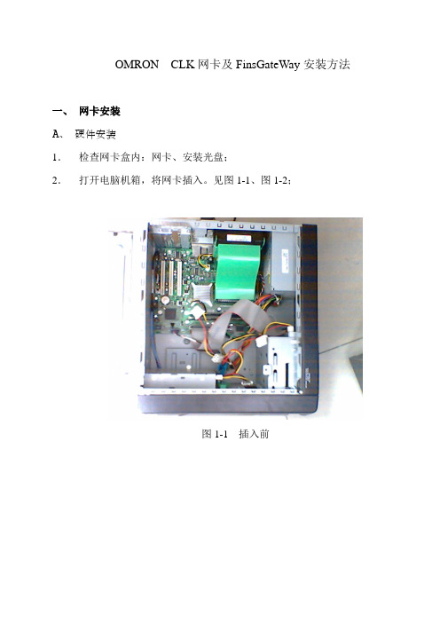
OMRON CLK网卡及FinsGateWay安装方法一、网卡安装A、硬件安装1.检查网卡盒内:网卡、安装光盘;2.打开电脑机箱,将网卡插入。
见图1-1、图1-2;图1-1 插入前图1-2 插入后3. 安装好网卡后,盖上电脑盖板 B 、 网卡驱动程序安装1、打开电脑电源,进入Windows 后,系统发现新硬件,如图1-3图1-3 新的硬件向导12、将CLK板卡的安装光盘放入光驱中,然后按图1-4进行选择;图1-4 新硬件向导23、进入“下一步”后,系统自动安装板卡驱动程序,见图1-5、1-6;图1-5 驱动程序安装1图1-6 驱动程序安装24、出现图1-61-756、进入Windows控制面板—系统—硬件—设备管理器,察看板卡安装的是否正确,如图1-8安装正常图1-8 驱动程序安装正常二、FinsGateWay软件的安装1、打开Windows资源管理器,找到板卡的安装光盘,按照图2-1提示进入FWS2003--CLK(PCI),双击Setup;2、 进入FinsGateWay 安装,如图2-2至图2-7,安装结束后点击Finish ,自动重启电脑。
①②③④图2-2 FinsGateWay软件安装1图2-3 FinsGateWay 软件安装2 Next图2-4 FinGateWay 软件安装 3图2-5 FinsGateWay 软件安装4可任意输入}NextInstall图2-6 FinsGateWay 软件安装 5图2-7 FinsGateWay 软件安装6立即重启电脑Finish4. 重启后在右下角显示FinsGeyWay 图标:5、FinsGetWay 设置: 打开FinsGetWay :点击CLKPCI_UNIT0,单击后进入下个画面3.选中这个选项4选中2CIO1000SendSIZE:100Receive地址:3SIZE:100传送到PLC返回再选中3,按上面的步骤设置并传送CX-Net设置分别双击点3上添加目标分别修改节点2和节点3的链接地址和尺寸链接地址为1000,尺寸为100进入在线传送到PLC中。
gotoneSIU 国通 SS7 网关系统 说明书

gotone SIU™国通SS7网关系统用户手册©2007 版权所有广州国通信息技术有限公司版权声明最终用户软件许可协议许可:广州国通信息技术有限公司,将本软件程序的使用权授予您。
但您必须向本公司作以下保证:不在本协议规定的条款之外,使用、拷贝、修改、租赁或转让本系统或其中的任一部分。
本系统的版权和所有权:本系统及其所有拷贝的名称,与光盘上或本系统中注明的公司同在。
本系统及文档享有版权,并受国家版权法及国际协约条款的保护。
您不可以从本软件中去掉其版权声明;并保证为本系统的拷贝(全部或部分)复制版权声明。
您同意制止以任何形式非法拷贝本系统及文档。
目录版权声明 (2)目录 (3)警告与注意事项 (4)1.概述 (5)1.1.目的 (5)1.2.产品 (5)2.安装 (6)2.1.工作环境 (6)2.2.Telecommunications Compliance (6)2.3.部署拓扑 (7)2.4.前板指示 (8)2.5.后板指示 (8)2.5.1.PCM线路 (8)2.5.2.RJ45接口 (9)3.调试 (9)3.1.参数配置 (9)3.1.1.服务端 (9)3.1.2.客户端 (10)3.1.3.DLL端配置 (11)3.1.4.配置实例 (11)3.1.5.启动 (13)3.2.版权信息 (16)3.3.测试 (16)4.维护 (17)5.升级 (17)警告与注意事项警告WARNING:只有授权的服务工程师方可打开该设备。
在打开该设备之前请认真阅读相关操作手册。
QUALIFIED SERVICE TECHNICIAN OPERA TIONS:Only a qualified service technician is authorized to remove the Top Cover and to access any of the components inside the product. Before removing the Top Cover, read the manual carefully.警告WARNING:不要试图改变AC电源的任何参数。
NMS板卡安装与配置手册

文档编号:NMS板卡安装及配置手册日期:2007-11-29文档修改记录目录索引1 介绍 (6)2 软件安装 (6)3 板卡基本配置 (14)3.1板卡配置——ISDN环境: (14)3.1.1板卡配置第一步 (14)3.1.2配置板卡的第二步 (15)3.1.3板卡配置第三步 (17)3.2板卡配置——SIP环境 (27)3.2.1安装SIP驱动程序 (27)3.2.2申请SIP sip demo license (27)3.2.3启动SIP Server (28)3.2.4板卡中SIP配置 (28)3.2.5压力测试中配置SIP需注意的问题 (33)4 会议配置 (34)4.1.1配置会议第一步 (34)4.1.2配置会议第二步 (38)4.1.3测试会议是否配置成功 (39)5 传真配置 (41)6 启动板卡 (42)7 板卡启不来的解决方法 (44)8 测试板卡 (47)9 跟踪板卡信息 (49)1介绍NMS通信公司是美国的一家从事语音通信领域研究的上市公司。
NMS 通信公司有各种语音板卡,其中AG系列和CG系列板卡是我们最常用的。
AG4000C已经停产,它的升级产品是AG4040C,停产的原因是给NMS公司生产某些芯片的公司部再生产那些芯片了,推出了新的芯片升级产品,所以以后要想用AG卡,一般就只能找到AG4040C了。
我们最常用的CG卡有CG6500C和CG6000。
CG6500C最后的C代表是CPCI插槽,没有C的CG6000指的是PCI插槽,此规律对AG卡同样生效,AG4000C是CPCI插槽的板卡,AG4000是PCI插槽的板卡。
AG系列的板卡的密度低,AG4000最多支持四个E1,AG卡的DSP的资源少,最多不超过40个(我们常用的是8个或16个DSP)。
CG系列的板卡密度高,CG6500最多支持32个E1,最多有96个DSP资源(我们常用的是64个DSP和96个DSP)。
CG6000的密度低,最多有四个E1,我们常用的是16个DSP。
Dialogic Diva产品中文手册

产品手册Dialogic ® Diva ®Dialogic Diva 是一组硬件板卡产品,面向通信应用提供网络连接和呼叫控制,以及丰富的媒体处理功能。
Dialogic Diva 拥有板载 DSP-每个通道独享-支持与数字设备,V.90模拟调制解调器,传真机和 GSM 移动电话通信。
它们的功能和灵活性使其成为远程访问,传真,CTI ,统一消息和 VoIP 网关应用理想的平台,可支持最大 120 路语音,传真,GSM 和模拟通话。
强大的传真解决方案: Diva 板卡(每个通道配置专属的DSP)支持基于T.30传真协议的Group 3传真,包括纠错模式(ECM)和压缩标准(MH; MR; MMR)确保快速和可靠的传真传输可达到33.6kbps(V.34)传输速率。
另外,与第三方应用合作时也可支持Group 4传真,提供64kbps 传真速率。
强大的统一消息解决方案: 强大的Diva 板卡支持创建一个统一消息系统所需的所有功能,包括语音,传真,email 和SMS 。
另外大量标准的补充服务和私有标准扩展为任何应用提供完美的选择。
强大的 CTI 解决方案: 支持标准接口例如TAPI 和CAPI ,Diva SDK 软件开发包支持应用程序轻松的开发,TAPI 服务提供了wave 语言驱动,让Diva 产品成为任何CTI 应用的最佳选择。
Diva 产品线支持所有标准的ISDN 补充服务,包括呼叫转移,呼叫转发,会议以及特定的扩展例如各种音频检查或说话方能量检测等,全面支持任何IVR 或ACD 应用。
高度灵活: 当一个呼叫进入,Diva 会根据呼叫类型自动切换到相应的状态。
不需要将某一通道或某一接口设置为某一种操作专用(例如远程访问);通道可以动态在远程访问,传真和语音模式切换。
所有通道可同时工作,对并发内呼和外呼,传真/调制解调器数量没有任何限制。
Dialogic Diva Soft SS7Dialogic Diva Soft SS7 是一个 SS7 协议栈,提供了MTP (Message Transfer Part) 和 ISUP 功能,通过数字 E1 接口发送和接收呼叫。
PCI7488板卡安装说明

PCI-7488 12位32路高速光隔A/D转换板一﹑概述PCI-7488是带高速光电隔离器件面向工业过程而设计的12位32路A/D转换模板,符合PCI +5V总线标准,适合在所有PC机中运行。
PCI-7488 A/D转换芯片采用高性能的AD1764(BB774),它具有100KHz(10μS)转换速率,自带采样保持、参考电源等功能。
外部模拟量信号经过A/D转换后的数字量与计算机接口之间采用高速光电隔离芯片(光隔通过率1MHz),确保本板A/D转换的高可靠性和对计算机的安全性。
板上带有DC-DC隔离电源模块,用户无需从外部接入电源。
PCI-7488模拟量输入信号由37芯D型孔头接入的,可输入单端32路或双端16路模拟量信号,信号输入范围广,通过改变跳线器就可选择不同的电压范围。
本板占用4个物理I/O端口地址,可采用查询或中断方式工作。
PCI-7488出厂时提供Win95/98/2000/NT下测试程序和动态链接程序(DLL)及编程指导(DEMO程序),有VB/VC 采集程序例程,并提供两年的质保服务。
由于是PCI总线,用户不必关心板卡的实际地址,安装板卡时,PCI协议自动分配该板的基地址PCI-7488采用查询或中断两种方式工作,中断方式由A/D转换完成信号作为中断的触发信号,接到PCI INTA 上。
由于本板路数多,建议用户用查询方式工作。
在实际使用时,A/D转换时间一定,计算机运行速度越快,I/O延时需加大。
本板为四层模板,采用表贴芯片。
技术指标及性能特点:·分辩率:12位·通道数:单端32路/差分16路·A/D芯片:AD1674/BB774·A/D转换时间:10μS·单通道采集速率:100KHZ·输入电压量程:单极性:0~5V;0~10V双极性:±2.5V;±5V;±10V ·物理I/O端口地址:出厂时:BASE+0H~3H·工作方式:软件查询;中断(INTA)·光电隔离器件:一分钟可耐压5000V·电源:DC-DC电源隔离模块,无需外接电源·地线:不共地,数字地与模拟地分离·最大差动输入值:20V(±10V)·输出码制:单极性时为二进原码双极性时为二进制偏移码·总误差:<2‟·可在Win95/98/2000/NT下运行,支持VB、VC·电源功耗:350mA·总线接口:符合PCI总线+5V标准·尺寸大小:165mm×116mm二﹑工作原理1. 原理框图图1:PCI-7488原理框图2.工作原理PCI-7488板由通道多选开关、A/D转换、光电隔离、地址译码、逻辑控制及数据缓冲、PCI-ISA桥等几大部分组成。
Intel Dialogic D 41JCT-LS PCI安装卡快速安装指南说明书
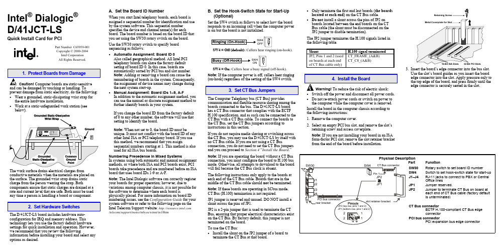
Intel® Dialogic®D/41JCT-LSQuick Install Card for PCIPart Number C65959-001Copyright © 2000-2004Intel CorporationAll Rights Reserved.prevent damage from static electricity, do the following:• Wear a grounded, static-dissipating wrist strap forthe entire hardware installation.• Work at a static-safeguarded work station (seebelow).The work surface drains electrical charges from conductive materials when the materials are placed on the surface. The grounded wrist strap drains static charge from the person wearing the strap. Both components ensure that static charges are drained at a rate and current level that are safe. Both must be used any time a person is handling a board or component.2. Set Hardware SwitchesThe D/41JCT-LS board includes hardware auto-configuration for IRQ and memory address. This technology lets you use the factory default hardware settings for quick installation and operation. However, we recommend that you review the following information before installing your board and select any options as desired.A. Set the Board ID NumberWhen you start Intel telephony boards, each board isassigned a sequential number for identification and useby the system software. This sequential numberspecifies the device and channel name(s) for eachboard. The board number is based on the board ID thatyou set using the SW30 rotary switch on the board.Use the SW30 rotary switch to specify boardsequencing as follows:• Automatic Assignment: Board ID 0Also called geographical method. All Intel PCItelephony boards can share the factory defaultsetting of board ID 0. In this case, boards areautomatically sorted by PCI bus and slot number.Note: Adding or removing a board can cause therenumbering of boards in the system. Consequently,the assignment of device names may change duringthe next system start-up.• Manual Assignment: Board IDs 1–9, A-FIn addition to the automatic assignment method, youcan use the manual or discrete assignment method tofurther identify boards in your system.If you change the board ID from the factory defaultof 0 to any other number, the software will use thatsetting to identify the board.Note: When not set to 0, the board ID must beunique. It must not conflict with the board ID of anyother Intel ISA or PCI telephony board. If you usethis method, we recommend that you assignsequential numbers starting at 1. This method is alsoused for all ISA bus boards.Numbering Precedence in Mixed SystemsIn systems using both automatic and manual assignmentmethods, or where both ISA and PCI boards exist, PCIboards take precedence and are numbered before an ISAboard that uses board IDs 1-9 or A-F.Note: The Intel Dialogic software can correctly registeryour boards for proper operation; however, due tovariations among computer chassis, it is not possible forthe software to determine where each board isphysically placed. For more information on board IDnumbering issues, see the Configuration Guide for yoursystem software or refer to the following page on theIntel Telecom Support website: /telecom/support/tnotes/tnbyos/winnt/tn18htmB. Set the Hook-Switch State for Start-Up(Optional)Set the SW4 switch as follows to select how the boardresponds to an incoming call when the computer poweris on but the board is not initialized.SW4OFFSW4 = Off (default): Callers hear ringing (on-hook).SW4ONSW4 = On: Callers hear a busy signal (off-hook).Note: If the computer power is off, callers hear ringing(on-hook) regardless of the setting of the SW4 switch.3. Set CT Bus JumpersThe Computer Telephony bus (CT Bus) providescommunication and flexible resource sharing among theboards connected to the bus. The D/41JCT-LS boardhas a CT Bus connector that complies with the ECTFH.100 specification, and as such can be connected to theCT Bus with a CT Bus cable. To connect the boards tothe CT Bus, set the CT Bus jumpers according toinstructions in this section.If you do not require media sharing or switching acrossthe CT Bus, you may use the D/41JCT-LS by itself withno CT Bus cable. If you are not using a CT Busconnection, you do not need to set the CT Bus jumpersand you can proceed to Section 4 “Install the Board.”Note: If you are operating the board without a CT Busconnection, you must configure the board to H.100 busmode. Otherwise, all attempts to download to the boardwill fail because the CT Bus clock is absent.The following instructions only apply to the boards ateach end of the CT Bus cable. Boards that are in themiddle of the CT Bus cable should not be terminated.Note: If these boards are operating in SCbus mode,CT Bus (H.100) termination is not required.JP1 jumper is reserved and unused. DO NOT install ashunt across the pins of JP1.JP2 is a 2-pin jumper that is used to terminate the CTBus, ensuring that proper electrical characteristics existon the CT Bus. By factory default, this jumper is notterminated on the board.To use the CT Bus:• Install the shunt on the JP2 jumper of a board toterminate the CT Bus at that board.• Only terminate the first and last boards(the boardslocated at each end) on the CT Bus cable.• Do not install a shunt across the pins of JP2 onboards located between the end boards on the CTBus cable (the shunt must be disconnected on theJP2 jumper to disable termination).The JP2 jumper terminates the H.100 signals listed inthe following table.Shunt H.100 signal terminatedJP2, Pins 1 and 2 (usedon boards at each endof CT Bus cable only)CT_FRAME_(A&B)CT_C8_(A&B)4. Install the BoardWarning!To reduce the risk of electric shock:• Switch off the power and disconnect all power cords.• Do not re-attach power cords or switch on power tothe computer while the computer cover is removed.Install the board in the computer chassis according tothe following instructions:1.Remove the computer cover.2.Select an empty PCI bus slot, and remove the slot’sretaining screw and access coverplate.Note: If you are not installing your board in an ISAform-factor PCI slot, remove the slot retainer bracketfrom the end of the board before installation.Retaining3.Insert the board’s edge connector into the bus slot.Use the slot’s board guides as you insert the boardedge connector into the slot. Apply pressure only tothe top edge of the board, and press firmly until theedge connector is securely seated in the slot.4.Replace and tighten the retaining screw to secure the board. If the screw is not installed and you attach a CT Bus cable to the board, the board may be accidentally unseated from the slot.5.To install an additional board, select an empty PCI slot adjacent to the location of the previous board,and repeat (the second part of) step 2 through step 4.5. Attach CT Bus Cable to BoardThe instructions in this section only apply if you are using CT Bus to connect boards. If you are using the board without a CT Bus connection, skip this section.Use a CT Bus cable to connect your board to other Caution! To preserve the electrical integrity of number of connectors (“drops”). It is recommended that no more than two connectors be left unused at either end of the cable. In addition, it is preferable to distribute the installed boards in slots along the length of the CT Bus cable rather than clustered in one area.Attach the CT Bus cable to the Intel telephony boards as follows:1.Attach the end connector on the CT Bus cable to the CT Bus edge connector on the top edge of the first board in the sequence. The connectors are designed to fit together one way only. If the connector does not seat fully on the board, turn the cable around and try again. Make sure that the colored stripe on the cable faces the rear bracket.2.Attach the cable to the next board until all boards are connected by the cable.3.If the cable has extra connectors or is loose, tuck the cable down so that it does not snag when you replace the computer cover. See the Caution given earlier in this section.6. Connect CT Bus/SCbus Adapter (optional)If you are using only CT Bus boards, or are using the board without a CT Bus connection, skip the instructions in this section.To connect your board to SCbus form-factor boards, use the CT Bus/SCbus adapter. You may use only one CT Bus/SCbus adapter per system .1.Before installing the adapter, the Dialogic boards in your chassis must be positioned in the correct order.The board on which the adapter is installed must be inserted in the first PCI slot adjacent to an ISA slot.Locate this board.2.Align pin 1 of the adapter with pin 1 of the edge connector on the board. Press the adapter onto the board with the SCbus cable connector facing the rearedge of the board.CT Bus / SCbusFor more information, see the hardware installation instructions for the CT Bus/SCbus Adapter.7. Complete Board InstallationAfter you have installed the board(s) and connected the CT Bus cable (and SCbus adapter, if appropriate)replace the computer cover and re-connect power cord.8. Connect External CablesEach RJ-11 jack on the rear bracket of the voice board supports a single voice channel. Use each RJ-11 jack and phone cable to connect each channel to an analog PBX or standard telephone outlet.Since this board emulates a standard telephone, a standard telephone will not function when directlyattached to the board.Note: Connect the Earth Recall signal to pin 2. DONOT connect Tip or Ring lines to pin 2 or improper operation of the D/41JCT-LS will result.9. Install Software, Configure and TestInstall the Intel Dialogic software release and configure the boards as described in the Installation Guide and Configuration Guide for your system software release.Your application software or Intel Dialogic software release may have special installation or configuration requirements. Be sure to read your softwaredocumentation including release note information before you install the software.Note: If you are adding hardware to an existing system,you do not need to uninstall existing Intel Dialogic software.For technical specifications and product information,see the Intel Telecom Products website at/design/network/products/telecom .Direct Return Authorization (DRA)If you are a reseller and are located in the Americas,you may return a board for warranty repair by using the online DRA form at/support/motherboards/draform.htm .For all other returns, contact your vendor or Intel Customer Support (for more information, see /support/9089.htm ).。
30B+d与e1

30B+D业务我们注意到,在CTI应用中,讨论E1技术比较多,而对于ISDN网络讨论较少,这可能和ISDN的应用规模有一定关系。
近年来,ISDN的应用越来越广泛,在CTI中的应用也越来越多,而作为一种端到端的数字传输网络,ISDN也确实有着更多独具特色的优势。
ISDN与30B+D业务ISDN(Integrated Services Digital Network)是以综合数字电话网为基础发展演变而成的通信网,能够提供端到端的数字连接,用来支持话音和非话的各种一线通业务,其中最常见的是2B+D和30B+D。
30B+D业务又称ISDN-PRI,即一次群速率ISDN,能够通过一条PCM提供30个B信道和1个D信道,是提供连接数字PBX、LAN、主计算机和其他设备到网络的经济选择。
图1 30B+D业务30B+D主要应用于:(1)数字程控交换(30个64k的B信道接入)+窄带上网业务(128k带宽);(2)商业机构总部与各分部之间的信息接入直通道;(3)大型企业之间使用专用的会议电视设备,捆绑使用6个B信道(384k)可实现图像实时传送的会议电视业务、捆绑使用2个B信道(128k)可实现图像实时传送的可视电话业务,这里需要提到的是,与E1业务相比,ISDN-PRI优势明显:1.通信业务的综合化。
可以提供电话、传真、可视图文及数据通信等多种业务。
2.实现高可靠性、高质量、高速的通信。
3.使用方便。
信息信道和信号信道分离,接续速度快。
4.费用低廉。
和各自独立的通信网相比,将业务综合在一个网内的费用要低廉得多。
DSS1信令介绍DSS1可能是比较陌生的名词,但是说到Q.931很多人就比较面熟了,在H.323中用于控制呼叫建立和断开的就是使用了Q.931的消息格式。
其实二者是等同的。
DSS1又称为数字一号信令。
DSS1的呼叫控制信息是通过消息的形式传递的,以CTI中常用的电路方式连接控制消息为例,消息分为四大类:第一类是呼叫建立消息,用于启动一个新的呼叫;包括ALERTING(提醒),CALL PROCEEDING(呼叫进程),CONNECT(连接),CONNECT ACK(连接证实),PROGRESS(进展),SETUP(建立),SETUP ACK(建立证实)。
Dialogic IP Media Server快速安装指南说明书

Copyright 2006-2008, Dialogic Corporation Part Number: 939-018-11Copyright © 2006-2008 Dialogic Corporation. All Rights Reserved. You may not reproduce this document in whole or in part without permission in writing from Dialogic Corporation at the address provided below. All contents of thisdocument are furnished for informational use only and are subject to change without notice and do not represent a commitment on the part of Dialogic Corporation or its subsidiaries (“Dialogic”). Reasonable effort is made to ensure the accuracy of the information contained in the document. However, Dialogic does not warrant the accuracy of this information and cannot accept responsibility for errors, inaccuracies or omissions that may be contained in this document. INFORMATION IN THIS DOCUMENT IS PROVIDED IN CONNECTION WITH DIALOGIC® PRODUCTS. NO LICENSE, EXPRESS OR IMPLIED, BY ESTOPPEL OR OTHERWISE, TO ANY INTELLECTUAL PROPERTY RIGHTS IS GRANTED BY THIS DOCUMENT. EXCEPT AS PROVIDED IN A SIGNED AGREEMENT BETWEEN YOU AND DIALOGIC, DIALOGIC ASSUMES NO LIABILITY WHATSOEVER, AND DIALOGIC DISCLAIMS ANY EXPRESS OR IMPLIED WARRANTY, RELATING TO SALE AND/OR USE OFDIALOGIC PRODUCTS INCLUDING LIABILITY OR WARRANTIES RELATING TO FITNESS FOR A PARTICULAR PURPOSE, MERCHANTABILITY, OR INFRINGEMENT OF ANY INTELLECTUAL PROPERTY RIGHT OF A THIRD PARTY. Dialogic products are not intended for use in medical, life saving, life sustaining, critical control or safety systems, or in nuclear facility applications. Due to differing national regulations and approval requirements, certain Dialogic products may be suitable for use only in specific countries, and thus may not function properly in other countries. You are responsible for ensuring that your use of such products occurs only in the countries where such use is suitable. For information on specific products, contact Dialogic Corporation at the address indicated below or on the web at . It is possible that the use or implementation of any one of the concepts, applications, or ideas described in this document, in marketing collateral produced by or on web pages maintained by Dialogic may infringe one or more patents or other intellectual property rights owned by third parties. Dialogic does not provide any intellectual property licenses with the sale of Dialogic products other than a license to use such product in accordance with intellectual property owned or validly licensed by Dialogic and no such licenses are provided except pursuant to a signed agreement with Dialogic. Moredetailed information about such intellectual property is available from Dialogic’s legal department at 9800 Cavendish Blvd., 5th Floor, Montreal, Quebec, Canada H4M 2V9. Dialogic encourages all users of its products to procure all necessary intellectual property licenses required to implement any concepts or applications and does not condone or encourage any intellectual property infringement and disclaims any responsibility related thereto. These intellectual property licenses may differ from country to country and it is the responsibility of those who develop the concepts or applications to be aware of and comply with different national license requirements. Dialogic, Dialogic Pro, Brooktrout, Cantata, SnowShore, Eicon, Eicon Networks, Eiconcard, Diva, SIPcontrol, Diva ISDN, TruFax, Realblocs, Realcomm 100, NetAccess, Instant ISDN, TRXStream, Exnet, Exnet Connect, EXS, ExchangePlus VSE, Switchkit, N20, Powering The Service-ReadyNetwork, Vantage, Making Innovation Thrive, Connecting People to Information, Connecting to Growth and Shiva, among others as well as related logos, are either registered trademarks or trademarks of Dialogic. Dialogic's trademarks may be used publicly only with permission from Dialogic. Such permission may only be granted by Dialogic’s legal department at 9800 Cavendish Blvd., 5th Floor, Montreal, Quebec, Canada H4M 2V9. Any authorized use of Dialogic's trademarks will be subject to full respect of the trademark guidelines published by Dialogic from time to time and any use of Dialogic’s trademarks requires proper acknowledgement. The names of actual companies and products mentioned hereinSelect the Interface Configuration command.Specify an IP address for each interface, including eth0 and eth1.To change the IP address of an interface:• Select the interface to be configured.• Tab to the IP address field.• Enter an IP address.• Enter a network mask.• Make a note of the IP address and apply the change.The next screen displayed is the original screen you saw when you logged in. Tab to the REBOOT option and press ENTER. The IP Media Server reboots and the interface comes up with the specified addresses. All further configuration is done through the Web User Interface. The Web User Interfacearrives configured to use HTTP . If HTTPS is preferred, you can install a security certificate and key on the system using the Web User Interface.6 - continuedUse the keyboard to navigate through the interface.H☞DescriptionNavigate through the fields in the display.Select an option.To apply, cancel or reboot.To access help.Navigation KeyEnter。
7号信令模块使用手册.

7号信令模块使用手册目录7号信令模块使用手册 (1)概述 (3)所支持的硬件 (3)所支持的操作系统 (3)所支持的7号信令协议 (3)所支持的运行模式 (3)和其他模块的关联 (5)7号信令模块和中继模块之间的关联 (5)7号信令模块和7号信令模块之间的关联 (5)7号信令模块和s7m辅助模块之间的关联 (5)模块的配置 (6)配置文件s7au.conf (6)配置文件ss7.conf (6)模块日志解析 (10)日志信息类别 (10)通道标志 (10)中继标志 (10)信令消息 (11)概述7号信令模块(s7au)对业务节点的7号信令消息进行处理,对于7号信令的相关知识另见其他文档。
本文只对7号信令模块的使用作一介绍与说明。
所支持的硬件该模块目前支持下面几种信令卡:1)Dialogic CPM8 cPCI 卡2)Dialogic HDC Blue Branch cPCI卡3)Dialogic HDP Blue Branh PCI 卡4)NMS TX3220C cPCI 卡5)NMS TX4000C cPCI 卡该模块对于 Dialogic 的7号信令卡有一个子模块(s7au_d),对于 NMS 的 7 号信令卡有另外一个子模块进行处理(s7au_n),在实际使用时两个子模块不能互相混用。
如果没有特别说明的,对于两个子模块均适用。
所支持的操作系统目前该模块均能在 Red Hat Enterprise Linux 3 (RHEL3)上面运行。
其中,使用Dialogic 7号信令卡的子模块还能够在 Windows 2000/XP 上面运行。
所支持的7号信令协议支持 ISUP、TUP 协议。
对于其他的应用层信令协议不支持。
其中,基于 Dialogic 的 7号信令卡可以同时支持 ISUP 和 TUP,但是需要专门软件支持,而基于 NMS 的7号信令卡不能同时支持 ISUP 和 TUP,只能选择ISUP或者 TUP。
2024年度ABB工业机器人板卡通讯配置PPT课件

根据系统规模及未来扩展需求,选择具有足 够节点数量和扩展能力的板卡。
2024/3/23
根据通讯速率和距离选型
根据实际需求选择支持合适通讯速率和传输 距离的板卡。
注重诊断和维护功能
选择具有良好诊断和维护功能的板卡,以降 低后期维护成本。
13
04
通讯配置步骤与方法
2024/3/23
提高ABB工业机器人 板卡通讯配置的效率 和准确性
2024/3/23
掌握ABB工业机器人 板卡通讯配置的基本 原理和方法
4
课件内容概述
01
ABB工业机器人板卡通 讯配置的基本概念和原 理
2024/3/23
02
ABB工业机器人板卡通 讯配置的步骤和方法
03
04
ABB工业机器人板卡通 讯配置的实例分析和操 作演示
检查通讯参数
核对通讯速率、数据格式、校验方式 等参数是否匹配。
检查I/O数据配置
检查输入/输出数据的地址、数据类型、 数据长度等配置是否正确。
2024/3/23
22
案例二:ProfiNet通讯配置
2024/3/23
23
案例二:ProfiNet通讯配置
配置网络参数
设置IP地址、子网掩码、网关等网络参数。
核对通讯速率、数据格式、校验方式等参数是否匹配。
检查设备名称、设备类型、设备地址等参数配置是否正确。
2024/3/23
26
案例三:DeviceNet通讯配置
• DeviceNet通讯协议介绍:DeviceNet是 一种基于CAN总线的工业自动化通讯协议, 具有实时性、可靠性、低成本等特点。
2024/3/23
5
语音卡ISDN(PRI 30B+D)信令配置手册
语音卡ISDN(PRI 30B+D)信令配置手册三汇语音卡驱动支持ISDN,即PRI(30B+D)。
ISDN用户一网络接口网络层协议遵循CCITT I.450建议和1.451建议(或Q.930和Q.931建议)。
数据链路层遵循Q.920和Q.921规定。
目前,三汇ISDN信令板卡第16时隙为D通道,在1—15,17—31时隙为语音通道。
1—15,17—31时隙依次和三汇板卡驱动0—29通道号对应。
通道为双向中继。
三汇ISDN信令通过配置可配置成网络侧,用户侧。
请务必咨询交换机方是何种方式,然后遵照交换机为网络侧板卡系统为用户侧或交换机为用户侧板卡系统为网络侧的规则对系统进行配置。
建议按照以下各步进行操作。
三汇ISDN信令板卡同交换机对接工程实施过程中请注意以下事项:1、工控机接地良好。
测试办法:使用万用表的交流电压档,一只表笔接三汇板卡固定片,一只表笔拿在手中,即测试人体同机壳之间的交流电压。
电压不应超过5伏。
解决办法:工控机电源连接线请使用三相插头,务必保证电源接线板第三插孔应接地良好。
若第三脚无接地,那么请使用一导线将计算机机壳与大地(可通过譬如水管,或大楼的地线)相连。
2、从交换机端过来的E1线收发线的屏蔽层是否和BNC金属壳良好连接。
屏蔽层应该和BNC金属壳焊接在一起,或者用专门工具紧密卡接在一起,不能虚绞或根本不连接在一起。
3、从交换机端过来的E1线收发线的屏蔽层是否共地。
测试办法:使用万用表的电阻档,两表笔分别接E1线的金属线屏蔽层(BNC金属壳),若其阻值小于10欧姆,那么可以肯定对端E1的收发线的屏蔽层是共地的。
解决办法:请将板卡上的黑色跳线拔掉,或插在靠近板卡固定片的两个插针上。
4、从交换机端过来的E1线是否正常。
测试办法:将从交换机端过来的E1线同我方板卡断开,并用T型头将其自环,看交换机物理链路是否告警,若有告警,则说明物理连接有故障,需要排除。
此时可请交换机方做传输的相关人员用误码测试仪测试线路上的误码率,十多分钟无误码率。
DSI SS7G3x信令网关

欲了解更多信息,请访问 /cn
Dialogic Corporation 代罗杰克公司北京代表处
9800 Cavendish Blvd., 5th floor 北京市朝阳区建国门外大街甲六号
Montreal, Quebec SK大厦704室
CANADA H4M 2V9 电话: 8610-59632688
Dialogic 是 Dialogic 公司的注册商标。
Dialogic 的商标仅在获得 Dialogic 的许可的前提下方可公开使用。
这种许可仅由在上述地址的 Dialogic 法律部门提供。
本文所提及的实际公司和产品名称分别为其所有者的商标。
Dialogic 鼓励其产品用户获取实施其概念或应用所要求的全部必要知识产权许可证,而这些许可证可能因国家不同而变化。
Dialogic 可能会在不预先通知的情况下在任何时间对产品的规范,描述和计划进行修改。
Linux下Dialogic安装配置手册

Linux下Dialogic驱动安装配置手册© Copyright 2005 - 2008 本手册版权归北京博安天慧科技有限公司所有。
保留所有权利。
未经版权所有者正式授权,禁止将本文档及其派生物以任何形式出版。
本手册所载的商标、服务标志、商号及标识(以下简称“商标”)均为北京博安天慧科技有限公司或他方的注册及未注册商标。
本手册内容及附带代码均“按现状”提供,本公司不对其作任何担保,也不可视为对本公司产品的任何承诺。
目录1. 准备安装环境 (4)1.1. 拷贝安装文件 (4)1.2. 解压缩安装文件 (4)1.3. 解包安装文件 (4)2. 安装驱动 (5)2.1. 运行安装程序 (5)2.2. 显示安装菜单 (5)2.3. 进行安装 (6)2.4. 安装结束 (7)3. 卸载驱动 (8)4. 驱动配置 (9)4.1. 通过config.sh进行配置 (9)4.1.1. 配置DM3板卡 (10)4.1.1.1. 配置界面与物理板卡的对应 (10)4.1.1.2. DMV2400卡的配置 (11)4.1.1.3. DMN160卡的配置 (13)4.1.2. 配置系统时钟 (15)4.1.2.1. 配置时钟编码 (15)4.1.2.2. 配置板卡时钟 (16)4.1.3. 退出config.sh (19)4.2. 启动驱动 (20)4.3. 停止驱动 (21)4.4. 修改配置文件 (21)4.4.1. 语音卡配置文件修改 (22)4.4.2. 中继卡配置文件修改 (22)4.4.2.1. ISDN配置修改 (22)4.4.2.2. CRC配置修改 (22)1.准备安装环境1.1. 拷贝安装文件将linux版本的dialogic安装文件拷贝到准备安装的工控机上,如图1所示图1 dialogic安装文件1.2. 解压缩安装文件使用gunzip命令对安装文件进行解压,如图2所示图2 解压缩后的安装文件1.3. 解包安装文件使用tar xf命令对解压缩后的安装文件进行解包,如图3所示图3 解包后的安装文件2.安装驱动2.1. 运行安装程序运行./install.sh,如图4所示。
IVR系统安装部署说明

文档号:错误!未找到引用源。
版本号:错误!未找到引用源。
日期:错误!未指定书签。
错误!未指定书签。
错误!未指定书签。
错误!未指定书签。
本公司拥有本文档的计算机软件著作权,遵守任何适用的著作权法是用户的责任。
未经本公司的明确书面许可,无论出于何种目的,均不得以任何形式或借助任何手段(电子、机械、影印、录音或其他手段)复制或传播本文中的任何部分,或将其存储于或引入检索系统。
本公司保留删改或变更本文档内容之权力,恕不另行通知。
错误!未指定书签。
修订历史记录版本日期描述修订人初始版本wb目录第一章概述 (1)第一节目标 (1)第二节读者 (1)第三节参考文档 (1)第四节符号说明 (1)第二章安装环境的要求和准备 (2)第一节操作系统和WEB服务器 (2)第二节A V AYA TSAPI的安装和配置 (3)一. AVAYA Tsapi Client 安装 (3)第三章硬件的安装 (4)第一节D IALOGIC板卡的安装配置 (4)第四章系统安装 (7)一. 点击setup.exe开始安装 (7)二. 用户输入提供的产品序列号 (7)三. 选择软件安装目录 (8)四. 选择程序菜单中文件夹名称 (8)五. 安装加密狗驱动 (8)第五章系统配置 (10)一. 点击“开始”->“程序”->“IVR系统”->“硬件配置器” (10)二. 选择“IVR配置” (10)三. 选择板卡类型 (10)四. 选择系统规模 (11)五. 选择板卡型号和资源分配 (11)六. 配置CTI连接 (14)七. 建立IVR分组 (15)八. 建立IVR分机 (16)九. 配置完成后,存盘。
(16)第一章概述第一节目标本文档提供读者一个IVR系统(AVAYA系列版)安装过程的介绍,使读者能够独立地完成系统的安装配置工作。
第二节读者系统集成商或用户的IVR系统安装配置人员,系统维护人员。
第三节参考文档参考文档列表序号文档名称文档号版本号作者第四节符号说明第二章安装环境的要求和准备第一节操作系统和WEB服务器操作系统要求 Windows 2003 Server SP2。
Dialogic 传真板卡 产品手册
产品手册Dialogic® Brooktrout® TR1034 传真板卡Dialogic Brooktrout TR1034 传真板卡是一块高性能,智能的板卡同时支持基于 TDM 和 IP 的传真功能。
Brooktrout TR1034 适用于各种网络的传真应用,可以被集成到文档管理和商业流程自动化系统中,确保符合 Sarbanes-Oxley,HIPAA 和 Basel II 等法律监管需求。
当企业迁移到 VoIP 网络中,灵活的 Brooktrout TR1034可以提供从传统的基于 TDM 的传真系统到混合以及全 IP 的传真系统的轻松迁移路径。
另外,Dialogic 与领先的 IP-PBX 和网关厂商一起合作确保了传真协议的互通性。
支持 PCI 和 PCI Express (PCIe) 总线,Brooktrout TR1034 提供了高速连接速率并被广泛部署在各种线路条件下与绝大多数传真机兼容。
基于 V.34 传真标准以 33.6 kbps 速率发送和接收传真支持 V.8 高速握手和高级压缩提供灵活的配置, 包括 2, 4 和 8 线模拟通道; 8, 10, 16, 20 和 30 线E1/PRI 通道包含 Dialogic DID 内呼传真路由支持 PSTN 和 VoIP 网络支持 T.30 和 T.38 传真协议包含 Dialogic 技术扩展能力 (Technology Expansion Capability, TEC)可以以两倍于14.4 kbps 传真板卡的速率处理传真, 大量节省长途话费缩短三分之一的呼叫建立时间和会话管理时间让方案可轻松扩展支持直接路由传真到特定的用户, 面向传真到 email, 传真文档管理, 工作流和文档传送, 以及法规监管系统可轻松从传统系统移植到 VoIP消除使用 V.90 的造成的 Class 1, Class 2 和其它传真设备造成的安全隐患支持用户通过下载和安装新的授权来增加板卡功能和能力传真处理ITU T.30; ITU T.38; Group 3 V.34, V.17, V.23, V.29, V.27ter, V.21 调制最快 33.6 kbps 可自适应降低普通和高解析度: 100x200, 200x200额外的解析度- 200x400, 300x300, 300x600, 400x800, 400x400, 600x600, 600x1200, 1200x1200 - 100x100, 300x300, 400x400, 600x600, 1200x1200彩色/灰度透传MH, MR, MMR 压缩板载图像转换A4, A3, 和 B4 纸张大小缩放A4 和 B4 TIFF F 文件宽度增强的ASCII 转换包括文档头支持图像透传: 彩色传真T.42 (JPEG), JBIG T.85 (黑白), T.43 (彩色)纠错模式(ECM)线路错误检测/重试语音处理64 kbps G.711 PCM μ-law 和 A-law PCM6 kHz 和 8 kHz 采样率 OKI ADPCM11 kHz 8/16 bit .WAV; 8 kHz 16 bit .WAVDTMF/MF/特殊信息音 (SIT) 检测回放音量控制, 音调纠错速率控制静音压缩呼叫过程和呼叫控制国际呼叫过程和音频检测可编程音频和节拍检测/产生CED, CNG, v.21 调制解调器检测ANI/DNIS, DID, DTMF 和 MF 检测IP-PBX 和 VoIP 网关互通性Dialogic 的 FoIP 产品与业界领先的 IP PBX 和 VoIP 网关互通请参见/interoperability/fax.htm的列表操作系统支持Windows; Linux详细信息访问/systemreleases安装和配置Windows 即插即用兼容图形化配置工具应用编程接口Dialogic Brooktrout Bfv APIBrooktrout TR1034-PCI Express-AnalogTR1034+E2-2L 2 模拟通道; V.34 PCI ExpressTR1034+E2-2L HALF 2 模拟通道; V.34 PCI Express 半长卡TR1034+E4-4L 4 模拟通道; V.34 PCI ExpressTR1034+E8-8L 8 模拟通道; V.34 PCI ExpressBrooktrout TR1034-PCI Express DID and Combo 板卡TR1034+E2C HALF 1 回路启动通道 / 1 DID 通道; PCI Express 半长卡TR1034+E2D HALF 2 DID; PCI Express 半长卡TR1034+E4C HALF 2 回路启动通道 / 2 DID 通道; PCI Express 半长卡TR1034+E4D HALF 4 DID; PCI Express 半长卡Brooktrout TR1034-PCI Express E1TR1034+E4H-E1-1N 4 通道信道化E1; V.34 PCI Express; H.100 或 4 通道; T.38 (V.17): SIP (需要 SDK 5.1.1 或更高) TR1034+E8H-E1-1N 8 通道信道化 E1; V.34 PCI Express; H.100 或 8 通道; T.38 (V.17): SIP (需要 SDK 5.1.1 或更高) TR1034+E10H-E1-1N 10 通道信道化 E1; V.34 PCI Express; H.100 或 10 通道; T.38 (V.17): SIP (需要 SDK 5.1.1 或更高) TR1034+E16H-E1-1N 16 通道信道化 E1; V.34 PCI Express; H.100 或 16 通道; T.38 (V.17): SIP (需要 SDK 5.1.1 或更高) TR1034+E20H-E1-1N 20 通道信道化 E1; V.34 PCI Express; H.100 或 20 通道; T.38 (V.17): SIP (需要 SDK 5.1.1 或更高) TR1034+E30H-E1-1N 30 通道信道化 E1; V.34 PCI Express; H.100 或 30 通道; T.38 (V.17): SIP (需要 SDK 5.1.1 或更高)Brooktrout TR1034 High Density (HD)TR1034+P60H-2E1-1N-R 60 E1通道; V.34 Universal PCI; H.100 或 60 通道; T.38 (V.34); SIP; H.323 - RoHS 兼容TR1034+P90H-3E1-V17-R 90 E1通道; V.17 Universal PCI; H.100 - RoHS 兼容Brooktrout TR1034 Series uPCITR1034-P2-2L HALF 半长; 2模拟通道; V.34 Universal PCI - RoHS 兼容TR1034+uP2C-R HALF 1 回路启动通道 / 1 DID 通道; Universal PCI (需要SDK 5.0.0或更高)TR1034+uP2D-R HALF 2 通道 DID; Universal PCI (需要SDK 5.0.0或更高)TR1034+uP4C-R HALF 2 回路启动通道 / 2 DID 通道; Universal PCI (需要SDK 5.0.0或更高)TR1034+uP4D-R HALF 4 通道 DID; Universal PCI (需要SDK 5.0.0或更高)TR1034+P2-2L-R 2 模拟通道; V.34 Universal PCI - RoHS 兼容TR1034+P4-4L-R 4 模拟通道; V.34 Universal PCI - RoHS 兼容TR1034+P8-8L-R 8 模拟通道; V.34 Universal PCI - RoHS 兼容TR1034+P2-1B-R 2 通道, 单Euro BRI; V.34 Universal PCI - RoHS 兼容TR1034+P4-2B-R 4 通道, 双Euro BRI; V.34 Universal PCI - RoHS 兼容TR1034+P4H-E1-1N-R 4 通道信道化 E1; (V.34) Universal PCI; H.100 或 4 通道; T.38 (V.17): SIP - RoHS 兼容TR1034+P8H-E1-1N-R 8 通道信道化 E1; (V.34) Universal PCI; H.100 或 8 通道; T.38 (V.17): SIP - RoHS 兼容TR1034+P10H-E1-1N-R 10 通道信道化 E1; (V.34) Universal PCI; H.100 或 10 通道; T.38 (V.17): SIP - RoHS 兼容TR1034+P16H-E1-1N-R 16 通道信道化 E1; (V.34) Universal PCI; H.100 或 16 通道; T.38 (V.17): SIP - RoHS 兼容TR1034+P20H-E1-1N-R 20 通道信道化 E1; (V.34) Universal PCI; H.100 或 20 通道; T.38 (V.17): SIP - RoHS 兼容TR1034+P30H-E1-1N-R 30 通道信道化 E1; (V.34) Universal PCI; H.100 或 30 通道; T.38 (V.17): SIP - RoHS 兼容欲了解更多信息,请访问/cnDialogic Corporation 加拿大代罗杰克公司北京代表处9800 Cavendish Blvd., 5th floor 北京市朝阳区建国门外大街甲六号Montreal, Quebec 凯德大厦704室CANADA H4M 2V9 电话: 8610-59632688Dialogic 是Dialogic 公司的注册商标。
E3IPS常见问题处理0429

IPS常见问题处理参考文档:《dialogic串音单通问题的分析方法.doc》Dialogic卡相关问题七号卡问题1.Dialogic信令网关日志查看1)判断信令栈是板卡方式还是主机方式1103 09:08:37 [MANX] run stacks on host从OAMServer读取配置信息,生成Config.txt和System.txt两个文件(在c:\septel下)1103 09:08:37 [MANX] writing config.txt and system.txt3)通过gctload加载配置文件,对7号信令卡进行配置1103 09:08:37 [MANX] try to run gctload1103 09:08:39 [MANX] try to start service Septel1103 09:08:39 [MANX] check service gctserv state1103 09:08:39 [MANX] start service gctserv4)检查配置和信令卡启动结果,如果有不对,会在check boot result…后面显示不对代码1103 09:08:40 [MANX] check boot result...1103 09:08:47 [MANX] board 0: SS7.DC3 V1.51103 09:08:47 [MANX] Hardware Rev 2, RAM 32M, Slot 5 .Firmware Ver1.02Electronic serial number: 01-00000737CB03-82License serial number: 02-0000008C9110-901103 09:08:47 [MANX] activate link 0 ok.1103 09:08:47 [MANX] configuration done1103 09:08:48 [ISP0] stack information: SS#7 ISUP 4.0.等待Link UP,和信令路由成功:Console上会显示Link ? in Service,只有Link UP并且路由通了后,DPC才可用,MG才能注册对应的中继1103 09:13:04 [ISP0] DPC 0x010106 UnAvailable.1103 09:13:05 [ISP0] DPC 0x010106 UnAvailable.1103 09:13:07 [ISP0] DPC 0x010106 UnAvailable.1103 09:13:07 [ISP0] DPC 0x010106 UnAvailable.1103 09:13:41 [ISP0] DPC 0x010106 Available.1103 09:13:41 [ISP0] DPC 0x010106 Available.1103 09:13:41 [ISP0] DPC 0x010106 Available.1103 09:13:41 [ISP0] DPC 0x010106 Available.1103 09:13:41 [SRVX] EVT: DPC 0x010106 resumed..6)等待MG注册消息1103 09:13:42 [SRVX] recv register request for span 12, from 0x00500021.1103 09:13:42 [SRVX] span 12 is free.1103 09:13:42 [SRVX] span 12 is available.1103 09:13:42 [SRVX] the span 12 is registered.1103 09:13:42 [SRVX] totally 2 groups in span 121103 09:13:42 [SRVX] check group info 0 in span 12 ok.1103 09:13:42 [SRVX] check group info 1 in span 12 ok7) 通道复位1103 09:13:42 [ISPX] <12, 1> send RSC.1103 09:13:42 [ISP0] <12, 1> recv RLC (RSC confirmed)8) 启动成功,可看见呼叫信令日志呼叫信令日志格式:DA TETIME [协议+节点号] <SPANID, CHANNEL> send/recv 信令消息内容协议对应TUP或ISP,节点号对应7号信令节点。
- 1、下载文档前请自行甄别文档内容的完整性,平台不提供额外的编辑、内容补充、找答案等附加服务。
- 2、"仅部分预览"的文档,不可在线预览部分如存在完整性等问题,可反馈申请退款(可完整预览的文档不适用该条件!)。
- 3、如文档侵犯您的权益,请联系客服反馈,我们会尽快为您处理(人工客服工作时间:9:00-18:30)。
一.D ialogic CPCI卡
A.DM3卡配置列表
B.DM3卡FCD文件修改说明
坐席卡的修改
打开us_hdsi.fcd文件,查找” ParmEncoding 0=default 1=A-law 2=u-Law”,修改为:
中继卡CRC的修改
以DM/V1200A使用的ml1b_qs2_net5.fcd为例,其他类似。
查找”LineType (dsx1_E1=2, dsx1_E1_CRC=3)”(有几个E1就要修改几处CRC),修改为
中继卡ISDN的修改
查找” ISDN Protocol Mode. 0 = USER_MODE; 1 = NETWORK_MODE” (有几个E1就有几处ISDN类型),默认是用户模式,要改为网络模式,修改如下:
C.SR60一号信令的安装
1、安装DLG的SP1,并且将CFG目录下的文件拷贝到DLG安装目录的相应位置。
2. 将使用1号中继的板卡的配置文件选择为ml2(或ml1)_*(qs2或ds2)_r2mf
打开cfg目录下的pdk.cfg,会有如下内容
board 0 fcdfile ml2_qs2_r2mf.fcd pcdfile ml2_qs2_r2mf.pcd variant pdk_dir_sig.cdp
board 1 fcdfile ml2_qs2_r2mf.fcd pcdfile ml2_qs2_r2mf.pcd variant pdk_dir_sig.cdp
board 2 fcdfile ml2_qs2_r2mf.fcd pcdfile ml2_qs2_r2mf.pcd variant pdk_dir_sig.cdp
board 3 fcdfile ml2_qs2_r2mf.fcd pcdfile ml2_qs2_r2mf.pcd variant pdk_dir_sig.cdp
board 4 fcdfile ml2_qs2_r2mf.fcd pcdfile ml2_qs2_r2mf.pcd variant pdk_dir_sig.cdp
其中pdk_dir_sig.cdp是第1步时copy进去的文件
根据系统的实际配置增加和修改每行的内容
每块板卡一行,Board后面的数字为DCM中看到的该块板卡的编号
例如系统中有两块DMV1200A,DCM中看到编号为0和2,那么pdk.cfg的内容应该为board 0 fcdfile ml2_qs2_r2mf.fcd pcdfile ml2_qs2_r2mf.pcd variant pdk_dir_sig.cdp
board 2 fcdfile ml2_qs2_r2mf.fcd pcdfile ml2_qs2_r2mf.pcd variant pdk_dir_sig.cdp
3、将板卡配置对应的PCD文件,做如下的修改:
查找LocalPool(6) 将2824 改成2872
4. 在DCM启动之前打开命令提示符
运行pdkmanagerregsetup add,会有运行成功的提示
如果系统提示找不到可执行文件,pdkmanagerregsetup.exe在dialogic的bin目录下如果提示运行失败,先运行pdkmanagerregsetup remove后再重复本步骤
6. 启动DCM,
二.D ialogic ISA卡
A.A-LAW配置
将所有板卡的Telephony Bus→PCMEncoding 属性改为 ALAW
B.坐席卡有关配置
如果系统中有坐席卡,中继卡属性MISC→EC_Resource要改为 ON,否则可能出现硬话机按键无法打断拨号音的情况
C.传真卡配置
常见的VFX卡有:VFX/40ESC、VFAX/40ESC Plus
如果你想要使用该卡的传真资源,请将Telephony Bus→D41E_Resource 属性改为ON。
此时这块卡无法做模拟线接入使用。
当D41E设置为OFF时,可作为模拟卡使用。
D.模拟卡配置
常见的LSI卡有:D41/ESC
Telephony Bus→D41E_Resource属性:
ON:作为纯语音资源使用
OFF:作为模拟线接口设备使用
E.ISDN配置
要使用ISDN,先在DCM里配置中继ISDN信令类型如下:
ISDN用户端(CTR4):对应配置文件CTR4.prm
ISDN网络端(NE1):对应配置文件NE1.prm
上述配置文件中可设定ISDN是否使用CRC校验:
;--- Possible values for the data are as follows:
;--- 00H = Turn CRC off.
;--- 01H = Turn CRC on.
;--- The default data value is 00H (Turn CRC off).
000F 01
01 表示使用00 表示不使用
B. 过机卡配置
1) 驱动安装
使用5.01驱动程序,安装时不要选择DM3和GlobalCall。
驱动安装完成后加上genload.exe,getnode.exe和getnode_real.exe三个Patch。
2)配置过机卡前,对于需要设置为主时钟的过机卡,需要修改Dialogic驱动Data目录下的ScxBus.prm文件,将
“;PARM[253]=0020H”修改为“PARM[253]=0010H”
3)按DCM里的向导配置过机卡,先配置第一个节点,然后配置第二个节点
4)配置完成后启动Dialogic驱动,在Master节点和Slave节点使用Dialogic附带的ScxInfoTool 查看过机卡信息,Clock一栏里的ScxBus Right应该为Present,否则请检测过机卡配置是否正确。
如果Master节点的ScxBus Right为not Present,请检查是否执行了第3)步操作。
5)配置后再启动DCM时可能会提示是否配置过机卡,选择否即可。
6)如果在节点里添加或移除了板卡,需要重新配置过机卡。
重新配置过机卡前,需要清空Dialogic\CFG目录,并删除之前生成的scxmap.dat文件。
C. GammaLink配置
1) 驱动安装:安装Dialogic驱动时记得选中GDK,支持GammaLink传真卡
2)安装完驱动,配置GDK
在Dialogic System Software 菜单栏里找到 Configure GDK项,点击这一菜单,将会出现GDK的配置窗口,
在“Main”页面下点击“Control Panel Applet”按钮,如果您是新安装后第一次配置。
配置程序将弹出对话框,如图,告诉您GammaLink的注册键值没有恢复,查找错误的日志文件。
对这三个提示框,您只要点击“确定”就行了。
然后,配置程序将出现如图的版面,注意了,它的属性栏下还没有出现通道的信息。
看到下面的三个可用的按钮了吗?找到“AutoDetect…”, 点击一下,将弹出提示框如图BoardDetect,按“确定”让系统自动查找。
要是系统检测有GammaLink卡,就会弹出如下图的对话框,注意了!请您务必要选中“SC,A-Law”一项!然后按“OK”。
系统就会提示您检测完成,出现Configuration2.bmp 的版面,所有的GammaLink通道将出现在列表框中。
请双击每一通道或选中通道后按旁边的“Properties”按钮,将出现如Channels.bmp的配置框,请确保选中“Auto Answer”和“Use Qeue File”两项,然后按“确定”。
这一通道就配置完了。
当所有的通道都配置完毕,您只要按“确定”,就完成了对GammaLink的配置。
也许您还发现Configuration2.bmp中还有“Restore Registry…”和“Save Registry…”两个按钮。
您配置好之后,可以用“Save Registry…”来保存您的配置,要是以后还想恢复为同样的配置,只要点“Restor Registry…”来恢复就行了。
3)启动GammaLink服务前需要做的事
启动服务顺序:
a.启DCM
b.在命令行下执行如下两条命令:
C:Fax\GfqReset.exe -p3 -q2
C:Fax\gfsh.exe -f C:Fax\gfsh.cmd(执行本条命令时可能会报“不能打开服务驱动”的错误,此时先启、停GammaLink System Service,再重新执行b)
c.启GammaLink System Service
停服务顺序:
a.停GammaLink System Service
b.停DCM。
