RF天线座CONN ipex SMT板端规格书
天线座 产品规格

DOC. No.: 核准/日期
Rev.:A 审核/日期
Page: 2/3 制作/日期
产品料号: 天座
6、SMT温度曲线图
7、外形尺寸
A
A
2 3
Section "A-A"
1
产品规格书
DOC. No.: 核准/日期
Rev.:A 审核/日期
Page: 3/3 制作/日期
产品料号: 天线座
8、印制板(PCB)焊盘
9、包装规格 9.1 上带的剥离力度:300mm/分的速度进行剥离,力度最大应该是0.7N。
1 165°-
80°
9.2 包装方式:载带包装,1000Pcs/卷(Ф178mm)
CONTACT
使用方向 空载带 空载带
组件
10、存储条件 温度:-10 ~ +40 ℃ 湿度:15 ~ 85 % RH 有效期:6 个月
产品规格书
DOC.NO
Rev.:A
Page: 1/3 制作/日期
核准/日期
天线座
≤3GHz 1.3 max 1.3 max
1、简述 本产品适用于RF电路微带同轴传输转接口,应用于移动电话,无线网络,袖珍型PCI,蓝牙,掌上 电脑,全球定位系统,电子测量仪器,等等。 2、技术参数 2.1 额定电压 2.2 频率范围 2.3 特性阻抗 2.4 工作温度 2.5 工作湿度 3、电性能 3.1 绝缘电阻 3.2 耐 压 3.3 接触电阻 3.3.1 内导体 3.3.2 外导体 3.4 电压驻波比(VSWR)
60VAC(R.M.S) 0~6GHz 50Ω -40℃~+90℃ 90% MAX
500MΩ 200V AC 1Min 20 mΩ max 10 mΩ max
胶棒天线规格书
胶棒天线规格书一、引言胶棒天线是一种常用的无线通信天线,它具有结构简单、安装方便等特点,在各种无线通信设备中得到广泛应用。
本规格书将详细介绍胶棒天线的规格参数和性能特点,以便用户了解并正确选择使用。
二、外观和尺寸1. 外观:胶棒天线外形为圆柱形,通常采用黑色或灰色的塑料材质,具有光滑的表面。
2. 尺寸:胶棒天线的长度一般在10至50厘米之间,直径为0.5至1.5厘米,具体尺寸可根据需求进行定制。
三、频率范围胶棒天线的频率范围是指其能够接收和发送信号的频率范围。
一般来说,胶棒天线的频率范围是由其设计和制造时采用的材料和结构决定的。
常见的胶棒天线频率范围为700MHz至2700MHz,适用于各种无线通信标准,如2G、3G、4G和5G等。
四、增益胶棒天线的增益是指其辐射功率相对于理想点源辐射功率的比值,通常以dBi(dBisotropic)为单位表示。
胶棒天线的增益决定了其在特定频率范围内接收和发送信号的效果。
一般来说,胶棒天线的增益越高,其覆盖范围越广,但也容易受到干扰和衰减的影响。
常见的胶棒天线增益范围为2dBi至9dBi。
五、工作温度和湿度胶棒天线的工作温度和湿度是指其能够正常工作的环境条件范围。
一般来说,胶棒天线的工作温度范围为-40℃至+85℃,工作湿度范围为10%至95%。
在超出这些范围的环境条件下使用胶棒天线可能导致性能下降或损坏。
六、阻抗胶棒天线的阻抗是指其与无线通信设备之间的匹配程度。
一般来说,胶棒天线的阻抗为50欧姆,与大多数无线通信设备的阻抗匹配。
如果胶棒天线与设备的阻抗不匹配,将导致信号的反射和损耗,影响通信质量。
七、安装方式胶棒天线的安装方式多种多样,常见的有螺纹固定和磁吸式两种。
螺纹固定方式适用于需要固定在设备上的场景,而磁吸式方式适用于需要频繁安装和拆卸的场景。
用户在选择胶棒天线时应根据实际需求和使用环境选择合适的安装方式。
八、辐射特性胶棒天线的辐射特性是指其在不同方向上发射和接收信号的能力。
无线通信-RF板安装详细说明
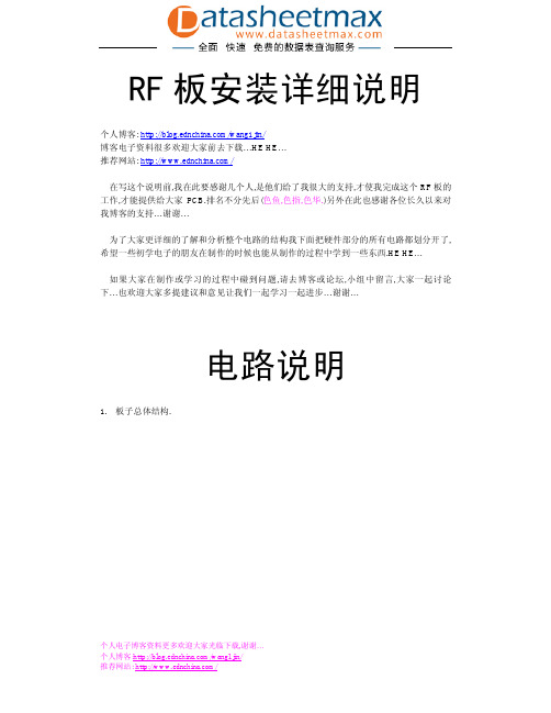
RF板安装详细说明个人博客: /wang1jin/博客电子资料很多欢迎大家前去下载…HE HE…推荐网站: /在写这个说明前,我在此要感谢几个人,是他们给了我很大的支持,才使我完成这个RF板的工作,才能提供给大家PCB.排名不分先后(色鱼,色指,色华.)另外在此也感谢各位长久以来对我博客的支持…谢谢…为了大家更详细的了解和分析整个电路的结构我下面把硬件部分的所有电路都划分开了,希望一些初学电子的朋友在制作的时候也能从制作的过程中学到一些东西.HE HE…如果大家在制作或学习的过程中碰到问题,请去博客或论坛,小组中留言,大家一起讨论下…也欢迎大家多提建议和意见让我们一起学习一起进步…谢谢…电路说明1. 板子总体结构.大家可以看得到…以上为RF板总体结构…整机主要是由STC2052+LCD1602+M62429+BH1415+MIC+键盘红外和高频放大部分组成.主要的工作原理是这样…电路通电后…默认是关机状态.LCD无显示.按下开机键LCD上面显示频率和音量大小.并点亮LCD背光和接通BH1415 及后面一级高频放大电路9018这一级电源.按动按键可以调节频率的加减和音量加减.并会在LCD上实时显示出来…音量控制由M62429来完成,音频信号经过M62429后直接送到BH1415输入端.MIC部分是完成话筒信号放大,并把放大的信号送到BH1415后级和音频混合在一起去调制振荡达到音频和MIC声音混合在一起.可以实现声音和音乐同时发送.MCU部分是由STC2052构成,2052完成检测检测,红外数据解码,音量控制,LCD显示,BH1415控制以及电源控制.BH1415是一个FM立体声芯片, 内部包括音频立体声的产生,锁相环以及输出放大级.BH1415输出的信号直接经过C9018-C3355-C2053三极放大后经滤波和阻抗匹配后输出.原理图各部分详细说明:1.电源部分.MIC部分由电源跳线,音量控制,及后级三极管放大而成.电源部分跳线是为了能适应动圈和驻极体式话筒而设置了.如果用动圈的可以断开跳线就可以…放大的信号经过S8跳线输出到BH1415和立体声音频信号混合调制高频信号.完成混合音频电路.4.MCU部分.本电路采用了一个红外接收头,可以实现遥控来代替手动操作的功能…注(目前程序中没有这功能)…键盘电路是采用四个按键的方式来完成操作…键盘和LCD的IO口是复用的方式. 写程序的时候要注意…7.FM小信号部分.这里是FM产生的小信号处于部分…整个电路由BH1415来完成…(何时能有我们中国的FM 芯片啊…) BH1415包括了FM所有的功能…BH1415留有四个接口接单片机,在些我们用了其中三个,静音的功能没有用….FM输出的信号经C12输出到三极管放大电路…8.三极管放大电路…三极管放大电路主要是把前级放大的信号进行再进一步放大…在这里由三级放大完成,第一级由9018来完成,第二极是C3355,最后一级是C2053…电路中的C9在实际中是没有用到的…请大家注意….放大后的信号经C2053直接送到LC滤波电路…9.LC滤波电路…因为FM放大电路的末级是由D类来完成,因为D类的放大电路效率高,但有个缺点就是波形失真太严重,所以要在后级加上LC滤波电路,LC滤波电路完成滤波把C2053输出的波形滤成正弦波另外就是实现阻抗匹配…安装说明想成功完成一个电子制作,需要耐心加上细心…电子制作就是如此…我会在下面把需要注意的地方弄成红色,请大家一定要注意细心…边看原理图边装.不要把排线弄错了,一定要仔细检查后才能通电试验….否则轻则电路不能工作,重则损坏重要元件….详细的步骤请大家看下面….因为这个是高频的板,所以有些难度所以请大家一定要细心和耐心…另外请准备好一台FM立体声收音机和一个直流12V 1A的电源.…注意:可能元件会有一定的离散性,调试的时候,有条件最好自己准备一些小容量瓷片电容.如几P到几十P范围内…1. PCB图片…由于PCB是晚上照的…所以效果很差.请大家谅解….大家收到PCB图片会如上所示….2. PCB处理…收到PCB后,第一步工作就是把按键板和主板分开…哈哈.千万不要焊好再分…到时候麻烦得很…我是深有体会啊…3. 装相关排线….收到的排线都会是散的…大家要装好…不能装反了.装反了通电很可能会坏…大家在拿到排线的时候要和电路对一下….这个千万要注意….4. 装好面板.面板就几个按键和一个外面接收头和接插件.注意这个插座的安装…可能你的方向和我不一定一样…只要和电路原理图上连接方向要一定对才行…5. LCD拿到手的LCD也是要进行焊的…在LCD底部焊上一排单排排针…到时候可以插上16PNI 的排线用来显示…LCD在插上排线的时候也要注意不要弄反了.否则LCD可能会损坏.6.RS232下载工具…装好了上面这些基础的东西…下面的就是需要一个232下载的工具…在FM板上特别留有一个RS232的下载接口…四根线.分别是: VCC P30 P31 GND…我上面这块板是我以前焊的一个板HE HE…现在派上用场了…6. 主板的焊接.完成上了上面的制作就可以进行焊接主板了,主板部分我们可以把除了三极管放大和LCD滤波部分不装外,别的部分可以全部焊好…焊好了主板后要仔细检查,否则一通电可能会损坏东西.在确定没有短路的情况下,接上12V电源…接通电源后LED应该会亮.如果不亮则去检查下是否有焊接问题…焊好完成的主板如上图看示…焊好完成后,通电把程序写到单片机内部…注(如果不会的话,可以去我博客找找相关的资料和文章.)7.调试MCU部分.写好程序进单片机内部后,拔掉电源,连上LCD和键盘板…再通电LCD上应该有显示….显示的不同和你下载的程序不同…HE HE…按第一个键实现开机.开机后电路会显示频率和音量数据.如上图所示.8.调试FM部分…上述操作都没有问题的话…给FM板接上音源.MP3电脑等音源都可以…调节频率到100M.音量调节到合适位置…打开你的FM收音机…应该能收到FM板发出的信号…如果收音机中收不到…请拉长上图中的电感…一般拉长一点就能收到.如果拉很长了都收不到,可能你元件有焊错或没焊好…请仔细检查…直到能正常的收到为止…9.调试MIC部分.MIC部分有二个跳线…跳线1的作用是是否把MIC接入到电路中.如果不短路这个跳线MIC 声音将无法送到BH1415中进行调制.如果不需要MIC功能的朋友这个跳线最好不要装.跳线2的作用是是否为MIC提供电源.如果是动圈的朋友则不能把这个短路.一般大家都是用驻极体式话筒,一般我们是要短路的.根据话筒的不同,大家也可以改下MIC偏置电路.右边一个蓝色的电位器是MIC音量电位器…这个大家需要根据自己的需要来调节.太大了将会产生啸叫,太小了声音听不到…具体情况大家根据实际情况来调节…HE HE…有了这个功能,大家可以把这个当成一个小功率无线电台来用了!10.FM后级调试FM由这三级放大来完成…千万不要小看了这三级如果调得不好…这个根本无法工作,这就是高频和低频电路的差别…所以调节后面这三级的时候一定要注意和小心…我们在这里是一级级来调…一般的爱好者都没有高档的仪器来进行调试…没有仪器的朋友可以制作上图的检测工具来对高频信号有无进行检测…上面由二个电容二个二极管组成…输出可以接上数字表…根据电压的大小来判断信号的强度,判断放大电路是否有工作…每一级的信号应该会比前一级的要大…如果某一级的信号小于前级这级就有问题了…调试后级的步骤是这样…先焊好第一级C9018这一级的元件…R3,T1,Q1 R5 C19 C6这几个元件…为板子通上电…用上面的检测工具来测量BH11415的输出和经过三极管的输出相比较是否有放大.如果有放大,调节T1使88-108的频率放大量最大.这级就调试完毕.C3355和C2053这二极也是这样的方式来调节…但大家千万要注意的是在调试C2053这一级的时候,要把后级的LC电路也焊上…C2053接上负载电阻…如果不接上负载电阻C2053可能会因此而发热烧毁…负载电阻用50欧2W这参数.最好是用无感电阻.这样能减少C2053的发热…正常工作的C2053温升会比较高.这个是正常的…而且C2053这级输出的信号可以串联一个5P小电容来推动一个小灯炮发光啊…HE HE…高频和低频差别就是相当大.调好了三级放大,接着就是调试最后的LC电路…LC电路大家没有仪器,可以调节电感的长度和可调电容的大小来完成,调节到88—108这带宽都有较大功率输出就可以…调试完成了…有条件的朋友最好给板子加上屏蔽,不然很可能会干扰…在实际的调试过程中C2053输出的信号甚至干扰到了数码相机不能正常工作…如果把天线放在离板太近了.也会导致CPU停止工作…所以最好给RF板弄上一个屏蔽,这样才能较好的让板子工作…板子的天线,最好用专业的天线…自己制作也可以…拉杆天线用在这上面效果不是很理想…大家可以去我博客找找有关天线制作的资料,我博客上有一个…HE HE…最后想和大家说的就是…高频的电路和低频的差别很大,在调试的时候,大家一定要很细心和耐心才行,在安装的时候要注意排线和后级C2053.如果有弄错,可能会导致东西损坏…特别是在后级调试要注意接上负载电阻…在调试完所有的电路后,大家可以给板子加上一个屏蔽,再弄一个外壳装起来…应该会好看很多….在此祝各位朋友调试成功…HE HE…加油…。
射频接头I-PEX规格书
客户确认
盖章 批准
技术审核 技术确认
RoHS审核 RoHS确认
供应商:深圳市飞宇信电子有限公司 联系方式:0755-89737182 地址:深圳市横岗镇西坑宝桐南路76号
深 圳 市 飞 宇 信 电 子 有 限 公 司
SHENZHEN FMC ELECTRONICX CO.,LTD.
规格承认书
Specification for Approval 客户名称: Customer: 规格描述: Part name 飞宇信料号: Part No. 客户料号: Customer Part No. 客户承认印 APPROVAL CUSTOMER APPROVED BY CHIEF SUPERVISOR 新大陆 IPEX 板端 1113-0008
福建新大陆通信科技股份有限公司
样品技术规格书
供应商
供应商名称 深圳市飞宇信电子有限公司 产品名称 物料料号 规格/型号 生产日期 送样日期 2015.02.09 2015.02.09 IPEX板端 产品名称 物料料号 规格/型号 确认日期
客户
客户名称 福建新大陆通信科技股份有限公司
供应商确认
盖章 批准 审核 拟制 王斌 顾长飞 蒋新平
深 圳 市 飞 宇 信 电 子 有 限 公 司
SHENZHEN FMC ELECTRONICX CO.,LTD.
INDEX.
1) 2) 3)
封面........................................................................................... 1 目录............................................................................................ 2 图面............................................................................................ 3
CommScope 6-接口扇形天线产品说明书
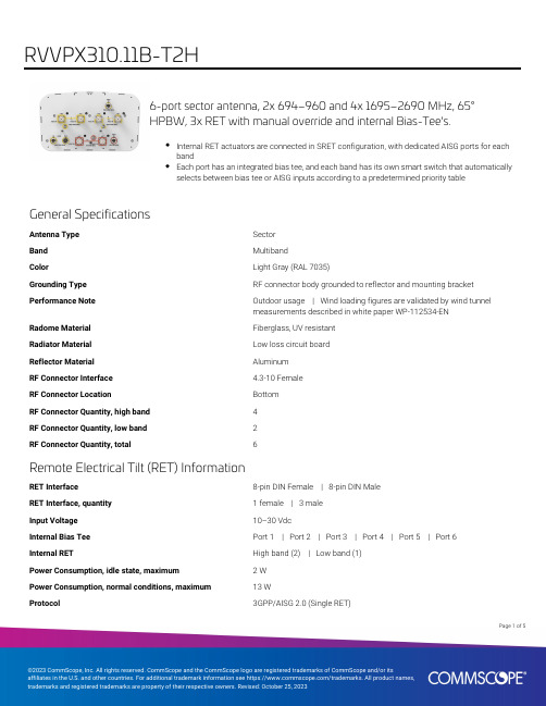
6-port sector antenna, 2x 694–960 and 4x 1695–2690 MHz, 65°HPBW, 3x RET with manual override and internal Bias-Tee's.Internal RET actuators are connected in SRET configuration, with dedicated AISG ports for eachbandEach port has an integrated bias tee, and each band has its own smart switch that automaticallyselects between bias tee or AISG inputs according to a predetermined priority tableGeneral SpecificationsAntenna Type SectorBand MultibandColor Light Gray (RAL 7035)Grounding Type RF connector body grounded to reflector and mounting bracket Performance Note Outdoor usage | Wind loading figures are validated by wind tunnelmeasurements described in white paper WP-112534-ENRadome Material Fiberglass, UV resistantRadiator Material Low loss circuit boardReflector Material AluminumRF Connector Interface 4.3-10 FemaleRF Connector Location BottomRF Connector Quantity, high band4RF Connector Quantity, low band2RF Connector Quantity, total6Remote Electrical Tilt (RET) InformationRET Interface8-pin DIN Female | 8-pin DIN MaleRET Interface, quantity 1 female | 3 maleInput Voltage10–30 VdcInternal Bias Tee Port 1 | Port 2 | Port 3 | Port 4 | Port 5 | Port 6Internal RET High band (2) | Low band (1)Power Consumption, idle state, maximum 2 WPower Consumption, normal conditions, maximum13 WProtocol3GPP/AISG 2.0 (Single RET)15Page ofPage of 25DimensionsWidth 350 mm | 13.78 in Depth 208 mm | 8.189 in Length2533 mm | 99.724 in Net Weight, without mounting kit33.2 kg | 73.193 lbArray LayoutPort ConfigurationElectrical SpecificationsImpedance50 ohmOperating Frequency Band1695 – 2690 MHz | 694 – 960 MHzPolarization±45°Total Input Power, maximum1,000 W @ 50 °CElectrical SpecificationsFrequency Band, MHz694–790790–890890–9601695–18801850–19901920–21802300–2690Gain, dBi16.316.716.917.517.918.118.669676462606261Beamwidth, Horizontal,degreesBeamwidth, Vertical, degrees10.18.98.27.67.1 6.6 5.5Beam Tilt, degrees0–100–100–100–100–100–100–10USLS (First Lobe), dB18181818181818Null Fill, dB-22-22-22-22-22-22-22Front-to-Back Ratio at 180°,29323133423839dB28282830303030Isolation, Cross Polarization,dBIsolation, Inter-band, dB30303030303030VSWR | Return loss, dB 1.5 | 14.0 1.5 | 14.0 1.5 | 14.0 1.5 | 14.0 1.5 | 14.0 1.5 | 14.0 1.5 | 14.0PIM, 3rd Order, 2 x 20 W, dBc-150-150-150-150-150-150-150200200200175175175175Input Power per Port at 50°C,maximum, watts35Page ofElectrical Specifications, BASTAFrequency Band, MHz694–790790–890890–9601695–18801850–19901920–21802300–2690 Gain by all Beam Tilts,average, dBi1616.516.817.117.617.818.2Gain by all Beam TiltsTolerance, dB±0.5±0.2±0.1±0.4±0.4±0.3±0.5Gain by Beam Tilt, average, dBi 0 ° | 16.05 ° | 16.010 ° | 15.90 ° | 16.55 ° | 16.510 ° | 16.50 ° | 16.95 ° | 16.910 ° | 16.80 ° | 17.05 ° | 17.110 ° | 17.20 ° | 17.65 ° | 17.610 ° | 17.60 ° | 17.85 ° | 17.810 ° | 17.80 ° | 18.35 ° | 18.310 ° | 18.1Beamwidth, HorizontalTolerance, degrees±1±1.1±1.8±2.5±1.4±2.5±5.6Beamwidth, VerticalTolerance, degrees±0.7±0.4±0.3±0.4±0.3±0.5±0.4USLS, beampeak to 20° abovebeampeak, dB18181818181818Front-to-Back Total Power at180° ± 30°, dB26262527292729CPR at Boresight, dB15161619202120CPR at Sector, dB12121413121211Mechanical SpecificationsWind Loading @ Velocity, frontal445.0 N @ 150 km/h (100.0 lbf @ 150 km/h)Wind Loading @ Velocity, lateral379.0 N @ 150 km/h (85.2 lbf @ 150 km/h)Wind Loading @ Velocity, maximum942.0 N @ 150 km/h (211.8 lbf @ 150 km/h)Wind Loading @ Velocity, rear472.0 N @ 150 km/h (106.1 lbf @ 150 km/h)Wind Speed, maximum241 km/h (150 mph)Packaging and WeightsWidth, packed456 mm | 17.953 inDepth, packed357 mm | 14.055 inLength, packed2834 mm | 111.575 inWeight, gross50 kg | 110.231 lbRegulatory Compliance/CertificationsAgency ClassificationCHINA-ROHS Above maximum concentration valueISO 9001:2015Designed, manufactured and/or distributed under this quality management systemROHS Compliant/ExemptedPage of45UK-ROHSCompliant/ExemptedIncluded ProductsT-029-GL-E–Adjustable Tilt Pipe Mounting Kit for 2.362"-4.5" (60-115mm) OD round members for panelantennas. Includes 2 clamp sets.* FootnotesPerformance Note Severe environmental conditions may degrade optimum performancePage of55。
818000157 (USS RF插座,III代,H0.85mm,四焊脚, 外壳镀银)_E(2)

5.2 Salt spray(盐雾试验) 5.3 Solder-ability(可焊性)
temperature:35℃ concentration:5% duration:48 hours
温度:35℃ 浓度:5% 持续时间:48 hours More than 95% of the dipped surface shall be wet. 吃锡面积 95%以上
3.3.1 Inner Contact(内导体)
3.3.2 Outer Contact(外导体)
3.4 VSWR(电压驻波比)
≦3GHz1.3 max源自3.4.1Test Method(测试方法):
NA
500 MΩ 200V AC for 1 minute
Initial(初始): After(测试后): Initial(初始): After(测试后):
6 cycles in each X-Y-Z axis
加速度735m/s2,持续时间11 ms,波型为半正弦波,3个轴向各6个循环
4.3 Vibration(振动)
Frequency:10~100Hz, half amplitude: 1.5mm, acceleration: 59m/s2. 3 mutually perpendicular direction,5 cycles in each direction 频率:10~100Hz,单向幅度 1.5mm,加速度:59m/s2,3 个轴向各 5 个循 环
ECT
Electric Connector Technology CO.,LTD
深圳市电连精密技术有限公司
Product Specification DOC. No.: 651-0157-01 Rev.: E
1.25mm端子规格书

最大值 5 毫欧 5 milliohm MAX.
只根据 PC 修订
REVISE ON PC ONLY
B
版本 REV.
见 1/9 页 SEE SHEET 1 OF 9 描述 DESCRIPTION
标题 TITLE: 1.25 间距线对板连接器产品规格书 1.25mm PITCH WIRE TO BOARD SMT CONNECTOR 本文件所含的信息属 BOOMELE 公司所有,没有书面同意其他人不得使用 THIS DOCUMENT CONTAINS INFORMATION THAT IS PROPRIETARY TO BOOMELE INC. AND SHOULD NOT BE USED WITHOUT WRITTEN PERMISSION
4-2-1
4-2-2
固定压好线的端子,以每分钟 25+3mm 的速度沿 着轴线拔出线 Fix the crimped terminal, apply axial pull out force on the wire at the speed rate of 25 3mm/minute. 将已经压好线对端子插入胶壳 Insert the crimped terminal into the housing
规格确认栏
SPECIFICATION FOR APPROVAL 客 户(CUSTOMER): 品 名(ARTICLE): 客户型号(YOUR MODEL No.): 客户料号(YOUR PART No.): 博穆型号(OUR MODEL No.): 博穆料号(OUR PART No.):
1.25T SERIESEN-37-1(019)语言 LANGUAGE
PRODUCT SPECIFICATION
RF Cable Assemblies 型号参考说明书

AEROspaceAUTOMOTIVEDEFENSEINDUSTRIALINSTRUMENTATIONSPACETELECOMMEDICAL101, Rue Ph. Hoffmann93116 ROSNY sous BOIS (Paris)Tel.: +33 1 49 35 35 35 - Fax: +33 1 48 54 63 63 E-Mail: info @P.O. Box 202 - 90101 OULU Tel.: +358 407 522 412 E-Mail: infofi @Carl-Zeiss Str. 10 Postfach 200143 D63307 - RÖDERMARK (Frankfurt)Tel.: +49 60 74 91 07 0 - Fax: +49 60 74 91 07 70 E-Mail: infode @Via Concordia, 5 - 20090 ASSAGO MILANO Tel.: +39 02 48 85 121 - Fax: +39 02 48 84 30 18 E-Mail: infoit @ Regional office: RomaHogebrinkerweg 15b - 3871 KM HOEVELAKEN Tel.: +31 33 253 40 09 - Fax: +31 33 253 45 12 E-Mail: infonl @Sjöängsvägen 2 - SE-192 72 SOLLENTUNA (Stockholm) Tel.: +46 844 434 10 - Fax: +46 875 449 16 E-Mail: infose @Ground Floor, 6 The Grand Union Office Park, Packet Boat LaneUXBRIDGE Middlesex UB8 2GH (London)Tel.: +44 1895 425 000 - Fax: +44 1895 425 010 E-Mail: infouk @6825 West Galveston Street CHANDLER, Arizona 85226Tel.: +1 480 682 9400 - Fax: +1 480 682 9403 E-Mail: infousa @N° 390 Yong He Road 200072 - SHANGHAITel.: +86 21 66 52 37 88 - Fax: +86 21 66 52 11 77 E-Mail: infosh @Shibuya-ku Ebisu 1-5-2, Kougetsu Bldg 405 TOKYO 150-0013Tel.: +81 3 3440 6241 - Fax: +81 3 3440 6242 E-Mail: infojp @Flat D, 6/F Ford Glory Plaza, 37-39 Wing Hong Street Cheung Sha WanKOWLOON HONG KONGTel: +852-2959-3833 - Fax:+852-2959-2636 E-Mail: infohk @25 D, II Phase, Peenya Industrial Area BANGALORE 560058Tel.: +91 80 83 95 271 - Fax: +91 80 83 97 228 E-Mail: infoin @For the above countries, please contact the local agent or RADIALL at info @ALSO REPRESENTED INRadiall Navigator ™ is a tool designed to assist our partners and customers that provides instant access to the right information at the right moment. This tool is intended to make sharing information about Radiall products as easy as possible in one single document.With this in mind, we have created Radiall Navigator as a supplemental guide toinformation available in our catalogs and on our website (). We recognize that time is a very limited and valuable asset. We are confident that Radiall Navigator will help users understand our products, terminologies, and references better .JacketDielectric/insulatorCorrugated ($$$$)LengthConnector 1Boot 1Coax cable Marking Sleeve 2Connector 2Length"Pigtail" AssemblyRF Cable AssembliesRight angle onlyNOTE: S = Single Brand D = Dual Brand | For more information about cables manufactured by Radiall, please visit or contact your Radiall sales representative.The following table is intended as a guideline only. For detailed specifications, please refer to the relevant or to the standard cable manufacturer’s specifications. All dimensions are nominal unless otherwise noted.。
CommScope 10-口扇区天线产品说明书
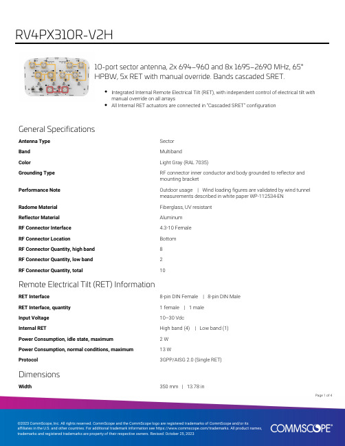
10-port sector antenna, 2x 694–960 and 8x 1695–2690 MHz, 65°HPBW, 5x RET with manual override. Bands cascaded SRET.Integrated Internal Remote Electrical Tilt (RET), with independent control of electrical tilt withmanual override on all arraysAll Internal RET actuators are connected in “Cascaded SRET” configurationGeneral SpecificationsAntenna Type SectorBand MultibandColor Light Gray (RAL 7035)Grounding Type RF connector inner conductor and body grounded to reflector andmounting bracketPerformance Note Outdoor usage | Wind loading figures are validated by wind tunnelmeasurements described in white paper WP-112534-ENRadome Material Fiberglass, UV resistantReflector Material AluminumRF Connector Interface 4.3-10 FemaleRF Connector Location BottomRF Connector Quantity, high band8RF Connector Quantity, low band2RF Connector Quantity, total10Remote Electrical Tilt (RET) InformationRET Interface8-pin DIN Female | 8-pin DIN MaleRET Interface, quantity 1 female | 1 maleInput Voltage10–30 VdcInternal RET High band (4) | Low band (1)Power Consumption, idle state, maximum 2 WPower Consumption, normal conditions, maximum13 WProtocol3GPP/AISG 2.0 (Single RET)DimensionsWidth350 mm | 13.78 in14Page ofPage of 24Depth 208 mm | 8.189 in Length2533 mm | 99.724 inArray LayoutPort ConfigurationElectrical SpecificationsImpedance50 ohmOperating Frequency Band 1695 – 2690 MHz | 694 – 960 MHz Polarization±45°Total Input Power, maximum1,000 W @ 50 °CElectrical SpecificationsFrequency Band, MHz694–798790–894890–9601695–18801850–19901920–22002300–2690 Gain, dBi1616.616.916.816.917.218 Beamwidth, Horizontal,degrees69686663626361Beamwidth, Vertical, degrees9.98.78.18.37.77.16Beam Tilt, degrees0–100–100–100–100–100–100–10 USLS (First Lobe), dB18181818181818Null Fill, dB-22-22-22-22-22-22-22Front-to-Back Ratio at 180°,dB31343332393738Isolation, Cross Polarization,dB28282830303030 Isolation, Inter-band, dB30303030303030VSWR | Return loss, dB 1.5 | 14.0 1.5 | 14.0 1.5 | 14.0 1.5 | 14.0 1.5 | 14.0 1.5 | 14.0 1.5 | 14.0 PIM, 3rd Order, 2 x 20 W, dBc-150-150-150-150-150-150-150Input Power per Port at 50°C,maximum, watts200200200175175175175 Electrical Specifications, BASTAFrequency Band, MHz694–798790–894890–9601695–18801850–19901920–22002300–2690 Gain by all Beam Tilts,average, dBi15.816.416.816.316.616.917.6Gain by all Beam TiltsTolerance, dB±0.4±0.3±0.2±0.5±0.4±0.4±0.5Gain by Beam Tilt, average, dBi 0 ° | 15.95 ° | 15.810 ° | 15.80 ° | 16.45 ° | 16.410 ° | 16.40 ° | 16.75 ° | 16.710 ° | 16.80 ° | 16.35 ° | 16.310 ° | 16.40 ° | 16.65 ° | 16.610 ° | 16.70 ° | 16.95 ° | 17.010 ° | 16.90 ° | 17.65 ° | 17.610 ° | 17.4Beamwidth, HorizontalTolerance, degrees±1.3±0.7±1.4±2.3±1.8±2.7±5.2Beamwidth, VerticalTolerance, degrees±0.7±0.5±0.3±0.5±0.3±0.5±0.4USLS, beampeak to 20° abovebeampeak, dB18181818181818Front-to-Back Total Power at180° ± 30°, dB26272726292729CPR at Boresight, dB16181717211918CPR at Sector, dB12131613121210Page of34Mechanical SpecificationsWind Loading @ Velocity, frontal445.0 N @ 150 km/h (100.0 lbf @ 150 km/h) Wind Loading @ Velocity, lateral379.0 N @ 150 km/h (85.2 lbf @ 150 km/h) Wind Loading @ Velocity, maximum942.0 N @ 150 km/h (211.8 lbf @ 150 km/h) Wind Loading @ Velocity, rear472.0 N @ 150 km/h (106.1 lbf @ 150 km/h) Wind Speed, maximum241 km/h (150 mph)Packaging and WeightsWidth, packed456 mm | 17.953 inDepth, packed357 mm | 14.055 inLength, packed2834 mm | 111.575 inWeight, gross55.3 kg | 121.915 lbWeight, net38.3 kg | 84.437 lbRegulatory Compliance/CertificationsAgency ClassificationCHINA-ROHS Above maximum concentration valueISO 9001:2015Designed, manufactured and/or distributed under this quality management system REACH-SVHC Compliant as per SVHC revision on /ProductCompliance ROHS Compliant/ExemptedUK-ROHSCompliant/ExemptedIncluded ProductsT-029-GL-E–Adjustable Tilt Pipe Mounting Kit for 2.362"-4.5" (60-115mm) OD round members for panelantennas. Includes 2 clamp sets.* FootnotesPerformance Note Severe environmental conditions may degrade optimum performancePage of44。
CommScope 面板天线安装说明书
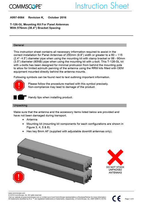
GeneralThis instruction sheet contains all necessary information required to assist in thecorrect installation for Panel Antennas of 250mm (9.8”) width or greater to a 60 – 115 (2.4”- 4.5”) diameter pipe when using the mounting kit with clamp bracket or 88 - 90mm (3.5”) diameter (80NB) pipe when using the mounting kit with u-bolt. This T-126-GL kit with u-bolts has been designed for minimal protrusion from behind the mounting pole to allow for limited azimuth panning of the antenna using the RRM kits fitted with OEM equipment mounted directly behind the antenna mounts.Following symbols can be found next to text outlining important information.Please follow the procedure marked with this symbol precisely. Non-compliance may lead to damage of the product.Handy tips when installing product.UnpackingMake sure that the antenna and the accessory items listed below are provided and have not been damaged during transport.∙ Antenna∙ Mounting kit (mounting kit components for each configurations are shown in Figure 3, 4, 5 & 6).∙ Hex key 6mm AF (supplied with adjustable downtilt antennas only).DO NOT STACK UNPACKED ANTENNASA997-0084DO NOT PLACEPOINT LOADS ON ANTENNA RADOMEInstallation InstructionsEnsure a torque spanner is used when tightening fasteners, see themounting kit diagrams on the following pages for the correct torque recommendations.Ensure antenna is installed with the connectors at the bottom.DO NOT USE ROPE OR CHAIN OR SLINGATTACHMENT AROUND ANTENNAFOR LIFTINGUSE MOUNTINGBRACKETS FOR LIFTING ASSHOWNA997-0084Installation Instructions – Adjustable Downtilt Mounting Kit T-126-GL, Bracket Spacing 976mm (38.4")Assemble mounting kits as per Figure 3, 4, 5 & 6 of this document.1. Attach the mounting kit assembly to the antenna, before trying to clamp the brackets to the pole.2. Downtilt angles of 0︒ through to 12︒ in 2︒ increments can be obtained with the correct adjustment of the tilt arm bracket.∙ 2︒- 12︒ downtilt can be achieved by aligning the corresponding hole in the tilt arm to the pivot bracket which mates against the mounting pole, as shown in Figure 7. The first vacant hole is for 2︒ downtilt, with each consecutive hole resulting in an increased inclination of 2︒.∙ For finer downtilt angle adjustments the distance in between the top and bottom mounting bracket on the pole can be adjusted.∙ For 0︒ downtilt the tilt arm may be stowed as show in Figure 7. ∙ Inclinometer or other angular measuring devices may be used toverify downtilt angle as required.The clamp brackets can clamp pipe diameters between 50 mm (2") & 115mm (4.5"). For typical installations of antennas up to 1575mm (62") long theminimum recommended pipe diameter is 60mm (2.4"). For antennas over 1575mm (62") long the minimum recommended pipe diameter is 75mm (3").Upper Mounting Bracket Assembly( To Suit Pipes OD 60-115 mm)Lower Mounting Bracket Assembly (To Suit Pipes OD 60-115 mm)Figure 1: Correctly Assembled Mounting Kit Using Clamp Bracket for Adjustable Downtilt AntennaDo not install near power lines. Power lines, telephone lines, and guy wires look the same. Assume any wire or line can electrocute you. Do not install on a wet or windy day or when lightning or thunder is in the area. Do not use metal ladder. Wear shoes with rubber soles and heels. Wear protective clothing including a long-sleeved shirt and rubber gloves.A997-0084Upper Mounting Bracket Assembly(To Suit Pipes OD 88-90 mm (80 NB))Lower Mounting Bracket Assembly(To Suit Pipes OD 88-90 mm (80 NB))Figure 2: Correctly Assembled Mounting Kit Using U-bolt for MechanicallyAdjustable Downtilt AntennaFigure 3: Exploded Assembly for Upper Mounting Bracket using Clamp Bracket Figure 4: Exploded Assembly for Upper Mounting Bracket using U-bolt(30ft.lb)A997-0084Figure 5: Exploded Assembly for Lower Mounting Bracket using Clamp Bracket (This configuration should also be used for the upper Mounting Bracket when 0° tilt is required)Figure 6: Exploded Assembly for Lower Mounting Bracket using U-bolt (This configuration should also be used for the upper Mounting Bracket when 0° tilt is required)Figure 7: Upper Bracket Placement for Various Downtilts(28ft.lb)A997-0084Operation of AntennasFixed DowntiltAntennasThe beam downtilt is factory set.Manual Electrically Adjustable Downtilt Antennas The beam downtilt below the horizon is adjusted by rotating the hex socket located at the bottom of the antenna - Figure 8). Turning the hex socket in a clockwise direction increases the beam downtilt below the horizon. Turning the hex socket in an anti-clockwise direction decreases the beam downtilt below the horizon. Beam downtilt setting in degrees below boresight can be read off the scale at the base of the antenna. The downtilt setting is read from the face of the antenna base plate at the point where the scale protrudes.AISG Compliant Remotely Adjustable Downtilt Antennas AISG Compliant antennas are compatible with AISG compliant controlunit equipment. For operation of downtilt using AISG compliant controllers see the controller documentation.WARNING: During downtilt adjustment ensure the hex socket is notturned past the minimum and maximum positions as shown on thedowntilt indicator scale. Forcing the hex adjustment beyond thispoint may lead to damage of the downtilt mechanism. Using powerdrills and electric screwdrivers to adjust downtilt may also leadto damage of the downtilt mechanism.Remote ElectricalTilt ConnectionThe AISG connector fitted to the antenna is designed to accept anyAISG compliant cable assembly. After ensuring both connectors aredry, push in the mating connector, then hand tighten.Using excessive torque may damage the AISG connection in theantenna.RF CableConnectionThe RF female connectors fitted to the antenna are designed to fitjumper cables with a corresponding male connector. After ensuringboth mating connectors are dry push the male connector in andtighten the connector coupling to the correct torque setting.If needed or as required by local procedures a weatherproofing kitmay then be fitted to the connection.If the RF connectors are tightened beyond the recommend torquethe RF connection to the antenna may be damaged.A997-0084ADJUSTING MECHANICAL DOWN TILT AFTER INSTALLATIONT-126-GL1. Use a tether to secure the antenna’s hoisting eye to the mountingstructure. The tether can be a rope, wire rope, chain, or similar material. The tether should be short enough to prevent the antenna from tilting beyond its maximum downtilt range. This will prevent the antenna from tilting away from the mounting structure when the adjusting bolts are removed.Installed cables or the antenna may be damaged if they are allowed to strike the mounting structure when the antenna mechanical downtilt is changed.Figure 10: Upper Mounting Bracket Assembly2. Loosen the fasteners holding the bottom antenna bracket to the bottom pivot bracket. Do not remove them.Figure 11: Lower Mounting Bracket AssemblyLoosen the FastenersA997-00843. Remove the M12 bolts, washers, and nuts from the pivot bracket. Theantenna may tilt down to the extent allowed by the tether installed in step 1.Figure 12: Upper Mounting Bracket Assembly4. The desired downtilt angle may be obtained with the correct adjustment of the tilt arm bracket. See the installation instructions above for detailed information.5. Adjust the antenna downtilt to the desired angle and reinstall the M12 bolts, washers, and nuts between the upper pivot bracket and the tilt arm.6. Tighten all four M12 nuts to 38Nm (28 ft.lb).7.Remove the tether.Remove the Fasteners。
北斗 GPS陶瓷天线商品说明书

承认厂商:(Recognized制造厂商(Manufacturer)产品名称:北斗\GPS陶瓷天线(Description)产品选型表:(Product Type)型号说明备注BWGPSCNX8-8AL120焊接接口线长120mm参数均可订制BWGPSCNX8-8B1L120IPEX1接口线长120mm参数均可订制BWGPSCNX8-8B4L120IPEX4接口线长120mm参数均可订制供应商承认签栏制表者审核者核准者客户承认栏审核者核准者*注:以上数据仅供参考;因天线功能较为敏感,主体周边机构有变更请通知我们评估。
1.2AntennaPicture(定制客户中间连接线长度定制,天线形状定制)*注:因天线功能较为敏感,主体周边机构有变更请通知我们评估。
上图型号:BWGPSCNX8-8B12.Electrical S pecification2.1Test EquipmentA.VSWR and input impedance:Agilent8753/E5071Network AnalyzerB.Antenna gain and efficiency:ETS three-dimensional anechoic chamber2.2Test Setup2.2.1Frequency Range2.2.2VSWRStep1:The antenna is arranged on the customer provided test fixture.Step2:The VSWR of the antenna is measured via Agilent8720/8753Network Analyzer(see figure.1).Figure.12.2.3Radiation pattern and GainA.The3D chamber provides less than-40dB reflectivity from800MHz to6GHz and a40cm diameterspherical quiet zone.The measurement results are calibrated using both dipoles and standard gainhorns(see figure.2).B.The antenna under tested is arranged in the turned table and a decoupling sleeve is used to reducefeed line radiation(see figure.3).C.The measured results of the radiation patterns and antenna gain are obtained from the controlsystem and showed on the monitor(see figure.4and5).Figure.2Figure.3Figure.4Figure.53.Performance Data3.1Passive dataVSWR(电压驻波比)/Return Loss(回波损耗)/Smith Chart(史密斯圆图)*注:以上为实测数据,仅供参考;因天线功能较为敏感,主体周边机构有变更请通知我们评估。
CommScope 5-4端口多腿天线(2023年版)说明书

4-port multibeam antenna, 4x 790–960 MHz, 2x 38° HPBW, 2x RETwith manual override.Integrated Internal Remote Electrical Tilt (RET), with independent control of electrical tilt withmanual override on all arraysSingle panel design supporting two separate beams perfectly optimized at horizontal pointingangles of +27 degrees and –27 degrees from boresightOBSOLETEThis product was discontinued on: November 30, 2023General SpecificationsAntenna Type MultibeamBand Single bandColor Light Gray (RAL 7035)Grounding Type RF connector inner conductor and body grounded to reflector andmounting bracketPerformance Note Outdoor usageRadome Material Polyester fiberglass pultrusionRadiator Material Low loss circuit boardReflector Material AluminumRF Connector Interface7-16 DIN FemaleRF Connector Location BottomRF Connector Quantity, low band4RF Connector Quantity, total4Remote Electrical Tilt (RET) InformationRET Interface8-pin DIN Female | 8-pin DIN MaleRET Interface, quantity 1 female | 1 maleInput Voltage10–30 VdcInternal RET Low band (2)Power Consumption, idle state, maximum 2 WPower Consumption, normal conditions, maximum13 W15Page ofProtocol3GPP/AISG 2.0 (Single RET) DimensionsWidth504 mm | 19.843 in Depth118 mm | 4.646 in Length2090 mm | 82.284 inNet Weight, without mounting kit32.5 kg | 71.65 lb Electrical SpecificationsImpedance50 ohmOperating Frequency Band790 – 960 MHz Polarization±45°Electrical SpecificationsFrequency Band, MHz790–890890–960 Gain, dBi18.118.6 Beam Centers, Horizontal, degrees±27±27 Beamwidth, Horizontal, degrees4035 Beamwidth, Vertical, degrees109.1 Beam Tilt, degrees0–100–10 USLS (First Lobe), dB1818Null Fill, dB-22-22 Front-to-Back Ratio at 180°, dB3231 Front-to-Back Ratio, Copolarization 180° ± 30°,dB2623 Isolation, Same Beam, dB2525 VSWR | Return loss, dB 1.29 | 18.0 1.29 | 18.0 PIM, 3rd Order, 2 x 20 W, dBc-150-150 Input Power per Port, maximum, watts300300 Electrical Specifications, BASTAFrequency Band, MHz790–890890–960 Gain by all Beam Tilts, average, dBi17.818.3 Gain by all Beam Tilts Tolerance, dB±0.4±0.3Gain by Beam Tilt, average, dBi0 ° | 17.95 ° | 17.910 ° | 17.80 ° | 18.45 ° | 18.410 ° | 18.1Page of25Page of 35Beamwidth, Horizontal Tolerance, degrees ±2.3±2.2Beamwidth, Vertical Tolerance, degrees ±0.5±0.4USLS, beampeak to 20° above beampeak, dB 2122Front-to-Back Total Power at 180° ± 30°, dB 2320CPR at Boresight, dB 2321CPR at Sector, dB127Mechanical SpecificationsWind Loading @ Velocity, frontal 1,352.0 N @ 150 km/h (303.9 lbf @ 150 km/h)Wind Loading @ Velocity, lateral 228.0 N @ 150 km/h (51.3 lbf @ 150 km/h)Wind Loading @ Velocity, rear 1,379.0 N @ 150 km/h (310.0 lbf @ 150 km/h)Wind Speed, maximum200 km/h (124 mph)Packaging and WeightsWidth, packed 593 mm | 23.346 in Depth, packed 209 mm | 8.228 in Length, packed 2229 mm | 87.756 in Weight, gross45.5 kg | 100.31 lbRegulatory Compliance/CertificationsAgency ClassificationCECompliant with the relevant CE product directives CHINA-ROHS Above maximum concentration valueISO 9001:2015Designed, manufactured and/or distributed under this quality management system ROHS Compliant/Exempted UK-ROHSCompliantIncluded ProductsT-029-GL-E–Adjustable Tilt Pipe Mounting Kit for 2.362"-4.5" (60-115mm) OD round members for panel antennas. Includes 2 clamp sets.* FootnotesPerformance NoteSevere environmental conditions may degrade optimum performanceAdjustable Tilt Pipe Mounting Kit for 2.362"-4.5" (60-115mm) OD roundmembers for panel antennas. Includes 2 clamp sets.Product ClassificationProduct Type Adjustable tilt mounting kitGeneral SpecificationsApplication OutdoorColor SilverDimensionsCompatible Length, maximum2850 mm | 112.205 inCompatible Length, minimum1500 mm | 59.055 inCompatible Diameter, maximum115 mm | 4.528 inCompatible Diameter, minimum60 mm | 2.362 inAntenna-to-Pipe Distance85 mm | 3.346 inBracket-to-Bracket Distance1400 mm | 55.118 inWeight, net 6 kg | 13.228 lbMaterial SpecificationsMaterial Type Galvanized steelMechanical SpecificationsMechanical Tilt0°–8°Packaging and WeightsIncluded Brackets | HardwarePackaging quantity1Regulatory Compliance/CertificationsAgency ClassificationCE Compliant with the relevant CE product directives45Page ofCHINA-ROHS Below maximum concentration valueISO 9001:2015Designed, manufactured and/or distributed under this quality management system REACH-SVHC Compliant as per SVHC revision on /ProductCompliance ROHS CompliantUK-ROHSCompliantPage of55。
CommScope 10-口扇形抗干扰天线说明书
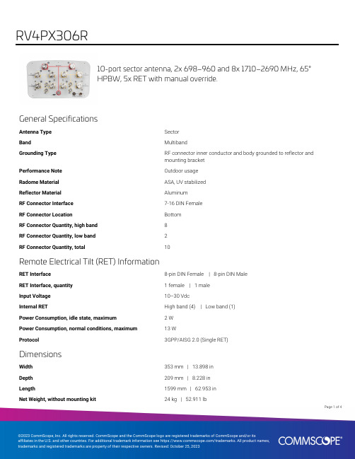
10-port sector antenna, 2x 698–960 and 8x 1710–2690 MHz, 65°HPBW, 5x RET with manual override.General SpecificationsAntenna Type SectorBand MultibandGrounding Type RF connector inner conductor and body grounded to reflector andmounting bracketPerformance Note Outdoor usageRadome Material ASA, UV stabilizedReflector Material AluminumRF Connector Interface7-16 DIN FemaleRF Connector Location BottomRF Connector Quantity, high band8RF Connector Quantity, low band2RF Connector Quantity, total10Remote Electrical Tilt (RET) InformationRET Interface8-pin DIN Female | 8-pin DIN MaleRET Interface, quantity 1 female | 1 maleInput Voltage10–30 VdcInternal RET High band (4) | Low band (1)Power Consumption, idle state, maximum 2 WPower Consumption, normal conditions, maximum13 WProtocol3GPP/AISG 2.0 (Single RET)DimensionsWidth353 mm | 13.898 inDepth209 mm | 8.228 inLength1599 mm | 62.953 inNet Weight, without mounting kit24 kg | 52.911 lb14Page ofPage of 24Array LayoutElectrical SpecificationsImpedance50 ohmOperating Frequency Band 1710 – 2690 MHz | 698 – 960 MHz Polarization±45°Electrical SpecificationsFrequency Band, MHz 698–790790–890890–9601710–19201920–21802300–2690Gain, dBi14.214.414.914.715.216.1Beamwidth, Horizontal, degrees68696363636216.414.913.613.712.29.7Beamwidth, Vertical, degrees16.414.913.613.712.29.7Beam Tilt, degrees0–100–100–100–100–100–10 USLS (First Lobe), dB181818181818Null Fill, dB-22-22-22-22-22-22Front-to-Back Ratio at 180°,dB232323272828CPR at Boresight, dB161212171514CPR at Sector, dB886532 Isolation, Cross Polarization,dB252525252525 Isolation, Inter-band, dB303030303030VSWR | Return loss, dB 1.43 | 15.0 1.43 | 15.0 1.43 | 15.0 1.5 | 14.0 1.5 | 14.0 1.5 | 14.0 PIM, 3rd Order, 2 x 20 W, dBc-150-150-150-150-150-150Input Power per Port,maximum, watts300300300250250250 Electrical Specifications, BASTAFrequency Band, MHz698–790790–890890–9601710–19201920–21802300–2690 Gain by all Beam Tilts,average, dBi1414.214.614.61515.8Gain by all Beam TiltsTolerance, dB±0.2±0.2±0.3±0.5±0.4±0.5Gain by Beam Tilt, average, dBi 0 ° | 14.05 ° | 14.010 ° | 14.00 ° | 14.25 ° | 14.210 ° | 14.10 ° | 14.65 ° | 14.610 ° | 14.60 ° | 14.65 ° | 14.610 ° | 14.60 ° | 15.05 ° | 15.010 ° | 15.10 ° | 16.05 ° | 15.810 ° | 15.6Beamwidth, HorizontalTolerance, degrees±1.4±1.2±1.6±2.5±3.5±6.4Beamwidth, VerticalTolerance, degrees±0.8±0.8±0.5±0.9±1±0.9USLS, beampeak to 20° abovebeampeak, dB181818181818Front-to-Back Total Power at180° ± 30°, dB252323232525CPR at Boresight, dB171313201718CPR at Sector, dB10108754Mechanical SpecificationsWind Loading @ Velocity, frontal681.0 N @ 150 km/h (153.1 lbf @ 150 km/h)Wind Loading @ Velocity, lateral265.0 N @ 150 km/h (59.6 lbf @ 150 km/h)Wind Loading @ Velocity, rear699.0 N @ 150 km/h (157.1 lbf @ 150 km/h)Page of34Wind Speed, maximum250 km/h (155 mph)Packaging and WeightsWidth, packed427 mm | 16.811 inDepth, packed325 mm | 12.795 inLength, packed1787 mm | 70.354 inWeight, gross39 kg | 85.98 lbRegulatory Compliance/CertificationsAgency ClassificationCE Compliant with the relevant CE product directivesCHINA-ROHS Above maximum concentration valueISO 9001:2015Designed, manufactured and/or distributed under this quality management system REACH-SVHC Compliant as per SVHC revision on /ProductCompliance ROHS Compliant/ExemptedUK-ROHSCompliant/ExemptedIncluded ProductsT-041-GL-E–Adjustable Tilt Pipe Mounting Kit for 2.0"-4.5" (60-115mm) OD round members for panelantennas. Includes 2 clamp sets.* FootnotesPerformance Note Severe environmental conditions may degrade optimum performancePage of44。
CommScope 6-线扇形天线说明书

6-port sector antenna, 2x 694–960 and 4x 1695–2690 MHz, 65°HPBW, 3x RET with manual override and SBT on every RF portEach port has an integrated bias tee, and each band has its own smart switch that automaticallyselects between bias tee or AISG inputs according to a predetermined priority tableAll Internal RET actuators are in SRET configuration, with dedicated AISG ports for each bandGeneral SpecificationsAntenna Type SectorBand MultibandGrounding Type RF connector body grounded to reflector and mounting bracket Performance Note Outdoor usage | Wind loading figures are validated by wind tunnelmeasurements described in white paper WP-112534-ENRadome Material Fiberglass, UV resistantRadiator Material Low loss circuit boardReflector Material AluminumRF Connector Interface7-16 DIN FemaleRF Connector Location BottomRF Connector Quantity, high band4RF Connector Quantity, low band2RF Connector Quantity, total6Remote Electrical Tilt (RET) InformationRET Interface8-pin DIN Female | 8-pin DIN MaleRET Interface, quantity 1 female | 3 maleInput Voltage10–30 VdcInternal Bias Tee Port 1 | Port 2 | Port 3 | Port 4 | Port 5 | Port 6Internal RET High band (2) | Low band (1)Power Consumption, idle state, maximum 2 WPower Consumption, normal conditions, maximum13 WProtocol3GPP/AISG 2.0 (Single RET)Dimensions350 mm | 13.78 in15Page ofPage of 25Width 350 mm | 13.78 in Depth 208 mm | 8.189 in Length1584 mm | 62.362 in Net Weight, without mounting kit24.7 kg | 54.454 lbArray LayoutPort ConfigurationPage of 35Electrical SpecificationsImpedance50 ohmOperating Frequency Band 1695 – 2690 MHz | 694 – 960 MHz Polarization±45°650 W @ 50 °CTotal Input Power, maximum650 W @ 50 °CElectrical SpecificationsFrequency Band, MHz694–790790–890890–9601695–19201920–21802300–2690 Gain, dBi14.314.915.217.217.818.4 Beamwidth, Horizontal,degrees696766626264Beamwidth, Vertical, degrees16.514.613.67.5 6.7 5.5Beam Tilt, degrees2–122–122–120–100–100–10 USLS (First Lobe), dB151821182019Front-to-Back Ratio at 180°,dB303233363738Isolation, Cross Polarization,dB272727282828 Isolation, Inter-band, dB282828282828VSWR | Return loss, dB 1.5 | 14.0 1.5 | 14.0 1.5 | 14.0 1.5 | 14.0 1.5 | 14.0 1.5 | 14.0 PIM, 3rd Order, 2 x 20 W, dBc-150-150-150-150-150-150Input Power per Port at 50°C,maximum, watts150150150150150100 Electrical Specifications, BASTAFrequency Band, MHz694–790790–890890–9601695–19201920–21802300–2690 Gain by all Beam Tilts,average, dBi14.114.81516.917.618.2Gain by all Beam TiltsTolerance, dB±0.4±0.3±0.3±0.5±0.5±0.3Gain by Beam Tilt, average, dBi 2 ° | 14.27 ° | 14.112 ° | 14.02 ° | 14.87 ° | 14.812 ° | 14.72 ° | 15.07 ° | 15.112 ° | 15.00 ° | 16.85 ° | 16.910 ° | 16.90 ° | 17.65 ° | 17.610 ° | 17.60 ° | 18.25 ° | 18.310 ° | 18.2Beamwidth, HorizontalTolerance, degrees±1.2±1±1.6±2.9±1.9±3.2Beamwidth, VerticalTolerance, degrees±1±0.8±0.5±0.5±0.5±0.4USLS, beampeak to 20° abovebeampeak, dB181822181919Front-to-Back Total Power at180° ± 30°, dB252526292729CPR at Boresight, dB201920192019CPR at Sector, dB12121510119Page of45Mechanical SpecificationsWind Loading @ Velocity, frontal255.0 N @ 150 km/h (57.3 lbf @ 150 km/h) Wind Loading @ Velocity, lateral214.0 N @ 150 km/h (48.1 lbf @ 150 km/h) Wind Loading @ Velocity, maximum540.0 N @ 150 km/h (121.4 lbf @ 150 km/h) Wind Loading @ Velocity, rear270.0 N @ 150 km/h (60.7 lbf @ 150 km/h) Wind Speed, maximum241 km/h (150 mph)Packaging and WeightsWidth, packed420 mm | 16.535 inDepth, packed310 mm | 12.205 inLength, packed1760 mm | 69.291 inWeight, gross41.4 kg | 91.271 lbRegulatory Compliance/CertificationsAgency ClassificationCHINA-ROHS Above maximum concentration valueISO 9001:2015Designed, manufactured and/or distributed under this quality management system ROHS Compliant/ExemptedUK-ROHSCompliant/ExemptedIncluded ProductsT-041-GL-E–Adjustable Tilt Pipe Mounting Kit for 2.0"-4.5" (60-115mm) OD round members for panelantennas. Includes 2 clamp sets.* FootnotesPerformance Note Severe environmental conditions may degrade optimum performancePage of55。
NFC+WPC Combo(NFC天线+Rx接收端模组)-产品规格书
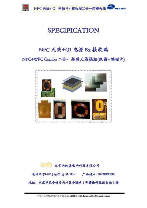
NFC 天线+QI 电源 Rx 接收端二合一超薄天线
REVISED HISTORY
南波源电子产品规格: NFC+WPC Combo 1607 产品系列
NO. REV. REVISED CONTENT 10
更多产品规格,欢迎来电咨询,电话:18938190280. Email: mtf01@
NFC 天线+QI 电源 Rx 接收端二合一超薄天线
6, 产品可靠性测试
No. Parameter
1 Low Temperature (Storage)
2 High Temperature (Storage)
2, NFC 与 WPC 线圈二合一,有效整合,方便产品空间结构设计.
3, NFC 线圈与 WPC 线圈,只需使用一片隔磁材料,降低材料成本.
4, 产品实测 NFC 读卡距离不变,WPC 充电效率达到约 70%.
二, NFC+WPC COMBO 产品组件规格:
1, 产品使用隔磁材料 ferrite sheet :
Half-sine shock (1) 200G, 3ms(Gravity) (2)
(1) Temperature : +60±2℃ (2) Humidity: 90% RAH. (3) Time: 240Hrs
(1) Height : 160cm to the concrete floor (fixture weight : 160g ) (2) Direction : 6 directions (3) Times : 3 times / direction (1) Drop the sample package in a carton box. (2) Height : 100 cm (3) Direction :1corner,3 edges, 6 faces (4) Drop time : 16 times
2.4GHz MID SMT 天线产品规格表说明书

CREATED / REVISED BY: Kang Cheng
CHECKED BY: Horace Ma
APPROVED BY: Welson Tan
TEMPLATE FILENAME: PRODUCT_SPEC[SIZE_A4](V.1).DOC
PRODUCT SPECIFICATION
TEMPLATE FILENAME: PRODUCT_SPEC[SIZE_A4](V.1).DOC
PRODUCT SPECIFICATION
3.0 APPLICABLE DOCUMENTS
DOCUMENT Sale Drawing (SD) Application Guide (AS) Packing Drawing (PK)
REVISION: ECR/ECN INFORMATION: TITLE:
G1
EC No: 763980 DATE: 2023/02/15
2.4GHZ MID SMT Antenna Product Specification
SHEET No.
1 of 11
DOCUMENT NUMBER:
PS-479480001
PRODUCT SPECIFICATION
TITLE
2.4GHZ MID SMT ANTENNA
TABLE OF CONTENTS
1.0 SCOPE 2.0 PRODUCT DESCRIPTION 3.0 APPLICABLE DOCUMENTS 4.0 GENERAL SPECIFICATION 5.0 ANTENNA SPECIFICATION 6.0 MECHANICAL REQUIREMENTS 7.0 ENVIRONMENTAL SPECIFICATION 8.0 RECOMMENDED REFLOW CONDITION 9.0 RECOMMENDED FOOTPRINT ON PCB FOR SOLDERING 10.0 PACKING 11.0 OTHER MOLEX ANTENNA PRODUCTS 12.0 CHANGED HISTORY
CommScope V4-65D-M 8-端口扇形天线产品说明书

8-port sector antenna, 8x 1710–2690 MHz, 65° HPBW, manual tilt.Employs state-of-the-art ultra wideband technology providing excellent RF performance in allbandsExcellent RF pattern control over the full operating band and tilt range for desired coverage andinterference containmentOBSOLETEThis product was discontinued on: March 31, 2021Replaced By:V4-65D-R4-V28-port sector antenna, 8x 1710–2690 MHz, 65° HPBW, 4x RET with manual override. Antenna rearwind loading 445N @ 150km/hGeneral SpecificationsAntenna Type SectorBand Single bandColor Light Gray (RAL 7035)Grounding Type RF connector inner conductor and body grounded to reflector and mounting bracket Performance Note Outdoor usage | Wind loading figures are validated by wind tunnel measurementsdescribed in white paper WP-112534-ENRadome Material Fiberglass, UV resistantRadiator Material Low loss circuit boardReflector Material AluminumRF Connector Interface7-16 DIN FemaleRF Connector Location BottomRF Connector Quantity, high band8RF Connector Quantity, total8DimensionsWidth301 mm | 11.85 inDepth180 mm | 7.087 inLength2645 mm | 104.134 inNet Weight, without mounting kit28 kg | 61.729 lb13Page ofElectrical SpecificationsImpedance50 ohmOperating Frequency Band1710 – 2690 MHzPolarization±45°Total Input Power, maximum800 W @ 50 °CElectrical SpecificationsFrequency Band, MHz1710–18801920–22002300–25002500–2690 Gain, dBi1717.818.318.9 Beamwidth, Horizontal, degrees70676054 Beamwidth, Vertical, degrees 6.9 6.3 5.5 5.2Beam Tilt, degrees0–100–100–100–10 USLS (First Lobe), dB16172020Front-to-Back Ratio at 180°, dB35374039 Isolation, Cross Polarization, dB28282828 Isolation, Inter-band, dB28282828VSWR | Return loss, dB 1.5 | 14.0 1.5 | 14.0 1.5 | 14.0 1.5 | 14.0 PIM, 3rd Order, 2 x 20 W, dBc-150-150-150-150Input Power per Port at 50°C,maximum, watts200200200200 Electrical Specifications, BASTAFrequency Band, MHz1710–18801920–22002300–25002500–2690 Gain by all Beam Tilts, average, dBi16.817.418.118.5Gain by all Beam Tilts Tolerance, dB±0.3±0.5±0.4±0.6Gain by Beam Tilt, average, dBi0 ° | 16.65 ° | 16.610 ° | 16.80 ° | 17.35 ° | 17.510 ° | 17.30 ° | 17.85 ° | 18.110 ° | 18.10 ° | 18.45 ° | 18.710 ° | 18.2Beamwidth, Horizontal Tolerance,degrees±2.7±3±4.1±2.8Beamwidth, Vertical Tolerance,degrees±0.5±0.6±0.4±0.4USLS, beampeak to 20° abovebeampeak, dB15151818Front-to-Back Total Power at 180° ±30°, dB25272827CPR at Boresight, dB15161615121265Page of23CPR at Sector, dB121265 Mechanical SpecificationsWind Loading @ Velocity, frontal433.0 N @ 150 km/h (97.3 lbf @ 150 km/h)Wind Loading @ Velocity, lateral367.0 N @ 150 km/h (82.5 lbf @ 150 km/h)Wind Loading @ Velocity, maximum834.0 N @ 150 km/h (187.5 lbf @ 150 km/h)Wind Loading @ Velocity, rear439.0 N @ 150 km/h (98.7 lbf @ 150 km/h)Wind Speed, maximum241 km/h (150 mph)Packaging and WeightsWidth, packed409 mm | 16.102 inDepth, packed309 mm | 12.165 inLength, packed2894 mm | 113.937 inWeight, gross46.5 kg | 102.515 lbRegulatory Compliance/CertificationsAgency ClassificationISO 9001:2015Designed, manufactured and/or distributed under this quality management systemIncluded ProductsBSAMNT-3–Wide Profile Antenna Downtilt Mounting Kit for 2.4 - 4.5 in (60 - 115 mm) OD round members.Kit contains one scissor top bracket set and one bottom bracket set.BSAMNT-M–Middle Downtilt Mounting Kit for Long Antennas for 2.4 - 4.5 in (60 - 115 mm) OD roundmembers. Kit contains one scissor bracket set.* FootnotesPerformance Note Severe environmental conditions may degrade optimum performancePage of33。
