DC-1500直流电机调速器说明书
洪力电能 1500系列产品说明书

!CAUTION: Caution statements indicate the conditions or practices that could result in damage to this product or other property.
DC1500V隔离开关原理与构造(精)

6.接线及安装避雷器的情况
开关柜进出线方式为下部电缆进出线。 三台柜内可接进线电缆400mm212根,出 线电缆240mm224根。 单台柜内可接进线电缆400mm28根,出线 电缆240mm212根。 电动隔离开关柜内可以根据用户要求可以 安装避雷器,三台柜安装2台避雷器,单台 柜安装1台避雷器。
WK S Y
手 动合 闸 遥 控合 闸 遥 控分 闸
X1- 8
X1-2
HA'
X1-5
闭锁 条件
FA' X1-1 HC FA FC FC XK1
合 闸 回 路 分 闸 回 路
X1-9
TA
手 动分 闸
8、操作
操作安全:为了防止误操作,必须熟悉以下功能。 用钥匙打开门后,方可进行手动操作。 手动操作必须用专用手摇柄,并且只有当压下行程开关XK后,才能插入手摇柄进行手 动操作。当压下行程开关XK后电动失效。 当地电动时,必须把“远方——当地”旋钮打到“近动”或“当地”位置,且手动摇 柄已取出。 远动操作时,必须把“远方——当地”旋钮打到“远方”位置,并关锁好设备的所有 外门和窗口。 10.1.3 操作附件:手动摇柄、打开和闭合设备外门及窗口的钥匙。 10.1.4 手动操作时,按所标示的“合——分”方向摇转手动摇柄,观察隔离开关的分合 状态,并直到被限位。 10.1.5 电动时只要按动“合闸——分闸”按钮既可。异常情况时可按“停止”按钮随 时停止操作,当异常解除时,使开关合分到位,准备下一次操作。 10.1.6 三台联放电动隔离开关柜,设有机械联锁。打开前门,在中挡板上安装了三个 限位锁,供手动调试或异常工作状态下手动调整时使用,只有获得授权的工作人员方 可取得钥匙。特别注意:当中间联络隔开合闸时,左右两侧进线隔开不能同时合闸供 电;中间联络隔开分闸时,两侧进线隔开可以独立进行分、合闸操作。
直流调速器说明书

JHX5-DM 直流调速器说明
单板型JHX5系列直流电机调速器,是根据中小型机械客户的实际要求设计开发,使用先进单片微机, 采用数字PID 的方法进行运算和控制, 并结合成熟的EMC 抗干扰措施进行优化设计, 工作性能稳定可靠, 有着很高的性价比,可广泛适用于直流电机的马达调速。
型 号 说 明:
结构及接线:
注 意 事 项:
* 不可安装在有腐蚀性气体的环境, 相对湿度90%以下, 无结露。
* 应安装在不会有水溅到的位置,无粉尘的场所. 最好安装在专用的电器箱内。
* 外壳应接地,调速器裸露的线路均可能带有高压,上电后不可触摸。
断电后,机内高压也需一定时间释放,因此检查时,要等机内LED 指示灯完全熄灭后方可进行,应放在非专业人员接触不到的位置,防止发生触电危险。
温州精汇电子科技有限公司
光电开关
JHX5 - M
H:带显示扩展功能
A: 交流电机调速器25~550W。
MA1500Amp True RMS AC DC Clamp Meter 用户手册说明书

User Manual1500Amp True RMS AC/DCClamp MeterModel MA1500IntroductionCongratulations on your purchase of this MA1500 True RMS Clamp Meter. This meter measures AC Current, DC Current, AC/DC Voltage, Resistance, Capacitance, Frequency, Diode Test, Duty Cycle and Continuity. The molded case is designed for heavy duty use. This meter is shipped fully tested and calibrated and, with proper use, will provide years of reliable service. SafetyInternational Safety SymbolsThis symbol, adjacent to another symbol or terminal, indicates the user must referto the manual for further information.This symbol, adjacent to a terminal, indicates that, under normal use, hazardousvoltages may be presentDouble insulationThis WARNING symbol indicates a potentially hazardous situation, which if not avoided, could result in death or serious injury. This CAUTION symbol indicates a potentially hazardous situation, which if not avoided, may result damage to the product.PER IEC1010 OVERVOLTAGE INSTALLATION CATEGORYOVERVOLTAGE CATEGORY IEquipment of OVERVOLTAGE CATEGORY I is equipment for connection to circuits in which measures are taken to limit the transient overvoltages to an appropriate low level.Note – Examples include protected electronic circuits.OVERVOLTAGE CATEGORY IIEquipment of OVERVOLTAGE CATEGORY II is energy-consuming equipment to be supplied from the fixed installation.Note – Examples include household, office, and laboratory appliances.OVERVOLTAGE CATEGORY IIIEquipment of OVERVOLTAGE CATEGORY III is equipment in fixed installations.Note – Examples include switches in the fixed installation and some equipment for industrial use with permanent connection to the fixed installation.OVERVOLTAGE CATEGORY IVEquipment of OVERVOLTAGE CATEGORY IV is for use at the origin of the installation.Note – Examples include electricity meters and primary over-current protection equipmentSAFETY NOTES∙Do not exceed the maximum allowable input range of any function.∙Do not apply voltage to meter when resistance function is selected.∙Set the function switch OFF when the meter is not in use.∙Remove the battery if meter is to be stored for longer than 60 days.WARNINGS∙Set function switch to the appropriate position before measuring.∙When measuring volts do not switch to current/resistance modes.∙Do not measure current on a circuit whose voltage exceeds 600V.∙When changing ranges, always disconnect the test leads from the circuit under test. CAUTIONS∙Improper use of this meter can cause damage, shock, injury or death. Read and understand this user manual before operating the meter.∙Always remove the test leads before replacing the battery or fuses.∙Inspect the condition of the test leads and the meter itself for any damage before operating the meter. Repair or replace any damage before use.∙Use great care when making measurements if the voltages are greater than 25VAC rms or 35VDC. These voltages are considered a shock hazard.∙Always discharge capacitors and remove power from the device under test before performing Diode, Resistance or Continuity tests.∙Voltage checks on electrical outlets can be difficult and misleading because of the uncertainty of connection to the recessed electrical contacts. Other means should be used to ensure that the terminals are not "live".∙If the equipment is used in a manner not specified by the manufacturer, the protection provided by the equipment may be impaired.∙This device is not a toy and must not reach children’s hands. It contains hazardous objects as well as small parts that the children could swallow. In case a child swallows any of them,please contact a physician immediately∙Do not leave batteries and packing material lying around unattended; they can be dangerous for children if they use them as toys∙Expired or damaged batteries can cause cauterization on contact with the skin. Always, therefore, use suitable hand gloves in such cases∙Do not short-circuited the battery. Do not throw batteries into a fire.Meter Description1. Current clamp2. Clamp opening trigger3. RANGE Button4. MODE button5. MAX/MIN button6. INRUSH button7. Backlit LCD Display8. Non-Contact Voltage Detector9. NCV LED indicator10. Function switch and HOLD button11. o C / o F select button12. Back light button13. ZERO button14. PEAK button15. Multimeter input jacksDisplay icons DescriptionHOLD Data HoldAPO Auto Power OffAUTO AutorangingP Peak HoldDC Direct CurrentAC Alternating CurrentMAX Max readingMIN Min readingLow batteryZERO DCA or CAP zeromV or V Milli-volts or Volts (Voltage)ΩOhms (Resistance)A Amperes (Current)F Farad (Capacitance)Hz Hertz (Frequency)% Duty Ratioo F and o C Fahrenheit and Celsius units (Temperature)n, m, μ, M, k Unit of measure prefixes: nano, milli, micro, mega, and kilo ∙))) Continuity testDiode testNon-Contact Voltage Detector1. Rotate the Function switch to any measurement position.2. Place the detector probe tip on the conductor to be tested.3. If AC voltage is present, the NCV detector will turn on with asteady red light.NOTE: The conductors in electrical cord sets are often twisted. Forbest results, move the probe tip along a length of the cord toassure placing the tip close to the live conductor.NOTE: The detector is designed with high sensitivity. Static electricityor other sources of energy may randomly trip the sensor. Thisis normal operation.AC/DC Current Measurements1. Rotate the Function switch to the 1500A AC/DC position.2. Press the MODE button to select AC or DC.3. Press the trigger to open jaw. Fully enclose only oneconductor.4. Read the current value in the display.5. If the value is less than 400A, rotate the function switch tothe 400A AC/DC position to improve resolution.DCA ZeroThe Zero feature removes offset values and improves accuracyfor DC current measurements. To perform a zero, select DC and, with no conductor in the jaw, press the ZERO button. The display will show approxemately zero. The offset value is now stored and removed from all measurements.FrequencyWhen ACA is selected, the measured frequency can be viewed in the lower display.AC/DC Voltage Measurements1. Rotate the function switch to the V position.2. Press the MODE button to select AC or DC Voltage.3. Insert the black test lead banana plug into the negative COM jack.Insert the red test lead banana plug into the positive V jack.4. Touch the black test probe tip to the negative side of the circuit.Touch the red test probe tip to the positive side of the circuit.5. Read the voltage value in the display.FrequencyWhen ACV is selected, the measured frequency can be viewed in thelower display.Resistance MeasurementsNote: Remove power from the device under test before measuring resistance.1. Set the function switch to the Ω position.2. Insert the black test lead banana plug into the negative COM jack.Insert the red test lead banana plug into the positive V jack.3. Touch the black test probe tip to one side of the device to be measured.Touch the red test probe tip to the other side of the device to be measured.4. Read the resistance value in the display.Continuity Test1. Set the function switch to the ∙))) position.2. Insert the black test lead banana plug into the negative COM jack.Insert the red test lead banana plug into the positive V jack.3. Press the MODE button to select ∙))) (continuity).4. Touch the test probe tips across the circuit or component under test.5. If the resistance is less than the continuity threshold,a tone will sound.Diode Test1. position.2. Insert the black test lead banana plug into the negative COM jack.Insert the red test lead banana plug into the positive V jack.3. Press the MODE4. Touch the test probe tips to the diode or semiconductor junction under test. Note the meterreading.5. Reverse the test lead polarity by reversing the red and black leads. Note this reading.6. The diode or junction can be evaluated as follows:▪If one reading displays a value (typically 0.400V to 01.800V) and the other reading displays OL, the diode is good.▪If both readings display OL the device is open.If both readings are very small or ‘0’, the device is shorted.1. Set the function switch to the CAP position.2. Insert the black test lead banana plug into the negative COM jack.Insert the red test lead banana plug into the positive jack.3. Press the MODE button to select capacitance (μF) measurements.4. Touch the black test probe tip to one side of the device.Touch the red test probe tip to the other side of the device.5. Read the capacitance value in the display.Note: For very large values of capacitance measurement time can be several seconds before the final reading stabilizes.Note: The Zero feature removes stray test lead capacitance to improve the accuracy of low value capacitance measurements. Press the ZERO button and the display will zero. The offsetvalue is now stored and is subtracted from all measurements.Frequency and Duty Ratio Measurements1. Rotate the function switch to the Hz % position.2. Insert the black test lead banana plug into the negative COM jack.Insert the red test lead banana plug into the positive Hz jack.3. Touch the black test probe tip to one side of the device.Touch the red test probe tip to the other side of the device.4. Read the Frequency value on the upper large display.Read the Duty Ratio on the lower small display.Type K Temperature Measurements1. Rotate the function switch to the Temp position.2. Press the °F/°C button to select °F or °C.3. Plug the type K probe into the COM and TEMP jacks using the mini-plug to banana pugadaptor provided. Make sure that the positive and negative terminals are connected correctly.4. Connect the temperature probe tip(s) to the object which will be tested.5. Read the temperature on the display.Note: In case of an open input or a temperature overrange, the meter will display “- - - - -” .Data HoldTo freeze the LCD reading, press the HOLD button (located on the function switch knob). While data hold is active, the HOLD icon appears on the LCD. Press the HOLD button again to return to normal operation.Max/Min1. Press the MAX/MIN button to activate the MAX/MIN recording mode. The display icon "MAX"will appear. The meter will begins recording and displaying the maximum value measured.2. Press the MAX/MIN button and “MIN” will appear. The meter will display the minimum valuemeasured during the recording session.3. Press the MAX/MIN button and “MAX MIN” will appear. The meter will display the presentreading, but will continue to update and store the max and min readings.4. To exit MAX/MIN mode press and hold the MAX/MIN button for 2 seconds.Peak HoldWhen ACA or ACV is selected, pressing the PEAK button enables the peak capture circuit. The meter will now capture and display the maximum and minimum peaks of the waveform.InrushWith ACA is selected, press the INRUSH button to activate the inrush capture circuit,“- - - -“ will appear in the display. Any transient condition, generally lasting 110-120 milliseconds, that occurs during motor start-up will be captured in the display.RangeIn the Voltage, Resistance, Capacitance, Frequency or μA function the meter automatically selects the best range for the measurements being made. For measurement situations requiring that a range be manually selected, perform the following:1. Press the RANGE button. The “AUTO” display icon will turn off.2. Press the RANGE key to step through the available ranges. Observe the decimal point andunits displayed until the preferred range is located.3. To exit the Manual Ranging mode and return to Autoranging, press and hold the RANGE keyfor 2 seconds.LCD Backlightturn the backlight on and again to turn it off.Automatic Power OFF with DisableIn order to conserve battery life, the meter will automatically turn off after approximately 30 minutes.To turn the meter on again, turn the function switch to the OFF position and then turn to the desired function position.To disable APO:1. From the OFF position, hold the MODE button and rotate the FUNCTION switch to ameasurement function.2. will appear in the display3. Release the MODE button4. APO is now disabled (APO icon is off) and will be reset when the Function switch is returned tothe OFF position.Low battery indicationWhen the “-----“appears in the display, the battery should be replaced. Refer to theMaintenanceCleaning and StoragePeriodically wipe the case with a damp cloth and mild detergent; do not use abrasives or solvents. If the meter is not to be used for 60 days or more, remove the battery.Battery Replacement1. Remove the Phillips head screw secures the rear battery door.2. Open the battery compartment3. Replace the 9V battery4. Secure the battery compartment door with the screwNever dispose of used batteries or rechargeable batteries in household waste.As consumers, users are legally required to take used batteries to appropriate collectionsites, the retail store where the batteries were purchased, or wherever batteries are sold.Disposal: Do not dispose of this instrument in household waste. The user is obligated totake end-of-life devices to a designated collection point for the disposal of electrical andelectronic equipment.SpecificationsGeneral SpecificationsClamp jaw opening 52mm (2.0") approx.Display Dual 40,000/4,000 count backlit LCDContinuity check Threshold 25 to 60Ω; Test current < 0.5mADiode test Test current of 0.3mA typical;Open circuit voltage 2.8VDC typicalLow Battery indication Battery symbol is displayedOver-range indication‘OL’ displayMeasurement rate 2 readings per second, nominalPeak detector >1msThermocouple sensor Type K thermocouple requiredInput Impedance 10MΩ (VDC and VAC)AC bandwidth 50 to 400Hz (AAC and VAC)AC response True rms (AAC and VAC)Crest Factor 3.0 in 400A range, 1.4 in 1000A range (50/60Hz and 5% to 100% ofrange)Operating Temperature 5︒C to 40︒C (41︒F to 104︒F)Storage Temperature -20︒C to 60︒C (-4︒F to 140︒F)Operating Humidity Max 80% up to 31︒C (87︒F) decreasing linearly to 50% at 40︒C(104︒F)Storage Humidity <80%Operating Altitude 2000meters (7000ft.) maximum.Battery One (1) 9V Battery (NEDA 1604)Auto power OFF After approx. 30 minutesDimensions & Weight294x105x47mm (11.57x4.13x1.85”); 536g (18.9 oz)Safety For indoor use and in accordance with the requirements for doubleinsulation to IEC1010-1 (2001): EN61010-1 (2001) OvervoltageCategory IV 600V and Category III 1000V, Pollution Degree 2.Approvals CECopyright © 2013-2018 FLIR Systems, Inc.All rights reserved including the right of reproduction in whole or in part in any formISO-9001 Certified。
欧陆590系列数字直流式调速器中文说明书
外部电机励磁连接
在电源板上端子 D1 和 D2 用 作电机励磁电源的一个外部 AC 电源连接。
电源板
AH385851
一个简单的重新布线程序断 开内部电机励磁电源,为外部 ac 电源连接预备端子 D1 和 D2。
你应该提供相应的、的外部的、 快速反应的半导体熔断器, 最大值 20A。
重新布线程序
准过的励磁电流的百分比(如果已经校准过的话)。
内部/外部电源(40-800A)
注:15-35A 产品仅使用内部电机励磁电源,1200-2700A 产品仅使用一个外部电机励磁电源。 关于下面的端子/电源板的信息资料可参考第十一章:“技术规 X”中电源板类型,和 端子信息(电源板)资料。
内部电机励磁用的较多,不过,也有提供连接外部电机励磁电源的产品(或者是励磁电压比 输入电压更大且因此不可到达的地方、或者是电机励磁因为方便是单独被切换的地 方。)
▲E
PROG
▼ M L/R
编程键
▼▲
▼
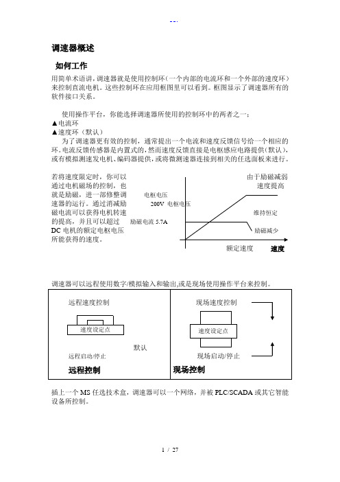
控制操作面板
◎
JOG
现场控制键
电源打开时,标准信息就显示在上面。很快被默认显的示产品描述和产品代码—(如 上图所示)的“欢迎屏幕所取代。这一屏幕在菜单系统的上部。
调速器可以用下面操作模式:
远程控制模式: 允许对应用程序的进行完全访问; 现场操作模式:提供驱动器的本地控制和监控。
这块电源板(印有上面的)能被改变作为内部电机励磁电源或外部 的电机励磁应电源。
5 / 27
内部的电机励磁(此板的默认值)
当三相电源连接到 L1/L2/L3 时,电机励磁输出端子 D3 和 D4 被激发。内部电机励磁 被使用。端子 D1 和 D2 没有被激发。 内部电机励磁电源装有 10A 熔断器,FS2&FS3。
DC1500操作手册

DC1500操作手册安放位置应放在干燥、前后通风的位置,尽量避免烟尘,以防止过热。
三相输入接线将三相线机器右侧板拆下,将三相线接到交流接触器的输入端L1、L2、L3,将地线接到标有标志的螺栓上,机器通常按440V AC出厂,在国内应按380V AC一. 输出接线a)输出接线柱:前面板上标有“Positive(+)”“Negative(-)”,以接工作电缆和地线,当直流正接时,接工件电缆(地线)“Positive(+)”,直流反接时,地线接“Negative(-)”。
b)辅助电源:机器控制输出端31、32号线间有115V AC电压,功率1KW。
c)接送丝机:国内一般用于接NA-3、NA-5送丝机,将前面板上的控制端盖板打开,按接线图接线。
d)接碳弧气刨:将送丝机连线拆掉,将控制端2、4号线短路。
e)DC1500并联:订T14273备件,按图将二台DC1500并联,可输出3000A/100%二. 操作●暂裁率:DC1500为1500A/60V/100%●设置极性:按照工艺要求将工作电缆和地线接到相应的接线柱、控制面板上的“Electrode Negative-Electrode Positive”(焊丝接负-焊丝接正极,开关应与焊丝实际连接的极性相匹配。
●焊机启动:按“on-off”开关启动或关闭焊机,当焊机启动时控制面板中间的红灯要亮。
●近控/遥控:当从送丝机控制箱上控制焊机的输出时要将开关拔到“Remote”(遥控),当用焊机上的旋钮调节;焊机输出时,将开关拔到“output control at DC1500(近控),数字1到10表示输出大小。
●模式开关(Mode Switch):开关有三档CV Innershield(CV自保护),CVSubmerged arc(CV埋弧焊),VV Submerged arc(VV埋弧焊)。
CV Innershield(CV自保护)为平特性输出,输出电压20-60V,用于自保护焊式其他明弧焊。
DC电机变速控制器系列说明书

174311.00 AND M1740007.00DC DRIVE-1Q SCR-CHASSISThe 174311.00 and M1740007.00 series of drives area reliable and cost-effective solution for controllingyour permanent magnet or shunt-wound DC motorsin variable-speed applications. They use SCR’s toprovide full-wave rectifi cation of the AC line input.This dual voltage drive operates using 115 VAC or230 VAC, 50/60 Hz, to operate 90 or 180 VDC SCRbrush-type motors from 1/20 to 2 HP. Packagedin a compact footprint, these user-friendly drivespossess diagnostics and options to accommodateuser needs.FEATURESIndustry Standard Footprint - Traditional mountingpattern and footprint allows for replacing competitivedrives.Field Supply - Voltage output to energize the fi eldwinding of a shunt-wound motor.Stopping Modes - Inhibit (N.O.) for coasting to a stop.Can be used for frequent starting and stopping.Diagnostic LEDs - Current Limi tORDERING INFOSPECIFICATIONS • AC Line Voltage: 115 / 230 VAC, ±10%, 50/60 Hz, 1Ø• Field Voltage with 115 VAC Line (230 VAC Line): 50/100 (100/200) VDC • Maximum Field Amperage: 1 Amp• Acceleration Time Range with 90V Armature: 0.5 - 11 secondswith 180V Armature: 0.5 - 22 seconds • Deceleration Time Range with 90V Armature: coast to 13 seconds with 180V Armature: coast to 25 seconds • Analog Signal Range with 90V Armature: 0 - 1.4 VDC •with 180V Armature: 0 - 2.8 VDC Input• Impedance (S1 to S2): >100K Ω• Form Factor.: 1.37 at base speed• Load Regulation: 1% of base speed or better • Speed Range: 60:1•AmbientTemperature Range: 10°C - 55°CDIMENSIONAL DRAWINGS — INCHES [MILLIMETERS]WIRINGTRIM POTS Acceleration IR Compensation Current LimitMaximum Speed Deceleration Minimum SpeedGROWTH IS MUTUAL.It’s the result of decisions well made, and commitments perfectly executed. When we do things right, your growth is impacted as well. From solutions that save energy and money, to robust systems that keep you up and running, we’ll anticipate your needs and deliver beyond your expectations. See what deep roots, a strong core product line, talented teams and a commitment to excellence can do for you. We invite you to grow with Regal.ACCESSORIES900282.01: Inhibit Plug with 18” wire leads006708.01: Potentiometer kit (included with purchase of drive)174314.00: Heat sinkMOTORFUSE*FUSEPOWER SWITCHAC LINE VOLTAGE 115/230 VAC10K OHM SPEED ADJUST POTENTIOMETERCW* NOTE: Do not add fuse to L2unless input voltage is 230 VAC.NOTE: DO NOT make any connections to F1 and F2 if using a permanent magnet motor .INHIBIT SWITCH CLOSE TO STOPRegal and Leeson are trademarks of Regal Beloit Corporation or one of its affiliated companies.©2018 Regal Beloit Corporation, All Rights Reserved. MCSSP18041E • Form# L0042EAPPLICATION CONSIDERATIONSThe proper selection and application of power transmission products and components, including the related area of product safety, is the responsibility of the customer. Operating and performance requirements and potential associated issues will vary appreciably depending upon the use and application of such products and components. T he scope of the technical and application information included in this publication is necessarily limited. Unusual operating environments and conditions, lubrication requirements, loading supports, and other factors can materially affect the application and operating results of the products and components and the cus-tomer should carefully review its requirements. Any technical advice or review furnished by Regal Beloit America, Inc. and/or its affil-iates (“Regal”) with respect to the use of products and components is given in good faith and without charge, and Regal assumes no obligation or liability for the advice given, or results obtained, all such advice and review being given and accepted at customer’s risk.For a copy of our Standard T erms and Conditions of Sale, please visit (please see link at bottom of page to “Standard T erms and Conditions of Sale”). T hese terms and conditions of sale, disclaimers and limitations of liability apply to any person who may buy, acquire or use a Regal product referred to herein, including any person who buys from a licensed distributor of these branded products.Regal Beloit America, Inc.1051 Cheyenne Avenue Grafton, WI 53024Customer Service: 262-377-8810Fax: 262-377-9025。
HDC1500DX精简版:操作使用各功能

HDC1500辅助菜单辅助菜单当按钮Sequence, Setup同时按下,显示辅助菜单。
当处于辅助菜单时,按钮Sequence和按钮Setup的 LED闪光。
通过按Sequence按钮向前滚动,或按Setup按钮向后滚动。
在任何时间离开辅助菜单时,请同时按下Sequence, Setup。
1 代码离开辅助菜单时,会被询问是否有一个口令代码,这是通过在顶端显示器上出现的“CODE”来指示的。
在下端的显示器上指示默认值代码“OFF”是关闭的。
可通过转动调节Adjust来设定一个从0到999的数字口令。
当重新进入辅助菜单时,口令代码必须被正确输入才能进入辅助菜单。
错误的输入次数被记录,五次输入口令错误后将被锁定,在下端的显示器上指示“LOCK”。
5次失败尝试后,电源可能会继续焊接,但是辅助菜单不可用。
同时按下Program,Sequence, Setup,Upper display四个按钮重新设置口令,当口令需要被重新设置时,“CODE”会显示在上端显示器上,并且“RESET”会显示在下端显示器上。
再同时按下Program,Sequence, Setup,Upper display 四个按钮,将恢复到出厂默认值。
这是通过上端显示器出现的“WIPE”来指示的。
重新设置也将关闭掉口令代码的原有状态。
2 电源选择上端显示器显示“PPS”。
下端显示器显示“ON”或“OFF”。
使用Adjust 调节选择“ON”或“OFF”。
3 电压范围锁当“LOCK”被显示在下端的显示器上时,电压范围锁被激活,并且V的LED点亮。
通过默认值,电压范围锁被关闭,通过上端的显示器上的“OFF”来证实。
从预置电压中可以设置一个在0-10V之间的电压变化,按下Upper display按钮并旋转Adjust按钮到需要的电压。
电压范围锁是一个相关程序,针对每个程序一个不同的电压变化可能被锁住,并且与送丝速度和电流无关。
如果锁被运用,只有那些与锁相关的程序是可进入的。
直流调速装置调试参数说明
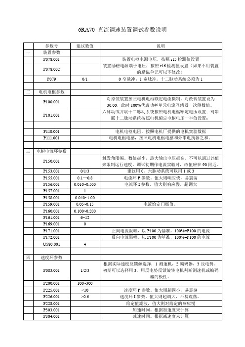
6RA70 直流调速装置调试参数说明
1、必须先检查硬件接线,确认正确。
特别是串联或并联的电枢极性。
2、第一次送电应该保证电枢回路为开路状态,快开为分断状态,不能直接接到电动机。
3、上电正常后应先做小电流电压试验:根据装置的输出电压在直流回路侧接若干个串联在一起的灯泡,
修改电流环输入P601.001=0401,限制P150.001>90,修改P401.001数值使稍大于P159+0.05,监视r018数值,启动、使能,观察r018的变化情况,该数值应向小变化,并最终达到P150定义的限幅值并稳定。
若正常,则调整P150数值减小,观察电枢电压表的变化情况。
随着P150数值的减小,电枢电压逐渐增加。
正常后可将P401的数值改为相反方向,按照上面的步骤观察另一组的工作情况,并做好记录。
在相同电枢输入电压下,对正反组桥来说,触发角相同,输出的直流电压是一致的。
同时记录好电枢电压的极性。
4、然后作电流实验:建议快开主触点为分断状态,用总截面积不大于20mm2的导线短接快开主触点。
P150限制住触发角,建议不小于85,限制电枢电流P171、P172。
按照上面步骤由P401输入电流给定,依次按比例增加,记录r18、r19、r20数值,观察给定电流与反馈电流及触发角的关系,以导线承载电流为限。
在相同的给定下,正反组整流桥触发角应一致,实际电流应一致。
1500V直流开关柜实操手册041226(可编辑修改word版)

1500kV 直流开关柜深圳地铁一期工程牵引降压混合变电所直流开关柜设备是由上海成套厂生产, 本直流开关为空气绝缘、金属封闭户内式。
柜体为轻型自攻螺钉紧固、镀锌钢板框架的坚固自承结构。
其底部及顶部开放保障了空气流通,可释放直流快速断路器工作时喷发的热气体。
开关柜前、后、侧面的防护等级为IP20。
一、参数二、结构深圳地铁一期工程牵引降压混合变电所直流开关柜一般主要由2 台进线柜、4 台馈线柜、1 台负极柜及1 台联跳柜组成。
(车辆段及会展中心变电所除外)三、功能直流开关柜主要用于DC1500V 的电能分配,通过正线柜及馈线柜给接触网供电,再通过列车回流到负极柜,最后回到负极。
直流开关柜可通过开关对接触网的供电进行控制,合理分配电能。
直流开关柜具有测量电压及电流功能,同时配置了几种直流保护,具体如下:1.继电保护装置配置1.11500V 直流馈线断路器本体内设大电流脱扣保护Imax(深圳地铁整定10000A)。
1.21500V 直流馈线开关柜内设DCP-106 微机型综合性保护装置。
1.3牵引变电所负极柜内设一套框架保护(由DCP116 实现)。
1.4向接触网同一供电区间供电的两馈线断路器设双边联跳装置,车辆段不设双边联跳。
2.DCP-106 保护功能配置2.1电流速断保护IOP2.2过电流保护OCP2.3热过负荷保护TIP2.4∆I 电流增量+di/dt 电流变化率保护ROR2.5带线路测试的合闸及自动重合闸LT3.DCP-106 保护符号说明3.1电流速断保护IOP 符号定义:+I>>电流速断整定值、-I>>逆向电流整定值、t>>电流速断整定时间。
3.2过电流保护OCP 符号定义:+I>过电流整定值、t>过电流时间整定值。
3.3接触网热保护符号定义:K-wam 接触网过热报警参数、K-trip 接触网过热跳闸参数、K-reset 接触网热继电器复归参数、K-spl 接触导线电流分劈系数、I-tn 允许的持续电流值、T- th 时间乘数。
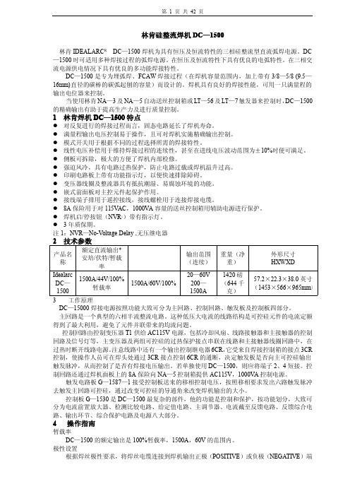
林肯DC-1500直流电焊机大修经验总结

林肯DC-1500直流电焊机大修经验总结
高宝明;黄雄飞;李国锋;金江
【期刊名称】《焊管》
【年(卷),期】2005(028)006
【摘要】叙述了美国林肯DC-1500直流电焊机变压器一次线圈严重烧坏后的检查、测试、修理及试验方法.寻求较经济的大修方案,努力使修理后的电焊机达到原有技术性能,以满足钢管生产工艺需要.
【总页数】4页(P52-55)
【作者】高宝明;黄雄飞;李国锋;金江
【作者单位】中石化江汉石油管理局沙市钢管厂,湖北,荆州,434001;中石化江汉石油管理局沙市钢管厂,湖北,荆州,434001;中石化江汉石油管理局沙市钢管厂,湖北,荆州,434001;中石化江汉石油管理局沙市钢管厂,湖北,荆州,434001
【正文语种】中文
【中图分类】TG434.1
【相关文献】
1.林肯电气公司胡总一行到访成都电焊机研究所 [J],
2.山区高速公路大修工程成功经验总结 [J], 胡亮
3.林肯城市发动机大修后不能起动 [J], 刘彰武
4.林肯DC-1500型自动埋弧焊机故障排除 [J], 付辉
5.4000KW高压同步电动机大修经验总结 [J], 吴丽华
因版权原因,仅展示原文概要,查看原文内容请购买。
直流调速器BC2000TA说明书
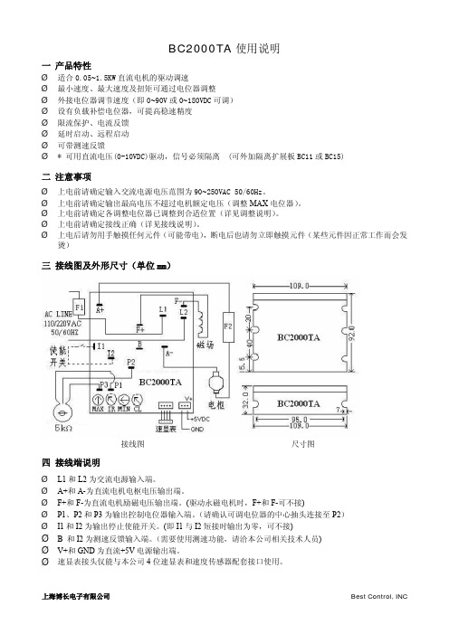
BC2000TA使用说明一 产品特性Ø适合0.05~1.5K W直流电机的驱动调速Ø最小速度、最大速度及扭矩可通过电位器调整Ø外接电位器调节速度(即0~90V或0~180V D C可调)Ø设有负载补偿电位器,可提高稳速精度Ø限流保护、电流反馈Ø延时启动、远程启动Ø可带测速反馈Ø*可用直流电压(0-10V D C)驱动,信号必须隔离 (可外加隔离扩展板B C11或B C15)二 注意事项Ø上电前请确定输入交流电源电压范围为90~250V A C50/60H z。
Ø上电前请确定输出最高电压不超过电机额定电压(调整MAX电位器)。
Ø上电前请确定各调整电位器已调整到合适位置(详见调整说明)。
Ø上电前请确定接线正确(详见接线说明)。
Ø上电后请勿用手触摸任何元件(可能带电),断电后也请勿立即触摸元件(某些元件因正常工作而会发烫)三 接线图及外形尺寸(单位m m)接线图尺寸图四 接线端说明ØL1和L2为交流电源输入端。
ØA+和A-为直流电机电枢电压输出端。
ØF+和F-为直流电机励磁电压输出端。
(驱动永磁电机时,F+和F-可不接)ØP1、P2和P3为输出控制电位器输入端。
(请确认可调电位器的中心抽头连接至P2)ØI1和I2为输出停止使能开关。
(即I1与I2短接时输出为零,可不接)Ø B 和I2为测速反馈输入端。
(需要使用测速功能,请洽本公司相关技术人员)ØV+和GND为直流+5V电源输出端。
Ø速显表接头仅能与本公司4位速显表和速度传感器配套接口使用。
五 电气参数不额外加散热片外加足够大面积散热片输入电压(VAC ) 50/60Hz电机电压 (VDC )最大直流输出电流 (Amps ) 最大输出功率KW (HP )最大直流输出电流 (Amps ) 最大输出功率KW (HP )90--130 0--90 0.375 (0.5) 0.75 (1) 185--2500--1806.00.75 (1)12.01.5 (2)六 电气性能调速比 50:1 限流范围 0-150% 负载调整率 1% 加速时间 0.5-4.0s最低转速调整范围 0-30%最高转速调整范围 50-110% 线电压调整率 0.5% 控制线性度2% 测速反馈电压 (可选) 0-5 V/krpm 最大瞬间启动电流 电流设定值的3倍最高环境温度 (满载) 45℃七 调整说明(**所有调整电位器在逆时针旋转到底时为最小值**) 1. 最高转速调整 (MAX)当要求电机的最高转速为某一特定转速时,调整该电位器便最高转速符合控制要求。
(整理)调速器说明书

WZTS—1型可编程微机调速器说明书目录A 总体概论一、概述 (4)二、主要功能 (4)三、主要参数和技术性能 (5)四、主要特点 (6)B 电气部分一、概述 (6)1 整机的主要性能 (6)2 电气部分主要技术性能 (7)3 结构形式 (7)4 调速器电气部分主要特点 (7)二、电气部分硬件构成 (8)1 电气部分系统配置 (8)2 PLC主机模块CPU 224XP CN (9)3触摸式字符型操作终端E-view MD204L (9)4集成智能可控整流模块MJYS-QKZL-30 (9)三、简单原理 (10)1 调速器的调节特性 (11)2 开机特性 (12)3 停机特性 (13)四、人机界面(智能显示单元) (14)1 触摸式字符型显示操作终端 (14)2 指示灯显示 (16)3 开关按钮操作 (16)五、运行操作 (17)1 微机调速器的运行状态 (17)2 电气部分操作介绍 (18)六、电气部分维护及故障处理 (18)1 一般维护 (18)2 故障类型与处理 (19)C 相关图纸1、直流电动机控制回路接线2、WZTS—1型调速器屏后接线及端子图3、WZTS—1型调速器机箱内部接线图A 总体概论一、概述:WZTS—1型微机调速器是适用于高校模拟实验电厂发电机组数字监控平台的配套装置。
主要部件均采用知名厂家产品,技术成熟、可靠。
调速器具有较为完备的功能,技术先进,抗干扰能力强,可靠性较高,完全满足高校模拟实验电厂发电机组对调速器的各项技术要求。
此外,该微机调速器采用高性能可编程控制器——德国西门子公司的S7-200系列PLC作为硬件主体,平均无故障时间MTBF≥50000小时,装置可靠性高;以触摸式字符型带背光源操作终端作为人机界面,现场操作简便;采用先进的集成静止变流模块,实现了微机调速器的全数字式控制;具有485总线接口,可实现远方监控功能。
二、主要功能1、自动调节与控制功能:◆转速调节:在同步发电机空载运行时,可实现机组转速的调整,与自动准同期装置配合,能实现快速并网。
直流调速器简单参数设置

直流调速器简单参数设置装置调试大纲6RA70 直流装置简要调试步骤一. 送电前检查装置和电机1、辅助电源系统送电检查2、接地线和辅助电源零线检查3、电机绝缘检查和编码器安装检查4、电机电枢绕组和励磁绕组对地绝缘和电阻检查5、检查装置风机和柜顶风机电源和转向6、检查电机风机电源和转向7、装置电源和控制电源检查8、编码器电源和信号线检查二. 基本参数设定(计算机或PMU 单元完成)1、系统回复出厂设置:合上装置控制电源和操作控制电源,用PMU 执行功能P051= 212、负载周期参数设定:P067=1-5 选择负载过负荷周期,见手册,通常默认也可3、进线电压设定P078.01= 630V 主回路进线交流电压,作为判断电压故障的基准值P078.02= 380V,励磁进线电压作为欠压或过压的判断门槛电压,相关参数见P351,P352,P361-P364.(根据实际情况)。
4、电机基本参数参数设定:P100(F)= 额定电动机电枢电流(A)P101(F)=额定电动机电枢电压(V)P102(F)= 额定电动机励磁电流(A)P103(F)=最小电机励磁电流(A),必须小于P102 的50%.在弱磁调速场合,一般设定到防止失磁的数值(根据实际情况)5、实际速度检测参数设定P083(F)=实际速度反馈选择当P083=2 (脉冲编码器) 时,100%速度为P143 参数值P083=3 (EMF反馈) 时,100%速度为P115 参数值所对应的速度P140=0 或1,脉冲编码器类型选择。
电枢反馈P083=3 时,令其为零;编码器反馈时P083=2,令其为“1”。
P141=1024 ,脉冲编码器每转脉冲数P142=1,编码器15V 电源供电P143(F)= 编码器反馈时最高的运行速度(转/分钟)P148(F)=1,使能编码器监视有效(F048 故障有效)6 、励磁功能参数设定P081=0 恒磁运行方式 (弱磁优化前设置值)P081=1 弱磁运行方式(进行弱磁优化时设置,优化后设置为1)P082=2 励磁运行模式,达到运行状态>07 后,经过P258 的延时,输出经济励磁电流P257. P257(F)= 0 (%P102) 停机励磁(详见参数表)7 、斜坡函数发生器相关参数设定(可以在优化后设定)P303.01(F)= 10 S(加速时间),根据实际情况P304.01(F)= 10S(减速时间),根据实际情况P305.01(F)= 0.5S(上升圆弧时间),根据实际情况P306.01(F) = 0.5S(下降圆弧时间),根据实际情况三. 检查主电机励磁令P082=2,合励磁进线电源,改变P257=5%,30%,50%,100%,观察励磁表指示情况。
直流调速装置调试参数说明
6RA70 直流调速装置调试参数说明
1、必须先检查硬件接线,确认正确。
特别是串联或并联的电枢极性。
2、第一次送电应该保证电枢回路为开路状态,快开为分断状态,不能直接接到电动机。
3、上电正常后应先做小电流电压试验:根据装置的输出电压在直流回路侧接若干个串联在一起的灯泡,
修改电流环输入P601.001=0401,限制P150.001>90,修改P401.001数值使稍大于P159+0.05,监视r018数值,启动、使能,观察r018的变化情况,该数值应向小变化,并最终达到P150定义的限幅值并稳定。
若正常,则调整P150数值减小,观察电枢电压表的变化情况。
随着P150数值的减小,电枢电压逐渐增加。
正常后可将P401的数值改为相反方向,按照上面的步骤观察另一组的工作情况,并做好记录。
在相同电枢输入电压下,对正反组桥来说,触发角相同,输出的直流电压是一致的。
同时记录好电枢电压的极性。
4、然后作电流实验:建议快开主触点为分断状态,用总截面积不大于20mm2的导线短接快开主触点。
P150限制住触发角,建议不小于85,限制电枢电流P171、P172。
按照上面步骤由P401输入电流给定,依次按比例增加,记录r18、r19、r20数值,观察给定电流与反馈电流及触发角的关系,以导线承载电流为限。
在相同的给定下,正反组整流桥触发角应一致,实际电流应一致。
直流电机调速器使用说明书

直流电机调速器使用说明书名称:直流电机调速器,型号:DM103AH一、功能特点1、本PWM直流电机调速器(型号DM103AH) 主要用来驱动直流有刷电机,专为运动控制卡如MACH3,USBCNC或PLC等控制直流电机而设计的,具有调速,开/停,正反转,堵转报警输出,过流保护,短路保护。
状态指示等功能。
2、调速器可以与各种运动控制卡,PLC等实现联合控制。
也可以独立控制电机。
通过设置调速器,可以匹配电压20-110V,功率2000W以内的各种不同型号的直流有刷电机。
可以单独通过外接开关与旋钮来用;也可以配PLC,运动控制卡、工控机等来用。
3、功能接口齐全。
可以外接0-5V,0-10V,4-20MA,PWM等信号及外接电位器手动共5种控制方式来调速。
4、有开停与正反转接口,有保护输出接口。
5、支持交流或直流输入,不存在接反电源烧东西的问题。
供电范围宽AC15-110V(50/60HZ),DC+20-+150V,6、有电源指示灯,绿灯是电源指示灯,红灯亮是报警指示灯。
6、本驱动器也可以用来驱动锅炉发热丝,震动盘,电磁机等负载。
负载适用与2KW以内的非容性的所有负载。
二、调速器接线端口定义:1、高压接口:M-:接直流有刷电机负极。
极限负载2KW,标称负载1.5KW,电机方向不对,交换电机两条线即可。
M+:接直流有刷电机正极。
极限负载2KW,标称负载1.5KWNC:空脚不用接,安全间距用。
ACIN:交流电源输入接口,也可以接直流,输入不分正负电源输入范围:AC15-110V 50/60HZ,DC20-150VNC::空脚不用接,安全间距用。
ACIN::交流电源输入接口,也可以接直流,输入不分正负,电源输入范围:AC15-110V 50/60HZ,DC+20-+150V2、模拟量输入接口:5V:电源5V输出脚。
外接电位器调速时的电位器接线脚。
外接正反转控制按键脚。
5V的端口在接电位器调速和接开关正反转或开停时会接线。
大功率有刷直流电机调速器说明书

大功率有刷直流电机调速器【特点】1、交直流电源通用2、PWM脉宽调制调速3、适应多种不同电压的直流电机最高可调400V直流电机4、过载短路保护5、有软启动功能启动时对电源无充击6、强大的适用性集成手动调速,模拟电压调速,维宏卡控制调速,Mach控制调速,PLC输出PWM控制调速。
7、正反转调节功能8、急停控制9、人性化端子外接设计10、可扩展风扇强制散热接线示意图【功能及使用说明】电源电压:本PWM直流电机调速电路器采用交直流电源供电,电源电压在12V一400VDC 之间都可以正常工作,用户可以直接采用变压器或者开关电源提供。
但注意电机额定电压超过30V时,要采用双路电源输入(其中一路为电路供电,一路为电机供电)。
采用输出电流较低的开关电源时,可能会因为电机电流过大而导致开关电源自保护。
接入电机供电,一般要高于电机额定电压的1.5倍,像12V的直流电机为。
具体使用方法:1、当用户需要为额定电压为单路电源输入,如下图所示,只需把电机供电与电路供电并联一起。
2、当用户需要为额定电压为)的直流电机进行调速时,需要双路电源输入,如上图所示,需在“电机电源输入”端子处输入一组符合电机功率要求的电源,为电机供电;另外需要在“控制板电源输入”端子处输入一组12-30V(1A 以上)的直流电源。
3、调速的使用:本调速器有手动模式和自动模,手动模式利用电位器手动调节输入电压从5V到0V,转速从0到最大无级调速。
若停止状态下收到维宏卡或电脑并口信号自动转为自动模式,这时手动模式失效,自动模式下当控制信号关闭后自动停止,紧急情况下可用急停开关停止。
4、急停开关的使用:如接线图所示,急停按钮应为自锁按钮,接常开,当急停按钮按下也就是导通后,电机处于急停状态,(当不使用电机时,请按下急停开关,以预防误操作)急停开关接口已带光耦,可通过电脑并口输出控制。
Mach3设置与电脑并口连接参考,请根据自己的实际情况作调整1、设置主轴输出端口2、设置使能输出端口3、设置主轴为脉宽调制控制并设脉宽调制基数为1004、并口连接示意图主轴调试:1-点开手动编程界面3-输入M05 主轴停转5-M05主轴停转Mach3控制主轴客户注意:调速器完全兼容Mach3,由于各式各样的接口板接线不一样,为保证能正常使用Mach3调速请购买适合的接口板,非本店接口板不提供连接Mach3技术支持(各商家有自己设计方案请谅解),如配合其他接口板出现不能正常使用Mach3调速或损坏调速器后果自负。
DC-1500~1200焊机操作手册
第 2 页 共 42 页
子上,连接工件电缆到另一端子上。
使主焊机上的“焊丝正极—焊丝负极”两位开关的设置与焊丝电缆的连接极性相一致。该开
关的设置对林肯送丝操作相对主焊机的正常控制是非常必要的。
启动焊机
按下“启动”(START)和“停止”(STOP)按钮时,进行启动或停止焊机工作。当焊机进
行工作时,位于控制面板中间的红色指示灯发亮。
c. 对冷起动而言,使用的一种工件是干净的和焊丝与电极板相连;
d. 对热起动而言,当电线连接到工作状态以前,移动应该开始;
e. 设置 NA-3 开路电压大概范围,对最初的试验状态,选择的电压设置在下面表的最低的状
态,逐渐地设置控制到 2。
这是一个大概的设置,应该注意到使用 DC-1500,OCV 要求一个理想的起动比别的理想电
对本设备上进行工作前,在保险盒或开关处关闭输入电源。
请勿接触设备带电部位。
注:查找“触发板”和“控制/故障保护电路板”的 P.C.板时,打开焊机左侧上部机箱面板,印刷
第 3 页 共 42 页
电路板上有名牌标注。 1.正常的维护 a. 风扇的马达是封闭的。 b. 在极其灰尘多的情况下,灰尘附着在空气流通道内,将使焊机发热,定期地用低压风吹掉灰
制回路还通过焊机面板上的 8A 保险向 NA—5 控制箱提供 AC115V,1000VA 控制电源。
触发电路板 G—1587—1 接受控制板送来的移相控制电压,按照移相要求发出六路触发脉冲
去触发主回路可控硅,通过改变可控硅的导通角来改变焊机输出的大小。
控制板 G—1530 是 DC—1500 最复杂的部件,他的功能是控制和保护,按功能划分,大致可
变压器线圈及整流器具有抵抗潮湿、易腐蚀环境的功能。
TS1DH系列直流电动机调速器用户手册
TS1DH 系列直流电动机调速器
前言
感谢您使用英杰电气公司生产的 TS1DH 系列直流电动机调速器。 TS1DH 系列直流电动机调速器,是在原 TS1D 产品基础上的升级,本调速器设计紧凑,功能完善; 采用一体化结构,体积小,重量轻,使用维护方便。 TS1DH 系列直流电动机调速器,具有如下特点: z 采用单相半控桥结构,双闭环控制,电流环为内环,电压环(或速度环)为外环; z 输入采用线性光电耦合器隔离;给定部分、调节部分、晶闸管主回路三者间电气隔离,抗干
1
1 安全及注意事项
“危险”与“注意”的定义:
TS1DH 系列直流电动机调速器
由于没有按要求操作,可能造成设备严重损坏或人员伤亡的场合。
1.1 安装 ......................................................................................................................................2 1.2 配线 ......................................................................................................................................2 1.3 维护 ......................................................................................................................................2 2 产品信息 .........................................................................................................................................3 2.1 型号定义 ...............................................................................................................................3 2.2 铭牌 ......................................................................................................................................3 2.3 产品系列 ...............................................................................................................................3 2.4 技术参数 ...............................................................................................................................4 2.5 外形及安装尺寸 ....................................................................................................................5 2.6 应用标准 ...............................................................................................................................6 2.7 认证 ......................................................................................................................................6 2.8 缩略语...................................................................................................................................6 3 安装配线 .........................................................................................................................................7 3.1 开箱检查 ...............................................................................................................................7 3.2 使用环境 ...............................................................................................................................7 3.3 安装 ......................................................................................................................................7 3.4 电气配线 ...............................................................................................................................8 3.5 连接框图 ...............................................................................................................................8 3.6 端子说明及调整开关 .............................................................................................................8 3.7 应用举例 ........................................................................................................9 4 功能介绍 .......................................................................................................................................13 5 通电及运行....................................................................................................................................18 5.1 指示灯.................................................................................................................................18 5.2 电位器.................................................................................................................................18 5.3 轻载试验 .............................................................................................................................18 5.4 额定负载使用 ......................................................................................................................20 6 故障处理及保养维护 .....................................................................................................................21 6.1 故障处理 .............................................................................................................................21 6.2 保养维护 .............................................................................................................................22 附录: 保修单 保修协议 质量反馈单
- 1、下载文档前请自行甄别文档内容的完整性,平台不提供额外的编辑、内容补充、找答案等附加服务。
- 2、"仅部分预览"的文档,不可在线预览部分如存在完整性等问题,可反馈申请退款(可完整预览的文档不适用该条件!)。
- 3、如文档侵犯您的权益,请联系客服反馈,我们会尽快为您处理(人工客服工作时间:9:00-18:30)。
DC-1500直流电机调速器
使用手册
誉冠电子科技有限公司
在使用本产品前 请您详细阅读本使用说明书。
由于不遵守该使用及安装说明书中规定的注意事项,所引起的任何故障和损失均不在厂家的保修范围内,厂家将不承担任何相关责任。
请妥善保管好文件,如有相关疑问,请与厂家联系。
安全注意事项
·请专业技术人员进行安装、连接、调试该设备。
·在带电情况下不能安装、移除或更换设备线路。
·请务必在本产品的电源输入端与电源(电瓶)之间加装必要的保护装置,以免造成危险事故或致命伤害;需要加装:过流保护器、保险、紧急开关。
·请做好本产品与大地、设备之间的隔离及绝缘保护。
·如确实需要带电调试本产品, 请选用绝缘良好的非金属专用螺丝刀或专用调试工具。
·本产品需要安装在通风条件良好的环境中。
·本产品不能直接应用在高湿、粉尘、腐蚀性气体、强烈震动的非正常环境下。
该标志表示一种重要提示或是警告。
概 述:
DC-1500小功率直流电机调速器,它具有体积小,安装方便、调速精度高、价格低、功能齐全等优点。
广泛使用于电线、电缆、轻工、纺织、造纸、化工、印染、冶金、橡塑、拉丝、挤出机械、医疗器械、食品生产、印刷包装等各种行业,与永磁直流电机配套使用。
对小型直流电机电枢供电,使直流电机实现恒转矩无级调速。
本装置主电路采用集成电路,并带有电压负反馈,电流截止反馈电路及软启动等环节,提高调速精度,限制启动电流,控制电路采用集成电路触发双向可控硅,电路线路简单,工作稳定可靠。
可外接控制包括:位移控制器、NPN 光电开关、PNP光电开关、电脑或变频器等模拟输出DC0~10V无级控制。
一、产品特点:
■采用SMT技术 体积小
■闭环P I调节
■电流设置和限流保护
■软启动功能
■标准信号输入0 - 5V 或 0-10V、4.7K 电位器
■跟随性好.响应速度快
■调速比宽 机械特性硬
二、电气参数:
□输入电压AC: 110V / 220V±10﹪
□频 率: 50/60HZ
□输出电压DC: 0-(110V-220V)(可以设置)
□速度信号: 0-5V/0-10V/电位器
□最大连续电流: 7A
□调 速 比: 1:20
□外形尺寸: 113 *85 * 45 mm
三、产品性能:
1、具有较硬的机械特性
2、具有较宽的调速范围,(0—最大)。
3、具有较快的动态响应过程。
4、具有加、减速时自动平滑的过渡过程。
5、可靠性高,结构紧凑,具有极高的性价比
四、调速器接线端子/功能示意图:见图2
图2
五、电位器调整说明:
1、输出电压调节
顺时针调整输出电压升高,反之电压降低。
2、截止电流调节
顺时针调整截止电流增大,反之变小。
截止电流应根据负载大小调整。
六、控制信号输入方式的选择:
1、用电位器调速不用光电开关和模拟输入信号时的连接方式:见图3,需用
导线短接第8和第10端子
图3
2、用电位器调速及用NPN光电开关时的连接方式:见图4
图4
3、用电位器调速及用PNP光电开关时的连接方式:见图5、图6
图5
图6
4、使用电脑或变频器等模拟输出DC0~10V无级控制:见图7、图8
图7
图8
七、常见故障解答:
警告
通电状态下调速器内存在危险电压,在处理故障时需要断开电源。
调速器内部存在高
压可能会成严重或致命的伤害
处理故障前请遵照以下步骤检查:
1、断开调速器上的电源。
2、确认所有的外部连接是否正确 。
3、检查PCB电路板上有无异物或其他导电介质。
4、确认外部没有短路或是与地线相连。
5、检查调速器的额定电枢电压和电流与电机的额定值匹配。
淘宝店铺: 誉冠电子科技有限公司
故障
造成原因
解决方法
断保险丝 1、保险丝规格是否合适。
2、输出是否短路。
3、马达与驱动器是否匹配。
1、根据马达的功率.选择合适的保险丝。
2、检查驱动器与马达间的连线。
3、选择规格合适的驱动器。
马达不运转
1、给定信号
2、线路问题.
3、负载过大,进入保护状态
1、调整速度电位器.
2、检查驱动器和马达间的连线.
3、检查负载是否过大,调整驱动器的过载电流设置
马达速度太快 输出电压过高
逆时针调整输出电压调整电阻,使输出电压符合负载要求.
马达速度降低 输出电压过高.
顺时针调整输出电压调整电阻,使输出电压符合负载要求.
马达反方向运转 〔0UT 〕+ —端子.接线颠倒
对调 0UT 〕+ — 端子.。