KL16-pin 列表分配
ssd1306双色中文
Ver:A
修正完成 20130326 20130522
i
金晨电子
Ver:A
内容
修正历史................................................................................................................................i 内容..................................................................................................................................... ii~iii 11.. 基本功能...............................................................................................................1~6
金晨电子
刘玉汉化,本人不会英文,以下翻译主要有谷歌翻译提供
金晨电子
产品名称: 产品ID:
OEL 显示模块
顾客:
批准
来自: 金晨电子
批准
金晨电子
修正历史
零件号码 UG-2864TMBEG01
修正 A B
内容
New
R 变更为 R IRE)参数 0XCF 变更为 0X66
1.1 显示规格 ................................................................................................................. 1 1.2 机械规格............................................................................................................ 1 1.3 有效面积 / 内存映射 & 像素结构...................................................................... 1 1.4 机械图纸.................................................................................................................... 2 1.5 引脚定义 ............................................................................................................................. 3 1.6 方框图............................................................................................................................ 5
TEC-XP16实验指导书

计算机组成原理实验指导书王潇编写仲恺农业工程学院计算机科学与工程学院二00八年十月目录第一章TEC-XP16实验计算机系统原理 (1)§1.1TEC-XP16计算机组成原理实验系统概述 (1)§1.2TEC-XP16机指令系统 (8)§1.3TEC-XP16机运算器部件 (12)§1.4TEC-XP16机内存储器部件 (15)§1.5TEC-XP16机的控制器部件 (18)§1.6TEC-XP16机的输入输出及中断 (22)第二章TEC-XP16实验计算机系统实验内容 (24)实验一基础汇编语言程序设计 (24)实验二脱机运算器实验 (29)实验三存储器部件教学实验 (32)实验四组合逻辑控制器部件教学实验 (37)实验五微程序控制器部件教学实验 (51)实验六输入/输出接口扩展实验 (59)实验七中断实验 (63)实验八8位模型机的设计与实现(综合实验) (71)附录 (74)附录1 联机通讯指南 (74)附录2TEC-XP16计算机组成原理实验系统简明操作卡 (77)附录3微程序入口地址映射表 (78)附录4指令流程框图 (80)附录5指令流程表 (82)附录6书写实验报告的一般格式 (86)参考文献 (87)第一章TEC-XP16实验计算机系统原理§1.1 TEC-XP16计算机组成原理实验系统概述一、教学计算机系统的实现方案和硬软件资源概述TEC-XP是由清华大学计算机系和清华大学科教仪器厂联合研制的适用于计算机组成原理课程的实验系统,主要用于计算机组成原理和数字电路等的硬件教学实验,同时还支持监控程序、汇编语言程序设计、BASIC高级语言程序设计等软件方面的教学实验。
它的功能设计和实现技术,都紧紧地围绕着对课程教学内容的覆盖程度和所能完成的教学实验项目的质量与水平来进行安排。
其突出特点是硬、软件基本配置比较完整,能覆盖相关课程主要教学内容,支持的教学实验项目多且水平高。
光纤光学练习题
从“1”耦合到“2”的光功率为sin2(kL)=(1-cos(2kL))/2=1/4
所以cos(2kL)=1/2,所以,2kL=pi/3+2kpi,k=0,+1,-1
最小耦合长度L=pi/(3.2k)=0.052cm
2)x型耦合器有对称型,从output1进入,耦合到input2的为sin2(kL)为1/4,进入input1的有3/4,所以input2输出为1/4mw,input1为3/4mw。
4、光纤中的基模能否被截止,为什么?
答:不能。因为光纤半径不可能为0,入射波长也不可能为无穷大。
四、计算题(要求写出主要计算步骤及结果。共32分)
1、某抛物线分布光纤,n1=1.5,Δ=0.001,纤芯直径2a=50μm,当用波长λ0=0.85μm的光激励时,试求:(共10分)
(1)包层折射率n2=?
D、NA越大,多模光纤的模式色散越小。
10下列光纤的色散,由小到大的排列次序为:
A、多模的GIOF、多模SIOF、单模光纤;B、多模SIOF、多模的GIOF、单模光纤;
C、单模光纤、多模的GIOF、多模SIOF;D、多模SIOF、单模光纤、多模的GIOF
11以下那一种是非零色散位移光纤:
A、G.655光纤;B、G.653光纤;C、G.652光纤;D、G.651光纤。
(1)问此光纤故障点距始端距离有多长?
(2)该OTDR判断故障点的误差为多少?
(3)若OTDR能测的损耗范围为32dB,想用它测试78 km的光缆线路,光缆的衰减系数为0.3 dB/km,问OTDR能否看到末端的衰减曲线?
解:1)由L=Ct/(2n)=3*108*3*10-6/(2*1.5)=300m
MOONS ST驱动器的SCL 说明书
上海安浦鸣志自动化设备有限公司
ST 驱动器的 SCL 使用手册
目
ห้องสมุดไป่ตู้
录
简介... .................................................................................5 SCL 是什么? ................................................................................................................................................5 SCL 的详细资料 ............................................................................................................................................5 开始 ....................................................................................7 步骤一:安装软件 ........................................................................................................................................7 步骤二:用 ST Configurator 设置您的 ST 驱动器 .......... ..............................................
第4章 8086CPU引脚功能,系统组成和时序
3.BHE /S7(Bus High Enable/Status)高8位数据总线允许/ 状态复用信号(输出、三态) 在8086系统中: ①在总线周期的T1时钟内,8086在 BHE /S7引脚输出低 电平( BHE = 0)有效信号,表示高8 位数据总线AD8~AD15 上的数据有效;若 BHE = 1,表示当前仅在数据总线 AD0~AD7上传送低8位数据。信号也作为对I/O电路或中断 响应时的片选条件信号。 ②在T2、T3、TW和T4时钟周期, BHE /S7引脚此时输出 状态信息。在8086中,S3、S7状态没有实际定义。 ③ BHE 和AD0信号相配合,可知系统当前的操作类型, 具体规定见表4.2所示。
表4.1 S4、S3的代码组合与当前段寄存器的关系
S4S3
00 01
当前使用的段寄存器
ES段寄存器 SS段寄存器 当存储器寻址时,使用CS寄存器; 当对I/O端操作或中断矢量寻址时,不使用段寄存器。 DS段寄存器
10
11
⑤S5状态指示当前中断允许标志IF 的状态: 如IF = 1,表明当前允许可屏蔽中断请求; 如IF = 0,则禁止可屏蔽中断。 ⑥S6状态为低电平时,表示8086/8088当前正与总线相连。所 以,在T2、T3、TW和T4时钟周期S6总保持低电平。
6.TEST (-Pin23) 测试输入信号(低电平有效) TEST信号与WAIT指令结合起来使用,CPU执行WAIT 指令后,处于等待状态,当 TEST 0 ,系统脱离等待状态, 继续执行被暂停执行的指令。当CPU执行WAIT指令时, CPU每隔 5个时钟周期就对此引脚进行测试。 TEST引脚信号用于多处理器系统中,实现8086/8088 CPU与协处理器间的同步协调之功能。
9.RESET(--Pin21):复位输入信号---高电平有效 RESET信号高电平至少应保持4个时钟周期。随着 RESET变为低电平,CPU就开始执行再启动过程。复位时, CPU内部各寄存器的状态如表4.3所示。
艾迪UPS W6-10KⅡ使用手册
安全注意事项安全注意事项操作安全 1. 在使用本产品前,请仔细阅读“安全注意事项”,以确保正确和安全的使用。
并请妥善保存说明书。
2. 操作时,请注意所有警示标记,并按要求进行操作。
3. 避免在阳光直接照射、雨淋或在潮湿的环境使用本设备。
4. 本设备不能安装在靠近热源区域,或有电暖炉、热炉等类似的设备附近。
5. 放置UPS时,在其四周要留有安全距离,保证通风。
安装时,请参照说明书。
6. 清洁时,请使用干燥的物品进行擦拭。
7. 若遇火警,请正确使用干粉灭火器进行灭火。
若使用液体灭火器会有触电危险。
电气安全 1. 上电前,请确认已正确接地,并检查接线和电池极性的连接正确。
2. 当UPS需要移动或重新接线时,应将交流输入电源断开,并保证UPS完全停机,否则输出端仍可能带电,有触电的危险。
3. 请使用公司指定的附加装置和附件。
4. 为了符合EMC的要求,UPS的输出线长度应在10米以内。
电池安全 1. 电池的寿命随环境温度的升高而缩短。
定期更换电池可保证UPS工作正常,并保证足够的后备时间。
2. 蓄电池维护只能由具备蓄电池专业知识的人员来进行。
3. 蓄电池存在电击危险和短路电流危险。
为避免触电伤人事故,在更换电池时,请遵守下列警告:安全注意事项 A. 不要佩带手表、戒指或类似的金属物体; B. 使用绝缘的工具; C. 穿戴橡胶鞋和手套; D. 不能将金属工具或类似的金属零件放在电池上; E. 在拆电池连接端子前,必须先断开连接在电池上的负载。
4. 请不要将蓄电池暴露于火中,以免引起爆炸,危及人身安全。
5. 非专业人士请勿打开或损毁蓄电池,因为电池中的电解液含有强酸等危险物质,会对皮肤和眼睛造成伤害。
如果不小心接触到电解液,应立即用大量的清水进行清洗,并去医院检查。
6. 请不要将电池正负极短路,会导致电击或着火。
使用保养 1. 使用环境及保存方法对本产品的使用寿命及可靠性有一定影响,请不要在以下工作环境中使用: A. 超出技术指标规定(温度0℃~40℃,相对湿度20%~90%)的高、低温 和潮湿场所; B. 有振动、易受撞的场所; C. 有金属性粉尘、腐蚀性物质、盐份和可燃性气体的场所。
阿卡1660设备板位图

关于设备中各槽位对各种板卡的支持情况的说明阿尔卡特公司Optinex系列产品产品摈弃了传统的ADM分插复用器或M-ADM多分插复用器结构,采用最先进的背板设计,使系统槽道不再分群路和支路,仅在部分设备上有低速和高速端口之分,这使得设备各槽位配置的通用性和灵活性非常高,可以灵活的配置成终端TM,多复用器系统 (Multi-ADM)或直接配置成交叉连接系统使用,可以满足各种网络拓扑结构的要求(线型、环型和网格型)。
下面就合同中各种设备对于各种板卡的支持情况进行说明。
一、1660SM 10G设备槽位分布如上图所示,其中槽位10、11、12、22用于插入电源、控制、公务板;槽位23和40用于插入矩阵板;其余槽位用于各业务板,支持情况如下表所示:业务板卡支持槽位备注光接口板25-26、28-29、34-35、37-38窄光接口板24-39业务板卡支持槽位备注4×STM-4 主板25, 26, 28, 29, 34, 35, 37,384×STM-1光/电单元板24-39千兆以太网业务板24-39增强型以太网板 8x光接口24-39增强型以太网板 8x电接口24-39二、1660SM设备槽位分布如上图所示,其中槽位10、11、12、22用于插入电源、控制、公务板;槽位23和40用于插入矩阵板;其余槽位用于各业务板,支持情况如下表所示:业务板卡支持槽位备注光接口板25-26、28-29、34-35、37-38光接口板25-26、28-29、34-35、37-38STM-4 光端口24-394×STM-1光/电单元板24-3963x2M 工作板24、27、30、32、33、36、39增强型以太网板 8x光接口24-39增强型以太网板 8x电接口24-39三、1662SMC设备槽位分布如上图所示,其中槽位1-5,16-20用于插入电源、公务、控制模块、PDH电接口和STM-1光接口接入模块;槽位6和15用于插入COMPACT ADM 16主控板;其余槽位用于各业务板,支持情况如下表所示:业务板卡支持槽位备注STM-4光接口板7-144xSTM-1接口板7-1463x2M接口板7-14增强型以太网板 8x光接口7-14增强型以太网板 8x电接口7-14四、1642EM设备槽位分布如上图所示,其中槽位6、7、8用于插入电源模块、风扇模块和尘土过滤网,槽位1用于插入主控板,其余槽位用于各业务板,支持情况如下表所示:备注:由于1642EM中“增强型以太网板 1x光接口+2x电接口”为专门针对北京通信的需求新开发的单板,在设备满配的情况下,其耗电量接近原子框所支持最大耗电量的临界值。
内存上面的标识解读

内存上面的标识解读(Memory Rank Single Rankx4)2011-10-28 17:29:11| 分类: | 标签:|字号订阅一组或几组Memory chips,Chips分为两种4Bits与8Bits, 由于CPU处理能力为64Bits, 如果内存要达到CPU处理能力, 就把Chips组成了Rank; 简单理解就是64Bits为1 Rank.Single Rank:1组Memory chipDual Rank: 2 组Memory chip ,one rank per sideQuad Rank: 4 组Memory chip ,two rank per sideRank并不是同时间读写, 而是使用了Memory interleaving进行读写, 这样提高了总线利用效率!解读内存中的Bank两种内存Bank的区别内存Bank分为物理Bank和逻辑Bank。
1.物理Bank传统内存系统为了保证CPU的正常工作,必须一次传输完CPU在一个传输周期内所需要的数据。
而CPU在一个传输周期能接收的数据容量就是CPU数据总线的位宽,单位是bit(位)。
内存与CPU之间的数据交换通过主板上的北桥进行,内存总线的数据位宽等同于CPU数据总线的位宽,这个位宽就称之为物理Bank(Physical Bank,简称P-Bank)的位宽。
以目前主流的DDR系统为例,CPU与内存之间的接口位宽是64bit,也就意味着CPU在一个周期内会向内存发送或从内存读取64bit的数据,那么这一个64bit的数据集合就是一个内存条Bank。
不过以前有不少朋友都认为,内存的物理Bank是由面数决定的:即单面内存条则包含一个物理Bank,双面内存则包含两个。
其实这个看法是错误的!一条内存条的物理Bank是由所采用的内存颗粒的位宽决定的,各个芯片位宽之和为64bit就是单物理Bank;如果是128bit 就是双物理Bank。
西门子 矢量控制 书本型变频器 说明书

装置的安装 .............................................................................................................5-1 选件板的安装 .........................................................................................................5-4 在设备安装中的 EMC 导则.....................................................................................6-1 接 线 ....................................................................................................................7-1
西门子电气传动有限公司保留更改本使用说明书的权利,如有更 改,恕不通知。
注册商标:SIMOVERT
西门子电气传动有限公司 版权所有不得翻印
05传动产品!
西门子变频传动产品 SIMOVERT MASTERDRIVES 自在中国市场推出以来,与西门子公司的其 它产品一样,得到了广大用户的认同和使用。新推出的 SIMOVERT MASTERDRIVES Vector Control 系列变频传动产品具有更大允许电压波动范围、更小的体积、更强的通讯能力并可同直 流传动系统100%的兼容。我们相信,新系列产品将会在多种工业、商用及民用领域中得到更广 泛的应用。为此,我们对西门子公司的广大用户及关心西门子公司产品的人士表示由衷的感谢! 为了用户能够更方便的使用西门子公司 SIMOVERT MASTERDRIVES Vector Control 变频传动 产品,我们根据原英文版使用说明书,翻译出版了这套中文版的使用说明书。这套使用说明书仅 适用于装置软件版本V3.2.随着产品技术的不断更新,我们将及时更新中文使用说明书内容,以方 便您的使用。 限于篇幅,本说明书简单介绍了产品的基本信息,如您需要更进一步的了解,请查阅“SIMOVERT MASTERDRIVES 矢量控制使用大全” (中文版订货号 6SE7085-0QX60)的有关章节,如 EMC 导则、通讯、功能图、参数表等。 由于时间仓促,水平有限,有翻译不妥之处敬请谅解。如您使用本书发现不妥之处,请及时与西 门子电气传动有限公司发展与支持部联系。我们将珍视您的任何建议。谢谢您的帮助。 SEDL 热线: E-mail address: TS.Hotline @ 传真:(022) 2497 7217 电话:(022) 8439 7066
MT16KTF1G64HZ-1G6E1
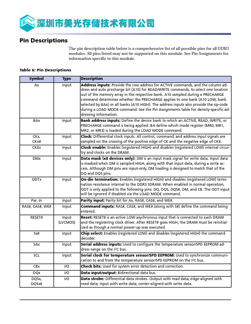
Pin DescriptionsThe pin description table below is a comprehensive list of all possible pins for all DDR3modules. All pins listed may not be supported on this module. See Pin Assignments forinformation specific to this module.Table 6: Pin Descriptions质量等级领域:宇航级IC、特军级IC、超军级IC、普军级IC、禁运IC、工业级IC,军级二三极管,功率管等;应用领域:航空航天、船舶、汽车电子、军用计算机、铁路、医疗电子、通信网络、电力工业以及大型工业设备祝您:工作顺利,生活愉快!以深圳市美光存储技术有限公司提供的参数为例,以下为MT16KTF1G64HZ-1G6E1的详细参数,仅供参考Functional Block DiagramFigure 2: Functional Block Diagram (PCB 0900, R/C-F)S1#BA[2:0]A[15/14:0]RAS#CAS#WE#CKE0CKE1ODT0ODT1RESET#BA[2:0]: DDR3 SDRAMA[15/14:0]: DDR3 SDRAMRAS#: DDR3 SDRAMCAS#: DDR3 SDRAMCKE0: Rank 0CKE1: Rank 1ODT0: Rank 0VVVVVVCommand, address and clock line terminationsCK[1:0]CK#[1:0]Rank 0 = U1, U2, U7, U9, U11, U12, U17, U19Rank 1 = U5, U6, U8, U10, U15, U16, U18, U20DDNote: 1.The ZQ ball on each DDR3 component is connected to an external 240Ω ±1% resistor that is tied to ground. It is used for the calibration of the component’s ODT and outputdriver.Figure 3: Functional Block Diagram (PCB 1569, R/C-F3)S1#BA[2:0]A[14:0]RAS#CAS#WE#CKE0CKE1ODT0ODT1RESET#BA[2:0]: DDR3 SDRAMA[14:0]: DDR3 SDRAMRAS#: DDR3 SDRAMCAS#: DDR3 SDRAMWE#: DDR3 SDRAMCKE0: Rank 0CKE1: Rank 1ODT0: Rank 0ODT1: Rank 1RESET#: DDR3 SDRAMVVVV DDSPDVVCommand, address and clock line terminationsCK[1:0]CK#[1:0]Rank 0 = U2, U3, U6, U7, U8, U11, U12, U15Rank 1 = U4, U5, U7, U19, U13, U14, U16, U18DDNote: 1.The ZQ ball on each DDR3 component is connected to an external 240Ω ±1% resistor that is tied to ground. It is used for the calibration of the component’s ODT and outputdriver.。
VK3266
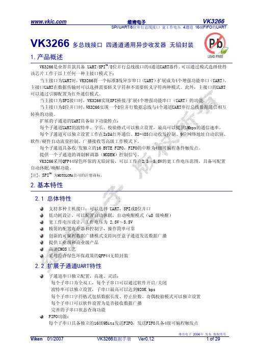
表7.1 全局寄存器列表
寄存器地址[3:0]
寄存器名称 类型
寄存器功能描述
(XX) 0000
RSV
无
保留
(XX) 0001
GCR
R/W
全局控制寄存器
(XX) 0010
GMUCR
R/W
全局主串口控制寄存器
(XX) 0011
GIR
R/W
子通道串口串行数据输出。 TX 将串行数据输出到与其连接的器件引脚。
硬件复位引脚,低电平复位有效 中断输出信号,低电平有效。建议外接上拉电阻,典型取值5.1K 电源 2.5V~5.5V工作范围 地 晶振输入; 当CLKSEL=0时,外部晶振连接到该引脚和OSCO引脚构成一个晶 体振荡电路。 晶振输出;当CLKSEL=0 时,外部晶振连接到该引脚和OSCI引脚构成一个晶 体振荡电路。 时钟选择:
6.1封装图
Viken 01/2007
VK3266数据手册 Ver0.12
维肯电子 2006年 发布 版权所有
3 of 29
维肯电子
VK3266
SPI/UART/8位并行总线接口 宽工作电压 4通道 16级FIFO的UART
44 GND 43 OSCI 42 OSCO 41 CLKSEL 40 CLKIN 39 VCC 38 RTS3 37 RX3 36 TX3 35 CTS3 34 RTS1
错误检测:
支持奇偶校验错,数据帧错误及溢出错误检测
支持起始位错误检测
每个子串口可以软件设置为是否接收数据广播
内置符合SIR标准的IrDA红外收发编解码器,传输速度可达115.2K bit/s
2.3 UART主接口特性
主接口为标准的三线UART串口(RX,TX,GND),无需其它地址信号、控制信号线 可编程波特率设置,最高速度可以达到1M bit/s 可选择的奇校验,偶校验和无校验模式 业界首创的不需地址线控制的串口扩展方式,通过芯片内置的协议处理器实现多串口扩展 UART主接口可以通过引脚设置为红外模式 UART主接口可以通过引脚选择是否采用转义字符模式
K60核心板说明与扩展板_SD-Ex-D_对接说明
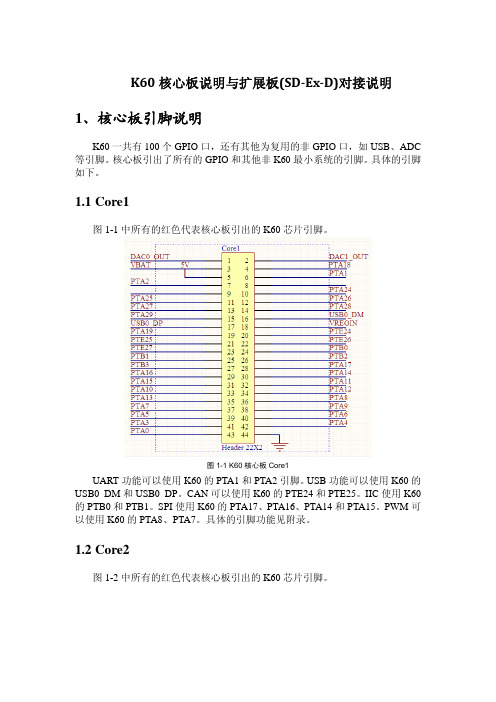
K60核心板说明与扩展板(SDExD)对接说明 1、核心板引脚说明K60一共有100个GPIO口,还有其他为复用的非GPIO口,如USB、ADC 等引脚。
核心板引出了所有的GPIO和其他非K60最小系统的引脚。
具体的引脚如下。
1.1 Core1图1-1中所有的红色代表核心板引出的K60芯片引脚。
图1-1 K60核心板Core1UART功能可以使用K60的PTA1和PTA2引脚。
USB功能可以使用K60的USB0_DM和USB0_DP。
CAN可以使用K60的PTE24和PTE25。
IIC使用K60的PTB0和PTB1。
SPI使用K60的PTA17、PTA16、PTA14和PTA15。
PWM可以使用K60的PTA8、PTA7。
具体的引脚功能见附录。
1.2 Core2图1-2中所有的红色代表核心板引出的K60芯片引脚。
图1-2 K60核心板Core2可以使用K60的ADC1_SE16和ADC0_SE16。
具体的引脚功能见附录。
1.3 Core3图1-3中所有的红色代表核心板引出的K60芯片引脚。
图1-3 K60核心板Core3具体的引脚功能见附录。
2、核心板与大板对接在设计电路时,考虑到与旧的扩展板兼容,做了如下设计,保证K60核心板与扩展板兼容。
以下图片中的蓝色表示大板的功能,红色代表核心板引出引脚。
2.1 Core1图2-1 Core1引脚定义2.2 Core2LCD使用K60的PTE可以实现,具体功能见参考代码。
图2-2 Core2引脚定义AD5和AD9分别接K60的ADC1_SE16和ADC0_SE16。
2.3 Core3可以使用K60的PTC口实现LED功能,具体实现见参考代码。
图2-3 Core3引脚定义3、附录:144引脚资源简明表3.1 硬件最小系统引脚K60N512VM100芯片电源类引脚,BGA封装22个,LQFP封装27个,其中BGA 封装的芯片有五个引脚未使用(A10、B10、C10、M5和L5)。
SMC电磁阀样本
3.2
0.30 0.80
注) 2位单电控、4/2→5/3 (A/B→R1/R2)的值。
适合缸径 (mm)
~ø50
~ø80
插座引出方向
上方引出
可快速变更(F.P组件)
只要压一下手动按钮,插座的引出方向便可由上方变更成侧向。 由侧向变为上方的场合,不用手动操作按钮。
侧向引出
丰富的集中配线方式
S 组件 (串行传送)
F P T 组件 (D型辅助插座)
组件 (扁平电缆插座)
组件 (端子台盒)
L 组件 (导线引出)
M 组件 (多针插座)
EX5se0ri0es
25针
26针
保护构造
20针
可对应IP67
保护构造 可对应IP67
● 为了配线作业及维护容易,6种方式已标准化,4种方式的保护构造对应IP67。 ● 对S组件,有输入输出形式。(网关单元除外)
注3)英制尺寸为以下记号。
·N1: ø1/8"
·N3: ø5/32"
·N7: ø1/4"
·NM: 混合
上配管弯头为LN□、下配管弯头为BN□。
端板种类(仅对应EX600的S组件记入)
无记号 无端板 2 电源M12插头(最大供给电流 2A) 3 电源7/8英寸插头(最大供给电流 8A)
注)无SI单元的场合为无记号。
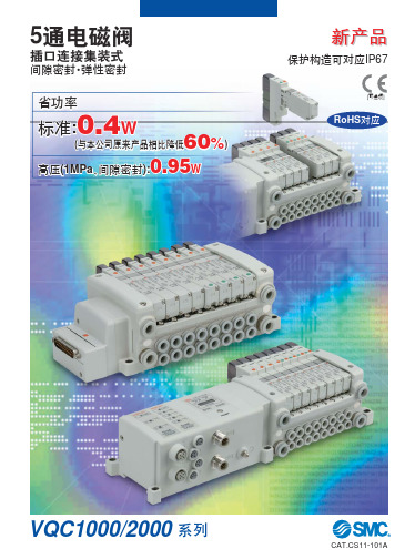
5通电磁阀
插口连接集装式
间隙密封·弹性密封
省功率
标准:0.4W
60 (与本公司原来产品相比降低
%)
0.95 高压(1MPa、间隙密封):
W
新产品
保护构造可对应IP67
[可选项]
RoHS对应
VQC1000/2000 系列
TM1638芯片详细手册

LED 驱动控制专用电路 TM16381©Titan Micro Electronics Ver1.2概述TM1638是带键盘扫描接口的LED(发光二极管显示器)驱动控制专用电路,内部集成有MCU 数字接口、数据锁存器、LED 高压驱动、键盘扫描等电路。
主要应用于冰箱、空调 、家庭影院等产品的高段位显示屏驱动。
特性说明采用功率CMOS 工艺 显示模式 10 段×8 位 键扫描(8×3bit)辉度调节电路(占空比8 级可调) 串行接口(CLK,STB,DIO)振荡方式:RC 振荡(450KHz+5%) 内置上电复位电路采用SOP28封装管脚定义:GRID1GRID2GRID3GRID4GND DIO CLK STB K3K2SEG1/KS1SEG2/KS2SEG3/KS3SEG4/KS4SEG8/KS8SEG7/KS7SEG6/KS6SEG5/KS5SEG9SEG10K1VDDGRID5GRID6GRID7GRID8GNDLED 驱动控制专用电路 TM16382©Titan Micro Electronics Ver1.2管脚功能说明:符号管脚名称说明DIO数据输入/输出在时钟上升沿输入/输出串行数据,从低位开始; STB 片选 在上升或下降沿初始化串行接口,随后等待接收指令。
STB 为低后的第一个字节作为指令,当处理指令时,当前其它处理被终止。
当STB 为高时,CLK 被忽略 CLK 时钟输入 上升沿输入/输出串行数据。
K1~K3 键扫数据输入 输入该脚的数据在显示周期结束后被锁存SEG1/KS1~ SEG8/KS8 输出(段) 段输出(也用作键扫描),P管开漏输出 SEG9~SEG10 输出(段) 段输出,P管开漏输出 GRID1~GRID8输出(位) 位输出,N管开漏输出 VDD 逻辑电源 5V±10% GND逻辑地接系统地▲ 注意:DIO口输出数据时为N管开漏输出,在读键的时候需要外接1K-10K的上拉电阻。
XP367使用手册
是否正常
JP101 跳线错误或 CPU 故障
检查跳线 JP101 是否接 2-3; 如仍不正常请更换卡件
5 资料版本说明
资料版本号 XP367 使用手册(V1.0)
表 5-1 版本升级更改一览表 适用产品型号
适用模块版本:XP367-10.10.00
更改说明
6
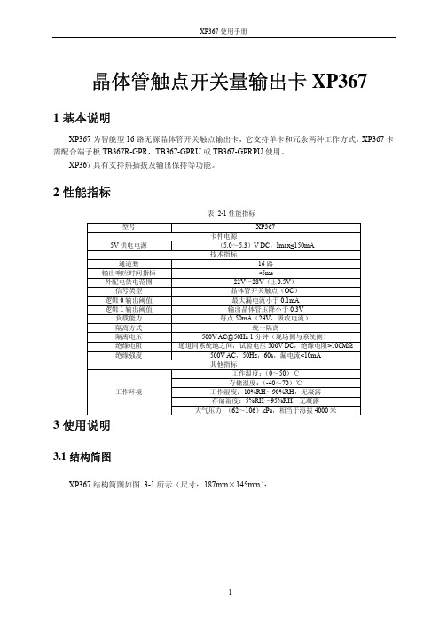
3.1 结构简图
XP367 结构简图如图 3-1 所示(尺寸:187mm×145mm):
1
XP367 使用手册
3.2 指示灯说明
图 3-1 XP367 结构简图
LED 指示灯 意义
状态 暗 常亮 闪
FAIL(红)
故障指示
正常 自检故障 CPU 复位
表 3-1 指示灯说明
RUN(绿) WORK(绿)
配合 TB367-GPRU 时的接口特性图如图 3-3 所示。
图 3-3 配合 TB367-GPRU 时的接口特性图(以第一、二通道为例) 3
XP367 使用手册
配合 TB367R-GPR 时的接口特性图如图 3-4 所示,图中以通道一、二、三为例分别描述三种接 线方式。
图 3-4 配合 TB367R-GPR 时的接口特性图(以第一、二、三通道为例) 4
运行指示
工作/备用
不运行 CPU 故障
微机原理16位32位CPU(8086)
S6-S3:输出CPU的工作状态。 S6:指示8086/8088当前是否与总线相连, S6=0,表示 8086/8088当前与总线相连。 S5:表明中断允许标志当前的设置。 S5=0,表示CPU中断是关闭的,禁止一切可屏蔽中断源的 中断请求;S5=1,表示CPU中断是开放的,允许一切可屏 蔽中断源的中断申请。
出一个“准备好”信号,之后CPU才会自动脱离TW状态而进入T4状态。
• ⑤在T4状态,总线周期结束。
2.1.2 8086的引脚信号和工作模式
1. 最小模式和最大模式的概念
根据所连的存储器和外设规模的不同,使它们可以在两种模式下工 作: (1)最小模式:
在系统中只有一8086/8088CPU。 (2)最大模式: 有两个或两个以上的CPU,一个为主处理器8086/8088, 另一个为协处理器8087/8089。 数值运算协处理器8087, 输入输出协处理器8089。
奇
进
偶
借
标
位
志
标
志
1-有进Байду номын сангаас借位 0-无进、借位
1-低4位向高4位有进、借位 0-低4位向高4位无进、借位
④标志寄存器
根据功能,标志可以分为两类:状态标志和控制标志 状态标志:表示前面的操作执行后,ALU所处的状态,这种状态像某
种先决条件一样影响后面的操作。 控制标志:表示对某一种特定的功能起控制作用。指令系统中有专门
2.1.1 8086的编程结构
在编程结构图中,从功能上划分,8086分为两大部分:即 总线接口部件BIU(Bus Interface Unit) 执行部件EU(Execution Unit)
honeywell-2316说明书
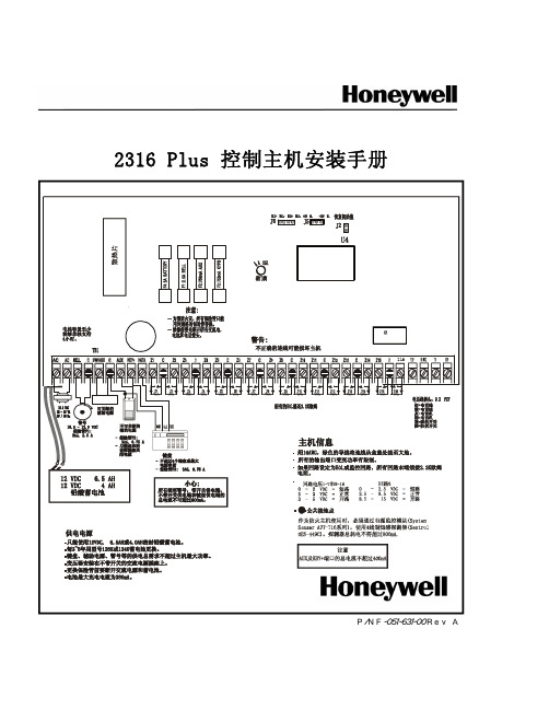
2316 Plus控制主机安装手册目录手册使用说明 (3)家居配置 (3)安装 (3)控制主机接线 (4)系统加电 (5)键盘启动 (6)编程选项 (7)主机编程 (7)对液晶键盘编程 (8)安装员须知 (24)重要通知 (24)测试 (24)看门狗指示灯 (24)电话线路问题 (24)键盘操作指令集 (25)常见问题解答 (26)减少误报注意事项 (28)注释 (29)报警系统的局限性 (32)2316 Plus控制主机编程表格 (33)2316Plus控制主机安装手册键盘操作指令集LED键盘和ALPHA II键盘的大部分指令功能是相同的,只有少数的指令是ALPHA II键盘专用的。
下面的指令适用于LED及ALPHA II两种键盘:功能 注释按键布/撤防有延时[密码] [#]旁路防区 (n)[n] 是防区号码 # 1 - 16; 可能需要密码 [密码] [旁路] [n] [#]门铃开/关可能需要密码[密码] [*] [5] [#]用主码修改密码必须从用户1开始[主密码] [*] [0] [#] [用户号码][新密码] [#] [新密码] [#]清除报警记忆[*] [1] [#]退出编程[*] [#]火警键盘启动[F] (按住 3 秒)组旁路或布防布防系统,CL 30 - 3F, 数据位 3设定的组旁路防区都被旁路。
可能需要密码(留守布防) [密码] [*] [4] [#]组旁路或即时布防同上,但系统即时布防。
可能需要密 [密码] [*] [4] [7] [#] 或者码(即时留守布防)[密码] [*] [7] [4] [#]即时布防布防系统,延时防区转换成即时防区 [密码] [*] [7] [#](有外出延时,无进入延时), 可能需要密码键盘启动遥控编程若CL 0B(3)中使能; 可能需要密码 [密码] [*] [0] [2] [#]紧急救助键盘启动 [E] (按住 3 秒)紧急报警键盘启动 [P] (按住 3 秒)辅助电源复位复位设备接在5、6端子 [*] [6] [2] [#]主机复位 [Master 密码] [*] [6] [8] [#]电池测试电池电压低恢复以后用 [*] [6] [4] [#]警号测试可能需要密码 [密码] [*] [6] [3] [#]报警中心测试可能需要密码 [密码] [*] [6] [1] [#]步测 [*] [6] [0] [#]以下指令仅对 ALPHA II键盘有效:功能 注释 按键布防音开关[*] [5] [4] [#]布防确认音开关[*] [5] [1] [#]背景光开关[*] [8] [#]显示键盘型号、版本[*] [9] [#]门铃开关[*] [5] [3] [#]预警开关[*] [5] [2] [#]以下所列为只适用于安装员的键盘指令:功能 注释 按键ALPHA键盘编程开始对键盘进行编程[安装员密码] [*] [0] [1] [#]ALPHA键盘测试[*] [6] [7] [#]主机复位[安装员密码] [*] [6] [9] [#]主机编程开始对控制主机进行编程[安装员密码] [*] [0] [#]2316Plus控制主机安装手册减少误报注意事项本章节的内容可以帮助您来减少系统误报,第一栏是编程指令地址和数据位,第二栏是建议编程值和简单描述:编程项指令地址、数据位功能描述布防/密码09 (2) 密码 可以防止未经授权用户操作键盘,象布撤防、旁路、启动遥控编程等都需要密码。
控制面板 CP600 2代 CP6407、CP6410、CP6415 操作指南说明书
—OPERATING INSTR UCTIONControl panels CP600 2nd generation CP6407, CP6410, CP6415Contents1Introduction (3)2Safety guide (4)2.1Safety guide (4)2.2Safety notices (4)2.3Markups (5)3Product overview (6)4Standards and approvals (7)4.1Product identification (7)5Technical specifications (9)6Technical data (11)6.1Dimensions (12)6.2Installation environment (13)6.3Safety instruction (14)6.4Installation procedure (14)7Connections (15)7.1CP600 2nd generation (15)7.2Serial port (16)7.3Ethernet port (16)8Power supply, grounding and shielding (17)9Battery (19)9.1Dispose of batteries (19)10Special instruction for use (20)11Cleaning faceplates (20)12Getting started (20)13System settings (21)14Unpacking and packing instructions (23)2 3ADR010470, 3, en_USCONTROL PANELS CP600 2ND GENERAT IONCP600 2nd generation, 3, en_US 31 IntroductionThe operational guidelines described below are information on device technical data, installation, transportation, storage, assembly, use and maintenance. The Manual refers to the following models: PictureType DescriptionCP6407Operator interface with 7” color widescreen display and resistive touchscreenCP6410Operator interface with 10”4 color display and resistive touchscreeCP6415Operator interface with 15” color display and resistive touchscreen2Safety guide2.1Safety guideThe manual contains safety standards that must be respected for the personal safetyand to avoid damage.Indications of attention are divided into three levels of severity.2.2Safety notices4 3ADR010470, 3, en_USCONTROL PANELS CP600 2ND GENERAT ION2.3MarkupsEnumeration.Precondition for an operation instruction or a description.Operation instruction with one step.1. Operation instruction with several steps.Result of an operation.CP600 2nd generation, 3, en_US 53Product overviewCP600 2nd generation HMI products combine state-of-the-art features and great perfor-mance in a compact and robust design.They have been designed to offer competitive price/performance ratio for challenging indus-trial applications where robust devices are a requirement.These products feature a full die-cast aluminum housing. Compatibility with CP600 seriescut-out offers an easy upgrade path for the old series.CP600 2nd generation products have been designed to run PB610 software with outstandingcommunication and graphical options.•Efficient and secure Linux operating system•Gateway function with Server and Client OPC UA•aFull PB610 vector graphic support•Efficient unified programming strategy for web HMI applications6 3ADR010470, 3, en_USCONTROL PANELS CP600 2ND GENERAT ION4Standards and approvalsThe products have been designed for use in an industrial environment in compliance with the2014/30/EU EMC Directive.The products have been designed in compliance with:EN 61000-6-4EN 61000-6-2 EN 61000-4-2EN 61000-4-3EN 61000-4-4EN 61000-4-5EN 61000-4-6EN 61000-4-8EN 61000-4-29EN60945The installation of these devices into the residential, commercial and light-industrial environ-ments is allowed only in the case that special in measures are taken in order to ensure con-formity to EN 61000-6-3.The products are in compliance with the Restrictions on Certain Hazardous Substances(RoHS) Directive 2011/65/EUIn compliance with the above regulations the products are CE marked.4.1Product identificationThe product may be identified through a plate attached to the rear cover. You will have toknow the type of unit you are using for correct usage of the information contained in theguide.An example of this plate is shown in the figure below:Note: the CP6407 label is used as an example for CP600 2nd generation Series.CP600 2nd generation, 3, en_US 783ADR010470, 3, en_USInformation on type plate (example) Description Product model name CP6407Product part number 1SAP540710R0001Serial number S.N.: AAxxxxxxxxxxxxxxxxAA Product version ID V.: xxxxxxxxxxxxxxx Manufacturer addressABB AGEppelheimer Straße 82, 69123 HeidelbergGermanyCONTROL PANELS CP600 2ND GENERAT IONCP600 2nd generation, 3, en_US 95 Technical specificationsTouchscreen technology ResistiveBack-up battery3 V 50 mAh Lithium, rechargeable, not user-replaceable, model VL2330.Fuse AutomaticSerial port RS-232, RS-485, RS-422 software configurable Flash 4 GB RAM512 MBHardware clock Clock/Calendar with back-up battery Accuracy RTC (at 25°C) < 100 ppmEnvironmental conditions Operating temperature -20 … +60 °C (vertical installation) EN 60068-2-14 Storage temperature-20 … +70 °CEN 60068-2-1 EN 60068-2-2 EN 60068-2-14 Operating and storage humidity 5 … 85 % RH not-condensing EN 60068-2-30Vibrations 5 … 9 Hz, 7 mm; 9 … 150 Hz, 1 g p-p EN 60068-2-6 Shock± 50 g, 11 ms, 3 pulses per axis EN 60068-2-27 Protection classFront panel IP66, Rear IP20EN 60529Electromagnetic Compatibility (EMC) Electrostatic discharge immunity test8 kV (air electrostatic discharge)4 kV (contact electrostatic discharge)EN 61000-4-2Radiated, radio-frequency, electromagnetic field immunity test 80 MHz … 1 GHz, 10 V/m 1.4 GHz … 2 GHz, 3 V/m 2 GHz … 2.7 GHz, 1 V/m EN 61000-4-3Burst immunity test±2 kV DC power port±1 kV signal lineEN 61000-4-4Surge immunity test ±0,5 kV DC power port (line to earth) ± 1 KV dc power port (line to line) ±1 kV signal line (line to earth) EN 61000-4-5Immunity to conducted disturbances inducted by radiofrequency field0.15…80 MHz, 10 VEN 61000-4-6Power frequency magnetic field immunity testEnclosure, 50 Hz, 30 A/m EN 61000-4-8Voltage dips, short interruptions and voltage variations immunity test Port: DC mains; Level:0% duration: 10 ms 20 spaces by 1 sTest executed on the 24 VDC of the EUTEN 61000-4-29Durability informationBacklight service life (LED type) 40000 hr. or more(Time of continues operation until the brightness of the backlight reaches 50 % of the rated value when the ambient temperature is 25 °C) - see Note 1Note 1: Extended use in environments where the ambient temperature is 40 °C or higher may degrade backlight quality/reliability/durability.10 3ADR010470, 3, en_US6Technical dataModel CP6407 CP6410 CP6415Display TFT Color / LED TFT Color / LED TFT Color / LEDColors 64K 64K 64KResolution 800X480 800X600 1024X768Diagonal 7” widescreen 10.4” 15”Dimming yes yes yesFlash 4GB 4GB 4GBSD card slot yes yes yesRAM 512MB 512MB 512MBSerial port RS-232,RS-485, RS-422software configurable RS-232,RS-485, RS-422software configurableRS-232,RS-485, RS-422software configurableEthernet port 2 10/100Mb 2 10/100Mb 2 10/100MbUSB port 2 Host interface ver-sion 2.01 max. 100mA, 1 max.500mA 2 Host interface ver-sion 2.01 max. 100mA, 1 max.500mA2 Host interface ver-sion 2.01 max. 100mA, 1 max.500mABattery rechargeable rechargeable rechargeableRTC yes yes yesVoltage 24Vdc (*) 24Vdc (*) 24Vdc (*)Current ratingat 24Vdc0.35A 0.40A0.70AWeight 1.0 Kg 2.0 Kg 3.5 Kg* 10-32VdcFor applications requiring compliance with EN 61131-2 and specifically in reference to 10 ms voltage dips, the power supply range voltage is 18-32Vdc.6.1DimensionsA B C H LCP6407 176 mm6.92”136 mm5.35”40 mm1.57”147,5 mm5.80”187,5 mm7.38”CP6410 276 mm10.86” 221 mm8.70”40 mm1.57”232,5 mm9.15”287,5 mm11.31”CP6415 381 mm15” 296 mm11.65”45 mm1.77”307,5 mm12.10”392,5 mm15.45”6.2Installation environmentAvoid prolonged exposition to direct sunlight to avoid the risk of overheating the device.The equipment is not intended for installation in contact with corrosive chemical compounds. Check the resistance of the front panel to a specific compound before installation.Do not use tools of any kind (screwdrivers, etc.) to operate the touch screen of the panel.In order to meet the front panel protection classifications, proper installation procedure must be followed:•The borders of the cutout must be flat•Screw up each fixing screw until the bezel corner get in contact with the panel.•The cutout for the panel must be of the dimensions indicated in this manual.The IP66 is guaranteed only if:•Max deviation from the plane surface to the cut-out: ≤ 0.5 mm•Thickness of the case where is mounted the equipment: from 1.5 mm to 6 mm•Max surface roughness where the gasket is applied: ≤ 120 μmA.CP64xxB.Installation cut-out6.3 Safety instruction6.4 Installation procedurePlace the fixing brackets contained in the fixing kit as shown in figure.7Connections7.1CP600 2nd generation1.Serial port2.Ethernet Port 03.Ethernet Port 1B Port V2.0, max. 500 mAB Port V2.0, max. 100 mA6.Power Supply7.SD Card Slot7.2 Serial portThe serial port is used to communicate with the PLC or with another type of controller. Different electrical standards are available for the signals in the PLC port connector: RS-232, RS-422, and RS-485.The serial port is software programmable. Make sure you select the appropriate interface in the programming software.Pin RS-232RS-422, RS-4851 GNDGND23 TX CHA-4 RXCHB-56 +5V output +5V output7 CTS CHB+8 RTS CHA+ 9To operate in RS-485 pins 7-8 and 3-4 must be connected externally.The communication cable must be chosen for the type of device being connected.7.3 Ethernet portThe Ethernet port has two status indicators. Please see description in figure.YellowOFF: Valid link has NOT been detected ON: Valid link has been detectedGreenON: No activity BLINKING: Activity8Power supply, grounding and shielding The power supply terminal block is shown in the figure below.Pin Description1 +24 V DC (L+)2 Common (M)3 Ground3 conductors 1,5 mm2 wire size minimum, minimum temperature conductor rating 105 °C.The unit must always be grounded to earth with 1,5 mm2 wire size minimum. Grounding helpslimit the effects of noise due to electromagnetic interference on the control system.Earth connection will have to be done using either the screw or the faston terminal locatednear the power supply terminal block. A label helps identify the ground connection. Also con-nect to ground the terminal 3 on the power supply terminal block.The power supply circuit may be floating or grounded. In the latter case, connect to groundthe power source common as shown in figure (see below) with a dashed line. When using thefloating power scheme, note that the panes internally connects the power common toground with a 1 MΩ resistor in parallel with a 4,7 nF capacitor. The power supply must havedouble or reinforced insulation. The suggested wiring for the power supply is shown below.All the electronic devices in the control system must be properly grounded. Grounding must be performed according to applicable regulations.9 BatteryCP600 2nd generation panels are equipped with rechargeable Lithium battery, not user-re-placeable.The hardware real-time clock (date and time) is maintained by the battery.When the battery is fully charged, it ensures a period of 3 months of data backup at 25 °C.Location of the battery: See “broken circle” in the picture below.9.1Dispose of batteries10Special instruction for use•Install the HMI device according to the accompanying installation instructions.•Ground the HMI device according to the accompanying installation instructions.•Only qualified personnel may install the HMI device or repair it.•Ensure that the aeration holes are not covered.•Care shall be taken not to allow layers of dust to form on the faceplate of the HMI device in a way that might cause the accumulation of static charges.Keep the faceplate of the HMI device clean: the equipment must be cleaned only with asoft cloth and neutral soap product. Do not use solvents.•This device should not be used for purposes and methods other than indicated in this document and in the documentation accompanying the product.11Cleaning faceplates12Getting startedCP600 2nd generation control panels must be programmed with the software PB610.PB610 Panel Builder is a software tool that must be properly installed on a computerrunning Microsoft Windows.There are two options to transfer a PB610 application project to a CP600 2nd generation de-vice:Ethernet Connect the CP600 2nd generation device to the computer with an Ethernetnetwork connection. From PB610 choose the command Run/Download to tar-get. You may have to ensure that the proper firewall policy has been config-ured in the computer to allow PB610 Panel Builder to access the network.USB Create an Update Package using PB610 Panel Builder and copy it to a USBFlash drive.CONTROL PANELS CP600 2ND GENERAT ION CP600 2nd generation, 3, en_US 2113 System settingsCP600 2nd generation control panels have a system settings interface to allow configurationof system options.The user interface of System Settings is based on HTML pages accessible locally on CP600or in remote using a Web browser Chrome v44 or higher on port 443(https://IP /machine_config). Default username is “admin”, default password is “admin”.Use navigation menu on the left side of the screen to browse through the available options.The active item of menu is highlighted on the left side. The right side shows relatedinformation and settings. Based on the size of the CP600 2nd generation screen, both menuand content of selected item may be shown on screen or not.Two modes of operation can be selected in the System Settings:User ModePB610 runtime is running or the CP600 2nd generation device is in “factory default” status. System Mode PB610 runtime is not running or the CP600 2nd generation devicehas a software failure. System Mode includes all options available inUser Mode and offers in additions commands dedicated to systemupgrade and recovery not available when running in User Mode.Activation of System Settings in User Mode:PB610 runtime not runningPress “System Setting” button on the CP600 2nd generation screen. PB610 runtime running Recall context menu and select “System Settings”. To recallthe context menu click and hold any unused area of thetouchscreen for a few seconds.Default hold time is 2 seconds.Activation of System Settings in System Mode:Normal operation If PB610 runtime is not running: Press “System Setting” button onthe CP600 2nd generation screen to enter in System Settings inUser Mode.Select “Restart” → “Config OS” to reboot in System Mode.If PB610 runtime is running: recall context menu and select “SystemSettings”. To recall the context menu click and hold any unused areaof the touchscreen for a few seconds.Default hold time is 2 seconds to enter in System Settings in UserMode.Select “Restart” → “Config OS” to reboot in System Mode. Recovery operation If panel is not responsive, use the so-called “tap-tap” procedure.This procedure consists in tapping the surface of the touchscreenduring the device power-up phase. Tapping frequency must be high.You have to start tapping the touchscreen as soon as power hasbeen applied to the device. When the sequence has beenrecognized, the system shows the message: “TAP-TAP DETECTED”.At this point release touch to boot in User Mode without runningPB610 runtime or press and hold few seconds (selecting so“RESTART: CONFIG OS”) to boot in System Mode.System Settings includes options for basic settings of the device.Language Configure language used for System Settings menu only.System Show information about platform, status and timers (e.g. Systemon time, backlight on time).Logs Enable persistent log for BSP and allows to export it.Date & Time Change the device date and time, including time zone andNTP ServerNetwork Configure IP Address of Ethernet interface and the other networksettings like DNS, Gateway, DHCP, Hostname, routing and bridging. Services Enable/disable services. Example of services are: Open SSH server,Cloud services, SNMP and logging.Management Update of BSP components (Main OS, Config OS, Boot loader,XLoader), check for partitions consistence, update of splash screen,information about usage and size of partitions. The update of MainOS is available only in System Mode, the update of Config OS is onlyin User Mode.Display Adjust brightness, configure automatic backlight turnoff and selectCP600 2nd generation orientation (90°, 180°, 270° and 360°). Restart Restart the device. “Main OS” option restarts as per default in UserMode, “Config OS” option restart panel directly into System Set-tings in System Mode.Authentication Configure password for administrator (“admin”) and for the stand-ard user (“user”). Administrator has full access to System Settings(updates of BSP and other system components).Standard user has some limitations.22 3ADR010470, 3, en_USCONTROL PANELS CP600 2ND GENERAT ION CP600 2nd generation, 3, en_US 2314 Unpacking and packing instructions3A D R 010470, 3, e n _U S © Copyright 2020 - 2021 ABB.All rights reserved.—ABB AGEppelheimer Straße 8269123 HeidelbergGermanyPhone: +49 6221 701 1444Fax: +49 6221 701 1382E-Mail:****************.com /plc/automationbuilder Note:We reserve the right to make technical changes or modify the contents of this document without prior notice. With regard to purchase orders, the agreed particulars shall prevail.ABB AG does not accept any responsibility whatsoever for potential errors or possible lack of information in this document.We reserve all rights in this document and in the subject matter and illustrations contained therein.Any reproduction, disclosure to third parties or utilization of its contents – in whole or in parts – is forbidden without prior written consent of ABB AG.。
AD7616 16 通道 DAS 数据手册说明书

16通道DAS ,内置16位、双极性输入、双路同步采样ADC数据手册AD7616Rev. 0Document FeedbackInformation furnished by Analog Devices is believed to be accurate and reliable. However, no responsibility is assumed by Analog Devices for its use, nor for any infringements of patents or other rights of third parties that may result from its use. Specifications subject to change without notice. No license is granted by implication or otherwise under any patent or patent rights of Analog Devices. Trademarks andregistered trademarks are the property of their respective owners.One Technology Way, P .O. Box 9106, Norwood, MA 02062-9106, U.S.A.Tel: 781.329.4700 ©2016 Analog Devices, Inc. All rights reserved. Technical Support /cnADI 中文版数据手册是英文版数据手册的译文,敬请谅解翻译中可能存在的语言组织或翻译错误,ADI 不对翻译中存在的差异或由此产生的错误负责。
如需确认任何词语的准确性,请参考ADI 提供的最产品特性16通道、双路、同步采样输入 可独立选择的通道输入范围真双极性:±10 V 、±5 V 、±2.5 V5 V 单模拟电源,V DRIVE 电源电压:2.3 V 至3.6 V 完全集成的数据采集解决方案 模拟输入箝位保护具有1 MΩ模拟输入阻抗的输入缓冲器 一阶抗混叠模拟滤波器片内精密基准电压及基准电压缓冲器双通道16位逐次逼近型寄存器 (SAR)ADC 吞吐速率:2×1 MSPS通过数字滤波器提供过采样功能 灵活的序列器,支持突发模式 灵活的并行/串行接口SPI/QSPI/MICROWIRE/DSP 兼容 可选循环冗余校验 (CRC) 错误检查 硬件/软件配置 性能信噪比 (SNR):92 dB (500 kSPS 、2倍过采样) 信噪比 (SNR):90.5 dB (1 MSPS) 总谐波失真 (THD):−103 dB ±1 LSB INL (典型值),±0.99 LSB DNL (最大值) 模拟输入通道提供8 kV ESD 额定值 片内自检测功能 80引脚LQFP 封装应用电力线路监控 保护继电器 多相电机控制仪器仪表和控制系统 数据采集系统 (DAS)概述AD7616是一款16位DAS ,支持对16个通道进行双路同步采样。