CJ42W双门矩形重锤式锁风翻板阀(单层、双层)
江苏2015年第三季度人防门、人防封堵信息指导价

樘 樘 樘 樘 樘 樘 樘 樘 樘 樘 樘 樘 樘 樘 樘 樘 樘 樘 樘 樘 樘 樘 樘 樘 樘 樘 樘 樘 樘 樘 樘 樘 樘 樘 樘 樘 樘 樘 樘 樘 樘
43610 41270 57570 46890 58060 70920 60960 59260 71420 61020 65980 69440 78080 74120 92040 91100 96990 92520 48510 62140 67720 75330 81980 112110 105780 71230 87250 91680 100020 98130 3630 4230 4640 5070 5470 6570 9500 12150 21300 25090 25330
90 91 92 93 94 95 96 97 98 99 100 101 102 103 104 105 106 107 108 连通口双向受力双扇防护密闭门 109 110 111 112 113 114 115 坡道内开式双扇防护密闭门 116 117 118 119 120 钢结构单扇密闭门 121 122 123 124 125 126 127 128 钢结构双扇密闭门 129 130
樘 樘 樘 樘 樘 樘 樘 樘 樘 樘 樘 樘 樘 樘 樘 樘 樘 樘 樘 樘 樘 樘 樘 樘 樘 樘 樘 樘 樘 樘 樘 樘 樘 樘 樘 樘 樘 樘 樘 樘 樘
4780 5790 5550 6380 6080 6420 6350 6910 8760 7890 5290 4630 5530 4990 5610 5420 6190 5890 7070 6500 7050 6770 8940 7720 9510 3150 3410 3890 4160 4590 5040 5470 6120 4350 4920 5020 5580 5780 6090 8980 6320
麦克维尔风机盘管技术手册11

额定供热量W 额定输入 功率 W
优质空调薄壁紫铜管机械涨接双曲型百叶窗式铝翅片
风机
高精度、低噪声滚珠轴承单相电容运转式电机
不带回风箱 kg 带回风箱 电源 电加热kW 不带回风箱 kg 带回风箱 kg
安全防漏 机组凝结水盘为整体冲压一次成型,无 焊缝、焊点;难燃型保温材料整体一次 粘贴于水盘,杜绝滴漏水的现象。专门 设计的水盘带有一定的倾斜度,确保凝 结水迅速排出。
安装简单灵活 机组采用对称型设计,用户在现场可方 便的改变机组左右接管方向;带回风箱 的机组在现场可改变机组的回风方式。 机组安装省时省力。
注:冷轧钢板表面经环氧树脂喷塑处理,不锈钢水盘材质为304不锈钢。
5
卧式暗装风机盘管MCW机组
卧式暗装风机盘管MCW机组技术参数(二管制 2排管)
性能 额定风量m3/h 型号 H M L H H H H H H H H H H H H MCW200BT 340 279 170 1770 1140 3280 32 39 46 0.15 0.18 0.21 34.5 37 41.0 0.32 5 4 MCW300BT 510 418 255 2830 1980 5120 46 53 65 0.21 0.24 0.29 35.0 40.0 43.0 0.51 14 12 MCW400BT 680 558 340 3830 2570 6450 56 72 80 0.25 0.33 0.36 37.5 42.5 45.0 0.67 26 21 MCW500BT 850 697 425 4510 3205 7750 73 86 90 0.33 0.39 0.41 41.0 44.0 46.0 0.80 36 30 MCW600BT 1020 836 510 5115 3735 9090 93 107 109 0.42 0.48 0.49 45.0 45.5 47.5 0.88 18 14 1.6MPa 前弯多翼镀锌钢板离心式双吸叶轮 1 1 2 1 2 1 2 1 2 1 220V~/50Hz IP20 B Rc 3/4 锥管内螺纹 R 3/4 锥管外螺纹 675 815 915 995 1095 465/516/497 235 11.0 14.0 1.0/2.0 14.0 17.0 kg 13.0 16.6 1.0/2.0/3.0 16.3 19.9 15.4 19.4 220V~/50Hz 2.0/3.0/4.0 19.1 23.1 2.0/3.0/4.0 20.2 24.5 2.0/3.0/4.0 21.3 25.9 3.0/4.0/5.0 30.9 36.9 16.2 20.5 17.1 21.7 25.8 31.8 28.6 35.0 3.0/4.0/5.0 33.9 40.3 31.0 38.2 4.0/5.0/6.0 36.9 44.1 36.3 44.5 5.0/6.0/7.0 42.8 51.0 1425 1525 1725 1985 3 2 4 2 4 2 4 2 MCW800BT MCW1000BT MCW1200BT MCW1400BT 1360 1115 680 7610 5535 12830 133 142 162 0.61 0.65 0.74 44.5 46.5 48.0 1.31 40 35 1700 1394 850 8400 6680 15500 164 183 200 0.74 0.83 0.91 47.5 49.5 50.0 1.47 28 23 2040 1673 1020 10380 7765 18485 188 217 237 0.85 0.99 1.08 49.0 49.5 51.0 1.81 40 36 2380 1952 1190 11200 8955 20200 229 239 279 1.04 1.09 1.27 51.5 52.5 53.0 1.95 30 25
ADVK烟气电动三通蝶阀安装说明书22102C2911
烟气、高炉废气等高温气体介质
主要零部件材质
使用温度 阀体 阀板 阀杆 阀座 轴承 密封填料
≦425℃ Q235A 0Cr18Ni9(304) 2Cr13 0Cr18Ni9(304) 高温滚珠轴承 柔性石墨
≦500℃ 15CrMo 0Cr18Ni9(304) 15CrMo 0Cr18Ni9(304) 高温滚珠轴承 柔性石墨
1. 电动执行机构结构 .......................................................................................... 9 2. 手动操作......................................................................................................... 9 3. 行程凸轮的调整 ............................................................................................ 10 4. 手动限位的调整 ............................................................................................ 10 5. 电位器的调整 ............................................................................................... 11 6. 电路板的调整 ............................................................................................... 11
阀岛 VTSA 2 d 说明书

阀岛 VTSA阀岛 VTSA主要特性创新多用途可靠易于安装• 采用坚固金属壳体的高性能阀• 一个阀岛可组合五种阀规格 (阀宽65 mm需连接件)• 标准化的多针插头、现场总线接口和控制模块• 梦之队:总线型阀岛配电气终• 端CPX,强强组合带来:– 前瞻性的内部通信系统,用于控制阀和CPX模块– 一个阀岛可组合四种阀规格而无需连接件– 集成智能阀功能 VTSA-F-CB • 多种阀功能用于集成到更高等级的控制架构中,符合EN ISO 13849-1• 模块化系统,提供一系列配置选项• 最多可扩展至32个电磁线圈• 随时可进行更换和扩展• 集成创新功能模块• 进气板可实现灵活的进气以及可变的压力分区• 逆向工作• 压力范围大 –0.9 ... 10 bar, 流量范围 550 ... 4000 l/min• 多种阀功能• 阀电源 24 V DC阀岛 VTSA-F-CB• 串行通信位于气动部分• 最多 7 个电压分区 (其中 6 个通过 Profisafe 关断模块,一个附加电压分区通过 Uval 实现)• 每个电压区最多 24 片阀• 每个阀岛最多 96 个阀位和最多 64 个互连模块• 坚固耐用的金属元件–– 阀–– 气路板–– 密封件• 通过阀上的LED 快速排除故障,通过现场总线诊断• 阀片可快捷更换,可靠维修• 手控装置,有按钮式、按钮式/锁定式或隐藏式• 采用久经验证的活塞滑阀,耐用• 大而耐用的标签系统• 100% 持续通电率• 装配完毕且经过检测的阀岛,拿到即可安装• 减少选型、订货、安装和调试的费用• 牢固安装在墙面或H型导轨上。
• 通过四个螺丝气路板可以扩展,在金属支撑上的气口隔离非常可靠。
-H- 注意阀宽 65 mm 的主要特性、阀和功能在“适配阀宽 65 mm”ISO3 型一章中另有说明a页码 2262d Internet: /catalogue/...Subject to change – 2023/02阀岛 VTSA 主要特性111312[1] 快速安装: 直接用螺丝安装或H型导轨安装[2] CPX 诊断接口,用于手持式设备(气口和阀片诊断)[3] 气动接口,连接CPX[4] 阀宽 18 mm, 26 mm, 42 mm 和52 mm 可无需适配件就组合在一个阀岛上[5] 减少停机时间: 现场通过LED诊断[6] 可靠操作:手控装置,按钮式,按钮式/锁定式或隐藏式[7] 多用途: 32 个阀位/ 32 个电磁线圈一个阀系列,用于多种流量[8] 阀功能齐全[9] 模块化: 气源板便于创建多个压力分区以及多个额外排气和进气口[10] 实用: 气口口径大,流量优化,坚固的金属螺纹口或预装配QS 接头,用于标准化O.D.的气管[11] 实用:大标签[12] 可靠: 阀、输出和逻辑电压可分别关断[13] 简单的电接口– 现场总线接口连接 CPX– 多针插头接口,带预装配电缆或端子条 (Cage Clamp®)– 控制模块,连接CPX– AS-I 接口– 单个接口– IO-Link– I-Port配备选项阀功能• 2x 两位两通阀, 单电控, 气复位, 常闭• 2x 两位三通阀, 单电控– 常开– 常开, 可逆– 常闭– 常闭, 可逆• 2x 两位三通阀, 单电控– 1x 常开, 1x 常闭– 1x 常开, 1x 常闭, 可逆• 两位五通电磁阀––单电控, 气复位/弹簧复位––双电控––双电控, 带主控信号• 两位五通阀,用于特殊功能,单电控– 弹簧复位– 通过电感式传感器感测开关位置PNP 或 NPN输出– 意外启动保护EN 1037– 逆向工作• 三位五通电磁阀– 中压式– 中封式– 中泄式• 三位五通阀,用于特殊功能– 开关位置14 被保留(开关位置14 被保留,如果紧急停机/断电),开关位置12 无弹簧复位– 仅用于阀岛(插拔式)– 中泄式或中间位置1→2,4→5– 开关位置14 被保留– 气复位• 三位五通阀,用于特殊功能– 开关位置12 被保留(开关位置12 被保留,如果紧急停机/断电),开关位置14 无弹簧复位– 仅用于阀岛(插拔式)– 中泄式或中间位置1→4,2→3– 开关位置12 被保留– 气复位• 软启动阀,用于缓慢而安全地增压– 高度安全– 传感器功能反馈开关位置H--注意阀宽 65 mm 的主要特性、阀和功能在“适配阀宽 65 mm”ISO3 型一章中另有说明a页码 2263 2023/02 – Subject to change d Internet: /catalogue/...阀岛 VTSA主要特性连接选项单阀气路板上的阀, 插拔式单阀气路板上的阀, 方形插头或插拔式• 电接口为标准4针M12 插头或4针弹簧压接端子,用于用户配置• 可用外先导/内先导气源• 集成活塞位置感测• 电接口,符合EN 175301-803 类型C (方形插头) 或• 用于用户配置的4针弹簧压接端子• 开放式电缆现场总线接口 CPX 电气终端现场总线接口 CPX电气终端组合 VTSA-F-CB• 最大32 个阀位/最大32 个电磁线圈• 任意气源• 任意数量的压力分区• 串行通信位于气动部分• 最高4 个电压区,用于气动部分阀的负载电压• 在CPX 接口中可以灵活关断最高3个电压区 , 即可内部通过PROFIsafe 也可外部通过 3x M12实现• 先导开关阀,带集成的压力传感器和内部总线连接• 软启动阀,带集成的压力传感器 和内部总线连接• 真空发生器,三种性能设置,节气回路, 可选增加喷射次数(动力喷射器脉冲) 和 通过内部总线连接, 参数可以通过CPX系统进行配置阀岛,带单个接口阀岛,带多针插头接口AS-I 接口• 最大20 个阀位/最大20 个电磁线圈• 任意气源• 任意数量的压力分区• 最大32 个阀位/最大32 个电磁线圈• 平行的模块化阀链接• 任意气源• 任意数量的压力分区• 1到8 个阀位/最大8 个电磁线圈• 软启动阀,用于缓慢而安全地增压I-Port IO-Link• 最多 16 个阀位/最多 32 个电磁线圈• 连接至一个 I-Port 主站• 直接安装一个总线节点• 最多 16 个阀位/最多 32 个电磁线圈• 连接至一个 IO-Link 主站可组合• 阀宽 18 mm: VTSA 流量最高550 l/min, VTSA-F 流量最高700 l/ min• 阀宽 26 mm: VTSA 流量最高1100 l/min, VTSA-F 流量最高1350 l/min • 阀宽 42 mm: VTSA 流量最高1300 l/min, VTSA-F 流量最高1860 l/min• 阀宽 52 mm: 流量最高2900 l/min• 阀宽 18 mm, 26 mm, 42 mm,52 mm 和 65 mm 可组合在一个阀岛上(用适配件,但不适合VTSA-F-CB)阀岛 VTSA 符合:• ISO 15407-2 阀宽 18 和 26 mm• ISO 5599-2 阀宽 42 和 52 mm4d Internet: /catalogue/...Subject to change – 2023/0252023/02 – Subject to changed Internet: /catalogue/...阀岛 VTSA主要特性阀岛配置器a Internet: 主要信息VTSAVTSA-FVTSA-F-CB阀岛配置器用于帮助您选择适用VTSA 阀岛,更易于订购合适的产品。
开利42CE、42CN、42CL零件说明

版本号Ver.No.生效自Valid. date第页共页Page ofSP FCU0100101-15-2007风机盘管-卧式机组Fan Coil Unit–Horizontal Model Unit161版本号Ver.No.生效自Valid. date第页共页Page ofSP FCU0100101-15-2007风机盘管-卧式机组Fan Coil Unit–Horizontal Model Unit261产品编码Product Code42CE002-014版本号Ver.No.生效自Valid. date第页共页Page ofSP FCU0100101-15-2007风机盘管-卧式机组Fan Coil Unit –Horizontal Model Unit361版本号Ver.No.生效自Valid. date第页共页Page ofSP FCU0100101-15-2007风机盘管-卧式机组Fan Coil Unit –Horizontal Model Unit461版本号Ver.No.生效自Valid. date第页共页Page ofSP FCU0100101-15-2007风机盘管-卧式机组Fan Coil Unit –Horizontal Model Unit561版本号Ver.No.生效自Valid. date第页共页Page ofSP FCU0100101-15-2007风机盘管-卧式机组Fan Coil Unit –Horizontal Model Unit661版本号Ver.No.生效自Valid. date第页共页Page ofSP FCU0100101-15-2007风机盘管-卧式机组Fan Coil Unit –Horizontal Model Unit761版本号Ver.No.生效自Valid. date第页共页Page ofSP FCU0100101-15-2007风机盘管-卧式机组Fan Coil Unit –Horizontal Model Unit861版本号Ver.No.生效自Valid. date第页共页Page ofSP FCU0100101-15-2007风机盘管-卧式机组Fan Coil Unit –Horizontal Model Unit961版本号Ver.No.生效自Valid. date第页共页Page ofSP FCU0100101-15-2007风机盘管-卧式机组Fan Coil Unit –Horizontal Model Unit1061版本号Ver.No.生效自Valid. date第页共页Page ofSP FCU0100101-15-2007风机盘管-卧式机组Fan Coil Unit –Horizontal Model Unit1161版本号Ver.No.生效自Valid. date第页共页Page ofSP FCU0100101-15-2007风机盘管-卧式机组Fan Coil Unit–Horizontal Model Unit1261产品编码Product Code42CN004-008版本号Ver.No.生效自Valid. date第页共页Page ofSP FCU0100101-15-2007风机盘管-卧式机组Fan Coil Unit –Horizontal Model Unit1361版本号Ver.No.生效自Valid. date第页共页Page ofSP FCU0100101-15-2007风机盘管-卧式机组Fan Coil Unit –Horizontal Model Unit1461版本号Ver.No.生效自Valid. date第页共页Page ofSP FCU0100101-15-2007风机盘管-卧式机组Fan Coil Unit –Horizontal Model Unit1561版本号Ver.No.生效自Valid. date第页共页Page ofSP FCU0100101-15-2007风机盘管-卧式机组Fan Coil Unit –Horizontal Model Unit1661版本号Ver.No.生效自Valid. date第页共页Page ofSP FCU0100101-15-2007风机盘管-卧式机组Fan Coil Unit–Horizontal Model Unit1761产品编码Product Code42CL002-012版本号Ver.No.生效自Valid. date第页共页Page ofSP FCU0100101-15-2007风机盘管-卧式机组Fan Coil Unit –Horizontal Model Unit1861版本号Ver.No.生效自Valid. date第页共页Page ofSP FCU0100101-15-2007风机盘管-卧式机组Fan Coil Unit –Horizontal Model Unit1961版本号Ver.No.生效自Valid. date第页共页Page ofSP FCU0100101-15-2007风机盘管-卧式机组Fan Coil Unit –Horizontal Model Unit2061版本号Ver.No.生效自Valid. date第页共页Page ofSP FCU0100101-15-2007风机盘管-卧式机组Fan Coil Unit –Horizontal Model Unit2161版本号Ver.No.生效自Valid. date第页共页Page ofSP FCU0100101-15-2007风机盘管-卧式机组Fan Coil Unit –Horizontal Model Unit2261版本号Ver.No.生效自Valid. date第页共页Page ofSP FCU0100101-15-2007风机盘管-卧式机组Fan Coil Unit –Horizontal Model Unit2361版本号Ver.No.生效自Valid. date第页共页Page ofSP FCU0100101-15-2007风机盘管-卧式机组Fan Coil Unit –Horizontal Model Unit2461版本号Ver.No.生效自Valid. date第页共页Page ofSP FCU0100101-15-2007风机盘管-卧式机组Fan Coil Unit –Horizontal Model Unit2561版本号Ver.No.生效自Valid. date第页共页Page ofSP FCU0100101-15-2007风机盘管-卧式机组Fan Coil Unit –Horizontal Model Unit2661版本号Ver.No.生效自Valid. date第页共页Page ofSP FCU0100101-15-2007风机盘管-卧式机组Fan Coil Unit –Horizontal Model Unit2761版本号Ver.No.生效自Valid. date第页共页Page ofSP FCU0100101-15-2007风机盘管-卧式机组Fan Coil Unit –Horizontal Model Unit2861版本号Ver.No.生效自Valid. date第页共页Page ofSP FCU0100101-15-2007风机盘管-卧式机组Fan Coil Unit –Horizontal Model Unit2961版本号Ver.No.生效自Valid. date第页共页Page ofSP FCU0100101-15-2007风机盘管-卧式机组Fan Coil Unit –Horizontal Model Unit3061版本号Ver.No.生效自Valid. date第页共页Page ofSP FCU0100101-15-2007风机盘管-卧式机组Fan Coil Unit –Horizontal Model Unit3161版本号Ver.No.生效自Valid. date第页共页Page ofSP FCU0100101-15-2007风机盘管-卧式机组Fan Coil Unit –Horizontal Model Unit3261版本号Ver.No.生效自Valid. date第页共页Page ofSP FCU0100101-15-2007风机盘管-卧式机组Fan Coil Unit –Horizontal Model Unit3361版本号Ver.No.生效自Valid. date第页共页Page ofSP FCU0100101-15-2007风机盘管-卧式机组Fan Coil Unit –Horizontal Model Unit3461版本号Ver.No.生效自Valid. date第页共页Page ofSP FCU0100101-15-2007风机盘管-卧式机组Fan Coil Unit –Horizontal Model Unit3561版本号Ver.No.生效自Valid. date第页共页Page ofSP FCU0100101-15-2007风机盘管-卧式机组Fan Coil Unit –Horizontal Model Unit3661版本号Ver.No.生效自Valid. date第页共页Page ofSP FCU0100101-15-2007风机盘管-卧式机组Fan Coil Unit –Horizontal Model Unit3761版本号Ver.No.生效自Valid. date第页共页Page ofSP FCU0100101-15-2007风机盘管-卧式机组Fan Coil Unit –Horizontal Model Unit3861版本号Ver.No.生效自Valid. date第页共页Page ofSP FCU0100101-15-2007风机盘管-卧式机组Fan Coil Unit –Horizontal Model Unit3961版本号Ver.No.生效自Valid. date第页共页Page ofSP FCU0100101-15-2007风机盘管-卧式机组Fan Coil Unit –Horizontal Model Unit4061版本号Ver.No.生效自Valid. date第页共页Page ofSP FCU0100101-15-2007风机盘管-卧式机组Fan Coil Unit –Horizontal Model Unit4161版本号Ver.No.生效自Valid. date第页共页Page ofSP FCU0100101-15-2007风机盘管-卧式机组Fan Coil Unit –Horizontal Model Unit4261版本号Ver.No.生效自Valid. date第页共页Page ofSP FCU0100101-15-2007风机盘管-卧式机组Fan Coil Unit –Horizontal Model Unit4361版本号Ver.No.生效自Valid. date第页共页Page ofSP FCU0100101-15-2007风机盘管-卧式机组Fan Coil Unit –Horizontal Model Unit4461版本号Ver.No.生效自Valid. date第页共页Page ofSP FCU0100101-15-2007风机盘管-卧式机组Fan Coil Unit –Horizontal Model Unit4561版本号Ver.No.生效自Valid. date第页共页Page ofSP FCU0100101-15-2007风机盘管-卧式机组Fan Coil Unit –Horizontal Model Unit4661版本号Ver.No.生效自Valid. date第页共页Page ofSP FCU0100101-15-2007风机盘管-卧式机组Fan Coil Unit –Horizontal Model Unit4761版本号Ver.No.生效自Valid. date第页共页Page ofSP FCU0100101-15-2007风机盘管-卧式机组Fan Coil Unit –Horizontal Model Unit4861版本号Ver.No.生效自Valid. date第页共页Page ofSP FCU0100101-15-2007风机盘管-卧式机组Fan Coil Unit –Horizontal Model Unit4961版本号Ver.No.生效自Valid. date第页共页Page ofSP FCU0100101-15-2007风机盘管-卧式机组Fan Coil Unit –Horizontal Model Unit5061。
奇力速 SKP-32BC-60WN 電動起子控制器 使用說明書说明书
電動起子控制器操作手冊OPERATION AND MAINTENANCE MANUALSKP-32BC-60WN(In: AC 100~240V Out: DC 24V / 32V)奇力速工業股份有限公司KILEWS INDUSTRIAL CO., LTD.Important safety information enclosed.Read all these instructions before placing tool in service or operation this tool and save these instructions. It is the responsibility of the employer to place the information in this manual into the hands of the operator. Failure to observe the following warnings could result in injury. When using electric tools, Basic safety precautions should always be followed to reduce the risk of fire, electric shock and personal injury, including the following:1. Important Safety Instructions2. Operations Cautions3. Grounding Instructions4. Installation Instructions5. Specifications6. ServicingImportant Safety InstructionsWARNING!Read all instructions Failure to follow all instructions listed below may result in electric shock fire and/or serious injure. The term “power tool” in all of the warning listed below refer to your mains operated (corded) power tool or battery operated (cordless) power tool.SAVE THESE INSTRUCTIONS1) Electrical Safetya) Keep work area clean and well lit. Cluttered and dark areas invite accidents.b) Do not operate power tools in explosive atmosphere, such as in the presence of flammable liquids,gases or dust. Power tools creat sparks which may ignite the dust of fumes..c) Keep children, and bystanders away while operating a power tool. Distractions can cause you to losecontrol.2) Electrical Safetya) Power tool plugs must match the outlet. Never modify the plug in any way. Do not use any adapterplugs with earthed (grounded) power tools. Unmodified plugs and matching outlets will reduce risk of electric shock.b) Avoid body contact with earthed or grounded surfaces such as pipes, radiators, ranges and refrigerators. There is an increased risk of electric shock if your body is earthed or grounded.c) Don’t expose power tools to rain or wet conditions. Water entering a power tool will increase the risk of electric shock.d) Do not abuse the cord. Never use the cord to carrying, pulling or unplugging the power tool. Keep cord away from heat, oil, sharp edges or moving parts. Damaged or entangled cords increase the risk of electric shock.e) When operating a power tool outdoors, use an extension cord suitable for outdoor e of cord suitable for outdoor use reduces the risk of electric shock .3) Personal Safetya) Stay alert, watch what you are doing and use common sense when operating a power tool. Do not use power tool while you are tired or under the influence of drugs, alcohol, or medication. A moment of inattention while operating power tools may result in serious personal injury.b) Use safety equipment. Always wear eye protection. Safety equipment such as dust mask, non-skid safety shoes, hard hat, or hearing protection used for appropriate conditions will reduce personal injuries.c) Avoid accidental starting. Ensure the switch is in the off position before plugging in. Carrying power tools with your finger on the switch or plugging in power tools that have the switch on invites accidents. d) Remove any adjusting keys or wrench before turning the power tool on. A wrench or a key that is left attached to a rotating part of the power tool may result in personal injury.e) Do not overreach. Keep proper footing and balance at all times. This enables better control of the power tool in unexpected situations.f) Dress properly. Do not wear loose clothing or jewellery. Keep your hair,clothing, and gloves away from moving parts. Loose clothes, jewellery, or long hair can be caught in moving partsg) If devices are provided for the connection of dust extraction and collection facilitys, ensure these are connected and properly used. Use of these devices can reduce dust related hazards.h) If devices are provided for the connection of dust extraction and collection facilitys, ensure these are connected and properly used. Use of these devices can reduce dust related hazards.4) Power tool Use and Carea) Do not force the power tool. Use the correct power tool for your application. The correct power tool will do the job better and safer at the rate for which it was designed.b) Do not use power tool if switch does not turn it on or off. Any power tool that cannot be controlled with the switch is dangerous and must be repaired.c) Disconnect the plug from the power source before making any adjustments, changing accessories, or storing the power tools. Such preventive safety measures reduce the risk of starting the power tool accidentally.d) Store idle power tools out of reach of children and do not allow persons unfamiliar with the power tool or these instructions to operate the power tool. Power tools are dangerous in the hands of untrained users.e) Maintain power tools. Check for misalignment or binding of moving parts, breakage of parts and any other condition that may affect the power tools operation. If damaged, have the power tool repaired before use. Many accidents are cause by poorly maintained power tools.f) Keep cutting tools sharp and clean, Properly maintained cutting tools with sharp cutting edges are less likely to bind and are easier to control.g) Use the power tools, accessories and tool bits ect., in accordance with these instructions and in the manner intended for the particular type of power tool, taking into account the working conditions and the work to be performed. Use of the power tool for operations different from intended could result in a hazardous situation.5) SERVICEa) Have your power tool serviced by qualified repair person using only indentical replacement parts,This will ensure that the safety of the power tool is maintained.Additional information shall be providea) Instruction for putting into use1. Setting-up or fixing power tool in a stable position as appropriate for power tools which can be mountedon a support.2. Assembly3. Connection to power supply, cabling, fusing, socket type and earthing requirements.4. Illustrated description of functions.5. Limitations on ambient conditions.6. List of contents.b) Operating Instructions.1. Setting and testing.2. Tool changing.3. Clamping of work.4. Limits on size of work piece.5. General instructions for use.c) Maintenance and servicing.1. Regular cleaning, maintenance, and lubrication.2. Servicing by manufacture or agent, list of addresses.3. List of user-replaceable parts.4. Special tools which may be required.Operations Cautions1. Please read the operating manual thoroughly and comply with safety regulation to operate thisMulti-Function Controller.2. Please grasp the plug of power cord while plugging in or out the plugs of connecting cord of ElectricScrewdriver and power cord.3. Please fix the power controller to avoid any danger of pulling and dragging the power cord.4. Do not near oil, chemical materials or heated objects, also please be alert not to scratch the power cordby sharp object.5. This type of Controller can only be applied to Kilews Electric Screwdriver with Counter. Do not useElectric Screwdriver Controller on other types of machinery.6. In case of the Controller is overheated or overloaded with maximum current rating of fuse, thehigh-speed fuse will be melt down and cut off the power. If the Controller continues to jump off or has an abnormal switching reaction, please stop the operation immediately and send back the Controller for repair.7. When Electric Screwdriver is running, if slides Forward/Reverse Switch instantly, device will generate theprotection program to force Electric Screwdriver stop.8. Please do not disassemble Electric Screwdriver casually and try to repair it by self.9. When Controller is not in use, please turn the main power switch OFF and unplug the power.WARNING!DO NOT OPERATE THIS TOOL WITHOUTPROTECTIVE EARTH CONNECTEDGrounding InstructionsThe tool should be grounded while in use to protect the operator from electric shock. The tool is equipped with a three-conductor cord and three-prong grounding-type plug to fit the proper grounding-type receptacle. The green (or green and yellow) conductor in the cord is the grounding wire. Never connect the green (or green and yellow) wire to a live terminal.Green and yellow----- EarthBlue ------ NeutralBrown ------ LiveInstallation Instructions1. Use the controller voltage recommended in the specification of this manul.2. When using a commercial power supply be sure to set up circuit and safety breakers.You must also properly ground the mechanisms.3. The temperature and humidity should be kept at appropriate levels.4. Do not set up the power supply in a room that has poor ventilation and where it may beexposed to dust and metallic flakes.5. Do not put heavy object on top of power supply or pile thing on it.6. Attach the power supply securely to a flat, stable surface. If the power supply is put ahigh place, take special care to ascertain that there is no danger of it falling.7. Keep bystanders away. Do not permit unauthorized personnel to operate this controller.8. Do not set up the power supply near high voltage machinery or in an excessively noisyenvironment.9. Avoid setting up or storing the power supply in wet or oily environments or where itmight be exposed to corrosive or flammable gases.10. We emphasize that the power supply should be placed in stable, fixed location.SAVE THESE INSTRUCTIONNOTICEThe use of other than genuine KILEWS replacement parts may result in decreased controller performance and increased maintenance, and may invalidate all warranties.Maintenance and Inspection :1. The controller must be operated in top condition, one day working hour must be not more than eight hours.2. Please note don’t let the controller get over heated, every minute use 10~15 screws to operate.3. The frequency use of this electric screw driver is over eight hours a day, still it needs periodically testingand treatment. Every 5-6 months.1. The use of other than genuine KILEWS replacement parts may Result in decreased tool performanceand increased maintenance, and may invalidate all warranties.2. All repairs and maintenance of this tool and its word must be performed by an authorized servicecenter.3. KILEWS is not responsible for customer modification of tools for applications on which KILEWS wasnot consulted.4. Repairs should by made only by authorized, trained personnel. Consult your nearest KILEWSauthorized service center.5. It is the responsibility of the employer to place the information in this manual into the hands of theoperator.6.Please refer to Kilews website for the detail component list.DO NOT ATTEMPT TO REPAIR THIS EQUIPMENTAll repairs and maintenance of the Controller and its cordmust be performed by authorized service centerSAVE THESE INSTRUCTIONSDO NOT DESTROY操作前請閱讀全部說明(內附零件分解圖)警告為了安全起見,在使用電動螺絲起子控制器前請詳閱電動螺絲起子控制器操作說明書,且務必依照說明書指示操作,並注意所有的警示重要安全說明事項1.使用電動螺絲起子控制器說明書規定的電壓。
豪迈工业安全联锁设备说明书

豪迈2010 NO.1总第 9 期(Total No.9)英国豪迈集团刊物 中文版豪迈集团是世界工业安全领域的领导者。
豪迈的工业安全联锁设备在全球的市场占有率为65%,是当之无愧的世界工业安全联锁第一大品牌,在全球各地保护了无数生命和财产的安全。
【本期专题:豪迈工业安全】西气东输二线西段工程采用SFC 阀门安全联锁系统 P04耐德(Netherlocks)将向道康宁张家港有机硅项目提供机械联锁 P05柯施泰(Castell)安全联锁系统保护中国多个核电站P06培育中国的过程安全市场——访集团过程安全部CEO Mark Lavelle先生 P1CONTENTS联系人 Contact:张明 中国区首席代表Martin Zhang , Director, Halma China ************-116*********************刘兵斌 中国区市场经理Bryan Liu , Marketing Manager for China ************-111******************蒋亚 北京代表处办公室经理Jena Jiang , Of fice Manager ************-805*******************豪迈集团中文网站:创新产品 - INNOVATIONP 07 科尔康(CROWCON )推出GAS-TEC 烃气检测仪,进行气体泄露勘查和定位P 08 ELFAB 便携式爆破片安装辅助器获得ATEX 认证P 09 福帝斯(FORTRESS)联锁推出的MGARD 电压开关单元增强安全性和效率P 09 赛特福(STI)旋转锁保证机电设施的安全性能P 10 柯施泰(CASTELL)安全联锁的获取更为快速业务动态 - NEWS FLASHP 11 蔚海光学仪器(上海)有限公司正式开业P 12 百柯流体有限公司取得中国营业执照P 13 流体控制专家迪贝(DIBA )收购OMNIFIT 品牌P 13 水质分析专家百灵达(PALINTEST)新中文网站落成1高层访谈Management Interview《今日豪迈》(以下简称HT ):豪迈过程安全部在中国的子公司,如柯施泰(Castell )、Smith 流程控制(SFC )、耐德(Netherlocks )、福帝斯(Fortress ),以及STI 、HFS ,在2009年都经历了一轮高速成长,恭喜您。
重锤式双层卸料阀质量标准
重锤式双层卸料阀质量标准
重锤式双层卸料阀的质量标准主要包括以下几个方面:
1.结构简单:该阀为重力式卸灰阀,主要由锥形灰仓、带斜角的密封面、传动机构等组成。
采用双层结构是为了实现在第一层卸灰后在落料到第二层中间实现全密封,以防止野风吹入。
2.卸料及锁风性能:该阀既能够卸料又能够锁风,常被用作各类环保除尘设备的灰斗卸料装置及各种磨机、烘干机、除尘器灰斗料仓等设备的给卸料装置。
为了防止野风吹入,通常会采用电动驱动形式。
3.材质和耐磨性:重锤式翻板阀通常采用碳钢Q235-B的材质,焊接结构,一般很少有铸造材质的。
由于该阀在使用过程中需要承受物料冲击和摩擦,因此耐磨性是评价其质量的重要指标之一。
4.传动平稳和拆换备件少:重锤式翻板阀采用无冲击、无故障的重力机械传动方式,传动平稳。
同时,该阀拆换备件较少,降低了维护成本。
5.良好的锁风性能:电动双层重锤翻板阀因良好的锁风性能而被推广,特别是在对锁风要求高的场合,双层结构的应用更多。
6.工作频率和可靠性:电动双层重锤翻板阀可以确定开锁频率完成系统的给料与卸料,且具有较高的工作频率和可靠性。
总的来说,优质的重锤式双层卸料阀应具备结构简单、设计新颖、体积小、重量轻、操作方便、安全可靠、维修方便等特点。
在选择时,需要根据具体工况和使用要求进行评判。
开利42系列风机盘管机样本

风量范围: 340~2380m 3/h风机盘管机组42CE产品制造公司:上海一冷开利空调设备有限公司通惠空调设备厂 成都开利爱得瑞空调设备有限公司上海 (86-21) 2306 3000 北京 (86-10) 5775 7300 成都 (86-28) 6988 9350 西安 (86-29) 8762 0258 广州 (86-20) 8393 1313 苏州 (86-512) 6288 8120机组规格(风量=机组规格X170m 3/h )002:2X170=340m 3/h 003:3X170=510m 3/h ......CE :卧式暗装风机盘管水盘A :标准水盘B :长水盘D :加长不锈钢水盘冷、热盘管排数20:2排冷30:3排冷31:3排冷+1排热机外静压0:12Pa 标准型3:30Pa 带静压型5:50Pa 高静压型注:机组风量订货时如无特殊说明则视为额定风量42 C E 0 0 2 2 0 0 A L机组接管方向(以面对出风口来区分)L :左方向R :右方向产品系列42:风机盘管型号说明提供快速、准确的计算机选型程序340~2380 m 3/h风量开利独有的针对风机盘管的选型软件:根据选定的机组型号计算不同工况下的热工性能根据不同的性能要求选择适当的机组型号根据需求选择控制附件输出技术参数和图纸开利公司是美国联合技术公司(UTC )的成员之一,UTC 在全球500强排名第150位(2011年),其业务遍及世界各地的建筑工业和航空航天工业等领域。
1902年,开利博士发明第一套科学空调系统以来,开利的产品和系统解决方案已经成为大量世界知名建筑的首选。
2011年,开利销售额达到120亿美元,位居行业领先。
销售网络覆盖全球170多个国家,是当今世界最大的暖通空调产品制造商。
开利在中国员工人数超过2500名,全国范围内有超过60个销售及售后服务机构。
作为世界级生产工厂,开利拥有多条世界领先的机组和压缩机生产线,产品涵盖商用、家用中央空调主机及空气端产品。
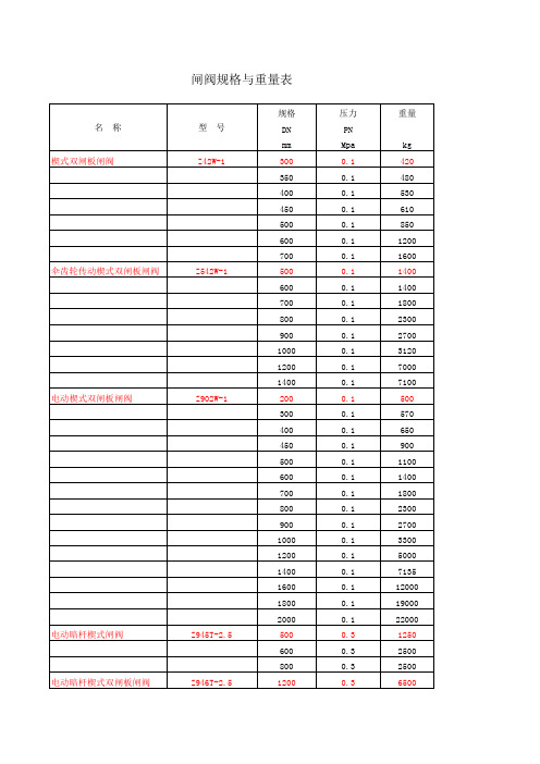
常见阀门重量参考明细
闸阀规格与重量表
型号 Z941W-10 Z44T-10
规格 DN mm 300 350 400 450 500 600 700 800 900 1000 100 125 150 200 250 300 350 400 450 500 600 700 40 50 65 80 100 125 150 200 250 300 350 400
名称 楔式闸阀 楔式闸阀 楔式闸阀
闸阀规格与重量表
型号 Z41Y-16I Z41T-16 Z41W-16P
规格 DN mm 65 80 100 125 150 200 250 300 50 65 80 100 125 150 200 250 300 350 400 500 50 65 80 100 125 150 200 250 300 50 65 80 100 125
压力 PN Mpa 1.0 1.0 1.0 1.0 1.0 1.0 1.0 1.0 1.0 1.0 1.0 1.0 1.0 1.0 1.0 1.0 1.0 1.0 1.0 1.0 1.0 1.0 1.0 1.0 1.0 1.0 1.0 1.0 1.0 1.0 1.0 1.0 1.0 1.0
重量
kg 15 18 22 28 35 61 75 130 170 263 360 495 76 120 150 195 220 360 600 750 76 120 150 195 220 360 600 750 8.5 17 25 30 38 52
名称 平行式双闸板闸阀
平行式双闸板闸阀
排污阀 内螺纹闸阀 内螺纹闸阀
闸阀规格与重量表
型号 Z44H-16
Z44T-16
PZ44H-16 Z11H-25 Z11Y-25
规格 DN mm 150 200 250 300 350 400 40 50 65 80 100 125 150 200 250 40 50 65 80 100 125 150 200 250 40 50 15 20 25 32 40 50 15 20
重锤翻板阀材质及用途和工作原理
重锤翻板阀又称气锁阀,电动锁风阀,锁风喂料机,重锤卸灰阀,重锤翻板阀分为双层重锤翻板阀,单层重锤翻板阀,广泛应用于化工,食品,建材,冶金,电力等行业。
该设备主要作为气旋分离器与除尘器以及各种烘干机,料仓等设备的给卸料装置,防止外风进入。
双层气锁阀主要利用上下阀门的在不同时间的开关使设备中间始终有一层阀板处于关闭隔断状态,来防止空气窜流。
如果是在正压输送下,气动的双层锁气阀还可起到平衡及增压阀的助流作用,以达到设备即能连续脉动给料的同时又具有锁气的功能,以满足气力输送粉粒体物料的要求。
整体结构设计坚固而紧凑,平稳可靠,精巧美观; 阀板和阀座交替开关,无滑动结构,密封性能强;可气力输送粉粒体物料系统,也可以用于一般的有压差的脉动卸料场合;法兰形状可以是圆形或方形;结构简单,维修方便; 抗磨损性能好,可适用于高温下的密封;不易产生卡堵现象;抛光精度可达300#,适合输送食品级的物料; 可根据用户实际需要选择多种主体材质:不锈钢(SS304,SS304L,SS316,316L,SS836L)碳钢等; 有多种驱动方式可以选择:气动,电动。
双层重锤卸灰阀结构特点:重锤式锁风翻板阀采用钢板焊接结构,配重杆自复位机构,结构紧凑,工作平稳可靠。
工作原理:双层重锤翻板阀的阀板在物料重力作用下自动开启,物料下落后,配重杠杆系统使阀板自动复位,防止野风吹入,从而完成物料的输送。
气动双层翻板阀沧州手动翻板阀单层重锤翻板阀盛康阀业双层重锤翻板卸灰阀是根据蘑菇头式、锥形阀等结构的卸灰阀,所存在的“体积大、泄漏率高、阀头易磨损以及卡料、心机易烧毁、在工业生产流程中无法进人自动控制”等缺陷而研制的一种结构简单、设计新颖的更新换代之产品。
双层重锤翻板卸灰阀采用插板结构卡料现象比其它结构卸灰阀的频率低且不易磨损;它集机、电、液、控于一体,可实现远距离控制、中央调度室监控和微机控制;双层重锤翻板卸灰阀通过调整调节螺钉可调整密封间隙;采用电液推杆作动力源,过载自动卸荷,白锁性好,不漏油,运行平稳;通电后,双层重锤翻板卸灰阀自动完成上、下阀之间互相交替工作,确保正压或负压卸料的工况下不会泄压,至设定的卸料量后自动停止,双阀全部关闭。
四管制冷热一体风冷热泵机组克莱门特尺寸-概述说明以及解释
四管制冷热一体风冷热泵机组克莱门特尺寸-概述说明以及解释1.引言1.1 概述概述本文将详细介绍四管制冷热一体风冷热泵机组克莱门特尺寸。
随着环境保护意识的增强和能源消耗的不断上升,绿色环保节能技术得到了广泛应用和推广,其中冷热泵技术成为了一种受到关注的解决方案。
冷热泵机组通过逆向工作原理,能够实现冷热能的互相转换,从而在空调和供暖系统中提供高效能源利用。
在过去的几十年中,传统的冷热泵机组主要采用两管制结构,即分别配备冷水和热水管道,无法同时实现供冷和供热功能。
而四管制冷热一体风冷热泵机组的出现解决了这一问题。
它通过增加两个额外的管道,实现了供冷和供热同时进行的功能。
这不仅提高了能源利用效率,还减少了系统运行成本。
在论文的后半部分,将重点介绍克莱门特尺寸。
克莱门特尺寸是指冷热泵机组最重要的性能参数之一,它直接关系到机组的制冷和供热能力。
本文将通过详细分析克莱门特尺寸的组成和计算方法,探讨其在机组运行过程中的作用和影响。
通过本文的研究和分析,希望能够深入了解四管制冷热一体风冷热泵机组克莱门特尺寸的相关知识,并为相关领域的研究和应用提供一定的参考价值。
同时,也希望通过本文的介绍,能够引起更多人对冷热泵技术的关注和研究,推动其在环境保护和能源节约方面的进一步发展。
文章结构部分的内容如下:本文将分为以下几个部分来详细介绍四管制冷热一体风冷热泵机组克莱门特尺寸的相关内容:1. 引言1.1 概述:介绍四管制冷热一体风冷热泵机组的基本概念和原理,以及其在实际应用中的重要性和优势。
1.2 文章结构:本部分,将详细说明文章的结构和各部分的内容安排,以便读者能够更好地理解整个文章的逻辑关系和内容安排。
1.3 目的:明确本文的写作目的,阐述研究的重要性和意义,以及对相关领域的促进作用。
2. 正文2.1 管制冷热一体风冷热泵机组:详细介绍四管制冷热一体风冷热泵机组的工作原理、结构组成和关键技术特点,探讨其在制冷和供热领域的应用前景。
门型号
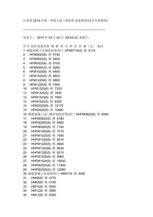
江苏省2010年第一季度人防工程防护设备指导价(含全部费用) -------------------------------------------------------------------------------- 发布于:2010年03月02日09:53:33 来源于:序号防护设备类型规格型号单位价格(元)备注1 钢筋混凝土单扇防护密闭门HFM0716(5) 樘51102 HFM0820(6) 樘57403 HFM0820(5) 樘59204 HFM0920(6) 樘61005 HFM0920(5) 樘62806 HFM1020(6) 樘64507 HFM1020(5) 樘69208 HFM1220(6) 樘68809 HFM1220(5) 樘746010 HFM1320(6) 樘732011 HFM1320(5) 樘780012 HFM1520(6) 樘785013 HFM1520(5) 樘830014 HFM2020(6) 樘1017015 HFM2020(5) 樘1099016 钢筋混凝土活门槛单扇防护密闭门HHFM0820(6) 樘649017 HHFM0820(5) 樘678018 HHFM0920(6) 樘696019 HHFM0920(5) 樘714020 HHFM1020(6) 樘721021 HHFM1020(5) 樘749022 HHFM1220(6) 樘841023 HHFM1220(5) 樘865024 HHFM1320(6) 樘883025 HHFM1320(5) 樘921026 HHFM1520(6) 樘968027 HHFM1520(5) 樘1063028 HHFM2020(6) 樘1140029 HHFM2020(5) 樘1208030 钢筋混凝土单扇密闭门HM0716 樘404031 HM0820 樘477032 HM0920 樘519033 HM1020 樘555034 HM1220 樘599035 HM1320 樘630036 HM1520 樘690037 HM2020 樘853038 钢筋混凝土活门槛单扇密闭门HHM0820 樘593039 HHM0920 樘639040 HHM1020 樘716041 HHM1220 樘759042 HHM1320 樘791043 HHM1520 樘865044 HHM2020 樘1033045 钢结构单扇防护密闭门GFM0716(6) 樘642046 GFM0716(5) 樘665047 GFM0820(6) 樘716048 GFM0820(5) 樘819049 GFM0920(6) 樘909050 GFM0920(5) 樘957051 GFM1020(6) 樘983052 GFM1020(5) 樘1092053 GFM1220(6) 樘1112054 GFM1220(5) 樘1199055 GFM1320(6) 樘1189056 GFM1320(5) 樘1327057 GFM1520(6) 樘1249058 GFM1520(5) 樘1543059 GFM2020(6) 樘1892060 GFM2020(5) 樘2140061 钢结构双扇防护密闭门GSFM2525(5) 樘3929062 GSFM3025(5) 樘4749063 GSFM3030(5) 樘5265064 GSFM4025(5) 樘5939065 GSFM4030(5) 樘7546066 GSFM5025(6) 樘7919067 GSFM5025(5) 樘8081068 GSFM6025(6) 樘8330069 GSFM6025(5) 樘9127070 钢结构活门槛单扇防护密闭门GHFM0820(6) 樘845071 GHFM0820(5) 樘896072 GHFM0920(6) 樘971073 GHFM0920(5) 樘1132074 GHFM1020(6) 樘1109075 GHFM1020(5) 樘1175076 GHFM1220(6) 樘1223077 GHFM1220(5) 樘1274078 GHFM1320(6) 樘1325079 GHFM1320(5) 樘1508080 GHFM1520(6) 樘1632081 GHFM1520(5) 樘1733082 GHFM2020(6) 樘1837083 GHFM2020(5) 樘2182084 钢结构活门槛双扇防护密闭门GHSFM2525(6) 樘4145085 GHSFM2525(5) 樘4724086 GHSFM3025(6) 樘5133087 GHSFM3025(5) 樘5645088 GHSFM4025(6) 樘6378089 GHSFM4025(5) 樘7065090 GHSFM4030(6) 樘7691091 GHSFM4030(5) 樘8670092 GHSFM5025(6) 樘8057093 GHSFM5025(5) 樘8926094 GHSFM5030(6) 樘8183095 GHSFM6025(6) 樘9758096 GHSFM6025(5) 樘10781097 GHSFM6030(6) 樘10865098 GHSFM7025(6) 樘11816099 GHSFM7025(5) 樘120800100 降落式双扇防护密闭门JSFM2525(5) 樘66150101 JSFM3025(5) 樘79030102 JSFM4525(5) 樘110880103 JSFM6025(5) 樘120520104 连通口双向受力双扇防护密闭门GSFMG3025(6) 樘64250 105 GSFMG4025(6) 樘82260106 GSFMG5025(6) 樘92620107 GSFMG6025(6) 樘103030108 坡道内开式双扇防护密闭门NSFM4025(6) 樘96910109 NSFM5025(6) 樘110380110 NSFM6025(6) 樘123850111 钢结构单扇密闭门GM0716 樘4900112 GM0820 樘5690113 GM0920 樘6300114 GM1020 樘6810115 GM1220 樘7400116 GM1320 樘8930117 GM1520 樘12560118 GM2020 樘14560119 钢结构双扇密闭门GSM2525 樘31490120 GSM3025 樘40070121 GSM3030 樘42210122 GSM4025 樘47610123 GSM4030 樘57750124 GSM5025 樘63520125 GSM6025 樘73500126 GSM6030 樘82400127 钢结构活门槛单扇密闭门GHM0820 樘5810 128 GHM0920 樘6590129 GHM1020 樘7450130 GHM1220 樘8370131 GHM1320 樘9700132 GHM1520 樘14130133 GHM2020 樘15610134 钢结构活门槛双扇密闭门GHSM2525 樘35490 135 GHSM3025 樘47520136 GHSM4025 樘56460137 GHSM4030 樘66410138 GHSM5025 樘73040139 GHSM5030 樘79150140 GHSM6025 樘84520141 GHSM6030 樘94770142 GHSM7025 樘102680143 降落式双扇密闭门JSM2525 樘46700144 JSM3025 樘59410145 JSM4025 樘70560146 JSM5025 樘86750147 JSM6025 樘96370148 JSM7025 樘121920149 防护密闭屏蔽门FMP0820(5) 樘18460150 FMP1020(5) 樘22360151 FMP1320(5) 樘27010152 FMP1520(5) 樘29030153 密闭屏蔽门MP0820 樘15020154 MP0920 樘15950155 MP1020 樘16890156 MP1220 樘17980157 MP1320 樘19470158 MP1520 樘21230159 HKP600(5)樘18900160 HKP800(5)樘20300161 HKP1000(5)樘23900162 密闭屏蔽观察窗MGCP1208 樘14470163 电控防护密闭门DFM1020(5) 樘42060164 DFM1320(5) 樘47520165 DFM1520(5) 樘50830166 电控密闭门DM1020 樘39380167 DM1320 樘43640168 DM1520 樘47970169 单扇防护防火密闭门FFHM0820(6) 樘13940170 FFHM1020(6) 樘16790171 FFHM1220(6) 樘18520172 FFHM1320(6) 樘19850173 FFHM1520(6) 樘22670174 单扇防火密闭门FHM0820 樘6890175 FHM1020 樘7840176 FHM1220 樘9340177 FHM1320 樘11100178 FHM1520 樘13480179 密闭观察窗MGC1008 樘3720180 MGC1208 樘4200181 胶管式防爆波活门KJH200(5)樘1540182 KJH300(5)樘2000183 KJH400(5)樘4600184 KJH500(5)樘5680185 KJH600(5)樘7370186 KJH800(5)樘11470187 KJH1000(5)樘12600188 悬摆式防爆波活门H300(5) 樘1640189 HK400(5) 樘4330190 HK600(5) 樘6210191 HK800(5) 樘7560192 HK1000(5) 樘9580193 连通口双向受力防护密闭封堵板FMDB3030(6)框樘9780 FMDB3030(6)板22340194 FMDB3030(5)框樘9780FMDB3030(5)板23460195 FMDB4030(6)框樘11430FMDB4030(6)板29760196 FMDB4030(5)框樘11430FMDB4030(5)板31420197 FMDB5030(6)框樘13070FMDB5030(6)板37170198 FMDB5030(5)框樘13070FMDB5030(5)板37920199 临空墙防护密闭封堵板LFMDB4025(6)框樘10920 LFMDB4025(6)板32730200 LFMDB4027(5)框樘11270LFMDB4027(5)板36920201 LFMDB5025(6)框樘12610LFMDB5025(6)板43250202 LFMDB5027(5)框樘12950LFMDB5027(5)板45640203 LFMDB6027(6)框樘14650LFMDB6027(6)板57170204 LFMDB7030(5)框樘16010LFMDB7030(5)板71270205 手动密闭阀DN200 个430206 DN300 个540207 DN400 个780208 DN500 个1310209 DN600 个2000210 DN800 个3290211 DN1000 个4190212 电动密闭阀DN200 个3000213 DN300 个3200214 DN400 个3700215 DN500 个4400216 DN600 个6300217 DN800 个7500218 DN1000 个9080219 过滤吸收器500型个5800220 SR78-1000 个7500221 油网滤尘器LWP-X D2 个1800 管式222 LWP-X D3 个2200 管式223 LWP-X D4 个2600 管式224 LWP-X D5 个3300 管式225 LWP-X D6 个4700 管式226 LWP-X D7 个5800 管式227 LWP-X 个310228 LWP-D 个380229 自动排气活门YF-D200 个370230 YF-D250(AL) 个400231 脚踏两用风机SR900 个3430 2人232 DJF-1 个4170 4人233 超压排气阀PS-D250 个2100 FSH-250注:1、以上所列常用设备均选自《人民防空工程防护设备选用图集》RFJ01-2008。
TOM-4000电动推拉门说明书

TOM-4000MOTORPARA PUERTAS CORREDERASAtención! Antes de efectuar la instalación, leer atentamente el presente manual, que es parte integrante de este producto.Nuestros productos si son instalados por personal cualificado capaz de la evaluación de riesgos, cumplen con la norma UNI EN 12453, EN 12445La marca CE es conforme con la directiva europea R&TTE 99/05CECONTENIDO EMBALAJE1-Motorreductor para correderas 1- Kit Placas de Final de Carrera1-Llaves de desbloqueo254196785380V/230V -TrifásicoPeso máximo por hoja4000Kg - 380VCon cuadro trifásico 5000kg - 230V Con cuadro inverterAlimentación del Motor230 /380VacCorriente absorbida por el motor2,5 A Potencia del motor eléctrico750 W Desbloqueo mecánico para maniobra de emergenciaCon Llave Temperatura de funcionamiento -25° C / +70° CPeso 40 Kg IngranajeZ16 Clase de protección IP 54 Final de CarreraElectromecánicoPROSPECTO AUTOMATISMO TIPO Y NOMENCLATURA COMPONENTESInstalación óptima1-Motor2-Fotocélula externa3-Indicador luminoso intermitente 4- Antena5-Fotocélula interna 6-Cremallera 7-Selector de llave 8- Emisor9-Central electrónicaDATOS TECNICOSDIMENSIONESCONEXION TIPO Y SECCION CABLES665 m m223 m m127 m m365 m m 225m m33mmCONSIDERACIONES PARA LA INSTALACIÓNFig. 1Fig. 3Fig. 4Ÿ L as operaciones de instalación y ensayo deben ser efectuadas únicamente por personal cualificado para garantizar un funcionamiento correcto y seguro de la cancela automática.Ÿ L a Empresa, se exime de toda responsabilidad por los daños derivados de instalaciones erradas por incapacidad y/o negligencia.Antes de proceder al montaje del automatismo controlar el buen funcionamiento de la cancela. Asimismo es conveniente verificar que la guía de desplazamiento a tierra (Fig. 1) no presente malformaciones, que se encuentre perfectamente nivelada y que el tope mecánico en apertura esté presente (Fig. 2), para evitar que la cancela salga de las guías superiores (Fig. 3).Tope mecánicoSección redondeadaSección de cantoŸ V erificar que la guía de desplazamiento superior (Fig. 3) esté fijada firmemente y que la cancela se desplace libremente.ŸVerificar que las ruedas (Fig. 4) utilizadas sean las apropiadas para el tipo de guía a tierraFig. 2MODALIDAD DE INSTALACIÓN Predisponer una funda eléctrica en corrispondencia de el agujero.apropiado.Ÿ Crear una excavacion a tierra demedida adecuada.Ÿ Pasar las fundas de los cables porlos orificios.Ÿ Nivelar y cementar la placa.Abrir la tapa frontal, quitar la carcasadel motor aflojando los tornillos de laparte inferior de la misma.Posicionar el motor sobre la placa defijacion y atornillarla por las tuercasM12 en dotacion.Atención: después del montajereemplazar el tapón aceite situadoen el lado del motor con elrespiradero.Fijar firmemente la cremallera en lacancela, dejando una distancia2-3mmde 2 a 3 mm. desde el piñón del motor(Fig.3).Fig. 3 Procedimiento de desbloqueo1.Abrir la tapa frontal.(Fig. 4)2. Insertar la llave hexagonal suministrada3.Rotar en sentido horario para desbloquear y contrahorario para bloquear (Fig.5)INCONVENIENTES-CAUSAS Y SOLUCIONESNota - Si el inconveniente aún persiste, contactarse con el Revendedor mismo o con el Centro de Asistencia más cercanoADVERTENCIAS PARA LA SEGURIDADLas presentes advertencias constituyen una parte integrante y esencial del producto y deben ser remitidas al usuario. Leerlas atentamente, ya que brindan importantes indicaciones relativas a la instalación, al uso y al mantenimiento. Es necesario conservar el presente módulo y transmitirlo a los nuevos utilizadores del equipo. La errada instalación o el uso inadecuado del producto podría representar una fuente de grave peligro.INSTRUCCIONES PARA LA INSTALACION• La instalación debe ser efectuada por personal profesionalmente competente y respetando la legislación local, estatal, nacional y europea vigente.• Antes de iniciar la instalación controlar la integridad del producto.• La puesta en obra, las conexiones eléctricas y las regulaciones deben ser efectuadas a “La Perfección”.• Los materiales de embalaje (caja, plástico, poliestireno, etc.) no deben ser dispersados en el ambiente ni dejados al alcance de los niños, ya que constituyen una potencial fuente de peligro.• No instalar el producto en ambientes donde existe peligro de explosión o interferidos por campos electromagnéticos. La presencia de gas o humos inflamables representa un grave peligro para la seguridad.• Preveer, en la red de alimentación, una protección para extratensiones y un interruptor/seccionador y/o diferencial adecuados para el producto y en conformidad con las normas vigentes.• El constructor queda eximido de cualquier responsabilidad en el caso de instalación de dispositivos y/o componentes incompatibles para la integridad del producto, la seguridad y el funcionamiento.• Para la reparación o sustitución de las partes se deberán utilizar exclusivamente repuestos originales.• El instalador debe proporcionar todas las informaciones relativas al funcionamiento, mantenimiento y utilización de los componentes y de todo el sistema.ADVERTENCIAS PARA EL USUARIO• Leer atentamente las instrucciones y la documentación adjunta.• El producto deberá ser destinado al uso para el que ha sido específicamente concebido. Cualquier otro uso debe considerarse como inapropiado y, en consecuencia, peligroso. Asimismo, las informaciones contenidas en el presente documento y en la documentación adjunta podrán ser objeto demodificaciones sin previo aviso. De hecho, son suministradas a título indicativo para la aplicación del producto. La sociedad queda eximida de cualquier responsabilidad.• Mantener los productos, dispositivos, documentación y cualquier otro elemento fuera del alcance de los niños.• En caso de mantenimiento, limpieza, avería o mal funcionamiento del producto, remover la alimentación y abstenerse de efectuar cualquier intento de intervención. Dirigirse únicamente al personal profesionalmente competente y encargado de realizar dicha tarea. El irrespeto por l o antes I indicado podría generar situaciones de grave peligro.Rev. 0-08/13SPLos datos y las imágenes son orientativosVDS se reserva el derecho de modificar en cualquier momento de las características de losproductos descritos en su única discreción, sin previo aviso.Via Circolare p.i.p. N° 1065010 Santa Teresa di Spoltore (PE) - ITALY Tel. +39 085 4971946 - FAX +39 085 4973849***************************************。
42CE使用说明书
42CE Fan Coil Unit (340~2720m 3/h )安装,操作及维修说明书Installation ,Operation and Maintenance Instructions请务必在机组的安装、使用和维修前认真阅读本说明书,开利公司的责任范围将不包括由于用户采取了本说明书规定之外的不适当操作而造成的机组损坏。
42CE风机盘管机组目录一. 安全须知 (1)二. 警示 (1)三. 安装维护 (2)1.安装 (2)2.接管道 (2)3.保温材料 (2)4.接线 (2)5.操作 (2)6.风机 (3)7.维修 (3)8.改变机组方向 (3)9.冬天的维护 (3)四. 服务条款 (4)五. 开利公司产品维修记录及保修卡 (4)安全须知42CE系列风机盘管在设计规范内运行时能够得到安全和可靠的服务,由于机组在使用压力、电机接线及装置设备等各方面的原因,只有经过培训的合格安装员和维修技师可以安装和维修本设备。
当在设备上工作时,必须遵守所有贴在机组上标签所示的安全措施,说明书上的安全说明,以及其它任何适用的安全预防措施。
●遵守所有安全规范●在搬运、安装和维修设备的时候须谨慎警示1.严格按照机组金属接线盒上的电气接线图(图1)和本说明书接线步骤接线。
2.严禁将2台以上不同规格的机组并线后接入同一控制开关。
3.请做好机组冬季的防冻保护工作,可以加防冻液或对机组进行放水处理。
4.机组出现异常运转情况,请关机与本公司维修站联系,切勿随意拆装维修。
(图1)安装1.移开机组上所有防护罩。
2.根据工作图所示使机组固定。
3.升起机组,并使机组定位在屋顶上。
注意:切莫利用排水管提升机组。
4.用4只10MM直径的螺栓,螺母和垫圈,使机组固定在屋顶上,校正机组水平,保证顺利的排水。
(图2)(图2)接管道1、根据国家和其他法规,制造所有管道连接件。
2、接通供水和回水管道。
3、连接排水管道。
保温材料1.机组所有进水管道和回水管道、冷凝盘的排水管道都应保温。
圆形双层锁气翻板卸灰阀
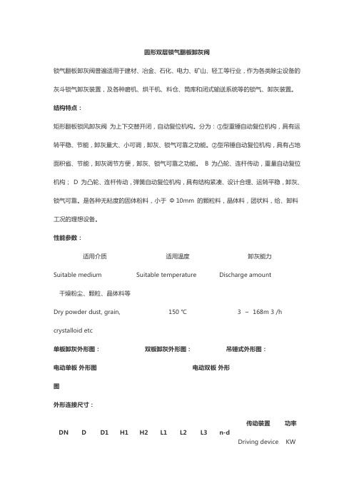
圆形双层锁气翻板卸灰阀锁气翻板卸灰阀普遍适用于建材、冶金、石化、电力、矿山、轻工等行业,作为各类除尘设备的灰斗锁气卸灰装置,及各种磨机、烘干机、料仓、筒库和闭式输送系统等的锁气、卸灰装置。
结构特点:矩形翻板锁风卸灰阀为上下交替开闭,自动复位机构。
分为:①型重锤自动复位机构,具有运转平稳、节能,卸灰量大、小可调,卸灰、锁气可靠之功能。
②型吊锤自动复位机构,具有占地面积省、节能,卸灰调节方便,卸灰、锁气可靠之功能。
B 为凸轮、连杆传动,重量自动复位机构; D 为凸轮、连杆传动,弹簧自动复位机构,具有结构紧凑、设计合理、运转平稳,卸灰、锁气可靠。
是各种无粘度的固体粉料,小于Φ 10mm 的颗粒料,晶体料,团状料,给、卸料工况的理想设备。
性能参数:适用介质Suitable medium适用温度Suitable temperature卸灰能力Discharge amount干燥粉尘、颗粒、晶体料等Dry powder dust, grain,crystalloid etc150 ℃ 3 ~ 168m 3 /h单板卸灰外形图:双板卸灰外形图:吊锤式外形图:电动单板外形图电动双板外形图外形连接尺寸:DN D D1H1H2L1L2L3n-d 传动装置Drivingdevice功率KW15023019550046014008- Φ 10BWY-15-590.6 20028024560050015008- Φ 10BWY-15-590.6 22030026560052015408- Φ 10BWY-15-590.6250350305600560161012- Φ10BWY-18-710.8300400355650600184012- Φ10BWY-22-71 1.1320420375750620198012- Φ12BWY-22-71 1.14005004558507008151630206016- Φ12BWY-2215-121 1.664505505058508008401680218016- Φ12BWY-2215-121 1.665006005559508508701740221020- Φ BWY-2215-121 1.66146007006559501920231020- Φ14BWY-2215-121 1.6672082077511002220238020- Φ14BWY-2715-121 3.1880090085512002520242024- Φ14BWY-2715-121 3.1810001130107014502940264028- Φ18BWY-3322-187 4.3。
威斯汀豪斯 16W72 双燃气膨胀机配件安装说明书

Save these instructions for future referenceINSTALLATION INSTRUCTIONSTwinning Kit 16W72For Single and Two Stage Gas-Fired Furnaces with ConstantTorque Blower MotorsThis manual must be left with the homeowner for future reference.(P) 507827-01*P507827-01*WARNINGImproper installation, adjustment, service, or maintenance CAUTIONLabel all wires prior to disconnection when servicing WARNINGRisk of electrical shock. Disconnect allApplicationThis accessory kit is used to operate two gas-fired furnaces that are intended to be “twinned together,” meaning connected in a shared duct system controlled by a single thermostat.• Do not twin more than two furnaces at a time.• Must be installed and wired in accordance with local codes.• Used for single-stage heating/single-stage cooling with a single-stage thermostat.•Used for two-stage heating/single-stage cooling with either a single-stage or two-stage thermostat.System OperationWith this twinning accessory kit, it is important to understand upon a call for heat from a single thermostat, that both circulation air blowers will come on and go off at the same time. In addition, the induced draft blowers of both furnaces will be energized, the pressure switch of each furnace will close, the gas valve of each furnace will open (either high or low fire depending on furnaces), and the burners of each furnace will ignite. Thirty seconds later, both circulation air blowers will be energized.When the heat demand is satisfied, the heating relays of each furnace are de-energized and close each furnace’s gas valve. Both furnace circulation air blowers will continue to run until the blower off fan period has been met.• Single-stage furnaces twinned together with a single-stage thermostat will operate each furnace at the same time.• Two-stage furnaces twinned together with a two-stage thermostat will operate each furnace such that first stage heat of each furnace operates at the same time.When second stage heat demand is needed, both furnaces will transition to high heat at the same time.• Two-stage furnaces twinned together with a single-stage thermostat will utilize control boards 7.5/10 min.stage transition. Each furnace must be set to same setting.InstallationTo twin two gas-fired furnaces, follow these directions along with the appropriate application section and wiring schematic.Single-Stage Heating and Cooling with Single-Stage Thermostat1. Mount DPST relay(s) (supplied with kit) next to theblower control board of Furnace 1. Use kit supplied self-tapping screws to mount DPST relay(s) to the control bracket.2. Connect the thermostat with Furnace 1, Furnace 2,and the DPST relay as shown in Figure 1 through Figure 3. Use the female quick connect terminals supplied in kit and the proper length of 18 gauge wire (field supplied) to complete wiring.3. After wiring is complete, cycle both heating and coolingmodes to verify both are working properly. FURNACE 1FURNACE 2ISO RELAYTHERMOSTATHEAT TWIN ONLYW1RCY1Y2GW2W1RCY1Y2GW2W1RCY1Y2GW2Figure 1.FURNACE 1FURNACE 2ISO RELAYTHERMOSTATCOOL TWIN ONLYW1RC Y1Y2G W2W1RC Y1Y2G W2W1RC Y1Y2G W2Figure 2.FURNACE 1FURNACE 2ISO RELAYTHERMOSTATFAN TWIN ONLYW1RC Y1Y2G W2W1RC Y1Y2G W2W1RC Y1Y2G W2Figure 3.Two-Stage Heating and Single-Stage Cooling with Single-Stage Thermostat1. Mount DPST relay(s) (supplied with kit) next to theblower control board of Furnace 1. Use kit supplied self-tapping screws to mount DPST relay(s) to the control bracket.2. Connect the thermostat with Furnace 1, Furnace 2,and the DPST relays as shown in Figure 1 through Figure 3. Use the female quick connect terminals supplied in kit and the proper length of 18 gauge wire (field supplied) to complete wiring.3. Set DIP switches of Furnace 1 and Furnace 2 controlboards to same furnace mode DIP switch setting for single stage thermostat, 2nd stage timing setting and blower off setting. See the furnaces’ installation instructions for additional detail.NOTE: Units are factory shipped with DIP switch settings for two-stage thermostat operation.4. After wiring is complete, cycle both high and lowheating modes and cooling modes to verify both are working properly.Two-Stage Heating and Single-Stage Cooling with Two-Stage Thermostat1. Mount DPST relay(s) (supplied with kit) next to theblower control board of Furnace 1. Use kit supplied self-tapping screws to mount DPST relay(s) to the control bracket.2. Connect the thermostat with Furnace 1, Furnace 2,and the DPST relays as shown in Figure 4 through Figure 6. Use the female quick connect terminals supplied in kit and the proper length of 18 gauge wire (field supplied) to complete wiring.3. After wiring is complete, cycle both high and lowheating modes and cooling modes to verify both are working properly.FURNACE 1 FURNACE 2THERMOSTAT TWO STAGE HEAT ONLYFigure 4.FURNACE 1 FURNACE 2THERMOSTATTWO STAGE COOL ONLYFigure 5.FURNACE 1FURNACE 2ISO RELAYTHERMOSTATFAN TWIN ONLYW1RCY1Y2GW2W1RCY1Y2GW2W1RCY1Y2GW2Note: Furnace transformers must be in phase while twinning.Figure 6.。
威克士NC

2 目录本手册包含正确安装和运行冷却塔的重要信息。
安装和运行冷却塔前请仔细阅读手册,然后按照所有说明运行。
请保存本手册,以便将来参考。
页码概貌 ............................................................................................................................. 3冷却塔运输....................................................................................................... 3接收冷却塔....................................................................................................... 3冷却塔位置....................................................................................................... 4冷却塔装配....................................................................................................... 4马达接线 ........................................................................................................... 5机械设备 ........................................................................................................... 6冷却塔启动....................................................................................................... 8冷却塔维护....................................................................................................... 14水质和排污....................................................................................................... 14冷却塔维护进度 .............................................................................................. 16维护进度表....................................................................................................... 19季节性停机说明 .............................................................................................. 20 延长停机 ........................................................................................................... 20附加信息 ........................................................................................................... 21故障检查及修理 .............................................................................................. 22下列定义的术语将在整本手册中使用,请注意各级风险和有关系到产品寿命的重要信息。
KGE42型风门开闭传感器语音型使用说明书

产品使用说明书KGE42型风门开闭传感器(语音型)执行标准: Q/MAS 18-2005版本号: Ver1.0出版日期: 2005.04.06重庆梅安森科技发展有限责任公司一、概述1、用途和适用范围KGE42系列风门开闭传感器是磁性驱动的位置开关传感器,系矿用本质安全型产品。
该产品可在煤矿井下有甲烷及煤尘爆炸危险的环境中,安装在井下巷道的各级风门上,用来监测风门的开闭状态,为通风管理提供风门状态信息,且能发出语音信息,并把检测到信号转换成各种标准信号传输给矿井监测系统,最终实现在地面对全矿井风门状态进行集中、连续、自动的采集、处理、监测。
2、特点该传感器系矿用本质安全型。
采用新型优化设计,具有结构新颖、安装使用方便、功耗低、适应性强、性能稳定可靠等特点。
3、型号组成及代表意义KG E 42登记序号风门开闭位置矿用传感器及敏感元件二、工作原理传感器的原理框图见图1图1 KGE42型风门开闭传感器原理框图KGE42系列风门传感器利用磁场感应测试原理,它将触发磁铁装在风门上,把开关组件安装在对应的门框上。
风门开闭时产生电信号,经信号变换、信号输出等环节,将风门开/闭信号送至分站或其它信号传输设备,再远传至地面中心站进行存储、显示或控制,从而实现对设备的集中连续监测监控;并能发出语音信号,警示用户风门开闭状态。
三、技术特征1、使用条件环境温度: 0℃~+40℃;相对湿度:≤95%(+25℃);大气压力: 80~106kPa;适用环境:煤矿井下有爆炸危险的场所。
2、主要技术指标工作电压: +12VDC~24VDC;工作方式:直接固定在风门和门框上;输出信号型式: A: 1mA/5mA制式(三线传输);B: 0mA/5mA制式(三线传输);C:+5mA/-5mA制式(四线传输);D: RS485通讯制式(四线传输);用户在选用时可提出具体配接信号要求。
防爆类型:矿用本质安全型,标志为“ExibI”;防护等级:IP54;运行显示:主、副风门其中一扇开时——报警灯闪烁,发出语音警示信息:“请关风门,谢谢!”主、副风门均开时——报警灯闪烁,发出语音警告信息:“为了您的安全,请随手关闭风门”主副风门均闭合时——报警灯灭,无任何信息。
