Valeport 106水流仪简明操作手册
卓越 超薄 數碼 恒溫 氣體 熱 水 器 使用手冊说明书

超薄數碼恒溫氣體熱水器I n s t a n t a n e o u s G a s Wa t e r H e a t e r內容Content請確定遵從Please make sure to follow如何操作How to Operate當有需要時請查看Please read when necessary安全操作注意事項 ........................................................ 2Cautions for safety operations第一次使用熱水器 ..................................................... 10To operate the heater for the first time使用熱水器方法 .......................................................... 11Operating Instructions日常檢查及保養 .......................................................... 13Daily inspection and maintenance熱水器修理指南 .......................................................... 15Trouble shooting of the heater規格 ............................................................................... 17Specifications維修服務 ...................................................................... 18Repair service各部份名稱 ..................................................................... 9Parts identifications適用於香港根據香港法例第51章(氣體安全氣體裝置技工及氣體工程承辦商註冊)規例規定,任何人如非註冊氣體裝置技工而安裝/接駁或修理這件氣體爐具即屬違法。
流速测算仪说明书
流速测算仪使用说明书文章来源:/esite/detail10077395.htm目录1:技术要求2:测量原理3:仪器的操作使用4:数据的存储5:流量计算6:存储数据查询7:仪器的维护8:仪器的全套设备9: 流速仪型号、延时输入表10:仪器软件操作说明注:本说明书中的参数只供参考,使用时应按照鉴定证书的参数为准便携式流速测算仪便携式流速测算仪是专门为水文站,水文地质调查,环保监测、灌区等部门而专门研制的新型仪器。
该仪器具有耗电省、功能齐全、自动化程度高、稳定可靠,适用性强等优点。
适用于接收各种转子流速传感器所产生的信号。
一:技术指标▲流速范围:0.05~7m/s▲精度:<1.5%▲显示:汉字液晶显示,4行32位▲存储:可存储100个断面数据▲通讯:标准RS232接口▲无线:具有无线接口,可与缆道等配套使用▲工作温度:-10℃~50℃▲工作电源:7.2V\\4200mAh,可充电二: 原理流速、流量计算:测流速时,由于水力推动转子流速仪旋转,流速仪内部信号装臵产生转数信号,便携式流速测算仪接收信号,再根据下面公式计算流速: V = K •N/T + C(m/s)。
式中V:测流时段内平均流速K: 桨叶水力螺距C: 流速仪校订常数T: 测流时间(单位为S)N: 时段内信号数本仪器使用时,K、C均为校订常数,测流时,只要测出T和N,即可算出流速V。
依据流量公式Q=V•S而设计,只要计算出断面截面积S并臵入就可求得流量Q(m ³/s)注该机流量适合管道和标准小渠道和标准出水口用。
三: 仪器的操作使用:仪器开机显示如图1所示:请输入流速仪型号→1 2图1: 型号设臵本仪器共设3个操作按键,如图2所示:换屏臵数移位图2:如上所示3.1 参数设臵操作:3.1.1用臵数键和移位键将流速仪型号臵入, 黑色闪烁光标(z)在哪个位臵闪烁可按下臵数键修改该位臵数据,按一下换位键将光标移到下一位臵。
如1206B流速仪臵入12即可,(具体型号看说明书最后一页)显示如下:请输入流速仪型号→0 0图3:按“臵数”键到显示2为止请输入流速仪型号→1 2图4: 型号设臵型号臵好后按换屏键进入仪器参数设臵显示图面同时保存以上设臵(如下图)。
水流计使用方法说明书
水流计使用方法说明书使用方法说明书一、产品说明本说明书主要介绍水流计的使用方法。
水流计是一种用来检测流体流量的仪器,适用于各种液体和气体的流量测量。
本水流计采用先进的技术和高精度传感器,能够准确、稳定地测量流体的流量。
二、使用前准备1.确认产品完整:在开始使用前,检查水流计是否完好无损,并确保配件齐全。
2.仔细阅读说明书:请认真阅读本使用方法说明书,了解产品的结构、性能和使用要求。
3.检查流体参数:在使用水流计时,需要了解被测流体的温度、压力和介质等参数,确保测量的准确性和安全性。
三、使用步骤以下是水流计的使用步骤:步骤一:安装与接线1.选择合适的安装位置:根据实际需要,选择合适的安装位置并固定水流计。
2.连接电源:将水流计的电源接线与电源线连接,确保电源供应稳定。
3.接线:将水流计的信号接线与检测设备接线端口连接,确保信号传输畅通。
步骤二:参数设置1.打开电源:接通电源并确认电源指示灯亮起。
2.进入设置界面:根据产品说明书,进入相应的设置界面。
3.设置参数:根据被测流体的实际参数,按照说明书中的指导进行参数的设置。
步骤三:校准1.开始校准:在校准前,请确保水流计已经预热并稳定工作。
2.按照校准操作说明:根据产品说明书中的校准操作说明,按照要求进行校准。
3.保存校准数据:根据说明书中的指引,将校准数据保存在水流计中。
步骤四:开始测量1.打开水流计:根据产品说明书中的指引,打开水流计并等待其初始化完成。
2.选择测量模式:根据需要选择合适的测量模式,并调整相应参数。
3.开始测量:按下开始按钮,水流计将开始测量流体的流量。
4.记录数据:在测量过程中,可以查看实时数据,并记录需要的数据。
步骤五:维护与保养1.定期清洁:根据产品说明书,定期清洁水流计,确保其正常工作。
2.保护仪器:使用水流计时,请避免剧烈震动和碰撞,保护仪器免受外界损伤。
3.定期维护:按照产品说明书中的要求,定期对水流计进行维护和保养。
四、注意事项1.安全使用:使用水流计时,请遵守相关安全操作规程,确保人员和设备的安全。
手持式多普勒流速流量仪使用说明书
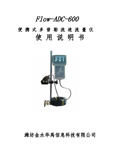
Flow-ADC-600便携式多普勒流速流量仪使用说明书潍坊金水华禹信息科技有限公司概述简便、快捷、准确、可靠、稳定的渠道与河流测量装置一直是各国流量测量专家的追求,受科学技术自身条件的限制,始终没能解决好这一难题。
但近几年美国将声学多普勒多点剖面流速测量技术应用在这一领域后,情况得到了根本性改变。
我公司引进Flow系列声学多普勒流速测量仪设计的流量测量系统已被广泛应用到水利、环保、城市供排水的流量、流速测量中。
应用声学多普勒效应简介多普勒效应是为纪念奥地利物理学家克里斯琴.约翰.多普勒而命名的,在声学领域中,当声源与接收体(即探头和反射体)之间有相对运动时,回声的频率将有所变化,此种频率的变化称之为频移,即多普勒效应。
现代社会中有大量应用这一物理原理而设计生产的仪表,如最常见的彩色多普勒超声二维结构图像仪、彩色多普勒血流图像仪,交通警测量汽车速度的微波测速仪以及水利学上的微波水表面流速仪等。
Flow-ADC-600 声学多普勒流速仪是应用当今最先进信号处理技术研发的多点、多层面流速分析仪,其最大特点是可任意按需要安装在被测河流或渠道侧面、底部或顶部,按现场情况任意设置向上、向下发射或向左、向右发射角度,从而准确测量出从水底到水面不同深层,从左到右不同距离上,根据多个流速数据、计算出平均流速。
根据现场水位的测绘能简单的测算各种规则或者非规则流体的截面面积绘制简单库容图。
大大简化了水利传统测流方法,并在准确性、稳定性,实时性上有了质的飞跃。
任意一个河流或渠道,只要有一台Flow-ADC-600测量仪,就能准确测出水的流态分布、流速数据及流量。
一、特点(1)、单只流速传感器,安装方便适合市政污下水管渠道、不满管管道、各种渠道、不规则河道、天然溪、排污口等流量测量并可隐蔽安装,可以做到长期稳定可靠工作。
(2)、既可顺流速、也可水位、水深方便统计。
(3)、大屏幕触摸屏,不仅有中文,还有配合图形,方便操作及流态分析。
型数字流速流向仪安全操作及保养规程

型数字流速流向仪安全操作及保养规程就像其他测试设备一样,数字流速流向仪需要得到妥善保养,以确保其准确性和可靠性。
本篇文章将会介绍如何操作及保养型数字流速流向仪。
安全操作因为型数字流速流向仪涉及到电源和酸碱液等的运用,因此在使用前,请阅读以下安全声明:在操作之前应先阅读使用说明书并按照本文所述的规定和操作来正确使用该型数字流速流向仪。
电源连接接通电源和断电时,必须遵循以下安全规则:1.操作前必须仔细检查电源连接线是否正常。
电源连接线应处于良好的状态下,无暴露电线或其他异常现象。
2.使用局部供电电源,控制电压在特定范围内。
根据仪器的额定电压,决定使用的电源,并确保其稳定在该仪器允许的电源标准的设定范围内。
3.在接通电源和断电时必须使用电源开关。
在电源开关处设置标签,以便在必要时切断电源。
4.不要让电源线垂直于地面上升或沿地面排列。
没有固定的电源线应位于单向电源线管中,或顺着墙壁和地板排列。
成分及酸碱液安全在使用型数字流速流向仪前,必须明确有关成分及酸碱液的危险性及相应的安全措施。
1.化学品要保持干燥、清洁和放置到规定好的存储区域。
储存区必须有明确的标示和分类,取出化学品时必须戴手套和护目镜,并使用密封容器存储化学物品。
2.在型数字流速流向仪的安装和操作时,必须使用经过检验和验证合适的化学品。
对于未知化学成分的液体,必须进行最小的数量的测试,以保证正确性和安全性。
3.处理酸碱液时务必戴上安全手套和保护眼镜。
将这些溶液储存在明确标示的区域,确保它们与其他物品隔离。
测量值记录如果记录测试值,可采用以下操作:•将手指放在液体中心上方并观察指针的位置。
(颜色要与背景区分开)•将其与测试表进行比较,并记录结果。
•结束测试后,请用酸洗液清洗仪器并及时关闭电源。
保养规程在使用型数字流速流向仪之前和之后的每次使用过程中,都必须保养仪器。
1.规则检查投影计的位置。
如果投影机的位置不正确,则可能会导致在测量中出现偏差。
通过调整投影仪的位置来解决问题。
Model106操作手册
Model 106自容式/直读式测流计安装& 8008 CDU操作手册VALEPORT LIMITED2013年5月目录Model 106 (1)自容式/直读式测流计 (1)安装& 8008 CDU操作手册 (1)1 简介 (3)1.1 一般描述 (3)2 系统描述 (3)2.1 设备 (3)2.2 甲板单元 (4)2.3 提供的设备 (4)2.4 客户供应 (4)3 安装 (4)3.1 机械安装 (4)3.2 电路连接 (5)3.3 串行数据格式 (6)3.4 电池 (6)4 USING 8008 CDU操作 (6)4.1 操作流程 (7)4.2 CDU记录的有关注意事项 (9)4.3 DATA REPLAY (9)4.4 外部连接 (9)4.5 打印机输出 (10)4.6 存储容量 (10)5 维护 (11)5.1 更换电池 (11)5.2 8008 CDU 电池更换 (11)5.3 螺旋桨 (12)5.4 一般说明 (12)5.5 O型圈尺寸 (12)5.6 备份锂电池 (13)6 校准 (13)附录 1 指标(见彩页) (13)附录 2 图解 (14)附录 3 接线图 (16)附录 4 发货前检查列表 (18)1 简介本手册涵盖了106型自容式/直读式测流计和8008显示控制单元配合使用的安装和操作手册。
手册还涵盖了一般维护程序、设备校准数据。
测流计和软件的操作包含在补充的DataLog软件手册中。
1.1 一般描述106型是基于螺旋桨式测量流速和流向的海流计,可选温度和深度参数传感器。
标准配置是自容式,可以选配直读式配置。
两种设备都可以通过电脑直接操作;还可以用8008控制显示单元控制直读:自容式:可以通过连接电脑和内置9路D型插头的甲板电缆设置采样和提取数据。
自容式测流计布放时不可能控制或从其读取数据。
直读式:RS232通讯可以通过外接4路Mil-Spec插头和电脑的短线(最大50m) 读取数据。
F56金属转子流量计现场调节
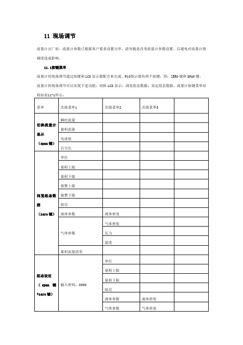
11 现场调节流量计出厂前,流量计参数已根据客户要求设置完毕,请勿随意改变流量计参数设置,以避免对流量计准确度造成影响。
11.1按键菜单流量计的现场调节通过按键和LCD显示器配合来完成。
P10指示器有两个按键,即:ZERO键和SPAN键。
流量计的现场调节可以实现下述功能:切换LCD显示;浏览组态数据;设定组态数据。
流量计按键菜单结构如表11-1所示:菜单次级菜单1 次级菜单2 次级菜单3切换流量计显示(span键)瞬时流量累积流量电流值百分比浏览组态数据(zero键)单位量程上限量程下限报警上限报警下限阻尼液体参数液体密度气体参数气体密度压力温度累积流量清零组态设定(span键+zero键)输入密码:0000单位量程上限量程下限阻尼液体参数液体密度气体参数气体密度压力温度累计时间间隔(L2/L21)输入密码:1111 主变量调零11.2操作说明11.2.1切换LCD显示闭合SPAN按键,流量计显示在“电流→百分比→主变量→累积流量”之间循环切换,当显示期望设置的显示变量时,断开按键,显示变量设置成功。
11.2.2浏览组态数据流量计正常工作状态下,连续闭合ZERO按键3秒,可以进入浏览组态数据模式。
进入浏览组态数据模式后,闭合ZERO按键,流量计显示在“单位→量程上限→量程下限→报警上限设定→报警下限设定→阻尼→被测介质参数→累计流量清零→正常显示”之间循环切换。
若流量计显示组态数据,1分钟内无按键闭合将返回正常显示。
在浏览过程中,报警上限设定、报警下限设定和累积流量清零可以进行设定。
11.2.3组态设定流量计正常工作状态下连续闭合SPAN键+ZERO键3秒,可以进入组态设定,密码登录界面。
各级对应的密码及功能如下:密码备注功能组态设定0000 单位、量程、阻尼、介质参数、累计时间间隔设定主变量调零1111 -注:请勿进入现场校准设定模式,进入此模式将会改变流量计校准数据,造成流量计不能使用。
11.2.4 LCD液晶各种显示页面图11-1 电流显示图11-2 百分比流量图 11-3 主变量(瞬时流量)图11-4 累积流量图11-5 单位图11-6 量程上图11-7位图 11-8量程上限图11-9 量程下限图11-10 报警上限图 11-11 报警下限图11-12 阻尼图11-13 气体密度图11-14 气体压力图11-5 气体温度图11-16液体密度图11-17 累积流量清零图11-18 密码输入图11-19 电流微调(4mA)图11-20 电流微调(20mA)12 开启12.1液体测量在开启阀门过程中,为避免突然打开阀门,形成水头冲击,损坏流量计,务必要缓慢地打开阀门!12.2气体测量在开启阀门之前,不要给管道加压,否则,如果阀门(例如:电磁阀)被突然打开,浮子将冲向上限位处,并可能损坏流量计,所以务必要缓慢地打开阀门!测量气体的流量计可以装配一个气动阻尼装置,以最大限度的减小浮子的震荡。
水测试仪用户手册说明书

50 1.47%
CANCEL - hold 5 sec
A graph will be plotted during the test time (180 seconds for the EasySHIP Test and 120 seconds for the Reagent B Test).
Test complete
Always start the test with the highest range selected, when in doubt about the approximate amount of water in your test oil. Overpressure can occur if an oil sample is tested with a very high water content on the low range 100-3000ppm. This can cause permanent damage to the pressure sensor.
5)Replace Lid
BACK
START
NB: The amount of oil and reagent used changes with the range. Always use gloves when handling EasySHIP Sachets.
*Squeeze all of the EasySHIP Paste into the centre of the cell ** Range 100 - 3000ppm = Add 35ml ReagA
Range 0.02 - 1.0%
WATER TEST
Range 0 - 10% Range 100 - 3000ppm
塑料排水板纵向通水量测定仪操作规程
塑料排水板纵向通水量测定仪操作规程
1、试样安装:将试件裁成约48cm长的试样,两头的滤膜各除去1cm,将试样的4只角剪成45°倒角,并小心装入管状乳胶膜内。
2、压力设定:开机后按压力设定键,再按调整键【加】和【减】再调整压力数值,按【确认】存入。
调整下限值、时间设定、调整零点后
开始试验。
3、通水:打开送水泵、进水口阀门,使溢流平衡水箱的溢流口中有水流出,持续一段时间,以使排水板中的空气排出和滤膜充分湿润,关
闭进水口阀门。
4、加压:打开工作容器的排水口和送水阀门,打开送水泵开关,通过送水口进水,至排水口有水流出时关闭进水口和排水口,打开加压泵
开关,通过加压泵加压至要求压力自动停止。
5、测试通水量:打开进水口,使溢水口1和溢水口2有水排出,排水板两头的水位差正好为20cm,水利梯度为0.5,检查压力是否为350Kpa,按照规范要求进行测试。
6、试验完毕后关闭电源,清理设备。
Proline Promass 100 PROFINET 微流计用户手册说明书
Products Solutions ServicesDescription of Device Parameters Proline Promass 100PROFINETCoriolis flowmeterGP01037D/06/EN/01.1571288055Valid as of version 01.00.zz (Device firmware)Proline Promass 100 PROFINET Table of contents Endress+Hauser 3Table of contents1Document information (4)1.1Document function .....................41.2Target group ..........................41.3Using this document ....................41.3.1Information on the document structure .......................41.3.2Structure of a parameter description .....................61.4Symbols used ..........................61.4.1Symbols for certain types of information ....................61.4.2Symbols in graphics (7)2Overview of the Expert operatingmenu (8)3Description of device parameters (10)3.1"System" submenu .....................133.1.1"Display" submenu ...............133.1.2"Diagnostic handling" submenu ......273.1.3"Administration" submenu .........343.2"Sensor" submenu ......................383.2.1"Measured values" submenu ........393.2.2"System units" submenu ...........463.2.3"Process parameters" submenu ......613.2.4"Measurement mode" submenu .....683.2.5"External compensation" submenu ...703.2.6"Calculated values" submenu ........753.2.7"Sensor adjustment" submenu .......793.2.8"Calibration" submenu ............893.2.9"Supervision" submenu ............903.3"Communication" submenu ...............913.3.1"Web server" submenu ............913.3.2"PROFINET configuration" submenu ..943.3.3"PROFINET information" submenu ...953.4"Application" submenu ..................963.4.1"Totalizer 1 to 3" submenu .........973.4.2"Viscosity" submenu .............1023.4.3"Concentration" submenu .........1023.5"Diagnostics" submenu .................1023.5.1"Diagnostic list" submenu .........1053.5.2"Event logbook" submenu .........1093.5.3"Device information" submenu .....1113.5.4"I/O module" submenu ...........1153.5.5"Sensor electronic module" submenu 1153.5.6"Display module" submenu ........1163.5.7"Min/max values" submenu .......1163.5.8"Heartbeat" submenu ............1253.5.9"Simulation" submenu .. (126)4Country-specific factory settings..1294.1SI units ............................1294.1.1System units (129)4.1.2Full scale values ...............1294.1.3On value low flow cut off .........1304.2US units ...........................1314.2.1System units ..................1314.2.2Full scale values ...............1314.2.3On value low flow cut off ........1315Explanation of abbreviated units..1335.1SI units ............................1335.2US units ...........................1335.3Imperial units .......................135Index (136)Document information Proline Promass 100 PROFINET 4Endress+Hauser1 Document information 1.1 Document function The document is part of the Operating Instructions and serves as a reference for parameters, providing a detailed explanation of each individual parameter of the Expert operating menu.1.2 Target group The document is aimed at specialists who work with the device over the entire life cycle and perform specific configurations.1.3 Using this document 1.3.1 Information on the document structure This document lists the submenus and their parameters according to the structure of the Expert menu (→ 8) menu that are available once the "Operator" user role or the "Maintenance" user role is enabled.1Sample graphic For information on the arrangement of the parameters according to the structure of the Operation menu, Setup menu, Diagnostics menu (→ 102), along with a brief description, see the Operating Instructions for the device.Proline Promass 100 PROFINET Document information Endress+Hauser 52Sample graphic For information about the operating philosophy, see the "Operating philosophy"chapter in the device's Operating InstructionsDocument information Proline Promass 100 PROFINET1.3.2 Structure of a parameter descriptionThe individual parts of a parameter description are described in the following section: Complete parameter name Write-protected parameter = Navigation Navigation path to the parameter via the local display (direct access code) or Web browserNavigation path to the parameter via the operating toolThe names of the menus, submenus and parameters are abbreviated to the form in which they appear onthe display and in the operating tool.Prerequisite The parameter is only available under these specific conditionsDescription Description of the parameter functionSelection List of the individual options for the parameter•Option 1•Option 2User entry Input range for the parameterUser interface Display value/data for the parameterFactory setting Default setting ex worksAdditional information Additional explanations (e.g. in examples):•On individual options•On display values/data•On the input range•On the factory setting•On the parameter function1.4 Symbols used1.4.1 Symbols for certain types of information6Endress+HauserProline Promass 100 PROFINET Document information1.4.2 Symbols in graphicsEndress+Hauser7Overview of the Expert operating menu Proline Promass 100 PROFINET 8Endress+Hauser2 Overview of the Expert operating menu The following table provides an overview of the menu structure of the expert operating menu and its parameters. The page reference indicates where the associated description of the submenu or parameter can be found.Proline Promass 100 PROFINET Overview of the Expert operating menuEndress+Hauser9Description of device parameters Proline Promass 100 PROFINET10Endress+Hauser 3 Description of device parametersIn the following section, the parameters are listed according to the menu structure of the local display. Specific parameters for the operating tools are included at the appropriate points in the menu structure.Direct accessNavigationExpert → Direct access PrerequisiteThere is a local display with operating elements.Description Input of the access code to enable direct access to the desired parameter via the local display. For this reason, each parameter is assigned a parameter number that appears in the navigation view on the right in the header of the selected parameter.User entry 0 to 65 535Additional informationUser entryThe direct access code consists of a 4-digit number and the channel number, which identifies the channel of a process variable: e.g. 0914-1•The leading zeros in the direct access code do not have to be entered.Example: Input of "914" instead of "0914"•If no channel number is entered, channel 1 is jumped to automatically.Example: Enter 0914 → Assign process variable parameter •If a different channel is jumped to: Enter the direct access code with the corresponding channel number.Example: Enter 0914-3 → Assign process variable parameterLocking statusNavigation Expert → Locking statusDescription Displays the active write protection.User interface•Hardware locked•Temporarily lockedAdditional information DisplayIf two or more types of write protection are active, the write protection with the highestpriority is shown on the local display. In the operating tool all active types of writeprotection are displayed.If additional write protection is active, this restricts the current access authorizationeven further. The write protection status can be viewed via the Locking statusparameter (→ 11)."Hardware locked" option (priority 1)The DIP switch for hardware locking is activated on the main electronics module. Thislocks write access to the parameters (e.g. via local display or operating tool).Information on access authorization is provided in the "User roles and associatedaccess authorization" and "Operating concept" sections of the Operations Instructionsfor the device."Temporarily locked" option (priority 2)Write access to the parameters is temporarily locked on account of internal processesrunning in the device (e.g. data upload/download, reset etc.). Once the internal processinghas been completed, the parameters can be changed once again.Access status displayNavigation Expert → Access stat.dispPrerequisite A local display is provided.Description Displays the access authorization to the parameters via the local display.User interface•Operator•MaintenanceFactory setting OperatorAdditional information DescriptionIf the -symbol appears in front of a parameter, it cannot be modified via the local displaywith the current access authorization.Access authorization can be modified via the Enter access code parameter(→ 12).For information on the Enter access code parameter, see the "Disabling writeprotection via access code" section of the Operating Instructions for the deviceIf additional write protection is active, this restricts the current access authorizationeven further. The write protection status can be viewed via the Locking statusparameter (→ 11).DisplayInformation on access authorization is provided in the "User roles and associatedaccess authorization" and "Operating concept" sections of the Operations Instructionsfor the device.Access status toolingNavigation Expert → Access stat.toolDescription Displays the access authorization to the parameters via the operating tool or Web browser.User interface•Operator•MaintenanceFactory setting MaintenanceAdditional information DescriptionAccess authorization can be modified via the Enter access code parameter(→ 12).If additional write protection is active, this restricts the current access authorizationeven further. The write protection status can be viewed via the Locking statusparameter (→ 11).DisplayInformation on access authorization is provided in the "User roles and associatedaccess authorization" and "Operating concept" sections of the Operations Instructionsfor the device.Enter access codeNavigation Expert → Ent. access codeDescription Use this function to enter the user-specific release code to remove parameter writeprotection.User entry0 to 99993.1 "System" submenuNavigation Expert → System3.1.1 "Display" submenuNavigation Expert → System → DisplayDecimal places 4→ 23Display interval→ 23Display damping→ 23Header→ 24Header text→ 24Separator→ 25Contrast display→ 25Backlight→ 26Access status display→ 26Display languageNavigation Expert → System → Display → Display languagePrerequisite A local display is provided.Description Use this function to select the configured language on the local display. Selection•English•Deutsch *•Français *•Español *•Italiano *•Nederlands *•Portuguesa *•Polski *•русский язык (Russian) *•Svenska *•Türkçe *•中文 (Chinese) *•日本語 (Japanese) *•한국어 (Korean) *•Bahasa Indonesia *•tiếng Việt (Vietnamese) *•čeština (Czech) *Factory setting English (alternatively, the ordered language is preset in the device)*Visibility depends on order options or device settingsFormat display Navigation Expert → System → Display → Format display Prerequisite A local display is provided.Description Use this function to select how the measured value is shown on the local display.Selection•1 value, max. size •1 bargraph + 1 value •2 values•1 value large + 2 values •4 values Factory setting 1 value, max. size Additional informationDescriptionThe display format (size, bar graph etc.) and number of measured values displayedsimultaneously (1 to 4) can be configured. This setting only applies to normal operation.•The Value 1 display parameter (→ 16) to Value 4 display parameter (→ 22) are used to specify which measured values are shown on the local display and in what order.•If more measured values are specified than the display mode selected permits, then the values alternate on the device display. The display time until the next change is configured via the Display interval parameter (→ 23).Possible measured values shown on the local display:"1 value, max. size" option"1 bargraph + 1 value" option"2 values" option3"1 value large + 2 values" option"4 values" optionValue 1 display Navigation Expert → System → Display → Value 1 displayPrerequisite A local display is provided.Description Use this function to select one of the measured values to be shown on the local display. Selection•Mass flow•Volume flow•Corrected volume flow•Target mass flow *•Carrier mass flow *•Density•Reference density•Concentration *•Dynamic viscosity *•Kinematic viscosity *•Temp. compensated dynamic viscosity *•Temp. compensated kinematic viscosity *•Temperature*Visibility depends on order options or device settings•Carrier pipe temperature *•Electronic temperature•Oscillation frequency 0•Oscillation frequency 1 *•Frequency fluctuation 0•Frequency fluctuation 1 *•Oscillation amplitude 0 *•Oscillation amplitude 1 *•Frequency fluctuation 0•Oscillation damping 0•Oscillation damping 1 *•Tube damping fluctuation 0•Tube damping fluctuation 1 *•Signal asymmetry•Exciter current 0•Exciter current 1 *•Sensor integrity *•None•Totalizer 1•Totalizer 2•Totalizer 3Factory setting Mass flowAdditional information DescriptionIf several measured values are displayed at once, the measured value selected here will bethe first value to be displayed. The value is only displayed during normal operation.The Format display parameter (→ 15) is used to specify how many measuredvalues are displayed simultaneously and how.SelectionThe unit of the displayed measured value is taken from the System units submenu(→ 46).•Oscillation frequencyDisplays the current oscillation frequency of the measuring tubes. This frequencydepends on the density of the medium.•Oscillation amplitudeDisplays the relative oscillation amplitude of the measuring tubes in relation to thepreset value. This value is 100 % under optimum conditions. The value can decrease inthe event of low 4 to 20 mA loop currents and/or difficult media (two-phase, highviscosity or high gas velocity).•Oscillation dampingDisplays the current oscillation damping. Oscillation damping is an indicator of thesensor's current need for excitation power.•Signal asymmetryDisplays the relative difference between the oscillation amplitude at the inlet and outletof the sensor. The measured value is the result of production tolerances of the sensorcoils and should remain constant over the life time of a sensor.*Visibility depends on order options or device settings0% bargraph value 1 Navigation Expert → System → Display → 0% bargraph 1Prerequisite A local display is provided.Description Use this function to enter the 0% bar graph value to be shown on the display for themeasured value 1.User entry Signed floating-point numberFactory setting Country-specific:•0 kg/h•0 lb/minAdditional information DescriptionThe Format display parameter (→ 15) is used to specify that the measured valueis to be displayed as a bar graph.User entryThe unit of the displayed measured value is taken from the System units submenu(→ 46).100% bargraph value 1 Navigation Expert → System → Display → 100% bargraph 1Prerequisite A local display is provided.Description Use this function to enter the 100% bar graph value to be shown on the display for themeasured value 1.User entry Signed floating-point numberFactory setting Depends on country and nominal diameter → 129Additional information DescriptionThe Format display parameter (→ 15) is used to specify that the measured valueis to be displayed as a bar graph.User entryThe unit of the displayed measured value is taken from the System units submenu(→ 46).Decimal places 1 Navigation Expert → System → Display → Decimal places 1Prerequisite A measured value is specified in the Value 1 display parameter (→ 16). Description Use this function to select the number of decimal places for measured value 1. Selection•x•x.x•x.xx•x.xxx•x.xxxxFactory setting x.xxAdditional information DescriptionThis setting does not affect the measuring or computational accuracy of the device.The arrow displayed between the measured value and the unit indicates that thedevice computes with more digits than are shown on the local display.Value 2 display Navigation Expert → System → Display → Value 2 displayPrerequisite A local display is provided.Description Use this function to select one of the measured values to be shown on the local display. Selection For the picklist, see the Value 1 display parameter (→ 16)Factory setting NoneAdditional information DescriptionIf several measured values are displayed at once, the measured value selected here will bethe second value to be displayed. The value is only displayed during normal operation.The Format display parameter (→ 15) is used to specify how many measuredvalues are displayed simultaneously and how.SelectionThe unit of the displayed measured value is taken from the System units submenu(→ 46).Decimal places 2 Navigation Expert → System → Display → Decimal places 2Prerequisite A measured value is specified in the Value 2 display parameter (→ 19). Description Use this function to select the number of decimal places for measured value 2. Selection•x•x.x•x.xx•x.xxx•x.xxxxFactory setting x.xxAdditional information DescriptionThis setting does not affect the measuring or computational accuracy of the device.The arrow displayed between the measured value and the unit indicates that thedevice computes with more digits than are shown on the local display.Value 3 display Navigation Expert → System → Display → Value 3 displayPrerequisite A local display is provided.Description Use this function to select one of the measured values to be shown on the local display. Selection Picklist, see Value 1 display parameter (→ 16)Factory setting NoneAdditional information DescriptionIf several measured values are displayed at once, the measured value selected here will bethe third value to be displayed. The value is only displayed during normal operation.The Format display parameter (→ 15) is used to specify how many measuredvalues are displayed simultaneously and how.SelectionThe unit of the displayed measured value is taken from the System units submenu(→ 46).0% bargraph value 3 Navigation Expert → System → Display → 0% bargraph 3Prerequisite A selection has been made in the Value 3 display parameter (→ 20).Description Use this function to enter the 0% bar graph value to be shown on the display for themeasured value 3.User entry Signed floating-point numberFactory setting Country-specific:•0 kg/h•0 lb/minAdditional information DescriptionThe Format display parameter (→ 15) is used to specify that the measured valueis to be displayed as a bar graph.User entryThe unit of the displayed measured value is taken from the System units submenu(→ 46).100% bargraph value 3 Navigation Expert → System → Display → 100% bargraph 3Prerequisite A selection was made in the Value 3 display parameter (→ 20).Description Use this function to enter the 100% bar graph value to be shown on the display for themeasured value 3.User entry Signed floating-point numberFactory setting0Additional information DescriptionThe Format display parameter (→ 15) is used to specify that the measured valueis to be displayed as a bar graph.User entryThe unit of the displayed measured value is taken from the System units submenu(→ 46).Decimal places 3 Navigation Expert → System → Display → Decimal places 3Prerequisite A measured value is specified in the Value 3 display parameter (→ 20). Description Use this function to select the number of decimal places for measured value 3. Selection•x•x.x•x.xx•x.xxx•x.xxxxFactory setting x.xxAdditional information DescriptionThis setting does not affect the measuring or computational accuracy of the device.The arrow displayed between the measured value and the unit indicates that thedevice computes with more digits than are shown on the local display.Value 4 display Navigation Expert → System → Display → Value 4 displayPrerequisite A local display is provided.Description Use this function to select one of the measured values to be shown on the local display. Selection Picklist, see Value 1 display parameter (→ 16)Factory setting NoneAdditional information DescriptionIf several measured values are displayed at once, the measured value selected here will bethe fourth value to be displayed. The value is only displayed during normal operation.The Format display parameter (→ 15) is used to specify how many measuredvalues are displayed simultaneously and how.SelectionThe unit of the displayed measured value is taken from the System units submenu(→ 46).Decimal places 4 Navigation Expert → System → Display → Decimal places 4Prerequisite A measured value is specified in the Value 4 display parameter (→ 22). Description Use this function to select the number of decimal places for measured value 4. Selection•x•x.x•x.xx•x.xxx•x.xxxxFactory setting x.xxAdditional information DescriptionThis setting does not affect the measuring or computational accuracy of the device.The arrow displayed between the measured value and the unit indicates that thedevice computes with more digits than are shown on the local display.Display intervalNavigation Expert → System → Display → Display intervalPrerequisite A local display is provided.Description Use this function to enter the length of time the measured values are displayed if thevalues alternate on the display.User entry 1 to 10 sFactory setting 5 sAdditional information DescriptionThis type of alternating display only occurs automatically if the number of measuredvalues defined exceeds the number of values the selected display format can displaysimultaneously.•The Value 1 display parameter (→ 16) to Value 4 display parameter (→ 22)are used to specify which measured values are shown on the local display.•The display format of the displayed measured values is specified using the Formatdisplay parameter (→ 15).Display damping Navigation Expert → System → Display → Display dampingPrerequisite A local display is provided.Description Use this function to enter the reaction time of the local display to fluctuations in themeasured value caused by process conditions.User entry0.0 to 999.9 sFactory setting0.0 sAdditional information User entryA time constant is entered:•If a low time constant is entered, the display reacts particularly quickly to fluctuatingmeasured variables.•On the other hand, the display reacts more slowly if a high time constant is entered. Header Navigation Expert → System → Display → HeaderPrerequisite A local display is provided.Description Use this function to select the contents of the header of the local display.Selection•Device tag•Free textFactory setting Device tagAdditional information DescriptionThe header text only appears during normal operation.1Position of the header text on the displaySelectionFree textIs defined in the Header text parameter (→ 24).Header text Navigation Expert → System → Display → Header textPrerequisite The Free text option is selected in the Header parameter (→ 24).Description Use this function to enter a customer-specific text for the header of the local display. User entry Max. 12 characters such as letters, numbers or special characters (e.g. @, %, /)Factory setting------------Additional information DescriptionThe header text only appears during normal operation.1Position of the header text on the displayUser entryThe number of characters displayed depends on the characters used.Separator Navigation Expert → System → Display → SeparatorPrerequisite A local display is provided.Description Use this function to select the decimal separator.Selection•. (point)•, (comma)Factory setting. (point)Contrast displayNavigation Expert → System → Display → Contrast displayPrerequisite A local display is provided.Description Use this function to enter a value to adapt the display contrast to the ambient conditions(e.g. the lighting or viewing angle).User entry20 to 80 %Factory setting Depends on the displayBacklightNavigation Expert → System → Display → BacklightPrerequisite Order code for "Display; operation", option E "SD03 4-line, illum.; touch control + databackup function"Description Use this function to switch the backlight of the local display on and off.Selection•Disable•EnableFactory setting EnableAccess status displayNavigation Expert → System → Display → Access stat.dispPrerequisite A local display is provided.Description Displays the access authorization to the parameters via the local display.User interface•Operator•MaintenanceFactory setting OperatorAdditional information DescriptionIf the -symbol appears in front of a parameter, it cannot be modified via the local displaywith the current access authorization.Access authorization can be modified via the Enter access code parameter (→ 12).For information on the Enter access code parameter, see the "Disabling writeprotection via access code" section of the Operating Instructions for the deviceIf additional write protection is active, this restricts the current access authorizationeven further. The write protection status can be viewed via the Locking statusparameter (→ 11).DisplayInformation on access authorization is provided in the "User roles and associatedaccess authorization" and "Operating concept" sections of the Operations Instructionsfor the device.3.1.2 "Diagnostic handling" submenuNavigation Expert → System → Diagn. handlingAlarm delay Navigation Expert → System → Diagn. handling → Alarm delayDescription Use this function to enter the time interval until the device generates a diagnosticmessage.The diagnostic message is reset without a time delay.User entry0 to 60 sFactory setting0 sAdditional information EffectThis setting affects the following diagnostic messages:•046 Sensor limit exceeded•140 Sensor signal•144 Measuring error too high•190 Special event 1•191 Special event 5•192 Special event 9•830 Sensor temperature too high•831 Sensor temperature too low•832 Electronic temperature too high•833 Electronic temperature too low•834 Process temperature too high•835 Process temperature too low•843 Process limit•910 Tubes not oscillating•912 Medium inhomogeneous•913 Medium unsuitable•944 Monitoring failed•990 Special event 4•991 Special event 8•992 Special event 12。
水分检测仪中文操作手册

1HALO-H2O超高精度高纯气体微量水分仪用户操作手册指导手册 M7000 系列 版本 B2重要标识这个警告标志提醒用户人身安全这是高压标志提示有高压存在这个警告标志提醒用户有激光射线存在警告标签注意:在操作HALO-H2O之前请确认已阅读手册中所有的警告注释,为了您的使用方便我们已经列出所有的警示信息,您必须在操作仪器之前通读此手册,否则可能对仪器造成损害。
使用有毒,易燃易爆或混合后易爆气体(如氢气和氧气混合)之前,请先用惰性气体彻底吹扫管路,否则气体管路中的残余气体可能会引起爆炸等危险,对仪器造成损害。
使用合格的独立电源线(1米,120V或220V, 2极3相电源,接地,耐压15A) 在进行任何维修维护装箱之前,请切断电源 3目录1.规格和图表1.1 规格 1.2 尺寸图1.3 单HALO-H2O 尺寸图 1.4 HALO-H2O 前面板 1.5HALO-H2O 后面板2.安装HALO-H2O2.1 总论 2.2 拆包2.3 产品序列号 2.4 采样管路的准备 2.5 组装采样管路2.6 采样管路渗漏试验 2.7 HALO-H2O 的放置 2.8 排空压力的考虑2.9 采样管路进口和出口的连接2.10 封盖采样管路进口和出口,防止污染 2.11连接考虑3.启动和操作3.1 介绍 3.2 用户界面 3.3 操作模式3.4 其他工具栏功能4.远程操作4.1 概述 4.2 界面连接 4.3 指令5.发现并修理故障及日常维护5.1 概述 5.2 定期检修 5.3 故障指南46. 水分测量的特殊考虑制表目录表 1-1 HALO-H2O 微量气体分析仪规格参数 表 2-1拆包表 2-2采样管路准备的手续 表 2-3采样管路渗漏试验步骤 表 2-4安放HALO-H2O表 2-5采样管路进口和出口的连接 表 2-6封盖采样管路进口和出口 表 4-1 RS-232 DB-9F 指示表 4-2连接PC 与HALO-H2O 主机 表 5-1故障解决图形目录图 1-1双HALO-H2O 尺寸图 图 1-2单HALO-H2O 尺寸图 图 1-3双HALO-H2O 前面板 图 1-4双HALO-H2O 后面板 图 2-1产品序列号图 2-2报警信号继电器和mA 输出连接器 图 2-3流程图 图 3-1虚拟键盘 图 3-2主显示界面图 3-3气体种类设置表及设置界面 图 3-4输出及通讯口设置窗口列表 图 3-7操作模式选择窗口 图 3-8趋势图 图 3-9衰荡信号51. 规格和图表1.1 规格表1-1 HALO-H2O 微量气体分析仪规格参数 性能最低检测极限 2 ppb 灵敏度 1 ppb 精度 读数的4%或±1ppb响应速度(典型) 由高水分浓度干燥到1ppm--终值的90%响应时间<3分钟由低水分浓度上升到1ppm--终值的90%响应时间<2分钟测量范围 0 – 20000 ppb 环境条件 10o - 40oC技术 原理方法 光腔衰荡光谱激光源 连续近红外光-红外二级发光管激光头 认证 CE 标识--LVD 和 EMC 核准 专利 美国专利号 5,528,040及未决专利样品气体条件样品气体入口压力 10 – 125 psig (1.7 – 9.6 bara) 样品气体出口压力 < 2.0 psig (或者真空) 流量最大可到 2.0 标准升/分钟样品气体种类Ar, H2, HBr, HCl, He, N2, O2, SF6 (附加其他样品气体请与Tiger Optics 公司联系*HBr, HCl 等腐蚀性气体推荐选用Hastelloy ®合金) 样品气体温度 最高到60oC气体管路系统仪器内部接触部件316L 不锈钢(选配:Hastelloy ®合金,Elgiloy 埃尔吉洛伊非磁性合金,PCTFE ,304不锈钢,熔融石英,镍合金不锈钢板,镀镍铜部件 部件表面光洁度 10 Ra 接口 ?” VCR泄漏测试 < 2 x 10⁻⁸ mbar · liter /sec 电器参数 电源要求 90-250 VAC 50/60 Hz 最大功率40 Watts6警报指示 用户可自行设定报警点 信号输出记录器 报警 独立4-20 mA 信号输出双联C 型继电器(用户可配)单联C 型继电器监测系统故障(激光及衰减状态) 802.11g 无线功能(用户选配) 用户界面 5.6”彩色触摸屏监视器 Ethernet,RS-232安放事项 外形 每个19”机柜2单元或移动货架车 单机尺寸 8.73”高 x 8.57”宽x 23.58”深 (22.2cm x 27.6cm x 59.9cm) 双机尺寸 8.73”高 x 17.5”宽x 23.58”深 (22.2cm x 44.5cm x 59.9cm) 单机重量28 lbs. (12.7kg)1.2 尺寸图HALO-H2O 前视图,后视图及右视图尺寸参照图1-1 两台HALO-H2O 水分仪可装入同一层标准19”机柜图1-1 HALO-H2O 双机尺寸图71.3 HALO-H2单机尺寸图图1-2 HALO-H2O 单机尺寸图1.4 HALO-H2O 前视图8图1-3 HALO-H2O 双机前视图1.5 HALO-H2O 后视图图1-4 HALO-H2O 双机后视图92. 安装HALO-H202.1总论当收到HALO-H2O 水分仪后,安装的基本步骤: ? 拆包并检查仪器 ? 确定产品序列号 ? 准备采样气体管路 ? 连接电源? 连接采样气体管路入口及出口2.2 拆包表 2-1拆包步骤 行动 1 开箱之前检查运输纸箱。
Aquapro多通道在线仪表说明书

Thermo Scientific Thermo Scientific AquaPro AquaPro™™ 多通道在线测量仪操作手册目录1.介绍 (3)1.1基本资料 (3)1.2用途 (3)1.3安全指示 (3)1.4停止服务和正确的处理方法 (4)2.产品描述 (5)2.1概括 (5)2.2AquaPro测量仪平台传感器兼容性 (5)2.3AquaPro测量仪产品配置选型表 (7)2.4AquaPro测量仪的安装 (8)2.4.1安装 (8)2.5电源、继电器、电流输出接线 (13)2.5.1接线孔的准备 (13)2.5.2接线 (13)2.5.3功能卡的类型 (15)2.6传感器接线 (15)2.6.1Analog模拟量传感器——pH、ORP、臭氧、溶解氧(极谱式) (15)2.6.2复合pH传感器接线 (15)2.6.3差分pH传感器接线 (16)2.6.4差分ORP传感器接线 (16)2.6.5AnalogPlus臭氧传感器接线 (17)2.6.6AnalogPlus溶解氧传感器接线 (17)2.6.7模拟量传感器——二环电导率/电阻率传感器和环形电导率传感器 (17)2.6.8AnalogPlus环形电导率传感器接线 (18)2.6.9AnalogPlus二环电导率传感器接线 (18)2.6.10DataStick传感器接线 (19)2.6.11DO功能卡只能与RDO Pro探头连接 (19)2.7继电器接线 (20)2.7.1继电器功能卡 (20)2.8主机通讯接线 (20)2.8.1主机数字通讯功能卡 (20)2.9现场更换/添加传感器功能卡和其它功能卡 (21)2.10测量屏幕显示 (22)3.菜单设置 (24)4.校正菜单 (27)4.1pH校正 (27)4.1.11点pH校正 (28)4.1.22点pH校正 (28)4.2ORP(氧化还原电位)校正 (28)4.2.1 1点ORP校正 (28)4.3接触式电导率 (28)4.3.11点接触式电导率校正 (28)4.4环形电导率 (28)4.5AnaLogPlus DO或DataStick DO校正 (29)4.5.11点DO校正 (29)4.6RDO Pro荧光法溶解氧 (29)4.6.11点RDO校正 (29)4.7DataSticks (30)5.诊断菜单 (31)5.1系统信息 (31)5.2校正记录 (31)5.3事件日志 (31)5.4模拟量输出状态 (31)5.5继电器状态 (31)6.设置菜单 (32)7.PID功能 (34)8.继电器 (36)9.主机通讯 (37)10.故障排除 (38)11.订货信息 (39)12.技术规格 (40)12.1传感器测量范围 (40)12.2功能特点 (40)12.3安装方式 (41)12.4操作界面 (41)12.5环境要求 (41)12.6可更换模块 (41)12.74-20mA电流输出 (41)12.8继电器 (42)12.9通讯协议 (42)12.10电源 (42)1. 介绍1.1 基本资料感谢您选择Thermo Scientific AquaPro 系列多通道在线测量仪。
Millipore Elix Advantage 10纯水系统操作规范
潍坊医学院医学研究实验中心仪器简明操作规程汇编Millipore Elix Advantage 10纯水系统简明
操作规程
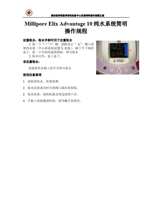
定量取水:取水手柄可用于定量取水
1. 按一下“-”“+”键,面板显示“ L”,键入需
要的水量(中心将系统设置为0.1L),摘下手下端的
盖子,按一下中间的量筒图标,即可取水
2. 取水完毕,盖上盖子。
非定量取水:
直接使用水桶上的开关即可取水
使用注意事项
1.请按需取水,拒绝浪费;
2.取水结束请及时关闭阀门或结束按钮;
3.取水结束,请将机器及周边清理干净。
4.手柄上的按键请轻按,请勿戴手套使用。
Valeport SWiFT CTD多参数声速测深仪说明书

DATA SHEETProduct DetailsMULTI-PARAMETERCTDSOUND SPEEDSWiFT CTDCTD ProfilerDesigned from the outset with the intention of a seamless workflow, the SWiFT CTD profiler provides survey-grade sensor technology coupled with the convenience of Bluetooth connectivity and rechargeable batteries. An integral GPS module, to geo-locate each profile, completes the package. Data can be easily and quickly downloaded and reviewed wirelessly, via Bluetooth, using Valeport’s new O cean software for Windows and Connect Pathway Edition for iO S and Android and instantly shared, in industry standard data formats through email and cloud services. A USB Cable and Bluetooth adapter are provided. In addition to the directly measured Conductivity, Temperature and Depth measurements, Salinity, Density and Sound Velocity is calculated using the UNESCO international standard algorithm and Chen and Millero equation.With an operational battery life of up to 5 days and the convenience of OCEAN & CONNECT PATHWAY EDITIONSOFTWAREDatasheet Reference: SWiFT CTD | May 2021As part of our policy of continuing development, Valeport Ltd. reserve the right to alter at any time, withoutnotice, all prices, specifications, designs and conditions of sale of all equipment - Valeport Ltd © 2021MaterialsHousing - Titanium | Sensor Guard - Acetal |Temperature Sensor - Titanium | Pressure Sensor - Titanium |Conductivity Sensor - Polyurethane coated titanium with ceramic core Depth Rating 500mDimensions ø78mm x Length 350mm Weight2.7kg (in air) / 1.65kg (in water)0660049-50SWiFT CTD ProfilerTitanium housing rated to 500mSupplied withPC Bluetooth adapterUSB interface and charging cable 1.5 A charger Valeport Ocean software Operating manual System transit caseBattery indicator GPS StatusBluetooth commsOperationalstatus。
gms106说明书
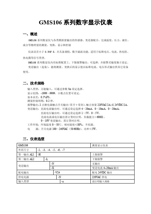
GMS106系列数字显示仪表一、概述GMS106系列数显仪与各类模拟量输出的传感器、变送器配合,完成温度、压力、液位、成分等物理量的测量、变换、显示和控制仪表误差小于0.5%F.S,并具备调校、数字滤波功能,适用于标准电压、电流、热电阻、热电偶等信号类型。
GMS106系列数显仪内有标准配置上、下限报警输出,可选择,并报警灵敏度独立设定。
变送输出(选装),能将测量、变换后的显示值以标准电流、电压形式输出供其它设备使用。
二、技术规格输入类型:万能输入,可通过参数Sn设定选择。
显示范围:-1999~9999,小数点位置可设定。
基本误差:0.5%FS。
测量控制周期:0.2秒。
报警输出:2点继电器触点开关输出(常开+常闭),触点容量220V AC/2A或24VDC/2A。
变送输出:直流电流输出时,可通过设定选择4~20mA,0~10mA,0~20mA;直流电压输出时,可通过设定选择1~5V,0~5V;直流电流或电压输出需订货时注明,负载能力>600Ω;0~10V变送输出,需订货时注明。
工作环境:环境温度0~50℃,相对湿度≤80%,不结露。
电源:开关电源100~240V AC(50/60Hz),功率≤5W。
三、仪表选型四、仪表接线1、-1型仪表接线图2、-3、-4、-5型仪表接线图3、-6型仪表接线图3、-6型仪表接线图五、操作说明(1) 参数设置说明仪表的每个参数在第六节《参数速查表》中列出。
oA1控制参数AH、AL是否受密码控制oA1设置为OFF时,不受密码控制;设置为ON时,若未设置密码,虽然可以进入、修改,但不能存入。
进入参数设置状态后,若1分钟以上无按键操作,仪表将自动退出设置状态。
(2) 报警设定值的设置方法①按住设置键“SET”2秒以上不松开,进入设置状态,仪表显示AH②单次按下“SET”键可以顺序选择本组其它参数③按移位键调出当前参数的原设定值,闪烁位为修正位④通过移位键移动修改位,加键增值、减键减值,将参数修改为需要的值⑤按“SET”键存入修改好的参数,自动转到下一参数。
Model106操作手册

Model 106自容式/直读式测流计安装& 8008 CDU操作手册VALEPORT LIMITED2013年5月目录Model 106 (1)自容式/直读式测流计 (1)安装& 8008 CDU操作手册 (1)1 简介 (3)1.1 一般描述 (3)2 系统描述 (3)2.1 设备 (3)2.2 甲板单元 (4)2.3 提供的设备 (4)2.4 客户供应 (4)3 安装 (4)3.1 机械安装 (4)3.2 电路连接 (5)3.3 串行数据格式 (6)3.4 电池 (6)4 USING 8008 CDU操作 (6)4.1 操作流程 (7)4.2 CDU记录的有关注意事项 (9)4.3 DATA REPLAY (9)4.4 外部连接 (9)4.5 打印机输出 (10)4.6 存储容量 (10)5 维护 (11)5.1 更换电池 (11)5.2 8008 CDU 电池更换 (11)5.3 螺旋桨 (12)5.4 一般说明 (12)5.5 O型圈尺寸 (12)5.6 备份锂电池 (13)6 校准 (13)附录 1 指标(见彩页) (13)附录 2 图解 (14)附录 3 接线图 (16)附录 4 发货前检查列表 (18)1 简介本手册涵盖了106型自容式/直读式测流计和8008显示控制单元配合使用的安装和操作手册。
手册还涵盖了一般维护程序、设备校准数据。
测流计和软件的操作包含在补充的DataLog软件手册中。
1.1 一般描述106型是基于螺旋桨式测量流速和流向的海流计,可选温度和深度参数传感器。
标准配置是自容式,可以选配直读式配置。
两种设备都可以通过电脑直接操作;还可以用8008控制显示单元控制直读:自容式:可以通过连接电脑和内置9路D型插头的甲板电缆设置采样和提取数据。
自容式测流计布放时不可能控制或从其读取数据。
直读式:RS232通讯可以通过外接4路Mil-Spec插头和电脑的短线(最大50m) 读取数据。
EPI流量计说明书
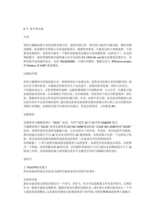
A节简介和安装介绍你的主触摸流量计包括流量传感元件,温度传感元件,桥式放大器/信号输出板,微处理器电路板,变送器外壳和探头支持或流量部分。
根据您的要求,可能是这些个别集成到一个流量变送器组件,或者你可能有一个额外的流量变送器信号处理器组装(远程电子)。
在这两种配置中,微处理器转换非线性输入信号从线性0-5 VDC4-20 mA输出流量变送器信号。
各种其他可选的通信协议,包括RS232/RS485,火线红外模块,数据记录与EPICommunicator 和Modbus或HART兼容模块。
仪器的开箱你的主触摸热式质量流量计是一种精密的电子流量仪表。
虽然这些流量计是坚固耐用的,他们应在交货时检查,以确保没有损害发生于运送途中。
如果经检查发现,损害已经发生,立即通知承运人,并把货物损坏索赔。
运输容器或箱子应谨慎处理,小心打开,以避免可能造成的损害的内容。
后容器被打开的内容,应仔细清除,并检查各个部分对照装箱单。
请注意,装箱清单会显示所有选项为您的仪器订购。
许多,如果不是全部,这些选项将被纳入流仪表本身并不会是单独的组件。
最后验证检查设备校准范围如流量计的文档上显示匹配你的采购订单规格。
如果您发现不符或有任何疑问,你是怎样领受,立即联系EPI。
电源要求电源要求主触摸流量计“DC24”选项,为用户提供18至24伏特DC@250毫安。
主触摸流量计“AC115”选项电源要求115 VAC,50/60赫兹标准,或220 VAC,50/60赫兹“AC230”选项。
如果管道是用来括电源输入线,它应该适合于该应用,导电性,和内连接外壳接地。
我们的建议电线尺寸为18佐治亚州的所有AC搁浅接线。
如果流量计包括一个远程电子组装,然后流量变送器电源提供连接到远程组件(见G部分对应的接线说明你的配置)。
十英尺的两导线连接电缆提供与远程组件。
如果更多的电缆是必需的,应替换为一个两线,双绞屏蔽电缆10'的长度。
在回路的导线的尺寸应不超过5欧姆电阻不小于22特设工作组。
多普勒流量计使用说明书(单、便)

KAD 系列便携多普勒流量计~单声道在线多普勒流量计使 用 说 明 书(触摸屏)^MC量 制 00000251号目录…第一章概述----------------------------------2第二章性能参数------------------------------6第三章外形及安装尺寸------------------------6第四章传感器的安装--------------------------7第五章主机安装------------------------------10第六章按键与显示----------------------------11第七章功能/参数窗口详解---------------------12第八章一般故障及排除方法--------------------12、,;第一章概述1-1简要说明KAD系列在线超声多普勒流量计是一种根据多普勒方法进行测量的超声波流量计,它适用于测量含有大量杂质的液体和浆体。
既可以在管道外部测量液体的流量,也可以采用插入式传感器进行测量,用户可以根据现场条件选择传感器安装方式。
管外测量时无需对管道进行破损和改造。
安装和拆卸十分方便,为您省去了一笔可观的安装和拆卸费用,并且可使您的工艺不间断,这样也就将因仪表安装而造成停产的损失降到了最低。
但是管外安装时传感器必须定期维护。
而插入式测量稳定性可靠性更好,如果在条件允许情况下,采用插入式测量更为稳妥。
KAD在线超声多普勒流量计采用先进的单片机技术和超大规模集成电路,使其高度智能化,极大地提高了运行的稳定性,从而保证了仪表的精度和可靠性。
仪表的外壳采用进口全塑机箱,达到国际IP65的防护等级。
KAD在线超声多普勒流量计适用于城市污水处理厂、环保监测及矿山、油田、冶金、化工、炼油、造纸、食品等行业的城市排水、工业废水、生活污水、泥浆、纸浆、油水混合液等流量计量。
适用于钢铁、硬质塑料管等硬质管材,可以对多种管径和壁厚的管内含有悬浮固体颗粒或气泡的二相流体进行测量。
在线便携式水分仪
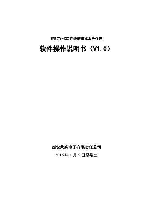
WPR(T)-1XX在线便携式水分仪表软件操作说明书(V1.0)西安荣森电子有限责任公司2016年1月5日星期二0、注意事项................................................................................................................................ - 3 -1、按键说明................................................................................................................................ - 4 -2、操作显示................................................................................................................................ - 4 -2.1显示主界面................................................................................................................... - 4 -2.2、密码界面.................................................................................................................... - 5 -2.3、主要功能菜单............................................................................................................ - 6 -3、详细操作指导........................................................................................................................ - 7 -3.1、 Calibration//标定子菜单.................................................................................... - 7 -3.1.1 Apend items //新增表格或者新增标定点.............................................. - 7 -3.1.2 Modify items //修改标定点...................................................................... - 9 -3.1.3 Delete items ,//删除表定点.................................................................. - 10 -3.1.4 Parameters.................................................................................................... - 11 -3.1.5 Calc. method //计算方式........................................................................ - 12 -3.2、System info //系统信息 ........................................................................................... - 12 -3.3、Comm. set //端口设置 ............................................................................................. - 13 -3.3.1、ComPort choose.......................................................................................... - 13 -3.3.2、Baudrate set.............................................................................................. - 13 -3.3.3、Slave ID get.............................................................................................. - 13 -3.4参数设置菜单............................................................................................................. - 14 -3.5时间设置菜单............................................................................................................. - 14 -3.6标定表切换................................................................................................................. - 14 -3.7背光灯开、关或自动开关......................................................................................... - 15 -4、其他...................................................................................................................................... - 15 -0、注意事项注意事项说明:当使用分离式显示仪器时,与传感器的物理连接都应在断电情况下进行,否则会烧坏对应的RS232或RS485硬件接口。
- 1、下载文档前请自行甄别文档内容的完整性,平台不提供额外的编辑、内容补充、找答案等附加服务。
- 2、"仅部分预览"的文档,不可在线预览部分如存在完整性等问题,可反馈申请退款(可完整预览的文档不适用该条件!)。
- 3、如文档侵犯您的权益,请联系客服反馈,我们会尽快为您处理(人工客服工作时间:9:00-18:30)。
3.1、清洗.......................................................................................................... 8 3.2、电池更换................................................................................................... 8
5
上海精导科学仪器有限公司 Shanghai P-NAV Scientific Instruments, Co.,Ltd. E-mail:sales@
2.3、记录模式设置(Mode)
记录模式 直读 记录 直读及自容方式
Mode工作模式设置 Dir直读方式,仪器实时将测量数据输出给电脑来显示 Log记录模式,仪器将测量数据记录在内存中,而不把数据传给电脑来显示 Dir & Log 直读和记录模式,测量数据同时记录在内存和传输给电脑
3. 入水测量 仪器设置完毕后,便可以进行测量工作。仪器尾部带有入水开关,入水后自动开 启。
4. 清水冲洗 测量完毕后,应用清水冲洗仪器,因海水中含有盐分、泥沙等,如不及时清洗, 日积月累会对仪器产生损害。
5. 数据下载
数据下载为文本文件,可用 Excel 等文本编辑工具打开进行相应处理,提取需要的数据。
4.2、内存
系统带 512k 内存,可存储 8000 组流速流向数据,若也同时采集温度及压力数据, 可记录 4000 组数据。
4.3、螺丝
如果仪器上螺丝丢失,请用 M3 x 6 型钛金属的螺丝更换,如果采用其他材料的螺丝, 产生 galvanic 腐蚀的可能性很大,会破换仪器钛金属外壳的外观甚至密封性。
2
上海精导科学仪器有限公司 Shanghai P-NAV Scientific Instruments, Co.,Ltd. E-mail:sales@
二、仪器设置
若流速非常低,如只有几个厘米/秒,则有必要设置多一点的平均处理时间,以提高 水流测量精度。
2.1、总菜单
文件 设置 显示 选项
三、日常维护
3.1、清洗
设备的外部组件都采用钛金属或聚合物材料做成,这些材料都具有防腐蚀性能。 螺旋桨及尾部传感器端应该保持清洁。每次使用后,用淡水清洗。
螺旋桨应该能够自由转动,可以将仪器竖直放,用手转动来测试它。建议卸下螺 旋桨进行清洗,已避免泥沙淤积的螺旋桨内部影响测量精度。 取下螺旋桨:
1) 轻轻转动卸下螺旋桨防护罩 2) 转动卸下螺旋桨前段的鼻子(黄色) 3) 取下转轴上的两个螺帽 4) 将螺旋桨从转轴上卸下 清洗: 清洗螺旋桨及转轴上的泥沙残渣
窗口 关于
设置 Setup
Port 端口设置 Connect 连接 Run 运行 Stop 停止
显示 Display
Brief 简明数据显示窗口 Full 全数据显示窗口 Scroll 数据列表窗口 Graph 时序图 ScatterPLot 流速流向分布图
3
上海精导科学仪器有限公司 Shanghai P-NAV Scientific Instruments, Co.,Ltd.
窗口 Window
Cascade 层叠 Tile 平铺
2.2、取样模式设置(Sample setup)
Model106水流仪的取样模式只有基于时间TIME这一种模式。仪器最还采样周期为1 秒,用户可以在Sample Period(采样周期)设定。如该值为10,则表示每10秒采集 一次。
取样设置
取样周期 每多少秒取样一次
10Leabharlann 2.5、其他设置信息设备信息 内存:总量/空余 设备时间: 电池电压: 固化软件版本:
波特率设置 波特率默认为 4800,建议不要修 改
7
上海精导科学仪器有限公司 Shanghai P-NAV Scientific Instruments, Co.,Ltd. E-mail:sales@
6
上海精导科学仪器有限公司 Shanghai P-NAV Scientific Instruments, Co.,Ltd. E-mail:sales@
2.4、数据下载 Logged data
数据下载 Logged data 下载 Extract 清除文件 Clear Files
Valeport Model106 螺旋桨式水流仪 简明操作手册
2008 年 10 月
上海精导科学仪器有限公司
Shanghai P-NAV Scientific Instruments, Co.,Ltd 地址:上海市北渔路 28 弄长宁馥邦 8 号 1202 室 电话:021-32525022、29050682 传真:021-52177887 邮箱:sales@ 网址:
1
上海精导科学仪器有限公司 Shanghai P-NAV Scientific Instruments, Co.,Ltd. E-mail:sales@
一、一般操作步骤
1. 仪器连接 如图所示,将 Y 电缆一端与仪器数据端口想连,另一端 RS232 串口与电脑串口 相连
2. 仪器设置 如需要对仪器当前的设置进行修改,则需要连接仪器,对采样周期及平均数等进 行处理。了解仪器工作是否正常、内存使用及电池电量等基本情况。
平均数 设定多少个取样 值平均计算后记 录
设置 取消 时间设置 取样模式
传感器出厂参数设置
平均数 Averaging period 如设定6,表示取6个采样数计算平均后记录一个值。如果采样周期设定为10秒一次, 那么仪器每记录一个数需要60秒即一分钟时间。 备注:记录和显示的数据为平均值,所以如果您需要记录每个一个采样值,则将平均 数设定为1.
2.1、总菜单 ...................................................................................................... 3 2.2、取样模式设置(Sample setup)............................................................... 5 2.3、记录模式设置(Mode) ........................................................................... 6 2.4、数据下载 Logged data ............................................................................. 7 2.5、其他设置信息............................................................................................ 7
四、注意事项 .......................................................................................10
4.1、电池........................................................................................................ 10 4.2、内存........................................................................................................ 10 4.3、螺丝........................................................................................................ 10
0
上海精导科学仪器有限公司 Shanghai P-NAV Scientific Instruments, Co.,Ltd. E-mail:sales@
目录
一、一般操作步骤..................................................................................2 二、仪器设置 .........................................................................................3
3.2、电池更换
1) 将电缆插头与悬挂支架中间的 4 个螺丝旋出
8
上海精导科学仪器有限公司 Shanghai P-NAV Scientific Instruments, Co.,Ltd. E-mail:sales@
2) 将两节轻轻脱开,将电池仓拖出来
3) 将旧电池取出,把新电池装进去
Brief 简明数据显示窗口
E-mail:sales@
Full 全数据窗口
Scroll 列表窗口 Graph 时序图 Scatter Plot 流速流向分布图
4
上海精导科学仪器有限公司 Shanghai P-NAV Scientific Instruments, Co.,Ltd. E-mail:sales@
9
上海精导科学仪器有限公司 Shanghai P-NAV Scientific Instruments, Co.,Ltd. E-mail:sales@
四、注意事项
4.1、电池
当采用内部 1.5V 一号碱性电池供电时,在 10 秒一次的取样频率下,可使用 30 天, 5 分钟一次的采样频率,可连续使用 56 天。采用 3.6 伏一号锂电池,10 秒采样率下, 可使用 90 天,5 分钟采样率下,可使用 180 天。 如以实时(直读)方式工作时,因 RS232 数据通讯模块会消耗电流,所以若采用内 部电池供电,电池的使用时间会缩短,建议采用外部供电,外部供电电源范围是 12-30VDC,电流在 40 毫安左右。Y 电缆的红色线为正极,黑色为负极。
