3030RGB红绿蓝黄橙紫贴片灯珠规格书
格天光电3030LED规格书

Normalized Luminous Flux
Angular Displacement(degrees) 角位移 (degrees)
VF
Test Condition 测试条件
IF=150mA
Criteria For Judging Damage 判定标准
Initial Data ± 10% 初始 值± 10%
Reverse Current
IR
反向电流
VR=5V
IR≤ 10μA
Luminous Flux
φv
IF=150mA
Average φv degradation ≤20%
禁止反向驱动
Notes 注释:
. Tolerance of Luminous Flux is ± 3%. 光通量的公差为± 3%。 2. Tolerance of Forward Voltage is ± 0.1V. 正向电压的公差为±
0.1V 。
第 4/9 页
White Bining Information 白光分 BIN 图
◆Portable lighting and Reading lighting 手提灯和台灯
◆Traffic signaling 交通信号灯
Table of Contents 目录
Product Nomenclature Outline Dimensions 尺寸说明 -----------------------------------------------------------------------------3
格天光电3030LED规格书

Reverse Voltage 反向电压
Symbol / 符号 IF Tj Topr Tstg ~ ~
Value / 数值 150 115 -40~+60 0~+60 ±2,000V HBM -5
5.Electrical Characteristics Curve 电性特征曲线图(Tj = 25˚C)
5-1.White,Royal Blue , Blue, Green 白光、深蓝光、蓝光、绿光
5-2. Amber, Red 黄光、红光
正
正
向
向
电
电
流
流
Forward Current (mA)
Forward Current (mA)
IFP
1000
Unit / 单位 mA ℃ ℃ ℃ ~ mV/℃
mA
VR
Not designed for reverse operation
禁止反向驱动
Notes 注释: . Tolerance of Luminous Flux is ±3%. 光通量的公差为±3%。 2. Tolerance of Forward Voltage is ±0.1V. 正向电压的公差为±0.1V。
第 3/9 页
Parameters 参数
Electrical-Optical Characteristics at IF=150mA,Ta=25℃ 光电特性 IF=150mA Ta=25℃
Parameter 参数 Luminous Flux / 光通量 Correlated Color Temperature 相关色温 CRI / 显色指数 Forward Voltage / 正向电压 Power Dissipation / 耗散功率 View Angle / 发光角度 Thermal Resistance / 热阻
SMD 0603红黄绿双色LED灯珠规格书

承认书SPECIFICATION FOR APPROVAL 客户Customer:客户品号Customer P/N:鑫光硕品号Xgs Model:规格Specification:XGS-PB1615UEAG-04SMD0603红黄绿双色20MA制作Prepared By:李忠审核Checked By:Customer Confirmation客户确认采购部Pur Dept By品质部QA Dept By工程部E ng Dept By深圳市鑫光硕科技有限公司SHEN ZHEN XIN GUANG SHUO TECHNOLOGY CO.,LTD 公司地址:广东省深圳市宝安区沙井万丰村前路31号8楼一厂地址:广东省深圳市龙岗区嶂背创业二路18-1号二厂地址:广东省东莞市石排镇庙边王村沙迳工业区·Customer:Technical Data SheetPN:XGS-PB1615URAG-04For:IF=20mAContents1.Features2.Applications3.Package dimensions4.Absolute maximum rating5.Electrical optical characteristics6.BIN range7.Package label8.Soldering pad dimensions9.Soldering conditions10.Package tape specifications11.Typical electro-optical characteristics curves12.Reliability test items and conditions13.Cautions14.NoteCustomer confirm Approved by Checked by Issued byPart No.XGS-PB1615UEAG-04Emitted Color Super Red Super Green Len's Color Water Clear Chip Material AlGaInP AlGaInP----◆Features:Compatible with automatic placement equipmentCompatible with reflow solder processLow power consumption and wide viewing angleThis product doesn’t contain restriction Substance,comply ROHS standard.◆Applications:Automotive and TelecommunicationFlat backlight for LCD,switch and symbol in telephone and faxGeneral use for indicators◆Package Dimensions:Electrodes:Au PlatingEncapsulating Resin:Epoxy ResinPackage:BT Resin◆Absolute Maximum Rating (Ta=25℃)Parameter Symbol Value Unit UE AG Power Dissipation P D 6060mW Pulse Forward Current I FP 100mA DCForward CurrentI F 20mA Reverse Voltage V R 5V Operating Temperature Range Topr -40℃~85℃℃Storage Temperature RangeTstg-40℃~100℃℃I FP condition:pulse width ≤1ms ,duty cycle ≤1/10◆Electrical Optical Characteristics (Ta=25℃)Notes:1.Tolerance of Luminous Intensity ±10%2.Tolerance of Dominant Wavelength ±2nm3.Tolerance of Forward Voltage ±0.05V4.Luminous Intensity is measured by xgs’s equipment on bare chipsParameter Symbol Min Typ.Max.Unit Test Condition Luminous Intensity I V Red 60100--mcd I F =20mA Green 2035--Forward Voltage VF Red 1.8-- 2.4V I F =20mA Green 1.8-- 2.4Reverse Current IR Red ----10uA V R =5V Green ----10Dominant Wavelength λd Red 616--628nm I F =20mA Green 566--576Viewing Angle2θ1/2Red --140--Deg.I F =20mAGreen --140--◆BIN rangeLuminous intensity(tolerance is±10%@If=20mA/chip):BIN CODE Min.(mcd)Max.(mcd)UE K6080 L80100 M100130 N130160AG F2027 G2735 H3545 J4560Dominant Wavelength(tolerance is±2nm@If=20mA/chip):BIN CODE Min.(nm)Max.(nm)UE D616619 E619622 F622625 G625628AG H566568 J568570 K570572 L572574 M574576Forward voltage(tolerance is±0.05V@If=20mA/chip):BIN CODE Min.(V)Max.(V)UE AG F 1.8 1.9G 1.9 2.0H 2.0 2.1 J 2.1 2.2 K 2.2 2.3 L 2.3 2.40.92.63℃/sec.260℃Max.10sec.Max.210℃Pre-heating 120~160℃3℃/sec.-4℃/sec.60~120sec.120se .c.Max.◆Soldering Pad Dimensions:◆Soldering Conditions(Maximum allowable soldering conditions)Reflow soldering profile <Pb-free solder>Time•Reflow soldering should not be done more than two times.•Do not stress its resin while soldering.•After soldering,do not warp the circuit board.T e m p e r a t u r e1.50.5◆Package Tape Specifications:(3000pcs/Reel)◆Typical Electro-Optical Characteristics Curves:◆Reliability(1)Test Items and ConditionsNO Test Item Test Conditions Sample Ac/ Re1Temperature Cycle -40±5℃→25±5℃→100±5℃→25±5℃(30min,5min,30min,5min)100Cycles200/12High Temperature Storage Ta:100±5℃Test time=1000HRS(-24HRS,+72HRS)200/13High Temperature AndHigh Humidity WorkingTa:85±5℃,R H:85±5%,IF=20Test time=500HRS(-24HRS,+72HRS)200/14Low Temperature Storage Ta:-40±5℃Test time=1000HRS(-24HRS,+72HRS)200/15Operating Life Test Connect with a power IF=20mATa=Under room temperatureTest time=1000HRS(-24HRS,+72HRS)200/16Thermal Shock -40±5℃→100±5℃(15min,15min)100Cycles200/17IR-Reflow Pb-Free Process①80℃②100℃③120℃④160℃⑤170℃⑥235℃⑦270℃⑧255℃,60cm/min,2times200/1(2)Criteria of judging the damageItem Symbol Test condition Criteria for judgement Min.Max.Forward voltage VF IF=Test Current/U.S.L*1.1 Reverse current IR VR=5V/15uA LuminousintensityIV IF=Test Current L.S.L*0.7/ Wave lengthλD/λP IF=Test Current/U.S.L±2nm Appearance/View check No mechanical damage *U.S.L:Upper standard level L.S.L:Lower standard level◆Storage and application notices1.Storage1.Calculated shelf life in sealed bag:12months at<30℃and<90%relative humidity(RH)2.1TOP LED:After bag is opened,devices that will be subjected to reflow solder or other high temperature process must be:a)Mounted within:168hours of factory conditions≤30℃/60%RH,orb)Stored at ambient of<20%RH2.2CHIP LED:After bag is opened,devices that will be subjected to reflow solder or other high temperature process must be:a)Mounted within:one year of factory conditions≤30℃/60%RH,orb)Stored at ambient of<20%RH3.Device require bake,before mounting,if:a)Humidity indicator Card reads>10%when read at25±5℃b)Above conditions are not metBaking condition:24hours at60±3℃and<5%RH4.The internal and esterand boxes can not be contacted with ground to prevent absorption of moisture; 5.No acid,alkali,salt,corrosive and explosive gas;away from sunlight and keep the environment clean; 2.Application1.Do not use any unknown chemical liquid to clean LED,it will damage the LED resin surface;use the alcohol under the room temperature if necessary but less than1min,or use the ultrasonic cleaning with proper characters,such as correct power,frequency,etc;2.Do not touch the epoxy resin area when carrying LEDs by tweezers(as the following pictures), especially after the soldering process,the epoxy resin will turn to soft,the internal instruction will be damaged by the tweezers which cause the electric character’s failure;nozzle is recommended by using SMT mounting.Correct Incorrect3.Soldering iron:double-side soldering iron with power of less than25W;soldering temperature:less than 300℃;soldering time:less than3sec.;1time completed is recommended,if the2nd soldering process is requested,3mins must be left to ensure the high temperature status can return to room temperature;◆Cautions1、PackageWhen moisture is absorbed into the package it may vaporize and expand during soldering.There is a possibility that this can cause exfoliation of the contacts and damage to the optical characteristics of the LEDs. So the moisture proof package is used to keep moisture to a minimum in the package.2、StorageBefore opening the package:The LEDs should be kept at5~30°C and60%RH or less.The LEDs should be used within a year.After opening the package:The LED must be used within24hours,else should be kept at5~30℃and30%RH or less.The LEDs should be used within7days after opening the package.If unused LEDs remain,they should be stored in moisture proof packages,recommended to return the LEDs to the original moisture proof bag and to reseal the moisture proof bag again.If the LEDs have exceeded the storage time,baking treatment should be performed more than 24hours at60±5°C.3、Soldering IronEach terminal is to the tip of soldering iron temperature less than300℃for3seconds within once inless than the soldering iron capacity25W.Leave two seconds and more internals,and do soldering of each terminal.Be careful because the damage of the product is often started at the time of the hand solder.4、RepairingRepairing should not be done after the LEDs have been soldered.When repairing is unavoidable,a double-head soldering iron should be used(as below figure).It should be confirmed beforehand whether the characteristics of the LEDs will or will not be damaged by repairing.5、The LED electrode sections are comprised of a gold plated.The gold surface may be affected by environments which contain corrosive gases and so on.Please avoid conditions which may cause the LED to corrode or discolor.This corrosion or discoloration may cause difficulty during soldering operations.It is recommended that the User use the LEDs as soon as possible.6、Please avoid rapid transitions in ambient temperature,especially in high humidity environments where condensation can occur.◆Notes:1、Above specification may be changed without notice.We will reserve authority on material change for above specification.2、When using this product,please observe the absolute maximum ratings and the instructions for the specification sheets.We assume no responsibility for any damage resulting from use of the product which does not comply with the instructions included in the specification sheets.。
贴片LED灯珠0603统佳0603翠绿规格书

TJ-1608RSWD-033
2010-3-10
Customer Approved
Checked
Prepared
Customer Service Hotline:400-676-8616
TEL:0769-8662 5999
E-MIAL∶tongjiacn@
1 / 10
FAX:0769-8200 2227
6 / 10
TAIWAN TONGJIA OPTOELECTRONICS TECHNOLOGY CO., LTD
DONGGUAN TONGJIA OPTOELECTRONICS TECHNOLOGY CO., LTD
Test items and results of reliability
Type
30℃⇔ 65℃ 90%RH 24hrs/1cycle
10 cycle
0/22
Environmental Sequence
High Temperature Storage
Ta=80℃
1000 hrs
0/22
Humidity Heat Storage
Ta=60℃ RH=90%
1000 hrs
0/22
Low Temperature Storage
DONGGUAN TONGJIA OPTOELECTRONICS TECHNOLOGY CO., LTD
Optical characteristic curves
Relative Intensity vs. Wavelength
Wavelength (nm) Forward Current vs. Forward Voltage
3.Number of reflow process shall be 2 times or less.
3030黑晶
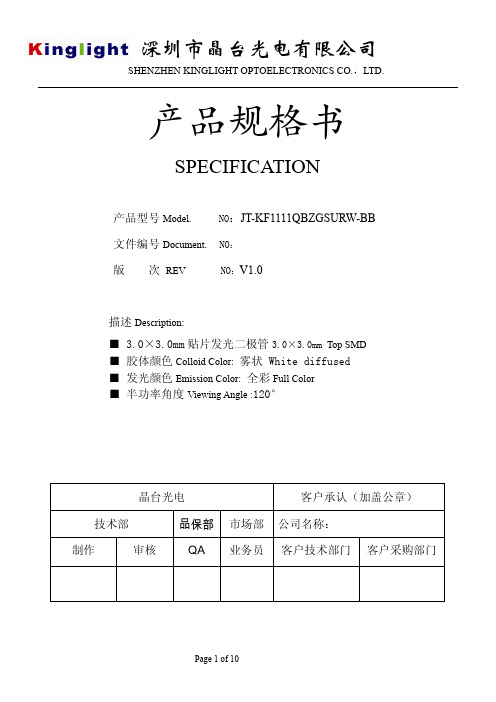
产品规格书SPECIFICATION产品型号Model. NO:JT-KF1111QBZGSURW-BB文件编号Document. NO:版次REV NO:V1.0描述Description:■ 3.0×3.0mm贴片发光二极管3.0×3.0mm Top SMD■ 胶体颜色Colloid Color: 雾状 White diffused■ 发光颜色Emission Color: 全彩Full Color■ 半功率角度Viewing Angle :120°晶台光电客户承认(加盖公章)技术部品保部市场部公司名称:制作审核 QA 业务员客户技术部门客户采购部门1. 外形尺寸D imensions单位(Units):毫米(mm)1423BuleGreen Red注意:所有尺寸单位为mm ,如无特殊说明误差范围为±0.05mmAll dimensions area in mm tolerance is ±0.05mm unless otherwise noted.2. 光电特性Electrical / Optical characteristics(1) 最大限度额定值Absolute Maximum Ratings (TA=25ºC)项目Item符号Symbol 最大绝对额定值Absolute Maximum Rating 单位 UnitBlue Green Red 正向电流Forward CurrentIF 30 30 50 mA 正向峰值电流Pulse Forward Current IFP 150150 195mA 反向电压Reverse Voltage VR 9 V 功率消耗Power Dissipation PD 350mW 工作温度Operating Temperature Topr -40ºC To +85ºC °C 贮藏温度Storage Temperature Tstg -40ºC To +85ºC°C 焊接温度Soldering Temperature TsldReflow Soldering: 260ºCHand Soldering : 350ºCfor 10sec.for 3sec.1/10周期, 0.1 msec 脉宽IFP Conditions : 1/10 Duty Cycle, 0.1 msec Pulse Width.(2) 本样品光电参数Initial Electrical/Optical Characteristics (TA=25ºC)正向电压允许误差± 0.05V Tolerance of measurement of Vf is ±0.05 V ..亮度允许误差±10% Luminous Intensity Measurement allowance is ± 10%. 波长允许误差±1nm Color Coordinates Measurement allowance is ± 1nm.符号Symbol项目 Item 单位Units发光颜色Device最小值Min.规格值Typ.最大值Max.测试条件 Test ConditionsVF正向电压 Forward Voltage VRed 1.8 2.3 IF =20mAGreen 2.83.4 IF =15mABlue 2.7 3.3 IF =10mAIR 反向电流 Reverse CurrentuA - - - 10 VR =9V Δλ1/2发光角度Viewing Angle º- - 120 - IF =3X20mA Iv发光强度 Luminous Intensity McdRed 110 148.5 IF =20mAGreen 150 202.5 IF =15mA Blue 40 54 IF =10mA λD主波长Dominate WavelengthNmRed 620 625 IF =20mAGreen 522.5 525 IF =15mA Blue 462.5465 IF =10mA(3)发光强度范围Luminous Intensity Ranking (TA=25ºC)亮度允许误差± 10%Luminous Intensity Measurement allowance is ± 10%.以上发光强度最小值和最大值参数仅供参考,但批量出货亮度分光跨度范围为1:1.35之内.Above are the reference for minimum and maximum of luminous intensity which rank in the rate of 1:1.35 in the process of light splitting when manufacturing massively.(4) 主波长范围Color Coordinates Ranking (TA=25ºC)波长允许误差±0.5nmColor Coordinates Measurement allowance is ± 0.5nm .以上波长最小值和最大值参数仅供参考,但批量出货波长分光跨度范围为R:5nm 、G:2.5nm 、B:2.5nm 之内 Above are the reference for minimum and maximum of wavelength, while it ranks as:R:5nm/G:2.5nm/B:2.5nm. when light splitting in mass manufacturing.项目 Item 发光颜色 符号 Symbol 测试条件 Test Conditions 最小值 Min. 最大值 Max. 单位Units发光强度Luminous Intensity R IvIF=20mA 110 148.5 Mcd G IvIF=15mA 150 202.5 Mcd B Iv IF=10mA 40 54 Mcd项目 Item发光颜色符号 Symbol测试条件 Test Conditions 最小值 Min.最大值 Max.单位 Units波长 Color CoordinatesR λD IF=20mA 620 625 nm G λD IF=15mA 522.5 525 nm BλDIF=10mA462.5 465 nm3.特性曲线Characteristic curve对亮度与波长之间的关系发光角度图解F O R W A R D C U R R E N T V s F O R W A R D V O L T AG E 正向电流与正向电压关系曲线图F O R W A R D C U R R E N T V s F O R W A R D V O L T A G E正向电流与正向电压关系曲线图亮度与环境温度关系曲线图正向电流递减曲线图亮度与正向电流关系曲线图正向电流与正向电压关系曲线图F O R W A R D C U R R E N T V s F O R W A R D V O L T A G E4.可靠性RELIABILITY(1)测试项目及结果Test Items and Results序号Items 试验项目Test Item试验条件Standard Test Method试验设备Equipment型号Type试验能力Experiment capacity参考标准Reference1温度循环Temperature Cycle-40℃~25℃~100℃~25℃30分钟5分钟 30分钟5分钟30 mins 5 mins30 mins5mins恒温箱thermostat/温度:-50℃-150℃Temperature: -50℃-150℃JEITA ED-4701100 1052冷热冲击Thermal Shock-40℃~100℃15分钟15分钟15mins 15 mins恒温箱thermostat/温度:-50℃-150℃Temperature: -50℃-150℃MIL-STD-202G3高温储存High TemperatureStorageTa=100℃恒温箱thermostat/温度:-50℃-150℃Temperature: -50℃-150℃JEITA ED-4701200 2014低温储存Low TemperatureStorageTa=-40℃恒温箱thermostat/温度:-50℃-150℃Temperature: -50℃-150℃JEITA ED-4701200 2025 常温寿命试验Steady StateOperating LifeTa=25℃老化架Aging rack/ /6 高温高湿寿命试验Steady StateOperating Life ofHigh Humidity &TemperatureTa=60℃ RH=90%IF=20mA(R,G,Y)/15mA(W,B)高温试验箱high-temperature test chamber/ /空气加湿器airhumidifier/ /空气湿度表airhygrometer/ /7 可焊性(回流焊)Soderability (ReflowSodering)Tsol=235℃±5℃,使用助焊剂With soldering flux回流焊焊机ReflowSolderingMachine/ /JEITA ED-4701300 3038 耐焊性(回流焊)Resistance toSolderingHeat(ReflowSoldering)Tsol=260℃,10秒回流焊焊机ReflowSolderingMachine/ /JEITAED-47013003015.注意事项Cautions(1) 焊接条件Soldering Conditions本产品最多只可回焊两次,且在首次回焊后须冷却至室温之后方可进行第二次回焊.Number of reflow process shall be less than 2 times and cooling process to normal temperature is required between first and Second soldering process. 推荐焊接条件(Recommended soldering conditions)有铅回焊 (Lead Solder )无铅回焊 (Lead-Free Solder)回流焊接Reflow Soldering手工焊接预热温度 Pre-heat 预热时间 Pre-heat time 峰值温度 Peak temperature 焊接时间 Soldering time 条件Condition有铅 Lead Solder 无铅Lead-free Solder温度 Temperature焊接时间 Soldering time 350°C Max.3 sec. Max.(one time only)120 ~ 150°C 120 sec. Max. 230°C Max. 10 sec. Max. 参考下图180 ~ 200°C 120 sec. Max. 260°C Max. 10 sec. Max. 参考下图推荐焊盘式样(Recommended Soldering Pattern) 单位:毫米( Units:mm)(2)静电 Static Electricity触摸LED时,推荐使用防静电手腕带或防静电手套.It is recommended that a wrist band or an anti-electrostatic glove be used when handling the LEDs.所有装置、设备、机器均应接地.All devices, equipment and machinery must be properly grounded.静电损坏的LED会显示出异常特征:正向电压变低或在低电流时死灯.标准: I F=0.5mA时, V F > 2.0V Damaged LEDs will show some unusual characteristics such as the forward voltage becomes lower, or the LEDs do not light at the low current. Criteria : (V F> 2.0V at I F=0.5mA)(3)防潮包装Moisture Proof Package使用防潮包装It is recommended that moisture proof package be used .(4)使用注意事项Cautions:4.1.在开包装之前,请先检查包装袋有无漏气,如果有漏气现象,请退回我司重新烘烤除湿包装后再使用。
红光贴片LED-侧贴红光贴片LED灯珠规格书参数

承认书SPECIFICATION FOR APPROVAL 客户Customer:客户品号Customer P/N:鑫光硕品号Xgs Model:规格Specification :XGS-PB0802UE-02SMD 0805侧面红光普亮 20MA制作Prepared By:李忠审核Checked By:Customer Confirmation 客户确认采购部Pur Dept By品质部QA Dept By工程部Eng Dept By深圳市鑫光硕科技有限公司SHEN ZHEN XIN GUANG SHUO TECHNOLOGY CO.,LTD公司地址:广东省深圳市宝安区沙井万丰村前路31号8楼一厂地址:广东省深圳市龙岗区嶂背创业二路18-1号二厂地址:广东省东莞市石排镇庙边王村沙迳工业区Tel:Website :HData Sheet PN: XGS-PB0802UE-02 For:IF=20mAContents3.P ackage dimensions4.A bsolute maximum ratingoptical characteristics rangelabel pad dimensionsconditions10.Package tape specifications11.T ypical electro-optical characteristics curvestest items and conditions14.NotePart No.XGS-PB0802UE-02Emitted Color High Super Red Len's Color Water Clear Chip Material AlGaInP----◆Features:Compatible with automatic placementequipment Compatible with reflow solderprocessLow power consumption and wide viewing angleThis product doesn’t contain restriction Substance, comply ROHS standard.◆Applications:Automotive and TelecommunicationFlat backlight for LCD ,switch and symbol in telephone and faxGeneral use for indicators◆Package Dimensions:Unit:mmElectrodes: Ag Plating Tolerance±◆Absolute Maximum Rating (Ta=25℃)FP◆Electrical Optical Characteristics(Ta=25℃)Notes: of Luminous Intensity ±10%of Dominant Wavelength ±2nm3.Tolerance of Forward Voltage ±4.Luminous Intensity is measured by XGSLED’s equipment on bare chips3℃/sec.260℃ M ax. .210℃Pre-heating 120~160℃ 3℃/sec.-4℃/sec.60~120sec..◆ Soldering Pad Dimensions:◆ Soldering Conditions (Maximum allowable soldering conditions)Reflow soldering profile<Pb-free solder>Time• Reflow soldering should not be done more than two times. • Do not stress its resin while soldering.• After soldering,do not warp the circuit board.T e m p e r a t u r e225◆ Package Tape Specifications: ( 4000 pcs/Reel)Reel Lead No LEDs470225250603205 Reels in one Box 10 Boxes in one Carton◆ Typical Electro-Optical Characteristics Curves :Forward Current Vs Ambient Temperature5040302010200175 150 125107550 25 0 Forward Current Vs Relative Luminosity Ta=25℃2040608010010 20 30 40 50Ambient Temperature Ta (° C)Forward Current (mA)20015010050 Relative Luminosity VsAmbient TemperatureIf=15mA-50° -60°-70°-80°-90°-40°-30°-20°-10°0°10°20°30°40°50°60°70°80°90°0 020406080100Radiation AngleAmbient Temperature Ta (° C)R e l a t i v e L u m i n o s i t y (%)F o r w a r d C u r r e n t (m A )R e l a t i v e L u m i n o s i t y (%)◆Reliability(1)Test Items and Conditions(2)C riteria of judging the damage* Upper standard level Lower standard leve◆Cautions1、PackageWhen moisture is absorbed into the package it may vaporize and expand during soldering. There is apossibility that this can cause exfoliation of the contacts and damage to the optical characteristics of the LEDs. So the moisture proof package is used to keep moisture to a minimum in the package.2、StorageBefore opening the package: The LEDs should be kept at 5~30°C and 60%RH or less. The LEDs should be used within a year.After opening the package: The LED must be used within 24 hours, else should be kept at 5~30℃and 30% RH or less. The LEDs should be used within 7days after opening the package. If unused LEDs remain, they should be stored in moisture proof packages, recommended to return the LEDs to the original moisture proof bag and to reseal the moisture proof bag again.If the LEDs have exceeded the storage time, baking treatment should be performed more than 24hours at 60±5°C.3、Soldering IronEach terminal is to the tip of soldering iron temperature less than 300℃ for 3 seconds within once inless than the soldering iron capacity 25 two seconds and more internals, and do soldering of each terminal. Be careful because the damage of the product is often started at the time of the hand solder.4、RepairingRepairing should not be done after the LEDs have been soldered. When repairing is unavoidable, a double-head soldering iron should be used (as below figure). It should be confirmed beforehand whether thecharacteristics of the LEDs will or will not be damaged by repairing.5、The LED electrode sections are comprised of a gold plated. The gold surface may be affected by environments which contain corrosive gases and so on. Please avoid conditions which may cause the LED to corrode or discolor. This corrosion or discoloration may cause difficulty during soldering operations. It is recommended that the User use the LEDs as soon as possible.6、Please avoid rapid transitions in ambient temperature, especially in high humidity environmentswhere condensation can occur.◆Notes:1、Above specification may be changed without notice. We will reserve authority on material change for above specification.2 、 When using this product, please observe the absolute maximum ratings and the instructions for the specification sheets. We assume no responsibility for any damage resulting from use of the product which does not comply with the instructions included in the specification sheets.。
0603贴片灯珠规格书,0603红灯,蓝灯,黄绿,绿规格书
Package Dimensions
Hale Waihona Puke Notes: 1. All dimensions are in millimeters (inches). 2. Tolerance is .1(0.004") unless otherwise noted. 3.Specifications are subject to change without notice.
Note:
1. 1/10 Duty Cycle, 0.1ms Pulse Width.
SPEC NO: CJ568 APPROVED: Jun. Lu
REV NO: V.1 CHECKED:GEN.ZHANG
DATE: MAR/20/2006 DRAWN: Y.X.Y
PAGE: 1 OF 4
Hyper Red
300 250 200 150
Temoerature
S S
230°C Max 230°C
C Max
C/S Max C/S Max
100 50 25 0
C/S Max
0
50
100
Time
150
200
250
300
NOTES: 1. We recommend the reflow temperature 245°c(±5) The maximum soldering temperature shold be limited to 260°c 2. Don't cause stess too the epoxy resin while it is exposed to high temperature. 3. Numbe of reflow process shall be 2 time or less.
首尔LED灯珠最新说明
◆ Test condition : H2S 15ppm (25℃ / 75%), 504hrs
Product
no
Ave
5630C
Min
Max
Ave
5630D-E3
Min
Max
Ave
3030B-E2
Min
Max
Ave
3030C
Min
Max
Initial
Iv [cd]
15.98 15.56 16.17 13.06 12.86 13.29 13.33 13.28 13.43 12.50 11.51 12.77
Copyright ⓒ Seoul Semiconductor Co., Ltd.
204 lm/W (37.2lm)
207 lm/W (37.7lm)
Now
< 6>
2019.2Q
2019.3Q
2019.4Q
3030 3V Roadmap
@ Tj=25℃ / 65mA / 5000K / Ra80
240 MP or ES Under development
3528-3V (2PD-S1)
170
190
210
Lm/W
@5000K, CRI Min.80, Tj=25 °C 230
Copyright ⓒ Seoul Semiconductor Co., Ltd.
< 2>
Product Summary - 3030 Series
3V 3030
6V 3030
504hr
Po
10.36 10.07 10.70 11.84 11.58 12.24 11.09 10.97 11.19 12.40 11.42 12.67
红蓝双色贴片式发光二极管产品名称:0404-T0.4 XL-1010SURUBC 型号:XL-101

产品承认书产品名称:0404-T0.4红蓝双色贴片式发光二极管产品型号:XL-1010SURUBC客户名称:客户料号:承认日期:深圳市成兴光电子科技有限公司制定审核核准客户承认栏确认审核核准一、产品描述:●外观尺寸(L/W/H): 1.0x1.0x0.4mm●颜色:红蓝双色●胶体:透明胶体●EIA规范标准包装●环保产品,符合ROHS要求●适用于自动贴片机●适用于红外线回流焊制程二、外形尺寸及建议焊盘尺寸:备注:1.2.单位公差:毫米(mm):如无特别标注则为±0.10mm三、建议焊接温度曲线:有铅制程无铅制程四、最大绝对额定值(Ta=25℃):参数符号最大额定值单位消耗功率Pd 红55mW 蓝80最大脉冲电流(1/10占空比,0.1ms脉宽)I FP红100mA蓝100正向直流工作电流I F 红25mA 蓝25反向电压V R 红5V 蓝5工作环境温度Topr-30°C~+85°C 存储环境温度Tstg-40°C~+90°C焊接条件Tsol 回流焊:260°C,10s 手动焊:300°C,3s抗静电能力ESD2000V五、光电参数(Ta=25℃):参数符号颜色最小值代表值最大值单位测试条件光强IV 红42/59mcd IF=20mA 蓝40/68半光强视角2θ1/2//120/deg IF=20mA主波长λD 红619/624nm IF=20mA 蓝463/472正向电压VF 红 1.9/ 2.1V IF=20mA 蓝 2.6/ 3.2反向电流IR 红//1uA VR=5V 蓝//1备注:1.发光强度是由光纤和过滤器的组合测定的,因此接近视觉感应曲线;2.半光强视角是轴向发光强度一半时的离轴角;3.主波长λd源自CIE色度图,代表单一的波长,它定义了器件的颜色。
亮度分档:电压分档:波长分档:颜色代码最小值最大值单位测试条件红L224259mcd IF =20mA 蓝L324052mcdIF =20mAL335268颜色代码最小值最大值单位测试条件红F3 1.9 2.1VIF =20mA蓝I5 2.6 2.8VIF =20mAI6 2.8 3.0I73.03.2颜色代码最小值最大值单位测试条件红R22619624nm IF =20mA 蓝B11463466nmIF =20mAB12466469B13469472六、光电参数代表值特征曲线:φ60七、标签标识:CAT:光强(mcd)HUE:波长(nm)REF:电压(V)误差范围a.Luminous Intensity:±15%b.HUE:±1nmc.Forward Voltage:±0.1V八、包装载带与圆盘尺寸:φ13.0备注:1.尺寸单位为毫米(mm);2.尺寸公差如无标注,为±0.15mm;九、圆盘及载带卷出方向及空穴规格:尾端空壳载带的组合开始端空壳载带的组合盖带与空壳载带的组合十、内包装及外包装:内标签圆盘干燥剂防潮防静电袋5cartons/box外标签抽真空、热封10bags/carton至少160mm盖带和装有零件部分至少160mm盖带和至少160mm独立盖带或十一、信赖性实验:测试项目测试条件测试次数参考标准失效判定标准失效LED 数量(PCS )防潮等级1.回流焊最高温度=260℃,10秒,2次回流焊;2.回流焊之前存储条件:30℃,相对湿度=70%,168H;-JEITAED-4701300.301﹟10/22焊接信赖性(无铅回流焊)回流焊最高温度=245±5℃,5秒(无铅回流焊)-JEITAED-4701303303A ﹟20/22冷热循环-40℃30分钟~25℃5分钟~100℃30分钟~25℃5分钟300个循环JESD22-A104﹟10/22冷热冲击-35℃15分钟转换时间3分钟85℃15分钟300个循环JESD22-A106﹟10/22高温存储Ta=100℃1000小时JESD22-A103﹟10/22低温存储Ta=-40℃1000小时JESD22-A119﹟10/22常温老化Ta=25℃IF=20mA1000小时JESD22-A108﹟10/22(2)失效标准★U.S.L :规格上限L.S.L :规格下限标准﹟项目测试条件失效标准﹟1正向电压(V F )I F =20mA >U.S.L*1.1光强(IV )I F =20mA <L.S.L*0.7反向电流(I R )V R =5V >U.S.L*2.0﹟2焊接可靠性/锡膏覆盖焊盘比例小于95%十二、使用注意事项:◆使用:1.过高的温度会影响LED的亮度以及其他性能,所以为使LED有较好的性能表现,应将LED远离热源。
拓展-0603红黄双色led贴片灯珠规格书,参数
Operation Sequence
(2)CRITERIA FOR JUDGING THE DAMAGE
Item
Forward Voltage Reverse Current Luminous Intensity
Symbol
VF IR IV
Test Conditions
IF=10mA VR=5V IF=10mA
ATTENTION
OBSERVE PRECAUTIONS
ELECTROSTATIC SENSITIVE DEVICES
核准:
业务: 段小姐
工程:
日期: 2012-08-05
客户名称:
合 格 不合格
原因:
联系人:
客户确认:
ADD:深圳市宝安区西乡宝田一路拓展工业区 TEL:0755-29632541 FAX:0755-61528625 http://www.tzled.net
Reliability
(1)TEST ITEMS AND RESULTS
SMD LED
Environmental Sequence
Type
Test Item
Resistance to Soldering Heat(Reflow Soldering)
Temperature Cycle
Thermal Shock
Parameter
Test Condition Symbol
Wavelength at peak emission Spectral Half bandwidth Forward voltage Dominant wavelength Luminous intensity Viewing angle at 50% Iv Reverse current
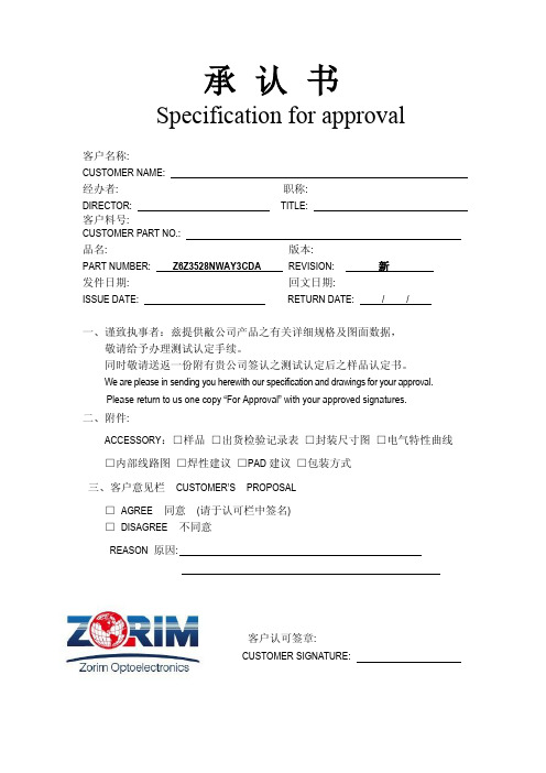
3030RGB红绿蓝黄橙紫贴片灯珠规格书
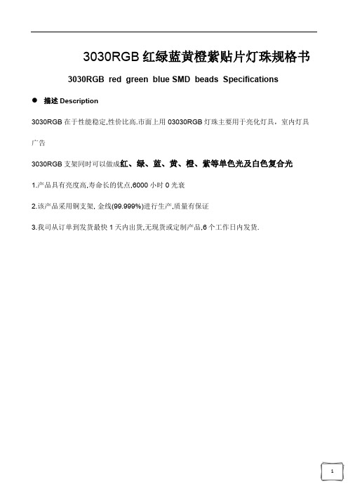
3030RGB红绿蓝黄橙紫贴片灯珠规格书3030RGB red green blue SMD beads Specifications
描述Description
3030RGB在于性能稳定,性价比高.市面上用03030RGB灯珠主要用于亮化灯具,室内灯具广告
3030RGB支架同时可以做成红、绿、蓝、黄、橙、紫等单色光及白色复合光
1.产品具有亮度高,寿命长的优点,6000小时0光衰
2.该产品采用铜支架, 金线(99.999%)进行生产,质量有保证
3.我司从订单到发货最快1天内出货,无现货或定制产品,6个工作日内发货.
CUSTOMER SIGNATURE:
(Units : mm)
静电 Static Electricity
触摸 LED 时,推荐使用防静电手腕带或防静电手套.
It is recommended that a wrist band or an anti-electrostatic glove be used when handling the LEDs.
所有装置、设备、机器均应接地.
All devices, equipment and machinery must be properly grounded.
正向电压变低或在低电流时死灯.标准: IF=0.5mA 时, VF >
2.0V Damaged LEDs will show some unusual characteristics such as the forward voltage becomes
lower, or the LEDs do not light at the low current. Criteria : (VF > 2.0V at IF=0.5mA)。
台湾AOT灯珠产品规格书3020系列
Symbol IF IFP VR Tj Topr Tstg
ESD PD Tsld
Maximum Value
Unit
30
mA
100
mA
5
V
125
°C
-30 ~ +85
°C
-40 ~ +100
°C
±2000
V
105
mW
Reflow Soldering 260℃,10sec
CD0WW0000-AG00/AG01
Soldering Reflow
-Soldering of the SMD LEDs should conform to the soldering condition in the individual specifications. -SMD LEDs are designed for Reflow Soldering. -In the reflow soldering, too high temperature and too large temperature gradient such as rapid
Wavelength λ (nm)
90 o
0
CD0WW0000-AG00/AG01
Page 7 of 15
Preliminary
Recommended Reflow Soldering Conditions
Surface Mounting Condition
In automatic mounting of the SMD LEDs on printed circuit boards, any bending, expanding and pulling forces or shock against the SMD LEDs should be kept min. to prevent them from electrical failures and mechanical damages of the devices.
1206LED灯珠-SMD1206橙黄绿贴片LED-1206发光二极管规格书
C ustomer:·Technical Data SheetPN: XGS-PB3216AMAG-04For: IF=20mAContents1.Features2.Applications3.P ackage dimensions4.A bsolute maximum rating5.Electrical optical characteristics6.BIN range7.Package label8.Soldering pad dimensions9.Soldering conditions10.Package tape specifications11.T ypical electro-optical characteristics curves12.Reliability test items and conditions13.Cautions14.Note◆F eatures:Compatible with automatic placement equipmentCompatible with reflow solder processLow power consumption and wide viewing angleThis product doesn’t contain restriction Substance, comply ROHS standard.◆A pplications:Automotive and TelecommunicationFlat backlight for LCD ,switch and symbol in telephone and faxGeneral use for indicators◆P ackage Dimensions:Electrodes: Au PlatingEncapsulating Resin: Epoxy ResinPackage: BT ResinPage 1 of 8◆A bsolute Maximum Rating (Ta=25℃)I FP condition: pulse width ≤1ms ,duty cycle ≤1/10◆Electrical Optical Characteristics(Ta=25℃)2.Tolerance of Dominant Wavelength ±2nm3.Tolerance of Forward Voltage ±0.05V4.Luminous Intensity is measured by XGS’s equipment on bare chips◆ S oldering Pad Dimensions:◆ S oldering Conditions(Maximum allowable soldering conditions)Reflow soldering profile<Pb-free solder>• Reflow soldering should not be done more than two times. • Do not stress its resin while soldering.• After soldering,do not warp the circuit board.T e m p e r a t u r eFeeding D irection◆ Package Tape Specifications: (4000 pcs/Reel) Feeding,DirectionDimensions of Reel ( Unit:mm)Dimensions of Tape (Unit:mm)Arrangement of Tape(Unit:mm)AA4 32 1◆Typical Electro-Optical Characteristics Curves :Relative Luminous Intensity Vs.WavelenghtForward Current Vs.ForwardVoltage755025Ta=25°CTa=25°C0 540560 580 600 620Wavelenght(nm) 1.01.52.02.53.03.5Forward Voltage(V)R e l a t i v e L u m i n o u s I n t e n s i t y (%)F o r w a r d C u r r e n t (m A )◆R eliability(1)Test Items and Conditions(2)C riteria of judging the damage◆C autions1、PackageWhen moisture is absorbed into the package it may vaporize and expand during soldering. There is apossibility that this can cause exfoliation of the contacts and damage to the optical characteristics of the LEDs. So the moisture proof package is used to keep moisture to a minimum in the package.2、StorageBefore opening the package: The LEDs should be kept at 5~30°C and 60%RH or less. The LEDs should be used within a year.After opening the package: The LED must be used within 24 hours, else should be kept at 5~30℃and 30% RH or less. The LEDs should be used within 7days after opening the package. If unused LEDs remain, they should be stored in moisture proof packages, recommended to return the LEDs to the original moisture proof bag and to reseal the moisture proof bag again.If the LEDs have exceeded the storage time, baking treatment should be performed more than 24hours at 60±5°C.3、Soldering IronEach terminal is to the tip of soldering iron temperature less than 300℃ for 3 seconds within once inless than the soldering iron capacity 25 W.Leave two seconds and more internals, and do soldering of each terminal. Be careful because the damage of the product is often started at the time of the hand solder.4、RepairingRepairing should not be done after the LEDs have been soldered. When repairing is unavoidable, a double-head soldering iron should be used (as below figure). It should be confirmed beforehand whether the characteristics of the LEDs will or will not be damaged by repairing.5、The LED electrode sections are comprised of a gold plated. The gold surface may be affected by environments which contain corrosive gases and so on. Please avoid conditions which may cause the LED to corrode or discolor. This corrosion or discoloration may cause difficulty during soldering operations. It is recommended that the User use the LEDs as soon as possible.6、Please avoid rapid transitions in ambient temperature, especially in high humidity environments where condensation can occur.◆Notes:1、Above specification may be changed without notice. We will reserve authority on material change for above specification.2 、When using this product, please observe the absolute maximum ratings and the instructions for the specification sheets. We assume no responsibility for any damage resulting from use of the product which does not comply with the instructions included in the specification sheets.。
Cree J Series 3030 LED数据表说明书

J Series ® Products are sold exclusively by Cree Venture LED Company Limited (“Cree Venture”), regardless of geography. Any orders for J Series Products that are submitted to Cree LED or any of its other subsidiaries will be directed to Cree Venture for acknowledgment and order fulfillment.J Series ® 3030 LEDsPRODUCT DESCRIPTIONJ Series ® LEDs extend Cree LED’s industry-leading portfolio of lighting-class LEDs to a broader set of applications. The J Series 3030 Standard LEDs combine high efficacy and excellent value in a reliable package. The J Series 3030 Standard LEDs are optimized for applications where high efficacy and smooth appearance are critical, such as troffers, panel and outdoor area lights.FEATURES• Industry-compatible size : 3.0 x 3.0 x 0.5 mm • 3-V and 6-V configurations• Flux binned at 25 °C, chromaticity binned at 85 °C • 6500 K–2200 K ANSI CCTs available• 70, 80 & 90 CRI minmum available at 6500 K–2700 K • 80 CRI minmum available at 2200 K • RoHS and REACH compliant• UL ®recognized component (E495478)3030TABLE OF CONTENTSOrder Code & Bin Code Formats (3)Characteristics - JB3030 3-V Standard P Class (4)Operating Limits - JB3030 3-V Standard P Class (4)Flux Characteristics, Order Codes and Bins - JB3030 3-V Standard P Class (5)Relative Luminous Flux vs. Current - JB3030 3-V Standard P Class (6)Electrical Characteristics - JB3030 3-V Standard P Class (6)Relative Chromaticity vs. Current - JB3030 3-V Standard P Class (7)Relative Chromaticity vs. Temperature - JB3030 3-V Standard P Class (7)Characteristics - JK3030 3-V Standard P Class (8)Operating Limits - JK3030 3-V Standard P Class (8)Flux Characteristics, Order Codes and Bins - JK3030 3-V Standard P Class (9)Relative Luminous Flux vs. Current - JK3030 3-V Standard P Class (10)Electrical Characteristics - JK3030 3-V Standard P Class (10)Relative Chromaticity vs. Current - JK3030 3-V Standard P Class (11)Relative Chromaticity vs. Temperature - JK3030 3-V Standard P Class (11)Characteristics - JK3030 6-V Standard P Class (12)Operating Limits - JK3030 6-V Standard P Class (12)Flux Characteristics, Order Codes and Bins - JK3030 6-V Standard P Class (13)Relative Luminous Flux vs. Current - JK3030 6-V Standard P Class (14)Electrical Characteristics - JK3030 6-V Standard P Class (14)Relative Chromaticity vs. Current - JK3030 6-V Standard P Class (15)Relative Chromaticity vs. Temperature - JK3030 6-V Standard P Class (15)Relative Spectral Power Distribution (16)Relative Luminous Flux vs. Junction Temperature (17)Typical Spatial Distribution (17)Performance Groups - Luminous Flux (18)Performance Groups - Forward Voltage (19)Performance Groups - Chromaticity (20)Reflow Soldering Characteristics (29)Notes (30)Mechanical Dimensions (32)Tape & Reel (33)Packaging (34)CHARACTERISTICS - JB3030 3-V STANDARD P CLASSOPERATING LIMITS - JB3030 3-V STANDARD P CLASSThe maximum forward current is determined by the thermal resistance between the LED junction and ambient.Notes:• Cree Venture maintains a tolerance of ±7% on flux and power measurements, ±0.005 on chromaticity (CCx, CCy) measurements and ±2 on CRI measurements. See the Measurements section (page 30).• Cree Venture J Series 3030 LED order codes specify only a minimum flux bin and not a maximum. Cree Venture may ship reels in flux bins higher than the minimum specified by the order code without advance notice. Shipments will always adhere to the chromaticity restrictions specified by the order code.*Flux values @ 85 °C are calculated and for reference only.**Contact your Cree sales representative for kitted 3-step order code details.FLUX CHARACTERISTICS, ORDER CODES AND BINS - JB3030 3-V STANDARD P CLASS (I F = 65 mA, T j = 25 °C)The following table provides order codes for J Series JB3030 3-V Standard P Class LEDs. For a complete description of the order code nomenclature, please see the Order Code and Bin Code Formats section (page 3). For definitions of the chromaticity kits, please seethe Performance Groups - Chromaticity section (page 20).ELECTRICAL CHARACTERISTICS - JB3030 3-V STANDARD P CLASSRELATIVE CHROMATICITY VS. CURRENT - JB3030 3-V STANDARD P CLASSRELATIVE CHROMATICITY VS. TEMPERATURE - JB3030 3-V STANDARD P CLASSCHARACTERISTICS - JK3030 3-V STANDARD P CLASSOPERATING LIMITS - JK3030 3-V STANDARD P CLASSThe maximum forward current is determined by the thermal resistance between the LED junction and ambient.Notes:• Cree Venture maintains a tolerance of ±7% on flux and power measurements, ±0.005 on chromaticity (CCx, CCy) measurements and ±2 on CRI measurements. See the Measurements section (page 30).• Cree Venture J Series 3030 LED order codes specify only a minimum flux bin and not a maximum. Cree Venture may ship reels in flux bins higher than the minimum specified by the order code without advance notice. Shipments will always adhere to the chromaticity restrictions specified by the order code.*Flux values @ 85 °C are calculated and for reference only.**Contact your Cree sales representative for kitted 3-step order code details.FLUX CHARACTERISTICS, ORDER CODES AND BINS - JK3030 3-V STANDARD P CLASS (I F = 350 mA, T j = 25 °C)The following table provides order codes for J Series JK3030 3-V Standard P Class LEDs. For a complete description of the order code nomenclature, please see the Order Code and Bin Code Formats section (page 3). For definitions of the chromaticity kits, please seethe Performance Groups - Chromaticity section (page 20).RELATIVE LUMINOUS FLUX VS. CURRENT - JK3030 3-V STANDARD P CLASSELECTRICAL CHARACTERISTICS - JK3030 3-V STANDARD P CLASSRELATIVE CHROMATICITY VS. CURRENT - JK3030 3-V STANDARD P CLASSRELATIVE CHROMATICITY VS. TEMPERATURE - JK3030 3-V STANDARD P CLASSCHARACTERISTICS - JK3030 6-V STANDARD P CLASSOPERATING LIMITS - JK3030 6-V STANDARD P CLASSOperating LimitsThe maximum forward current is determined by the thermal resistance between the LED junction and ambient.Notes:• Cree Venture maintains a tolerance of ±7% on flux and power measurements, ±0.005 on chromaticity (CCx, CCy) measurements and ±2 on CRI measurements. See the Measurements section (page 30).• Cree Venture J Series 3030 LED order codes specify only a minimum flux bin and not a maximum. Cree Venture may ship reels in flux bins higher than the minimum specified by the order code without advance notice. Shipments will always adhere to the chromaticity restrictions specified by the order code.*Flux values @ 85 °C are calculated and for reference only.**Contact your Cree sales representative for kitted 3-step order code details.FLUX CHARACTERISTICS, ORDER CODES AND BINS - JK3030 6-V STANDARD P CLASS (I F = 150 mA, T j = 25 °C)The following table provides order codes for J Series JK3030 6-V Standard P Class LEDs. For a complete description of the order code nomenclature, please see the Order Code and Bin Code Formats section (page 3). For definitions of the chromaticity kits, please seethe Performance Groups - Chromaticity section (page 20).RELATIVE LUMINOUS FLUX VS. CURRENT - JK3030 6-V STANDARD P CLASSELECTRICAL CHARACTERISTICS - JK3030 6-V STANDARD P CLASSRELATIVE CHROMATICITY VS. CURRENT - JK3030 6-V STANDARD P CLASSRELATIVE CHROMATICITY VS. TEMPERATURE - JK3030 6-V STANDARD P CLASSRELATIVE SPECTRAL POWER DISTRIBUTIONRELATIVE LUMINOUS FLUX VS. JUNCTION TEMPERATURETYPICAL SPATIAL DISTRIBUTIONPERFORMANCE GROUPS - LUMINOUS FLUX (T= 25 °C)jJ Series JB3030 3-V Standard P Class LEDs are tested for luminous flux at 65 mA and placed into one of the following luminous-flux groups.J Series JK3030 3-V Standard P Class LEDs are tested for luminous flux at 350 mA. J Series JK3030 6-V Standard P Class LEDs are tested for luminous flux at 150 mA. Both are placed into one of the following luminous-flux groups.PERFORMANCE GROUPS - FORWARD VOLTAGE (T= 25 °C)jJ Series 3030 Standard P Class LEDs are tested for forward voltage and placed into one of the following voltage bins.The following voltage bins are indicated in the Forward Voltage Bin field in the bin code for JB3030 3-V Standard P Class LEDs.The following voltage bins are indicated in the Forward Voltage Bin field in the bin code for JK3030 3-V Standard P Class LEDs.The following voltage bins are indicated in the Forward Voltage Bin field in the bin code for JK3030 6-V Standard P Class LEDs.PERFORMANCE GROUPS - CHROMATICITY (T= 85 °C)jJ Series 3030 Standard P Class LEDs are tested for chromaticity and placed into one of the regions defined by the following bounding coordinates.PERFORMANCE GROUPS - CHROMATICITY - CONTINUED (T= 85 °C)PERFORMANCE GROUPS - CHROMATICITY - CONTINUED (T= 85 °C)jPERFORMANCE GROUPS - CHROMATICITY - CONTINUED (T= 85 °C)jPERFORMANCE GROUPS - CHROMATICITY - CONTINUED (T= 85 °C)jPERFORMANCE GROUPS - CHROMATICITY - CONTINUED (T= 85 °C)jREFLOW SOLDERING CHARACTERISTICSIn testing, Cree Venture has found J Series 3030 Standard P Class LEDs to be compatible with JEDEC J-STD-020C, using the parameters listed below. As a general guideline, Cree Venture recommends that users follow the recommended soldering profile provided by the manufacturer of the solder paste used, and therefore it is the lamp or luminaire manufacturer’s responsibility to determine applicable soldering requirements.Note that this general guideline may not apply to all PCB designs and configurations of reflow soldering equipment.Note: All temperatures refer to the topside of the package, measured on the package body surface.TTT e m p e r a t u r eNOTESMeasurementsThe luminous flux, radiant power, chromaticity, forward voltage and CRI measurements in this document are binning specifications only and solely represent product measurements as of the date of shipment. These measurements will change over time based on a number of factors that are not within Cree Venture’s control and are not intended or provided as operational specifications for the products. Calculated values are provided for informational purposes only and are not intended or provided as specifications.Pre-Release Qualification TestingPlease read the J Series Reliability Overview for the details of the pre-release qualification testing for J Series LEDs.Lumen MaintenanceCree Venture uses standardized IES LM-80-08 and TM-21-11 methods for collecting long-term data and extrapolating LED lumen maintenance. For information on the specific LM-80 data sets available for this LED, refer to the public J Series LM-80 results document.Please read the Thermal Management application note for details on how thermal design, ambient temperature, and drive current affect the LED junction temperature.Moisture SensitivityCree Venture recommends keeping J Series 3030 Standard P Class LEDs in the provided, resealable moisture-barrier packaging (MBP) until immediately prior to soldering. Unopened MBP that contains J Series 3030 Standard P Class LEDs does not need special storage for moisture sensitivity.Once the MBP is opened, J Series 3030 Standard P Class LEDs should Array be handled and stored as MSL 3 per JEDEC J-STD-033, meaning theyhave limited exposure time before damage to the LED may occur duringthe soldering operation. The table on the right specifies the maximumexposure time in days depending on temperature and humidity conditions.LEDs with exposure time longer than the specified maximums must bebaked according to the baking conditions listed below.Baking ConditionsIt is not necessary to bake all J Series 3030 Standard P Class LEDs. Only the LEDs that meet all of the following criteria must be baked:1. LEDs that have been removed from the original MBP.2. LEDs that have been exposed to a humid environment longer than listed in the Moisture Sensitivity section above.3. LEDs that have not been soldered.LEDs should be baked at 60 ºC for 24 hours. LEDs may be baked in the original reels. Remove LEDs from the MBP before baking. Do not bake parts at temperatures higher than 60 ºC. This baking operation resets the exposure time as defined in the Moisture Sensitivity section above.3030NOTES - CONTINUEDRoHS ComplianceThe levels of RoHS restricted materials in this product are below the maximum concentration values (also referred to as the threshold limits) permitted for such substances, or are used in an exempted application, in accordance with EU Directive 2011/65/EC (RoHS2), as implemented January 2, 2013. RoHS Declarations for this product can be obtained from your Cree Venture representative or from the Product Ecology section of the Cree LED website.REACH ComplianceREACH substances of very high concern (SVHCs) information is available for this product. Since the European Chemical Agency (ECHA) has published notice of their intent to frequently revise the SVHC listing for the foreseeable future, please contact a Cree representative to insure you get the most up-to-date REACH SVHC Declaration. REACH banned substance information (REACH Article 67) is also available upon request.UL® Recognized ComponentThis product meets the requirements to be considered a UL Recognized Component with Level 4 enclosure consideration. The LED package or a portion thereof has been investigated as a fire and electrical enclosure per ANSI/UL 8750.Vision AdvisoryWARNING: Do not look at an exposed lamp in operation. Eye injury can result. For more information about LEDs and eye safety, please refer to the J Series LED Eye Safety application note.J SERIES ® 3030 LEDMECHANICAL DIMENSIONSThermal vias, if present, are not shown on these drawings.All measurements are ±0.2 mm unless otherwise indicated.All measurements are ±0.1 mm unless otherwise indicated.MarkSideCathodeCathodeAnode Anode0.13.0Ø2.60.690.21.4282.120.482.20.523.00.15Tie Bars2.40 1.600.600.300.500.400.801.90 1.300.55Recommended Solder PadRecommended Stencil Pattern (Shaded Area Is Open)TAPE & REELAll Cree Venture carrier tapes conform to EIA-481D, Automated Component Handling Systems Standard.All dimensions in mm.User feed directionCathode sideAnode sideCapacity per reel 5,000 LEDsLeader More than 400 mm unloaded tapeTrailer More than 160 mm unloaded tapeØ 13 mmØ 165.1 mm (6.5 inch)Carrier tapeUpper bandUser feed directionPACKAGING Unpackaged ReelPackaged ReelLabel with Cree VentureOrder Code, Lot Number,Quantity, Product ParametersDesiccant BagVacuum-Sealed Bag Humidity CardLabel with Cree Venture OrderCode, Lot Number, Quantity,Product ParametersPACKAGING - CONTINUEDJ Series 3030 Standard P Class LEDs are packaged in boxes for shipment. Box sizes and the number of reels per box are as follows.Each box has at least one label (shown as a white square in the diagrams below) showing the order code, lot number, quantity, and product parameters.Box 1Box 2Box 3Box 4。
贴片发光二极管参数大全

贴片发光二极管参数大全LED 贴片常见灯珠规格型号和参数0603、0805、1210、3528、5050 都是指 LED 灯带上常使用的发光元器件 ----LED 的尺寸大小(英制 / 公制)叫法,例如 0603 指的是长度为 0.06 英寸,宽度为 0.03 英寸。
但是要注意 3528 和 5050 单位是公制。
下面是这些规格的详细介绍:0603:换算为公制是 1608,即表示 LED 元件的长度是 1.6mm,宽度是 0.8mm。
行业简称 1608,英制叫法是 0603。
0805:换算为公制是 2012,即表示 LED 元件的长度是 2.0mm,宽度是 1.2mm. 行业简称 2112,英制叫法是 0805。
1210:换算为公制是 3528,即表示 LED 元件的长度是 3.5mm,宽度是 2.8mm。
行业简称 3528,英制叫法是 1210。
3528:这是公制叫法,即表示LED 元件的长度是3.5mm,宽度是 2.8mm。
行业简称 3528。
5050:这是公制叫法,即表示LED 元件的长度是5.0mm,宽度是 5.0mm。
行业简称 5050。
目前大多数厂商生产的贴片型灯条采用的都以 3528 和 5050 以及3535 和 5630 的居多,也有很多把 3528 和 5050 和 3535 等贴片 led 用在汽车照明上的。
更多的贴片led 详细规格,或者产品规格书等请咨询统佳的客服人员索取。
3528 20mA 3.0-3.6v 0.06w3014 30mA 3.2-3.6v 0.1w4014 30mA 3.2-3.6v 0.1w5050 60mA 3.2-3.6v 0.18w5630 150mA 3.2-3.6v 0.5w大功率 350ma 3.2-3.6v 1W、3528(0.06W)、3629(0.2-0.3W)、5050(0.2-0.5W)、5630(0.2-0.5W)、3014、3020(0.06W)首先 LED 光源分为小功率 LED 光源(直插式,SMD 贴片器件)大功率 LED 光源。
SG-3030_40爱普生kHz贴片晶体振荡器规格书
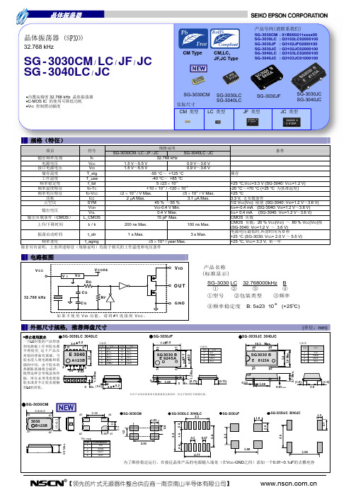
关于在目录内使用的记号
●无铅。 ●符合欧盟 RoHS 指令。 欧盟 RoHS 指令免检的含铅产品。 (密封玻璃、高温熔化性焊料或其他材料中包含铅。 ) ●为汽车方面的应用,如汽车多媒体、车身电子、遥控无钥门锁等。
●为汽车行驶安全方面的应用(引擎控制单元、气囊、电子稳定程序控制系统) 。
注意事项
·本材料如有变更,恕不另行通知。量产设计时请确认最新信息。 ·未经 Seiko Epson 公司书面授权,禁止以任何形式或任何方式复制或者发布本材料中任何部分的信息内容。 ·本材料中的书面信息、应用电路、编程、使用等内容仅供参考。Seiko Epson 公司对第三方专利或版权的侵权行为不负有任何责任。本材料 未对任何专利或知识版权的许可权进行授权。 ·本材料中规格表中的数值大小通过数值线上的大小关系表示。 ·当出口此材料中描述的产品或技术时,你应该遵守相应的出口管制法律和法规,并按照这些法律和法规的要求执行。 请不要将产品(以及任何情况下提供任何的技术信息)用于开发或制造大规模杀伤性武器或其他军事用途。还要求,不要将产品提供给任何 将产品用于此类违禁用途的第三方。 ·此类产品是基于在一般电子机械内使用而设计开发的,如将产品应用于需要极高可靠性的特定用途,必须实现得到弊公司的事前许可。若 无许可弊公司将不负任何责任。 1.太空设备(人造卫星、火箭等) 2.运输车辆机器控制装置(汽车、飞机、火车、船舶等) 3.用于维持生命的医疗器械 4.海底中转设备 5.发电站控制机器 6.防灾防盗装置 7.交通设备 8.其他,用于与 1~7 具有同等可靠性的用途。
裸存 +25 C,VCC=3.3 V (SG-3040: VCC=1.2 V) -20 C~+70 C (+25 C 为基准温度) +25 C 3.3 V, 无负载条件 1/2 VCC(VIO) 级别 (SG-3040: VIO=1.2 V~3.6 V) IOH=-0.4 mA (SG-3040: VIO=1.2 V~3.6 V) IOL= 0.4 mA (SG-3040: VIO=1.2 V~3.6 V) CMOS 负载 CMOS 负载:20 % VCC(VIO) ~ 80 % VCC(VIO)极 (SG-3040: VIO=1.2 V ~ 3.6 V) 电源电压最低时,所需时间为 0 秒 +25 C (SG-3030: VCC= 2.0 V~5.5 V) +25 C, VCC= 3.3 V, 第一年
3020贴片LED灯珠规格书

Test Item
Test Condition
Ta= Under Room Temperature As Per Data Sheet Maximum Rating
Reference Standard
1000HRS
24HRS,+72HRS)*@20mA (-
Reference Standard
IR-Reflow
Environmental
Temp. maintain above 183℃ 60-150 seconds Peak temperature range 235℃+5/-0 ℃ Time within 5°C of actual Peak Temperature (tp) 10-30 seconds Ramp-down rate +6 ℃/second max Ramp-up rate(217℃ to Peak) +3℃/ second max Temp. maintain at 175(±25)℃ 180 seconds max MIL-STD-750D:2031.2 J-STD-020C
2. Package Profile & Soldering PAD Suggested
Cathode Mark
①
②
①
Polarity
②
Soldering PAD Suggested:
Notes: 1. All dimensions are in millimeters ; 2. Tolerance is ± 0.10 mm unless otherwise noted.
9. Tape Leader & Trailer Dimensions And Reel
5050RGBW中文规格书
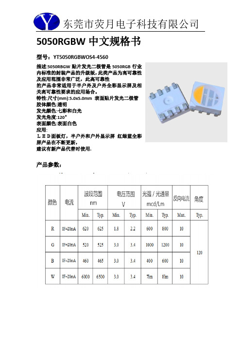
5050RGBW中文规格书型号:YT5050RGBWOS4-4560描述:5050RBGW贴片发光二极管是5050RGB行业内标准的封装产品的升级版,此类产品为高可靠性及应用范围非常广泛,此高可靠性的产品非常适用于半户外及户外全彩显示屏及相关高可靠性要求的应用场合。
特性:尺寸(mm):5.0x5.0mm 表面贴片发光二极管胶体颜色:透明发光颜色:七彩和白光发光角度:120°表面颜色:表面白色应用:LED面板灯,半户外和户外显示屏红绿蓝全彩屏产品在不断更新,建议有新产品代替时使用.产品参数:注意:所有尺寸单位为mm;如无特殊说明误差范围为±0.05mm 。
***应用注意事项特点本文件主要向顾客及用户介绍怎样如何更好的使用我司的SMD LED 产品。
描述一般来说,SMD 5050跟一般的半导体有相同的用法。
当使用荧月电子的SMD5050产品,请遵从以下的使用方法以保护SMD LED 产品。
1.清洁:不要使用不明化学液体清洗SMD LED,不明的化学液体可能会损坏SMDLED。
当必要清洗时,把SMD LED沉浸在酒精里,在正常的室温下少于1 分钟并且自然干燥15 分钟,然后才开始使用。
2.防潮湿包装为避免产品在运输及储存中吸湿,SMD LED 的包装是用防潮的铝包装袋包装,并且包装袋里面含有干燥剂及湿度卡,干燥剂主要起到控制包装袋里的湿度,湿度卡主要是起到监控包装袋里的湿度。
3.储存a.包装袋密封后贮存在条件为温度< 40℃,湿度< 60%RH,保存期为12 个月。
当超过保质期时,需要重新烘烤。
b.在开包装之前,请先检查包装袋有无漏气或湿度指示卡有无变色,如果有漏气或湿度指示卡有变色现象,请重新烘烤后再使用。
c.开封后请在以下条件使用:温度< 30℃、湿度在30%RH 以下;如果使用时间超出24小时,须做以下烘烤处理才可使用。
d.烘烤条件:产品在烘箱在温度为70℃±5℃;相对湿度≤10%RH,时间:24 小时。
- 1、下载文档前请自行甄别文档内容的完整性,平台不提供额外的编辑、内容补充、找答案等附加服务。
- 2、"仅部分预览"的文档,不可在线预览部分如存在完整性等问题,可反馈申请退款(可完整预览的文档不适用该条件!)。
- 3、如文档侵犯您的权益,请联系客服反馈,我们会尽快为您处理(人工客服工作时间:9:00-18:30)。
3030RGB红绿蓝黄橙紫贴片灯珠规格书3030RGB red green blue SMD beads Specifications
描述Description
3030RGB在于性能稳定,性价比高.市面上用03030RGB灯珠主要用于亮化灯具,室内灯具广告
3030RGB支架同时可以做成红、绿、蓝、黄、橙、紫等单色光及白色复合光
1.产品具有亮度高,寿命长的优点,6000小时0光衰
2.该产品采用铜支架, 金线(99.999%)进行生产,质量有保证
3.我司从订单到发货最快1天内出货,无现货或定制产品,6个工作日内发货.
CUSTOMER SIGNATURE:
(Units : mm)
静电 Static Electricity
触摸 LED 时,推荐使用防静电手腕带或防静电手套.
It is recommended that a wrist band or an anti-electrostatic glove be used when handling the LEDs.
所有装置、设备、机器均应接地.
All devices, equipment and machinery must be properly grounded.
正向电压变低或在低电流时死灯.标准: IF=0.5mA 时, VF >
2.0V Damaged LEDs will show some unusual characteristics such as the forward voltage becomes
lower, or the LEDs do not light at the low current. Criteria : (VF > 2.0V at IF=0.5mA)。
