热流道操作方法
热流道系统的操作规范与保养_

Integrated Engineering Solution
四、产品演示
Integrated Engineering Solution
Open at 2.23s
Open at 0s
四、产品演示
Integrated Engineering Solution
五、热流道操作及注意事项
Integrated Engineering Solution
制作
批
准
审核
核准
热流道系统的操作规范与保养
目录
热流道定义及结构 热流道优势和局限性
产品演 示 热流道操作及注意事项
热 流道保养
Integrated Engineering Solution
1 2 3 4 5
一、热流道定义及结构
Integrated Engineering Solution
热流道系统是指传输塑化物料进入模具型腔的一整套系统。 热流道系统的一般组成如下图所示:
五、热流道操作及注意事项
Integrated Engineering Solution
7)一旦发现有出胶不顺的现象,千万切记不要盲目开高温度,而是要查找不出胶的 真正原因,一般不出胶原因如下: a. 胶口堵塞 b. 阀针没有打开,流道口完全被碳化的料堵死
浇口 堵铁
(a-1)
浇口堵铜
(a-2)
(b-0)
二〉加热器的失效形式
Integrated Engineering Solution
三〉热电偶的工作原理
Integrated Engineering Solution
三〉热电偶的工作原理 热电偶的工作原理—示意图
Integrated Engineering Solution
GUNTHER 热通道系统 说明书
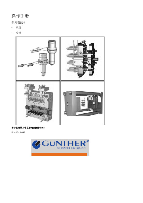
操作手册热流道技术• 系统• 喷嘴务必在开始工作之前阅读操作说明!务必在开始工作之前阅读操作说明!Doc-ID:6449©GONTHER HeiGkanatechnk GmbHSachsenberger StraGe 1D-35066 Frankenberg(Eder)电话:+49(0)6451 5008-0传真:+49(0)6451 5008-94电子邮箱:**************************网址:24.08.2009 V.1.02 热流道技术目录 3目录1 概述 (6)1.1 手册信息 (6)1.2 符号说明 (7)1.3 责任限制 (8)1.4 版权 (9)1.5 备件 (9)1.6 保修条款 (10)1.7 客户服务 (10)2 安全 (11)2.1 客户责任 (11)2.2 人员要求 (12)2.2.1 资格 (12)2.2.2 未经批准的人员 (13)2.2.3 培训 (13)2.3 正确使用 (14)2.4 个人防护设备 (15)2.5 特定危险 (16)2.6 安全设施 (18)2.7 固定以免开启 (19)2.8 在危险情况以及事故情形下的行为 (20)2.9 环境保护 (20)3 技术数据 (21)3.1 连接数值 (21)3.2 工作条件 (22)3.3 润滑剂 (22)3.4 型号牌(例示) (23)4 结构与功能 (24)4.1 热流道系统概述 (24)4.2 电力插座和热电偶连接 (26)4.2.1 电力插座-CMT-/热插头-CMLK- (26)4.2.2 电力插座-FKT-/热插头-CMLK- (27)5 运输、包装与储存 (28)5.1 有关运输的安全说明 (28)5.2 包装上的标志 (29)5.3 货运检查 (30)5.4 运输 (30)5.5 包装 (31)5.6 储存 (32)6 安装盒试运行 (33)6.1 安全 (33)6.2 准备工作 (34)6.2.1 检查前提条件 (34)6.2.2 所需工具 (35)热流道技术目录4 6.2.3 测量高度调节 (35)6.2.4 热膨胀伸缩缝K (36)6.3 安装 (38)6.3.1 “热半”组件 (38)6.3.2 组装带起模板机构的阀门浇口系统 (43)6.3.3 组装带起模板机构的阀门浇口系统 (44)6.3.4 安装针 (46)6.4 有关阀门浇口的说明 (47)6.5 试运行 (49)6.6 注释/说明 (53)6.6.1 浇口 (53)6.6.2 向斜面浇注 (55)6.6.3 通过中间浇口进行浇注 (55)6.6.4 在高光泽度可视表面上进行反向浇注 (56)7 运行 (57)7.1 安全 (57)7.2 开启 (57)7.3 关闭 (58)7.4 过程中断情况下所采取的行为 (58)7.5 变色 (59)7.6 紧急停车 (60)8 故障排查 (61)8.1 安全 (61)8.2 故障排查表格 (63)8.2.1 故障 (63)8.2.2 阀门浇口系统 (66)8.3 故障排除后启动 (67)9 维护 (68)9.1 安全 (68)9.2 维护计划 (70)9.3 维护任务 (71)9.3.1 清洁喷嘴 (71)9.3.2 在模具内测量喷嘴温度 (75)9.3.3 清洁阀针 (75)9.3.4 清洁歧管 (76)9.3.5 更换单点针阀上的O 型圈 (81)9.3.6 重新润滑滑动凸轮机构 (82)9.3.7 污物 (83)9.4 紧固转矩 (83)9.4.1 一般紧固转矩 (83)9.5 维护完成后进行测量 (84)10 拆卸 (85)10.1 安全 (85)10.2 拆卸针 (87)10.3 “热半”组件 (89)热流道技术目录 510.4 拆卸和处置 (91)11 备件列表 (92)12 附录 (93)12.1 技术信息 (94)12.2 高度调节/尺寸检查 (95)12.3 热流道系统检查表 (96)12.4 符合性声明 (98)13 索引 (99)热流道技术概述 61 概述1.1 手册信息本手册为有关热流道系统的安全和有效使用的说明。
热流道控制器用户使用说明书

热流道控制器用户使用说明书
步骤一:安装控制器。
→1、使用热流道系统可以改变由多个浇口产生的熔合线位置,从而改善产品的外观质量。
对于大型塑料制品,如电器外壳、汽车门板等,通常需要使用两个或更多的填充浇口才能填满产品。
→使用普通的热流道浇注系统,在注射成型时浇口同时进行填充。
产品需要改变熔接线位置时,只能通过热流道温控箱的温差改变熔体的流动速度实现熔接线位置的位移。
工艺调试复杂,产品质量难以保证,生产效率也会受到影响。
→使用时序控制器根据产品需求的熔接线位置,只需要调整浇口的开启时间关闭时间来改变熔体的流动位置而实现熔接线位置的位移。
虽然也需要花费时间调试,但是能保证长期稳定的生产,不会因热流道浇口温差而引起缺陷。
·方法二:可以独立控制浇口的注射量,从而调整产品的阴阳色、缺胶、毛边、烧焦等缺陷。
对于由两个浇口以上的热流道模具在注射成型时出现的毛边、某个筋位填充不满、烧焦等缺陷,通常需要使用多级注射的压力速度找位置调整缺陷。
但是,有时无法进行调试,只能通过修模处理缺陷问题。
使用时序控制器改变单个浇口的开启时间关闭时间,就可以实现产品缺陷的调整。
IDAQ-8000-24热流道温控箱用户手册

2、注意事项______
____ __
z 电源线应选择与机箱和负载容量相匹配的规格; z 连接电源线时,必须严格按照箱体上的接线提示操作; z 连接信号线时,注意与模具接线方式和感温线类型的匹配情况; z 接线完成后,检查连接是否正确并接触良好; z 通电前,请确认供电电源符合温控箱要求; z 控制器工作时,应确保机箱风扇处于工作状态和交流指示灯亮起; z 需要改变机箱接线或更换控制模块时,应依次关闭机箱上的开关 z 人机界面仅为控制模块 M1-M8 状态监控与参数设定使用; z 控制模块 M1-M8 可以扩展到 48 通道,本温控箱是 24 通道,用到控制模块 M1-M4;
地址:深圳市南山区桃源街道 珠光创新科技园 2 栋 402 电话:0755-86652895 传真:0755-86652897
https:///
图 3-2
⑵ 温度上限报警指示 ⑷ 温度加热状态指示 ⑹ 控温开关
-1-
-2-
图 3-3 温度显示界面
⑴ 主控界面 ⑶ 温度实时曲线界面 ⑸ 返回上一次界面
⑵ 温度设定值界面 ⑷ 输出控制参数设定界面
3-3 温度设定界面:用于温度的设定。
图 3-2
⑴ 温度设定值通道号 ⑶ 温度报警设定值
图 3-3 修改参数值界面
连接器配线: TC 对应接热电偶线,+接热电偶正端,-接热电偶负端。TC1 表示对应 道通 1,Heat 对应接加热器,Heat1 表示对应加热通道 1。
深圳市兴艾卡电子技术有限公司
图 3-14 温控箱整体连接器全貌
图 3-15 单个模块连接器对应控制模块 M1-M4 - 11 -
深圳市兴艾卡电子技术有限公司
D3~D0 不全为 0 时,为输入的字数 在 CtrlSel 后每个字变量可以选择一个逻辑输入, 低字节为输入位变量地址(请看位变量地址表)
热流道系统的安装及操作

热流道系统的安装及操作.热流道系统简介:随着大量制造的塑料零件变得越来越复杂,热流道系统的使用也变得越来越有必要了, 热流道是注射成型模具中独特的结构元件。
简单地说,它可被看成是注射成型机械的延伸。
热流道系统的功能是绝热地将热塑性熔体送到成型模具附近或直接送入模具。
只要可能,热流道最好能独立地加热,在模具中热绝缘,为的是补偿由于与"冷"模具接触而造成的热量损耗。
(热流道拆开模腔板示图).热流道系统的优点:热流道系统具备以下的优点,避免或减少回用料,无流道用料, 改善制品质量, 外观好.应力小,塑件处理比较容易自动化,具有宿短注塑周期时间的条件,避免塑件/流道分隔,可用较低的注塑压力等。
.热流道系统不同的设计:热流道系统基本上按使用的加热系统类型进行分类。
有内加热系统、外加热系统和两者组合的系统在外加热系统中,流道由外部的加热器加热并保持在加工温度。
这样,可利用畅通无阻的流道,从而有利于熔体流动。
在内加热系统中,加热器位于流道的中心。
熔体流过的是有适当尺寸的环形间隙。
而且,只有紧靠环形间隙的内环区域可作为流体的横断面,因为,在环形间隙的外环区域,熔体因温度梯度(加工温度/模具温度)而发生了凝固。
两种系统各有独特的优点。
选择何种系统主要取决于所选择的塑料种类和应用要求。
在内加热系统中,热流道与模具的热隔离由提供热绝缘的凝固的塑料提供。
而在外加热系统中,各种各样的制造商以不同设计的接触表面来进行热隔离。
就加热方法而论,采用了不同的理念。
筒式加热器过去非常流行,现在几乎完全被管状加热元件代替,后者是压入或浇铸到多支管式沟槽中的。
大型多支管体给予系统有益的保温作用。
但在多支管内浇铸管状加热元件,并不因为多支管体的保温作用大而对散热有很大的改进。
而对小质量零件,如注嘴,浇铸加热元件对温度控制是极为有利的,这是因为它使热流道元件中的温度一致。
管状加热元件对数式地分布在注嘴体四周,大多是浇铸到位的。
热流道系统作业指导书
热流道系统标准的作业程序指导书—江门工程塑料热流道温控箱厂家文/热恒热流道公司随着工业革命的兴起,生产规模不断扩大,产品日益复杂,分工越来越明细,品质成本急剧增高,导致各工序的管理困难。
如果只靠口头传授操作方法的话,没有办法控制产品的品质。
因此,工厂必定会制作一份作业指导书的形式统一各个工序的操作步骤及方法。
江门工程塑料热流道温控箱厂家,也制定了一份属于他们的一套热流道系统标准的作业程序指导书,现跟大家分享一下:重要事项:在模具上机以前,请检查热流道的接线方式是否与正要使用的温控器的接线方式相符合,感温线的型号是否匹配(道和的感温线型号为J型,相对应的温控箱的控制方式也要为J型)电缆线接线方式是否匹配,所有接线是否完备,此工作需由专业电工或有经验的机修来进行!1、前期检查a.将模具安装在机台上,并且连接所有冷却回路、油压回路、气压回路;b.确认连接热流道系统的温控器是否正常;c.打开控制器主电源,接着逐一开启各组温控,并且启动除湿功能,观察各组温控表的温度变化。
2、启动初期应注意事项a.检查所有电线接头有无松脱、电线有无破损露出铜芯现象,或发生漏电,漏气等现象,如有发生,立即修复。
b.开启所有冷却回路,使模具保持在恒温,尤其是使用对温度高敏感度的材料,更应注意。
c.用最大背压,将塑料挤进热浇道系统,当料出现在进浇点时即可。
d.打开温度控制器。
e.待温度上升至设定温度时,即可成型。
f.前20模,需特别注意,射出量是否等于成品的重量,如发现成品的重量不足时,应立即查明原因。
3.热流道系统的关机程序:a.用一般清洗螺杆的材料来清洗热流道系统;b.关掉温控器,不停的空射,直到射不出胶为止;c. 保持冷却水一直开启,直到模具温度接近室温为止。
4.暂停使用:如需暂停,要把温控器关掉或把温度降低50%5.换色a.用全新的PP料空射来冲洗炮筒和热流道系统;b.把温控器关掉;c.让冷却水一直运作,直到模具温度接近室温;d.重新打开温控器,把温度调高20度,e.再次冲洗,这时粘在热流道的流道孔上的料经过冷却后再次加热会自动脱落,对于换色会有较大帮助,如没有达到预期效果重复操作。
热流道配电箱安全操作规模版

热流道配电箱安全操作规模版一、引言热流道配电箱是一种用于控制热流道系统的电气设备,其安全操作对于工作人员和设备的安全至关重要。
为了确保操作的安全性,本规范旨在提供热流道配电箱的安全操作指南。
二、操作前的准备1. 在进行任何操作之前,必须确保热流道配电箱的电源已切断,并且已将所有相关设备和电源完全断开。
2. 操作人员必须穿戴适当的个人防护设备,包括安全帽、防护手套、防护眼镜等。
三、操作步骤1. 将手放在工作台上,确保双脚牢固地站在地面上,并确保平衡稳定。
2. 基于工作需求,正确选择相应的工作工具,并确保工具的完好无损。
3. 在使用工具之前,必须对其进行检查,包括外观、电缆线和开关的状态。
4. 在进行电气接线时,必须确保所有电源已切断,并使用工具进行绝缘处理。
5. 在维护和更换相关设备时,必须先将其与电源完全断开,并根据需要使用工具进行绝缘处理。
6. 在操作期间,严禁携带金属物品进入热流道配电箱工作区域,以免发生电击事故。
7. 操作人员必须保持清醒和专注,避免分神和饮食等不安全行为。
四、紧急情况处理1. 在发生紧急情况时,操作人员必须立即停止操作,并通过应急停止按钮或其他紧急停止设备切断电源。
2. 在处理紧急情况时,必须按照相关应急预案进行操作,并及时报告相关责任人。
五、安全检查1. 在操作结束时,必须对热流道配电箱进行安全检查,以确保设备和电气系统的完好性和安全性。
2. 检查事项包括但不限于电缆线是否磨损、电源插头是否松动、控制开关是否正常等。
3. 若发现任何异常情况,必须立即停止操作并报告相关责任人进行处理。
六、操作纪律1. 严格按照操作规程进行操作,不得违反规程或随意修改操作程序。
2. 禁止擅自使用无关设备或工具,必须使用经批准的工具和设备。
3. 在操作结束后,必须将工作区域整理干净,并将工具和设备归存到指定位置。
4. 参与操作的人员必须经过相关培训和持证上岗,未经培训和授权的人员严禁进行操作。
热流道针阀式时序器操作说明书【详细】

前几日,学模流的朋友问我关于“热流道时序控制器是如何使用的”?对于没有接触的人,肯定一头雾水吧?其实,使用方式非常的简单,难点是在生产中如何进行调试,改变熔体的流动走势,达到产品质量要求。
一般情况下并不多见,只有在大型、复杂的产品才会使用热流道时序器,可以有效的改变产品的外观质量。
一、时序器的用途热流道针阀式时序器主要应用于多组针阀式热流道系统的模具。
根据产品的需求,可以单独控制热流道针阀的开启注射时间和关闭注射时间,其时间控制范围在“0.01~999”秒,可以多组进行控制不同时间段针阀的延时射出时间。
以改善产品的熔接线位置和修正产品缺陷为目的,提高生产效率,使产品达到最佳品质。
二、时序器的种类在市面上热流道时序器按外形可分为插卡式时序器和集成显示时序器两种,现许多成型机自带射出时序器,但是其控制原理是相通的。
插卡式的功能相对功能多一些,有三种模式可供选择,与热流道温控箱一样,可以灵活拆卸电路板,方便维修和加装。
集成显示时序器,大部分只有8组浇口控制,两种模式可供选择。
但是可以满足绝大部分成型需要。
相对于插卡式时序器,体积小、安装简单。
三、时序器的优势1、可以改变由多个浇口而产生的熔合线位置,改善产品的外观质量。
对于外形要求比较严格的电器外壳、汽车门板等大型塑料制品,一套模具的热流道系统,通常至少有两个或者两个以上的填充浇口才能将产品填充满。
在使用普通的热流道浇注系统,在注射成型时,浇口同时进行填充,产品如果需要改变熔接线位置,只能通过热流道温控箱的温差改变熔体的流动速度,实现熔接线位移。
工艺调试复杂繁琐,产品质量很难保证稳定、生产效率带来被动。
使用时序控制器,根据产品需求的熔接线位置,只需要调整浇口的开启时间、关闭时间,来改变熔体的流动位置而实现熔接线位置发生位移。
虽然也需要花费时间调试,但是能保证长期稳定的生产,不会发生因热流道浇口温差而引起的缺陷。
2、可以独立控制浇口的注射量,改变产品的阴阳色、缺胶、毛边、烧焦等缺陷。
热流道配电箱安全操作规范

热流道配电箱安全操作规范1、目的建立形成文件的操作规范,对龙昌公司的热流道配电箱操作进行控制,保证产品成型效果满足求。
2、适用范围本文件适用于龙昌公司的通用底座产品操作.3、相关部门注塑部4、图片:5、安全操作步骤:1>将配电箱主电源线(380V)接入注塑机和配电箱,将热流道系统电源线接入配电箱和模具。
2>打开电源总闸,将M1主流道开关打开,将其温度设置220度,待温度上升到设定温度时,再将分流道G1、G2、G3、G4设定到相应的温度220度(根据产品特性需求而设置),待温度上升至设定温度时。
3>调校注塑机生产,在调校过程中发现产品出现烧黄或烧黑现象,须将相对应的分流道温度1度一个阶段的下调,发现产品出现走胶不齐现象,须将相对应的分流道温度1度一个阶段的上调,直至产品OK。
4>调试OK后,在正常啤塑中分流道温度会因模具长期生产,模温的有一定程度的升高,导致产品出现烧黄或烧黑现象,这样还须将相对应的分流道温度1度一个阶段的下调,直至调试OK。
5>当产品生产完时须在第一时间内将分流道和主流道温控系统关闭,最后再将总电源关闭,再将注塑机和模具的电源线拆除摆放于配电箱处。
6、注意事项:1>检查电源线不能有破损、露铜现象,配电箱主电源线和热流道系统电源线不可接错。
2>当设备出现异常机器故障时,操作员不得擅自拆开设备处理,应立即关上该设备电源开关,并报相关负责人员检修处理。
7、保养1>定期对温控系统进行检验,确保设定温度于实际温度相符。
2>停机时应关闭电源,对机器进行清洁,可用干布擦试机表面,若尘埃较多,又擦试不到的地方,可用压缩空气吹扫。
热流道使用及维护

处理:提高热喷嘴和分流板的温度,提高注塑压力,扩大浇口,提 高模温,安装大规格喷嘴,加大熔胶口出料口,清除堵塞物。
2008-3-28 / 12
© LKMHeatlock Co Ltd
7. 热喷嘴流延
使用方法: 1.生产完成时热流道需要清理; 2.停机或停机维修时流道要清理; 3.换色换料时也可清理流道;
2008-3-28 / 10
© LKMHeatlock Co Ltd
常见问题解答
1. 热分流板达不到设定的温度 原因:热电偶接触不良或失效,加热丝短路,加热丝接线太松或太短。 处理:检查热电偶接触是否正常,接线是否正确,检查发热丝回路。 2. 热分流板升温太慢
原因: 某一根加热丝断路或接线太松,热分流板空气空隙不足,隔热 垫片上过度冷却,热电偶接触不良。 处理:对所有加热丝进行检查,增加空气间隙,在定模固定板上增加 隔热板,或降低对定模板固定板的冷却,检查热电偶接触是否良好。 3. 热分流板温度不稳定 原因:热电偶接触不良。 处理:检查热电偶。
2008-3-28 / 11
9. 制品上有较多飞边
原因:注塑压力过高,温度过高,分模面平整质量差,锁模力不足,模具 底板或注塑机动模/定模板不平整。
2008-3-28 / 13
© LKMHeatlock Co Ltd
处理:降低注塑压力,降低热喷嘴/分流板/模具温度,增加锁模力,修 整模具,修整注塑机动模/定模板。 10. 制品上或浇口区域产生焦印,焦痕 原因:模具上排气不足,注射速度过快,浇口窝嘴尺寸不对,材料烘干 不够。 处理:增加排气,降低注射速度,增加浇口窝嘴的尺寸,烘干材料。 11. 注塑玻纤材料时嘴尖磨损太快 原因:嘴芯材料太软。 处理:换成LKMHEATLOCK生产的TZM合金嘴芯。 12. 浇口痕迹过大 原因:浇口过大,选用的热喷嘴类型不正确,浇口轮廓加工不正确。 处理:减小浇口,选择合适的热喷嘴类型,检查浇口加工轮廓。
君特热流道操作说明书DPK15-engl

GÜNTHER User Manual Hot Runner Systems DPK Hot Runner Systems Table of Contents:Page1GENERAL______________________________________________________________________1-4 2DISPLAY AND OPERATING CONTROLS__________________________________________2-6 2.1C ONTROL P ANEL________________________________________________________2-6 2.2P ARALLEL D ISPLAY______________________________________________________2-7 3OPERATING INSTRUCTIONS____________________________________________________3-8 3.1T URNING O N____________________________________________________________3-8 3.2M ULTI-C HANNEL M ODE__________________________________________________3-8 3.3S INGLE C HANNEL M ODE__________________________________________________3-9 3.4O PERATING M ODE______________________________________________________3-103.4.1 Changing Set Values_________________________________________________________________3-103.4.2 Switching Hot Runners On and Off_____________________________________________________3-113.4.3 Changing the Operating Mode …Thermocouple/Percentage“________________________________3-123.4.4 Temperature Lowering / Rising________________________________________________________3-13 3.5M ENU M ODE__________________________________________________________3-143.5.1 Set All Channels____________________________________________________________________3-163.5.2 Temperature Program_______________________________________________________________3-163.5.3 Temperature Lowering/Rising_________________________________________________________3-173.5.4 Serial Interface_____________________________________________________________________3-173.5.5 Power Monitor______________________________________________________________________3-173.5.6 Turn On Time______________________________________________________________________3-183.5.7 Configuration_______________________________________________________________________3-183.5.8 Heater 5V/24V______________________________________________________________________3-183.5.9 Language__________________________________________________________________________3-183.5.10 Service___________________________________________________________________________3-18 3.6C ONFIGURATION M ENU__________________________________________________3-193.6.1 Softstart___________________________________________________________________________3-193.6.2 Load Defaults_______________________________________________________________________3-203.6.3 Calibration_________________________________________________________________________3-213.6.4 PID - Parameter____________________________________________________________________3-213.6.5 Switching °C / F_____________________________________________________________________3-223.6.6 Temperature Window________________________________________________________________3-22 4OTHER FUNCTIONS___________________________________________________________4-234.1R EADY TO S TART M OLDING______________________________________________4-23 4.2E RROR M ESSAGES______________________________________________________4-23 4.3S TARTING R AMP_______________________________________________________4-27 5SERIAL INTERFACE___________________________________________________________5-285.1G ENERAL I NFORMATION_________________________________________________5-28 5.2T ROUBLE S HOOTING____________________________________________________5-29Table of Contents:Page6INSTALLATION AND START-UP________________________________________________6-30 6.1I NSTALLATION_________________________________________________________6-306.1.1 Location___________________________________________________________________________6-306.1.2 Electrical Connections_______________________________________________________________6-306.1.3 Additional Interfaces_________________________________________________________________6-32 6.2I NITIAL S TART-U P______________________________________________________6-356.2.1 Testing Thermocouple Connections_____________________________________________________6-356.2.2 Testing Heater Disconnections_________________________________________________________6-356.2.3 Testing Thermocouple and Load Crosswiring____________________________________________6-356.2.4 Aditional Information:_______________________________________________________________6-36 6.3I NSTALLING NEW S OFTWARE-EPROM´S____________________________________6-36 7APPENDIX____________________________________________________________________7-377.1A PPENDIX A – C ONNECTIONS TO THE DPK__________________________________7-37 7.2A PPENDIX B - F USES____________________________________________________7-39 7.3A PPENDIX C – S TAR-/D ELTA O PPERATION__________________________________7-41 7.4A PPENDIX D – T ECHNICAL D ATA__________________________________________7-42 7.5A PPENDIX E - S ERVICE F ORM_____________________________________________7-45 7.6A PPENDIX F – S CHEMATIC_______________________________________________7-46 7.7A PPENDIX G – P OSITION S CHEMATIC_______________________________________7-47 7.8A PPENDIX H - A DDRESSES________________________________________________7-48 7.9A PPENDIX I – EG D ECLARATION OF C ONFORMITY____________________________7-51GÜNTHER User Manual Hot Runner Systems DPK Hot Runner Systems Warranty Condtions:1.Installation and implementation must be carried out by an electrician!2.Please refer to chapter 6 - Installation and Inplementation of the DPK usermanual prior to the installion of the device!3.Before connecting the device to the main power supply, check the mainvoltage and the type of net (star or delta)!1GeneralThe hot runner system DPK has been built and tested according to DIN 57411 part 1 and VDE 0411 part 1 (Germany). It has left the factory in perfect condition. In order to keep your product fully operational and to guarantee safe operation, please read this instruction manual carefully and follow all hints. Before switching on, it is important to check that the local voltage is identical to that allowed by the unit. The plug may only be plugged into to an earthed socket. Any disconnection of the earth cable (e.g. an extension of the cable without earth connected) can cause hazardous conditions to the unit.Hint:Disconnect mains before opening unit. Refer to a qualified technician for servicing.The DPK unit is an optimized hot runner control unit, it is more efficient and reduces costs.Advantages for the user:•Available in 5, 10, or 15 hot runner versions according to the user’s requirements.•The DPK automatically recognizes low voltage nozzles and 230V hot runner elements and sets its control parameters accordingly.•Only one unit is required for mixed operation .•PID controller with variable parameters, fast heating of 5V and 24V low voltage nozzles, careful heating of 230V hot runner elements.•Control operation is possible at all times even in the event of thermocouple failure.•Existing power units from the 160 series can continue to be used as the DPK control unit is compatible with all existing GÜNTHER power units.•Because of the module construction, system upgrades are possible.The DPK is reliable and safe, due to continuous checking and monitoring functions.Advantages for the user:•Continuous self-monitoring function.•Protects low voltage nozzles from current overload.•Identifies thermocouple failures, heat circuit disconnections and short circuits.•Turns off the power supply in case of a malfunction and signals the alarm via a potential free contact.•Parameters and programs are saved in an EPROM and are therefore not lost in the case of a power supply failure.The DPK is designed for easy use, this makes installation and tool change simple.Advantages for the user:•The DPK is especially designed for simple and easy operation.•The multi-function keypad has an easy to use layout and because of its dust and water proof key pad, it withstands tough environments.•The simple operator entry levels prevents wrong operation.•All hot runners are simultaneously displayed and for each hot runner the set and actual values.•The control parameters are adjustable according to the application.•The implemented diagnostic tests the complete system, including tools, nozzles, distributors and the hot runner system for malfunction.•Incorrectly connected circuits are located before start of operation.•Low installation cost due to combined thermal and power connections.The DPK has numerous special functions for optimal system utilizationAdvantages for the user:•Power output surveillance is possible during operation.•Decrease and increase temperature for all control points by simply pressing a key.•Reading of the effective current at low voltage.•Several set value programs simplify material or tool change.•If desired, a serial interface is available as connection to the injection molding machines.GÜNTHER User Manual Hot Runner Systems DPK Hot Runner Systems 2Display and Operating ControlsThe display and operating controls of the DPK are located on the operation control panel and the parallel display. Great emphasis has been placed upon ease of use and a good layout.2.1Control Panel ArrayFunction KeysA Key …°C/F↓“>lowering temperature all zonesB Key …°C/F↑“>raising temperature all zonesC Key …MENU“>show menuE – H Keys …!“, …"“, …#“, …$“>changing & adjusting set values and parameters,cancel functionD Key …ENTER“>´ENTER KEY´ to confirm inputs,to quit program levelsHint:For further details concerning keys and their functions see chapter 3.3 Operation.2.2Parallel DisplayThe parallel display is a 15-fold 3-digit seven segment display for set temperature, actual temperature, temperature difference or actual adjustable variables in ´%´. Three additional LEDs are located beside each indicator to display the status of the zone.If a channel is turned off, " --- " appears in the accompanying display. The percent control variable is displayed to channels which work in the setting mode.Between the operating controls and parallel display the “#“ key and 4 LED´s are placed. The key is used to display the set value, actual value, temperature difference or the display of current in …%“. The LEDs above the key shows the selected display type.The temperature state in addition is one by one displayed for every channel. If the green indicator shines behind the corresponding value, this channel has reached the programed temperature window (ready for molding). There is an over and under indicator also which is a red indicator for both conditions.GÜNTHER User Manual Hot Runner Systems DPK Hot Runner Systems 3 Operating Instructions3.1 Turning OnAfter the unit has been switched on the Günther logo, the program revision number and the serial Number will be shown on the display. Then the unit automatically performs a system check which includes the heating circuits, whether a low voltage or a 230 volt load is connected. After the system check the DPK detects the load if it is a low voltage or 230 V .The Display will show a table of all loads. If faults are detected on the system or the loads (nozzles, distributor or cables) the fault is displayed and the loads are switched off. At the same time the parallel display shows TST (Test)and then the detected voltage of the load. If a load turned of in reasen of a fault, or if it is not connected, the parallel Display will be shown …---“.3.2 Multi-Channel ModeAfter the adjusting of the loads has been performed, the controller is in the multi-channel mode. In this mode every five channels are display for a short time interval.The set value and the current value in degrees celsius or degrees fahrenheit is displayed in this mode. The control value is also displayed in per cent (%) for 230V nozzles or in ampere (A) for 24V or 5V nozzles.230V loads pass through a so-called softstart if the set temperature is higher than 105°C (221°F). If the softstart is active, all 230V loads are clamped to 105°C. This clamping ends if all loads have reached this temperature (see chapter 3.6.1 Softstart ).Hint:At the apperance of any failure the multi-channel mode will be interupted and the failure will be visualized on the display. If several errors occur, then the channel whose error was recognized first is displayed. This is also valid if the display is switched from the menu mode to the multi-channel mode after the apperance of any failure.Fig. 3-1 Multi-Channel Mode3.3 Single Channel ModeTo change from the multi-channel mode to the single-channel, mark a channel with the keys marked …#“ or …$“. By pressing the keys …"“ or …Enter“ the channel is entered in single-channel mode.The single-channel mode is now shown on the display. In this mode all data (rated value, actual value, load caracter, current, power consumption) of each channel will be shown.At first, in the single-channel mode, the channel number is marked. By pressing the key …!“the display mode returns to the multi-channel mode.Towards a cycle of 2 seconds the mark switched off, now it is possible by pressing the key …!“ to turn the display mode to the scan mode.The following sign indicates the scan mode.In this mode the zones with set and actual values will be displayed in the display, one by one.Runners wich are switched of will be skipped.The unit (%,A,°C,°F) for each zone number, will be displayed at the same time.The scan mode ca be cancelled by pressing any key and restarted by pressing the …!“ key after 2seconds when the mark of the channel nummber swiched off again.Hint:If a fault occurs, the scan mode will be terminated and channel number causing a fault will be shown on the display. If several faults occur at the same time, the zone where the first fault occured is displayed.Fig. 3-1 Single channel ModeGÜNTHER User Manual Hot Runner Systems DPK Hot Runner Systems 3.4Operating Mode3.4.1Changing Set ValuesDuring the single-channel mode move the mark to the set value, by pressing the …"“ key. The desired set value is entered by pressing the key …#“ and …$“. The key function is dynamic i.e. the longer the key is pressed, the quicker the set point value changes.The controller operation works independently from the entering of a value. It is therefore not necessary to return to the scan mode. Scan mode makes exact surveillance of critical regulation positions possible.Value limits:The temperatures are adjustable within a range from 0 to 500 °C(0 to 932 °F).The percentage control mode is adjustable from 0% to 100%.3.4.2Switching Hot Runners On and OffIf a hot runner is unused, it is posible to switch it off.Fig. 3-1 Switching Hot Runners On and OffDuring the single-channel mode move the mark to the ON/OFF button by pressing the …"“ key. Now the setting may be changed by pressing the …#“ or …$“ key.Runners which are switched off will be displayed only in the multi-channel mode and are not checked for faults anymore.GÜNTHERUser Manual Hot Runner Systems DPK Hot Runner Systems3.4.3 Changing the Operating Mode …Thermocouple/Percentage“In the event that a thermocouple fails to function, or for any other reason, the percentage control mode can be carried out to continue the control operation manually. The current will then be displayed in percent (%).Mark the menu item power or temp. in single-channel mode by pressing the …"“ key, choose between thermocouple or percentage by pressing the …#“ or …$“ key.For low voltage-nozzles it will be:100% approximately 125A (for 5V nozzles)100% approximately 25A (for 24V nozzles)Fig. 3-1 Changing the Operating Mode3.4.4Temperature Lowering / RisingIf production stops for a longer period of time, it is advisable to lower the set temperatures without turning the unit off.By pressing the key …°C/F↓“ lowering temperature is activated. The display shows in the multi-channel mode at the left corner …t-lowering“, in the single-channel mode the following sign.An external activation of the temperature lowering is possible by connecting a closing contact at the rear side of the DPK. It is possible to connect a potential free contact to the unit with a cable which is available from GÜNTHER HOT RUNNER SYSTEMS (specially for relay output of injection molding machines).Additionally it is possible to increase the temperature for all runners at the same time. By pressing the key …°C/F↑“ the temperature rise is activated. The display shows in the multi-channel mode at the left corner …t-boost“, in the single-channel mode the following sign.The temperature lowering mode is cancelled by pressing the key …°C/F↓“ once more. Now the old set values are valid. The lowering value may be adjusted by the menu temp. lowering (in °C/°F, 0 -255). The rise temperature mode is cancelled by pressing the key …°C/F↑“. The rising value may be adjusted by the menu temp. boost. If the lowering or rising is cancelled, the old set values are restored.GÜNTHERUser Manual Hot Runner Systems DPK Hot Runner Systems3.5 Menu ModeBy pressing the …menu“ key the menu mode is activated. The main menu will be shown on the display.Use the …#“ und …$“ keys to select and the A or …ENTER“ key to confirm a menu item. If the operater does not makes modifications in the main or in a other menu the display mode will be changed after a time of 10 seconds and the display will show the single- or multi-channel mode.If a menu item is confirmed, the value may be changed by pressing the …#“ and …$“ keys. By pressing the …!“ oder …ENTER“ key you will return to the menu. If the …ENTER“ key is used the displayed value will be stored as a new set value. By using the …!“ key the value will not be stored (cancel function).The menu structure is on the next page.Fig. 3-1 Main MenuMenustructure of the DPKFig. 3-2 Menu structure of the DPKGÜNTHER User Manual Hot Runner Systems DPK Hot Runner Systems 3.5.1Set All ChannelsThe menu …set all channels“ enables the operator to change the temperature, the controller output or to turn on or off all channelFig. 3-1 Changing Temperature Program3.5.3 Temperature Lowering/RisingBy the two menus …temp. lowering“ and …temp. boost“ the operator could set the increase or decrease temperature. By using the …°C/F↓“ key the temperature drops about the value which adjusted in the menu …temp. lowering“. By using the …°C/F↑“ key the temperature rises about the value which adjusted in the menu …temp. boost“.3.5.4 Serial InterfaceThe DPK is generally delivered with one serial interface …COM1“. This interface is a standard RS 232 interface. The serial interface …COM1“ is only to connect a DPK to a personal computer or to comunicate with other DPK.An optional serial interface …COM2“ for injection molding machines is available. An add on Kit for delivered units is also available. With the interface …COM2“ it is possible to remote control and display the information of the DPK unit via the injection moulding machine. The interface enables easy quality control because of the possible production data acquisition.Because each injection moulding machine producer has ist own communication protocol, use the menu item …molding machine“ to select the protocol of the molding machineYou can see which interface is needed by reading the user manual of the molding machine or contact Günther Hot Runner Systems for further information.In the menu are the items Arburg, Engel und Kraus Maffei (see Chapter 5 Interface).3.5.5 Power MonitorThe menu power monitor will show the total power consumption and the current separated for each line at the moment.Fig. 3-1 Power MonitorGÜNTHER User Manual Hot Runner Systems DPK Hot Runner Systems 3.5.6Turn On TimeThe hours of operation are displayed in the menu turn on time. Every time when the DPK is switched on this time is incremented.3.5.7 ConfigurationBy choosing the menu item configuration the configuration menu will be entered. You need a password to enter this menu. In the configuration menu the operater can change the language, the PID parameter or calibrate the DPK etc.For further information refer to Chapter 3.6 Configurationmenu.3.5.8 Heater 5V/24VIn this menu item the type of the low voltage load (5V/24V) for all channels can be set. This means the DPK is able to work in a mixed mode with 230V and 5V nozzles or in a mixed mode with 230V and 24V nozzles. A mixed mode for 5V and 24V nozzles is not supported!3.5.9 LanguageIn this menu item you are able to change the language for the display and the menu. The DPK supports three languages: german, english and french.3.5.10ServiceThis menu item is used by the manufacturer of the DPK for several setting. This menu has ist own password. The user must not and need not make any changes to this menu.3.6Configuration MenuBy scrolling through the main menu, the configuration menu can be entered. A password is needed to enter this menu. In the configuration menu the operater can change the PID parameter or calibrate the DPK etc.The password for the configuratin menu is: 0099The entered password is only valid for 15 minutes or up to the moment where the DPK is turned off. For further changes to the configuration you need to enter it again.Fig. 3-1 Configuration3.6.1SoftstartWhen 230V nozzles are used it is necessary to employ the softstart start-up procedure to dry out the moisture that has collected in the heating elements. In order to do this, in the first phase of the softstart (the set time) value of the menu softstart is increased from 0 to 50% . The ramp time should be selected in such a manner, that the DPK reaches the temperature of 105°C at the end of the ramp. If the temperature is less than 105°C at the end of the ramp, the DPK will increase the temperature to 105°C. After the DPK has reached the 105°C the second time controlled phase of the softstart (the holdtime) begins. The ramp and the hold time is adjustable by the menu softstart and could be changed in 2 seconds steps. The holdtime is used to adequately dry out the nozzle with a low thermic load. This start-up operation will begin automatically if it´s been activated in the softstart menu after the control unit or runner is switched on and also after a program change. The softstart start-up procedure is activated individually and automatically for each zone when the actual temperature of a 230V nozzle remains below 100°C, because the set value is programmed over 100°C. The softstart is indicated in the single channel mode by the following sign.ramp time hold timeIn the multi channel mode by the text …softstart“ and the countdown in the left corner.After the end of the holdtime the unit will switch from softstart to normal operating mode. To prevent overheating of the molding material in the 5V nozzles during combined operations employing both 5V and 230V nozzles, the 5V nozzles are limited to temperatures not exceeding 105°C during softstart. The temperature lowering is taken into consideration during softstarts, so that the DPK unit can begin to operate immediately with an instant temperature lowering.GÜNTHER User Manual Hot Runner Systems DPK Hot Runner Systems3.6.2 Load DefaultsBy selecting the menu item load defaults and affirming the questions with yes twice, the DPK loads up the parameters and values to the factory settings.Attention!All individual entered settings of the DPK (values and parameters) will be deleted!The following table shows the default settings:Set All Channels:100°C(all set temperatures)Temperature Programs: 1. power ON50%2. power OFF75%3. temp.ON100°C4. temp.OFF200°CSoftstart:ONover all time:10minhold time:5minramp time:5minPID-Parameter:P-Value:60(for all channels)I- Value:60D- Value:30Temperature Unit:°CTemperature Window:+/- 5°CLowering Value:50°CRising Value:50°CLanguage:GermanInterface:ArburgHeater 5V/24V:24V3.6.3CalibrationThe sophisticated and microcontroller seconded temperature module of the DPK could calibrate its self by using a calibrationjack.Fig. 3-1 CalibrationThe calibriation jack is available from GÜNTHER HOT RUNNER SYSTEMS, without the jack the error message of Fig. C will be shown on the display.3.6.4 PID - ParameterThe operater can change the PID parameter using the menu item …pid-parameter“. So the operator is able to match the parameter to the controlled system. It is possible to match the paramters independently.GÜNTHERUser Manual Hot Runner Systems DPK Hot Runner Systems3.6.5 Switching °C / FBy choosing the menu item …switch °C/F“ it is possible to choose between degrees celsius or fahrenheit.3.6.6 Temperature WindowThe width of the windows for the value of the existing temperature can be changed in the menu item temperature window. Is the value of the temperature at the nozzle within this window, this will cause the lightning of the O.K. indicator in the parallel display. If all temperatures are in within the window, the ready to mold output will be set.Fig. 3-1 Switching °C/°F4Other Functions4.1Ready to Start MoldingAs soon as the adjusted runners have reached the preset temperatures the OK LED is switched on and in the bottom line of the display appears the text …ready for molding“. Additionally a potential free relay contact is switch on. This relay contact is located on the rear side of the system and is marked with OK.The OK LED and the relay output will be switched off in case of:• a fault•lowering4.2Error MessagesIn the event of a fault, the display will show the fault and the protection system will shut down the power. With this fault the relay contact is switched. By pressing the …ENTER“ key the faulty channel will be switched off and the other channels will be switched on.During the hot runner test all channels without a fault switched on and so it is not a mistake it is only a warning that the faulty channel is switched off.A channel which evoked a warning is switched in the off temperature mode when no load is detected and switched in the off percentage mode when no thermocouple is detected.The following faults are possible.The thermocouple of the shown channel was notfound. Please check the thermocouple and its` wires.Fig. 4-1 Thermocouple FailureGÜNTHER User Manual Hot Runner Systems DPK Hot Runner SystemsThermocouple ExchangeThe thermocouple of the shown channel is notconnected right. The + and – connections areexchanged. Please change the direction of theconnections.Thermocouple ShortcutThere is a short circuit at the thermocouple or itsconnections at the shown channel. Please check thethermocouple and its` wires.Over TemperatureThe thermocouple of the shown channel detects atemperature above 500°C. Please check thisthermocouple and its` wires. You should also checkthe thermocouples for neighboring nozzles.Fig. 4-2 Thermocouple ExchangeFig. 4-3 Thermocouple ShortcutFig. 4-4 Over TemperatureCheck Thermo-connectorThe connector of the thermocouple at the shownchannel is missing or is not fixed. Please check theconnections.Load InterruptedThe wires to the power module or to the nozzle ofthe shown channel are interrupted. Please check theload fuses and the wires.In normal operation the load interruption is onlydetected at a percetage value of 100%. This errormessage can occup at the adjustage. In this case,the power of the nozzle could be to small for thisapplication.Load Connector FailureThe load connector is lost or not fixed. Pleasecheck the connector.Fig. 4-5 Check Thermo-connectorFig. 4-6 Load InterruptedFig. 4-7 Load Connector Failure。
热流道控制器用户使用说明书

热流道控制器用户使用说明书产品使用前,请仔细阅读说明书,以便正确使用,并妥善保存,以便随时参考。
断电后方可清洗仪表。
清除显示器上污渍请用软布或棉纸。
显示器易被划伤,禁止用硬物擦拭或触及。
禁止用螺丝刀或书写笔等硬物体操作面板按键,否则会损坏或划伤按键。
1.在使用前先检查控制器⑴检查控制器的配件是否齐全⑵检查电源是否安全受控⑶检查此说明书是否与控制器匹配⑷检查连接器是否安全可靠⑸检查加热器是否安全可靠⑹检查主电源是关闭的⑺检查电源是否适合控制器的工作⑻确定地线连接控制器⑼打开主电源开关⑽打开各个控制器工作开关⑾设定控制温度⑿检查控制器是否达到设定温度,且稳定2. 控制器输出⑴PID控制通过测量实际温度和设定温度进行比较,精确计算比例、微分、积分值,控制输出电压⑵自整定通过分析加热器和加热模式排除环境变化调整控制参数⑶输出模式根据电源环境确定●50赫兹●60赫兹3. 技术参数输入电压:AC 85V-250V,50/60HZ,15A负载能力:15A,150W-1650W(110V),100W-3300W(220V)输出类型:PWM传感器:热电偶(K \ J)温度范围:100℃~400℃温度稳定性:±0.5%温度控制类型:PID 控制环境温度:-10℃~50℃4.面板布局1.指示灯:状态指示灯(STATE):软启动常亮,预整定1秒闪烁,自整定0.5秒闪烁,其他状态不亮。
输出指示灯(OUT):指示输出的的状态。
自动指示灯(AUTO):指示自动模式被选择。
等待指示灯(STANDBY):指示等待模式被选择。
手动指示灯(MANUAL):指示手动模式被选择。
2.数码管:PV数码管,红色,显示测量温度和参数代码。
SV数码管,红色,显示设定值和参数代码值。
3.按键::输入键:模式键:AUTO、STANDBY、MANUAL模式转换键:增加键:减小键5.操作模式通过按SEL键1秒钟以上可以进入以下模式。
⑴自动模式:正常的PID控制,在正常的设定值上。
热流道常识
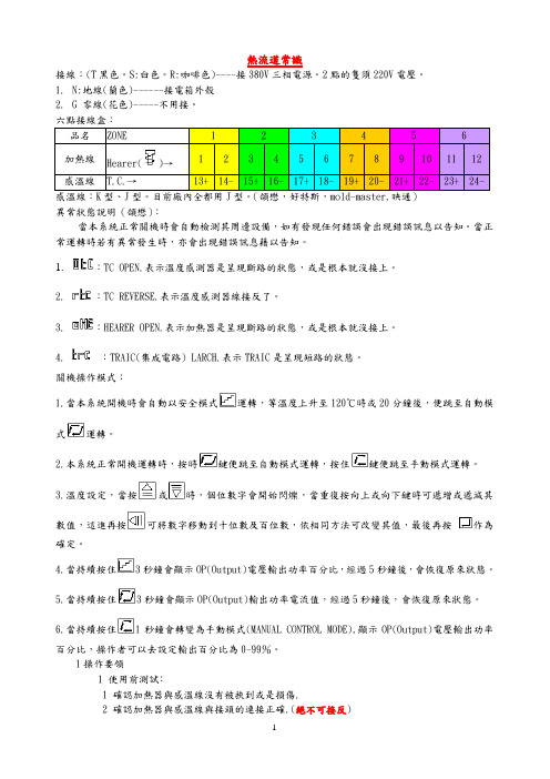
熱流道常識接線:(T黑色。
S:白色。
R:咖啡色)----接380V三相電源。
2點的隻須220V電壓。
1.N:地線(蘭色)------接電箱外殼2.G 零線(花色)-----不用接。
六點接線盒:Hearer(感溫線:K型、J型。
目前廠內全都用J型。
(頜懋,好特斯,mold-master,映通)異常狀態說明(頜懋):當本系統正常關機時會自動檢測其周邊設備,如有發現任何錯誤會出現錯誤訊息以告知。
當正常運轉時若有異常發生時,亦會出現錯誤訊息藉以告知。
1.:TC OPEN.表示溫度感測器是呈現斷路的狀態,或是根本就沒接上。
2. :TC REVERSE.表示溫度感測器線接反了。
3. :HEARER OPEN.表示加熱器是呈現斷路的狀態,或是根本就沒接上。
4. :TRAIC(集成電路) LARCH.表示TRAIC是呈現短路的狀態。
關機操作模式:1.當本系統開機時會自動以安全模式運轉,等溫度上升至120℃時或20分鐘後,便跳至自動模式運轉。
2.本系統正常開機運轉時,按時鍵便跳至自動模式運轉,按住鍵便跳至手動模式運轉。
3.溫度設定,當按或時,個位數字會開始閃爍,當重復按向上或向下鍵時可遞增或遞減其數值,這進再按可將數字移動到十位數及百位數,依相同方法可改變其值,最後再按作為確定。
4.當持續按住3秒鐘會顯示OP(Output)電壓輸出功率百分比,經過5秒鐘後,會恢復原來狀態。
5.當持續按住3秒鐘會顯示OP(Output)輸出功率電流值,經過5秒鐘後,會恢復原來狀態。
6.當持續按住1秒鐘會轉變為手動模式(MANUAL CONTROL MODE),顯示OP(Output)電壓輸出功率百分比,操作者可以去設定輸出百分比為0-99%。
1操作要領1 使用前測試﹕1 確認加熱器與感溫線沒有被挾到或是損傷.2 確認加熱器與感溫線與接頭的連接正確.(絕不可接反)3 確認溫度控制器的配線方式與模具的配線方式是否相同.4 確認射出機的噴嘴與流道板或是熱嘴之進澆處之接觸弧度是否相配.2 使用時注意事項﹕1 將溫度控制器上的溫度設定略高于射出機料管溫度.2 隨著操作情況的變化,逐次調整每一點的溫度.3 當緊急狀況發生需停機處理時,請將每區的溫度降低100 ℃﹐避免塑料在流道板或是熱嘴內熱裂解4由于澆口處極為狹窄,尚有雜質將造成塞頭的現象.5建議在射出機的噴頭使用過濾雜質的濾嘴﹐可避免塞頭清理的危機2 故障排除2 當無無法加溫時﹕1 確認模具上接頭的配線與溫控器是否吻合.2 檢查溫控器的電壓是否正確.3 檢查保險絲是否損壞.4 檢查模具上接頭的接線是否脫落.5 確認感溫線是否短路或損壞.以歐姆表量測加熱器的接線,檢查加熱器是否損壞.3 當無法射出時﹕1確認溫度控制器上的升溫是否足夠塑料的流動.2確認澆口處是否有雜質卡住.3對于某些高溫塑料使用于單穴熱嘴時需要加上后加熱器.4確認熱嘴器尖端處是否塞住澆口.5確認熱嘴與模板間之接觸面是否太大.6確認流道板的部份是否做到溫度平衡及壓力的平衡.4 塑料成型條件參考表面板說明:。
博客热流道:总结十一个热流道的处理工艺

热流道处理工艺大致分为:正火、退火、固溶热处理、固溶处理、时效、处理、淬火、回火、钢的碳氮共渗、调质处理以及钎焊这十一个方面。
一、正火:将钢材或钢件加热到临界点AC3或ACM以上的适当温度保持一定时间后在空气中冷却,得到珠光体类组织的热处理工艺。
二、退火:将亚共析钢工件加热至AC3以上20—40度,保温一段时间后,随炉缓慢冷却(或埋在砂中或石灰中冷却)至500度以下在空气中冷却的热处理工艺三、固溶热处理:将合金加热至高温单相区恒温保持,使过剩相充分溶解到固溶体中,然后快速冷却,以得到过饱和固溶体的热处理工艺四、时效:合金经固溶热处理或冷塑性形变后,在室温放置或稍高于室温保持时,其性能随时间而变化的现象。
五、固溶处理:使合金中各种相充分溶解,强化固溶体并提高韧性及抗蚀性能,消除应力与软化,以便继续加工成型六、时效处理:在强化相析出的温度加热并保温,使强化相沉淀析出,得以硬化,提高强度七、淬火:将钢奥氏体化后以适当的冷却速度冷却,使工件在横截面内全部或一定的范围内发生马氏体等不稳定组织结构转变的热处理工艺八、回火:将经过淬火的工件加热到临界点AC1以下的适当温度保持一定时间,随后用符合要求的方法冷却,以获得所需要的组织和性能的热处理工艺九、钢的碳氮共渗:碳氮共渗是向钢的表层同时渗入碳和氮的过程。
习惯上碳氮共渗又称为氰化,目前以中温气体碳氮共渗和低温气体碳氮共渗(即气体软氮化)应用较为广泛。
中温气体碳氮共渗的主要目的是提高钢的硬度,耐磨性和疲劳强度。
低温气体碳氮共渗以渗氮为主,其主要目的是提高钢的耐磨性和抗咬合性。
十、调质处理:一般习惯将淬火加高温回火相结合的热处理称为调质处理。
调质处理广泛应用于各种重要的结构零件,特别是那些在交变负荷下工作的连杆、螺栓、齿轮及轴类等。
调质处理后得到回火索氏体组织,它的机械性能均比相同硬度的正火索氏体组织为优。
它的硬度取决于高温回火温度并与钢的回火稳定性和工件截面尺寸有关,一般在HB200—350之间。
格润泰热流道简述热流道前因后果,和使用规范
一、前言热流道(Hot Runner)又称无流道(Runnerless mold),是指在每次注射完毕后流道中的塑料不凝固,塑料产品脱模时就不必将流道中的冷却废料脱出。
由于流道中的塑料没有凝固,所以在下一次注射的时候流道仍然畅通。
一般模具使用冷浇道系统时,因热的塑料碰到较冷之模具时使塑料温度降低与摩擦之损耗造成压力下降,以致进到模穴时塑料流动性已经变差造成充填及保压效果变差,而影响成品之形状、外观、尺寸精度及物理性。
若在模具采用热浇道技术,因热浇道温度与射出机射嘴温度相等,可避免了塑料在浇道内的表面冷凝现象,使注射压力损耗小。
而流道废料重复使用会使塑料性能降解,使用热流道系统时没有流道废料,可减少原材料的损耗,从而降低产品成本。
在型腔中温度及压力均匀,塑件应力小,密度均匀,在较小的注射压力下,较短的成型时间内,注塑出比一般的注塑系统更好的产品。
对于透明件、薄件、大型塑件或高要求塑件更能显示其优势,而且能用较小机型生产出较大产品。
二、热流道模具技术之使用近况热流道的技术在1940年在美国被申请了专利,但在起始阶段人们对它的使用不熟悉使发展缓慢,直到1973年爆发了石油危机,原材料价格不断上涨,在各种经济因素促使了热流道迅速发展。
当时热流道系统需求的上升,却也带来了负面影响。
因那时热流道技术还不完美,温度控制的灵敏性差,加热时没有自动的调节控制,使热流道喷嘴很容易被堵塞,不适应塑料的流动性能。
这些原因导致使用需求下降‧而出现了热流道的技术发展停滞阶段,近20年来因有热流道的开发资金增加使技术越趋纯熟,使热流道市场的规模加大。
从总体上讲欧洲与美国使用热流道技术时间较久使用量最多,但在亚洲近年使用之幅度有快速增加趋势。
欧洲、美国虽然模具制造水平较高,但价格较高交货期较长。
相比之下,亚洲的热流道模具制造商在价格与交货期上更具竞争性高。
以TV模具多数使用三板模为例,在2005年时热流道使用数量还少于冷流道,但在2006年时热流道使用数量却多于冷流道40%左右。
恬讯科技教您启动热流道系统
启动热流道系统启动或重新启动分流板系统中的喷嘴按以下步骤来启动或重新启动分流板系统中的喷嘴:1.按照系统的布线图,检查是否所有的连接线(电源和热电偶)都连接到正确的点上了。
2.仅打开分流板上的控制点,将温度设在100℃。
此时温控器的启动模式必须是缓启动,以去除所有部件在运输过程中吸入的潮气。
3.观察打开的控温点是否升温平稳、一致。
4.当所有的点达到100℃后,再等5分钟,然后将温度设为要求的熔料温度+10℃(注射机炮筒的温度应设在熔料温度±5℃)。
5.在等待分流板升温至设定点的同时,用适当的塑料原料在自然的状态下净化注塑机(熔点比正式打件用塑料低一些的塑料比较好)。
粘度较大的原料用于填充绝缘间隙比较好,而且有助于快速换色。
持续的温度会使塑料原料的作用减小,因此要减少色素的堆积和/或驻留的熔料降解。
6.查看注塑机设置。
(第一次启动,注塑机所有的速度和压力参数都应设在低档,以降低任何不可预见的损害。
)●最大注塑压力设在70Mpa(避免第一次注塑因压力过高而使模具爆开)●注塑速度设在30%●注塑量设为正常射胶量的70%(如果制件情况允许)●注塑背压设为30Mpa●为模具设置的最大行程正确●模具合模压力设置在安全数值上●设置的模具合模速度要慢7.分流板的温度大约为设定温度的90%时,也就是加温20分钟后,打开喷嘴的控温点。
●可以一排一排地打开喷嘴,这样便于观察升温。
●第一次给喷嘴加热的方法和第一次加热分流板是相似的。
●将温度设计为100℃,温控器的温控模式应为缓启动。
(以去除所有部件在运输过程中吸入的潮气。
)●观察打开的控温点是否升温一致、平稳。
●当所有的喷嘴温度都达到100℃后,再等5分钟,然后将温度设为要求的熔料温度+10摄氏度,或+35℃。
●一般喷嘴需要5分钟时间来达到设定温度。
8.查看是否所有点的温度都在设定温度,并且稳定。
9.清洗注塑机炮筒。
10.将注塑机料筒缓慢驱动至热流道主料口。
热流道系统的开关机操作

热流道系统的开关机操作文/热恒热流道热流道系统启动之前需要做哪些准备你知道吗?启动之后该如何操作?更换原料怎么做?热恒热流道工程师为您一一讲解:1)准备模具工连接模具的动模、定模和热半模冷却水路,如对动模、定模两侧模温要求不同,则必须连接单独的回圈水路;如对产品外观品质要求高的,建议最好将动、定模两侧的模温单独连接:如热半模侧热流道加热产生的热量较多时,可把其冷却水路单独连接;如热半模侧热流道加热产生的热量被范本吸收或传递散失较多,可接合适温度的模温水以补偿热量损失。
热流道与温控器之间的加热电缆线连接,应按照插头的标志正确连接,并把插头锁扣扣好以防松动。
比如把加热输出电缆线与感温电缆线反接会导致全部热电偶烧毁即开路。
装好模具后先把注塑机螺杆温度升到所需的设定温度,同时也把模温机打开加热,使模具温度升高到生产时所需的设定温度,之后再加热热流道系统至塑胶的工作温度。
需要注意的是,新模的热流道升到设定温度后,需等约5至10分钟(确保加热均匀),如原料中含有玻纤,需更长时间(约10至15分钟),这是因为钨钢嘴尖的传热较差。
(2)开机先查清上次试模时所使用的是何种原料,把注塑机螺杆及射嘴温度调整至该原料在熔融状态时的温度,针对该料选用一种合适的塑胶原料清洗螺杆。
如生产的塑胶中含有LCP + 30%玻纤时,可用纯的LCP料(不含玻纤的)来清洗热流道;开模之后空射,此时应看到各个出胶口的出胶都很顺畅;当发现某支或某几支热嘴不出料时,分以下两种情况:浇口有冷料,可用热风枪烘烤使冷料熔融,然后关上安全门重新射胶;如仍有某支热嘴不出料,根据热嘴位置示意图找出该嘴编号,对应把该支嘴的温度在原值基础上再升高10~20℃之后立即空射(不要超过3次),待出胶通畅之后立刻降温到生产温度,可合模试打产品即可解决问题;此时如仍有浇口被堵,则需立即停止生产,下模拆下堵胶的热嘴清胶或通知供应商处理。
(3)停机等候立刻用纯的LCP 料清洗热流道内的胶料,这样可以保持热流道里面和热嘴头部残留料,在整个生产过程中都是流动性相对较好的LCP料,同时确保下次试模或生产的顺利。
- 1、下载文档前请自行甄别文档内容的完整性,平台不提供额外的编辑、内容补充、找答案等附加服务。
- 2、"仅部分预览"的文档,不可在线预览部分如存在完整性等问题,可反馈申请退款(可完整预览的文档不适用该条件!)。
- 3、如文档侵犯您的权益,请联系客服反馈,我们会尽快为您处理(人工客服工作时间:9:00-18:30)。
5有需要去清洗模具热流道,以便清除被降解了的树脂时。最好
是用背压或最低注射压力(低压手动射胶),切勿使用正常的注射
压力(手动射胶)以免损坏模具热流道。
6使用加玻纤材料停机时,需立即用熔融温度相近的材料冲洗
干净料筒及模具热流道,例如pc料。
7当模具热流道系统达到设定温度时,均热时间(按材料特性而
热流道的操作方法
1所有热流道温度都要参照材料供应商或工程部提供的受控的
温度范围调较,正负值不能超出范围。
2所以一定要遵守,这对于防止漏流/或过压损坏都同样重要。
3使用热流道一定要先将模具运水打开,再打开温控器电源。当电
源接通后,勿随意插入/抽出电的插头,除了容易发生危险之
外,还会损坏控制器。
4如果停机修机或修模将注塑机设置成保温状态,保温温度按材料
11热流道的操作方法。
热流道工作原理解析图:
定),以取得妥当的热膨胀。
8模具热流道系统达到设定温度和均热时间后,需开机生产,不
要仃着机器而长时间开着模具热流道电热,避免材料过热分
解。
9如果热流道内有异物堵塞必需找模房师付进行清理干净后再生 产,不能加高热流道温度来进行运作。
10当热流道设定温度偏差值超出控制范围时,要仃机并通知直属
上司并开单通知相关人员进行检修。
