美国博雷(BRAY)S67(定位器)用于双作用&单作用气动执行器
Bray92-93气动执行器
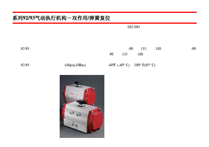
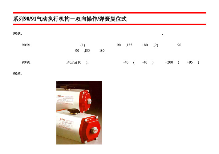
结合了独特的风格,简洁的设计和实用性,美国博雷控制公司提供新的 S92/S93 系列的高性能,优质的气动执行机 构来适应当今市场的需求。 先进的技术,精密的加工制造,经济实用,节省空间。而且,模块设计,可直接安装其他博雷配件,增加其效率和 经济性。 系列 92/93 气动执行机构是齿条齿轮,双活塞设计。分两种型号:双作用-90 度、135 度和 180 旋转度;弹簧复位-90 度旋转。两者能理想的驱动球阀、蝶阀或旋塞阀,并应用于 90 度,135 度和 180 度旋转。手轮和输出轴产生的偏 心负荷正好由低摩擦系数醇缩醛轴承来承受。 系列 92/93 的最高工作压力可达 140psi(10Bar);温度范围从-40ºF (-40º C)至 200º F(95º C)。如需更高或更低的工作 温度,请问博雷厂家或经销商咨询。
数量
说 明
1
外壳
2
活塞
1
齿轮
2
端盖
最大 12 弹簧组合
1
上轴承
1
下轴承
1
保持环
1
尼龙垫圈
2 醇缩醛轴承垫片
2
醇缩醛导环
2
行程限制螺母
2 可调行程限制螺丝
2 行程限制 O形环
1
醇缩醛衬套
1
行程限位
8
六角螺丝
8
垫圈
2
活塞 O形环
2
端盖 O形环
1
上轴 O形环
1
下轴 O形环
1
开度指示
1
开度指示器
标准材料 外壳:挤压铝,经氧化处理
注:不可超过以上最大调节范围
上图所示为系列 93 弹簧复位的组件 *系列 92 双作用不包 含弹簧组件
S70 操作和维修手册-PDF
安装 和阀门的安装.................................................................................................................................................. 3 接线.................................................................................................................................................................. 3 执行器电源输入原则...................................................................................................................................... 4 行程限位开关(凸轮开关)和机械限位螺钉调节 ...................................................................................... 4 关闭过程调节.................................................................................................................................................. 4 开启过程调节.................................................................................................................................................. 4
H66产品说明书201200523
第一章
H66 型 GPS 测量系统简介
1.1 系统的特色、组成 、性能指标及配置 1.1.1 H66 型 GPS 新特色
H66 智能一体化 GPS 接收机现已问世。轻巧的一体化设计能让您充分感受到休闲测量 的快乐,没有外接电缆,没有外接电池,没有外接天线,任何东西都已内置在一个小小的 主机壳里,宽大的液晶显示屏还可让您在采集数据时查看星历情况、卫星分布。该机适合 于不同层次用户,既可当傻瓜机使用,也可使用内置采集器来进行 GPS 数据采集工作。另 外,采用双电源系统,可以自动切换到另一块电池中供电,从而保证不间断测量工作。H66 高达 4G 的内存,能连续长时间采集数据。
H66 型 GPS 测量系统操作手册 6.2.1 导入采集文件 6.2.2 仪器设置 6.2.3 主机注册 6.2.4 升级主机固件 第七章 事后动态差分软件 7.1 软件主要特点 7.2 软件初步使用 7.3 软件功能和菜单介绍 7.4 软件使用典型算例 附录 A 有关专业术语注释 ....................................................................... 错误!未定义书签。 附录 B 年积日计算表 ............................................................................... 错误!未定义书签。 附录 C 联系方式 ..................................................................................... 错误!未定义书签。 附录 D 全国销售及服务网络列表 ............................................................. 错误!未定义书签。
三丰千分表

543-691 543-695 543-692 543-696 543-693 543-682 543-683
543-691B 543-695B 543-692B 543-696B 543-693B 543-682B 543-683B
.5" .5" .5" .5" .5" .5" .5"
.00012" .00012" .00012" .00012" .00012" .0008" .0008"
• 电源开关 • 数据输出 • 数据保持
三大按钮
F
(当连接外部设备时) (当没有连接外部设 备时)
11mm
• 参数设置方式
测量方向转换,公差调整设置,分辨 率转换,刻度因子设置和函数锁设置
• ABS (预置) 和 INC
(调零) 测量方式 之间的转换
实际尺寸
• 公制 / 英制转换功能
F-4
显示表盘可以旋转 330°,可以从所需角度轻松读取测量 结果。
和电池耗尽后,都无需重新设置。
• 采用小型化,以及耐用型电池设计是一
种理想的测量装置。
技术参数
精度 : 参见性能参数 (不包括量化偏差) 分辨率 : 0.01mm 或 .0005"/0.01mm, 显示 : 液晶显示字符高度 8mm 长度基准 : ABSOLUTE 静电线性编码器 最大反应速度 : 无限制 参见性能参数 测力 : 轴套直径 : 8mm (ISO/JIS 型) 或 3/8"(ANSI/AGD型) 测针 : 带有 M2.5x0.45 螺纹的硬质合金球 (ISO/JIS型) 或带有 #4-48UNF 螺纹的硬质合金球 (ANSI/AGD型) 电池 : SR44 (一个), 938882 电池寿命 : 正常使用情况下约为 20,000 小时 尘/水防护等级 : 达到 IP42 防护标准
api610离心泵振动位移监测标准
标题:深度探讨API610离心泵振动位移监测标准在工业生产中,离心泵是一种常见且重要的设备,而振动位移监测标准对于离心泵的运行安全和稳定起着至关重要的作用。
本文将从深度和广度两方面探讨API610离心泵振动位移监测标准,旨在帮助读者全面理解该标准的重要性、实施方法和意义。
1. API610离心泵振动位移监测标准的背景和意义API610是美国石油协会(API)颁布的适用于石油、石化和天然气工业的标准之一,其中包括了离心泵的监测要求和标准。
振动位移是离心泵运行过程中的重要参数,对于监测离心泵运行状态、预防事故和提高生产效率至关重要。
API610规定了离心泵振动位移的监测标准,旨在保障设备运行的安全可靠性。
2. API610离心泵振动位移监测标准的实施方法API610规定了离心泵振动位移的监测方法和要求,主要包括安装振动传感器、采集振动数据、分析振动谱图等步骤。
在实际应用中,可以通过安装振动传感器在泵体、轴承等部位进行振动监测,同时利用振动分析仪器对采集的数据进行分析和诊断,从而判断离心泵的运行状态是否正常,是否存在异常振动位移,及时采取措施进行修理和维护。
3. API610离心泵振动位移监测标准的个人观点和理解从个人观点来看,API610离心泵振动位移监测标准的制定和实施对于保障离心泵设备的安全稳定运行具有重要意义。
振动位移作为离心泵运行状态的重要指标,其准确监测和及时分析能够有效地帮助企业预防事故、延长设备的使用寿命,提高生产效率和安全性。
我认为在实际应用中,企业应该严格遵守API610标准,加强离心泵振动位移的监测和分析,从而最大程度地提升设备的可靠性和安全性。
4. 总结和回顾本文对API610离心泵振动位移监测标准进行了深度和广度兼具的探讨,从背景意义、实施方法到个人观点和理解进行了详细阐述。
通过本文的阅读,读者能够全面了解API610标准的重要性、实施方法和意义,进而加强对离心泵振动位移监测的认识和理解。
美国博雷(BRAY)蝶阀 执行机构 博雷阀门产品系列及配件
70系列电动执行机构亦可提供应 用于流量控制阀门的精确定位。这 一系列阀门的配置为可接收模拟输 入信号的电路板或串行通讯总线, 如DeviceNet。
手动执行器
S1手柄及齿盘
博雷提供两种手柄用于 开关和调节,一种用于1"12"(25mm-300mm)弹性阀 座阀门,另一种用于2-1/2" -8"(65mm-200mm)高压阀 门的大扭拒手柄。90°回转 手柄具有弹簧锁定功能和 指示阀板位置的方向指示 针。同时提供带螺栓的阀 板。对于弹性阀座齿盘有 10个位置是标准的。对于 高压阀齿盘有八个位置是 标准的。两种阀门都配有 限位开关以防阀门旋转过度。另外 提供非限位位置板,180°槽板,一 个记忆限位及一个2"方形螺帽。
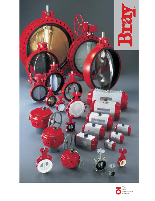
博雷忠实服务于客户。我们的 员工训练有素,对博雷各类产品了 如指掌,给予客户一对一的服务。 此外,博雷还有经验丰富的经销商, 在世界范围内为我们的客户提供优 质服务。
根据博雷标准设计的产品系列 具有极高的兼容性、经济性,性能 优异,为现代工业的应用提供了优 质的选择。
弹性衬胶阀门 博雷提供的全系列弹性 衬胶蝶阀应用广泛,性能 可靠,经久耐用。 其 独 特 性 在 于 , 我 们 的 阀门能够与绝大多数法兰 标准兼容。因此,同一种阀门可 适应不同市场的需求。另一个特 性是我们的舌槽式阀座设计可以 完全阻隔流体渗入阀体和阀杆。 大多数标准阀体使用聚酯涂层确 保了良好的防腐性能并且阀门表 面不易受到磨损。博雷阀门在颈 部均有加长设计,与管线至少有 50mm的距离。阀门顶盘连接法兰 符合ISO5211标准,可直接连接手 柄或执行机构。阀门有对夹式、 支耳式和双法兰式,连接方式符 合ANSI125/150法兰标准。
BPS(条码定位)

16 (8) ms ±1 (2) mm 500 value/s 0.01 mm 起 0 °C ~ 40 °C -30 °C ~ 40 °C 0 °C ~ 50 °C IP 65 PROFIBUS DP/SSI 90 –170 mm 10 m/s 10 – 30 V DC 2 级,符合EN 60825-1
劳易测电子贸易(深圳)有限公司 规格如有更改,恕不另行通知
版权所有
处理几乎任何事情,长度可达 10,000米
劳易测电子条码定位系统的第二个重要部件就是条码带。使用照相排字技术,按一 定的间隔,在非常坚固和高弹性的自粘胶带上打印出独特的防紫外线条码。位置值 还为“纯文本”形式打印,以方便辨认。条码带长度可达 10,000 米,可以非常简 单地粘贴在传输路径上,并且水平曲线和垂直曲线很好地保持一致。如果条码带受 损,可从因特网上下载适当的临时条码打印替换,将特殊标签集成到条码带,条码 阅读器还可以控制具体的功能,比如速度变化或传输带变轨应用等。
劳易测电子贸易(深圳)有限公司上海分公司 Leuze electronic Trading (Shenzhen) Co., Ltd. Shanghai Branch 上海市虹口区大连路 1619 号骏丰国际财富广场 805 室 Rm. 805, Junfeng International Fortune Plaza No. 1619, Dalian Rd., Hongkou District, Shanghai 200086 P. R. China Tel : +86 (0) 21 5508 5630 Fax: +86 (0) 21 5508 5631 E-mail: info_sh@
劳易测电子条码定位系统独特产品系列,具有许多优点是其它解决方案无法匹敌的。
美国博雷(BRAY)蝶阀 执行机构 博雷阀门产品系列及配件

S32/33 24"-36"(600mm-900mm)
S32/33为大口径经济型对夹式 阀门。32系列的额定压力为75psi (5bar),33系列额定压力为150psi (10bar)。(图中无显示) S35/36 24"-72"(600mm-1800mm)
S35/36为大口径双法兰阀门。 特点为阀杆一体式设计,可调整 填料和良好的气密性。35系列阀 门额定压力为75psi(5bar),36系 列阀门额定压力为150psi(10bar)。
控制蝶阀
博雷控制阀门集控制精确和气密 性良好的特性于一身。先进的数字 控制执行机构加上蝶阀本身固有的 特性使得该系列阀门能够迅速对控 制信号作出反应。其它特点包括: 大流量,维修便捷,独特的能与 PLCs和计算机指令信号兼容的界面。
博雷的弹性阀座控制蝶阀规格为 1"-24"(25mm-600mm),阀体可提 供各种材料,有对夹式、支耳式和 法兰式。阀板材料有镀尼龙11涂层 的球墨铸铁、铝、铜、不锈钢或 PTFE, UHMWPE包覆不锈钢等。压 力等级从真空175psi(12bar), ASME/ANSI等级150,300和600。 非防火型阀门和防火型阀门符合 API607第四版标准的阀门也有提供。
S30/31 2"-20"(50mm-500mm) S30/31为博雷通用阀门系列。 具有高强度整体式设计特点。通 过精确的双"D"阀板与阀杆的连接 驱动阀板而无需螺丝和钉梢。这 种设计使得流量系数较高,拆卸 便捷,减少了阀板对阀杆的错误 率。阀杆用不锈钢保持环固定在 阀体内。30系列对夹式和31系列 的支耳式2"-12"阀体的额定压力为 175psi(12bar),14"-20"阀体压力为 150psi(10bar)。2"-12"阀体管线 末端的额定压力为75psi(5bar), 14"-20"阀体管线末端的额定压力 为50psi(3.5bar)。
Si操作手册

输入通道.........................................................................................3 ‐ 1
输入面板概述.................................................................................................. 3 ‐ 1 INPUT FADER SELECT输入推子选择按键(推子层选择).................. 3 ‐ 2 输入通道推子.................................................................................................. 3 ‐ 3 ON按键............................................................................................................ 3 ‐ 3 SOLO按键....................................................................................................... 3 ‐ 3 SELect按键...................................................................................................... 3 ‐ 4 输入通道状态窗口.......................................................................................... 3 ‐ 4 旋钮.................................................................................................................. 3 ‐ 4
罗克韦尔 ControlLogix 系统 说明书

准备事宜 . . . . . . . . . . . . . . . . . . . . . . . . . . . . . . . . . . . . . . . . . . . . . . . . . . 19 1756-L7x 控制器部件. . . . . . . . . . . . . . . . . . . . . . . . . . . . . . . . . . . . . . 19
未随 1756-L6x 控制器提供的部件. . . . . . . . . . . . . . . . . . . . . . 33 1756-L6x 控制器安装. . . . . . . . . . . . . . . . . . . . . . . . . . . . . . . . . . . . . . 34 CF 卡的安装和取出 . . . . . . . . . . . . . . . . . . . . . . . . . . . . . . . . . . . . . . . 34 电池的连接与更换 . . . . . . . . . . . . . . . . . . . . . . . . . . . . . . . . . . . . . . . . 38 将控制器插入机架 . . . . . . . . . . . . . . . . . . . . . . . . . . . . . . . . . . . . . . . . 40 将控制器从机架拆下 . . . . . . . . . . . . . . . . . . . . . . . . . . . . . . . . . . . . . . 42
安装 1756-L7x 控制器 安装 1756-L6x 控制器
控制器使用入门
Micropilot FMR67 HART 雷达物位仪 简明操作指南说明书
Products Solutions Services简明操作指南Micropilot FMR67HART雷达物位仪本文档为《简明操作指南》;不得替代设备随箱包装中的《操作手册》。
设备的详细信息请参考《操作手册》和其他文档资料:所有设备型号均可通过下列方式查询:–网址:/deviceviewer–智能手机/平板电脑:Endress+Hauser Operations AppKA01253F/00/ZH/02.1771355420Micropilot FMR67 HART2Endress+HauserMicropilot FMR67 HART 目录Endress+Hauser 3目录1重要文档信息 (4)1.1图标................................................................................41.2术语和缩写..........................................................................61.3注册商标 (7)2基本安全指南 (8)2.1人员要求............................................................................82.2指定用途............................................................................82.3工作场所安全.........................................................................82.4操作安全............................................................................82.5产品安全............................................................................93产品描述 (10)3.1产品设计 (10)4到货验收和产品标识 (11)4.1到货验收...........................................................................114.2产品检验 (11)5储存和运输 (13)5.1储存条件...........................................................................135.2将产品运输至测量点 (13)6安装 (14)6.1安装条件...........................................................................146.2安装:水滴天线,PTFE 材质,口径50 mm / 2"..............................................196.3安装:天线,齐平安装.................................................................206.4FMR67的空气吹扫接口................................................................226.5带保温层的罐体......................................................................256.6旋转变送器外壳......................................................................256.7旋转显示模块........................................................................266.8安装后检查.........................................................................267电气连接 (27)7.1连接条件 (27)8调试(通过操作菜单) (43)8.1显示与操作单元......................................................................438.2操作菜单...........................................................................468.3解锁仪表...........................................................................478.4设置操作语言........................................................................478.5物位测量设置........................................................................488.6用户自定义应用......................................................................49重要文档信息Micropilot FMR67 HART 1 重要文档信息1.1 图标1.1.1 安全图标1.1.2 电气图标1.1.3 工具图标4Endress+HauserMicropilot FMR67 HART重要文档信息1.1.4 特定信息图标1.1.5 图中的图标1.1.6 设备上的图标Endress+Hauser5重要文档信息Micropilot FMR67 HART 1.2 术语和缩写6Endress+HauserMicropilot FMR67 HART 重要文档信息Endress+Hauser 71.3 注册商标HART®HART 通信组织(Austin,美国)的注册商标KALREZ®, VITON®杜邦高性能弹性体公司(Wilmington,美国)的注册商标TEFLON®杜邦公司(Wilmington,美国)的注册商标基本安全指南Micropilot FMR67 HART8Endress+Hauser2基本安全指南2.1人员要求操作人员必须符合下列要求:‣经培训的合格专业人员必须具有执行特定功能和任务的资质。
美国博雷(BRAY)TRIAD(3片式球阀)

真空:29英寸汞柱
部件及材料
阀门尺寸: 3” 和 4” 阀门型号: • FP - 全径
压力/温 度
2400 2200 2000 1800 1600 1400 1200 1000
800 600 400 200
-50 0 100 200 300 400 500 600 700
7 6A 6B 9
2
序号 名称
•焊接口用 CF3M.
不锈钢 ASTM A351 Gr CF8M ASTM A351 Gr CF8M • ASTM A351 Gr CF8M TFM ASTM A479 Type316 石墨 TFM ASTM A193 B8 SS316 PEEK PEEK 50% SS316 + 50% PTFE 石墨 SS304 SS301 SS300 SS304 SS300 SS304 SS304 乙烯树脂 SS304
外部泄漏,现场装载石墨阀杆填料防
止阀杆泄漏。
阀体
阀体
阀盖
阀座
球体
阀座与球体 的接触
燃烧前
阀盖
球体
阀盖和球体 金属与金属 的接触
燃烧后
此 外 , 安 装 板 可 以 实 现 简 便 的 F l o w -Te k 介 质 储 存 单 位 的 现 场 安 装。该部件与双重阀体密封一起可应用于无排放繁重作业、起 重和半地温或高循环作业。
止推轴承
• 聚醚醚酮
石墨 阀体密封 TFM 阀体密封
防火安全:API 607-4 验证
F l o w -Te k 的 双 阀 体 密 封 , 阀 杆 及
石墨阀杆填料,金属球体和阀体构成
了具有在极端情况下极高的防火安全
性。在火灾情况下,过高的热量破坏
西门子定位器官方版说明书
2
定位器的供货范围
2 定位器的供货范围
• 订购的定位器
型号
不带 HART
塑料壳 塑料壳 金属壳 塑料壳 塑料壳 金属壳
带 HART 带 HART
塑料壳 塑料壳 金属壳
塑料壳 塑料壳 金属壳
单作用 双作用 单作用 单作用 双作用 单作用
单作用 双作用 单作用
单作用 双作用 单作用
Not Ex Not Ex Not Ex CENELEC/FM CENELEC/FM CENELEC/FM
7.1.1 直行程执行机构的初始化................................................................................................ 16 7.1.2 直行程执行器手动初始化................................................................................................ 17 7.2 角行程执行器调试准备 .............................................................................................................18 7.2.1 角行程执行机构的自动初始化 ......................................................................................... 19 7.2.2 角行程执行机构手动初始化.............................................................................................20 7.3 复制初始化数据 定位器置换 ................................................................................................21 7.4 故障校正 .................................................................................................................................21 7.5 阀门定位器简明操作指南..........................................................................................................24 SIPART PS2 6DR5xxx-xx 散页 操作 简要说明 .................................................................................27 附录 ...................................................................................................................................................... 29
BAR比例定位器
-posi turn2Sicher und fl exibel –die neue Antriebsgeneration actubar2Operating Instructionsbar-positurn2In this documentation we use different ty-pes of instructions for safety and warning signs:Indicates a real and near dan-ger.To ignore this sign means pos-sible death or serious injury as consequence.Indicates a threat of danger. To ignore this sign means pos-sible serious injury or material damage as consequence.Indicates a possible danger. To ignore this sign means pos-sible material damage as con-sequence.Stands for advice and tips for a better understanding of in-structions or a better handling of the unit.tions are valid for positurn2, a module of the new valve control system bar-vacotrol. They are intended for the operator that me-ans the person that works with the unit. This is not a technical handbook. For que-stions, arising from the contents of this do-cumentation, please contact our customer service department.The unit and this documentation are pro-tected by copyright. Their reproduction wi-thout written permission will be contested in court. We reserve all rights to these operating instructions and their contents thereof, also for their reproduction and/or duplication in whatever imaginable form, e.g. through photocopies, print, on whate-ver data carriers or in whatever translated form. The reprinting of this documentation is only possible via the express written per-mission of bar GmbH. The technical state at the time of delivery of the unit and in-structions is a deciding factor, in case no other information is provided. We reserve the right to technical changes without spe-cial notice in advance. Earlier instructions lose their validity. The General Terms and Conditions for Sales and Delivery as pre-scribed by bar GmbH are to be adhered to.Copyright:DANGER!WARNING!ATTENTION!Operating Instructions bar-positurn2product according to our advertising, the product information and this documentati-on issued by us. Further product features are not promised. We undertake no liability for economy and fault-free function, when the product is used for other purposes, as described in the section …Intended Use“. Damages are generally excluded, except in the case of criminal intent or gross negli-gence committed by bar is proved, or in the case of promised product features being absent. If this product is exposed to non-prescribed environments, for which it is not suitable or does not correspond to the technical standard as stipulated therein, we cannot and will not be held responsible for the consequences.We accept no liability for damages to sy-stems and equipment in whatever form in the surrounding environment around the product, which result from a fault of the product or in this documentation. We are not responsible for injuries to patents and/ or other third party rights outside the Fe-deral Republic of Germany.We cannot be held liable for damages, re-sulting from the incorrect operation and non-adherence to the instructions laid down in this documentation. We are not li-able for losses in profi t and resulting dama-ge thereof from the non-adherence to safe-or consumable products, which have been neither delivered nor certifi ed by bar.The products manufactured by bar GmbHare designed to give a long service life. They correspond to the state of the art for science and technology and are individu-ally tested in all functions before dispatch.The electrical and mechanical construction corresponds to valid standards and guide-lines. bar constantly carries out ongoing tests on the products and the marketplace,to ensure the further development and im-provement of their products.In case of faults and/or technical problems, please contact our service department. Wecan assure you, that immediate appropri-ate measures will be initiated. Valid hereare the Terms of Warranty from bar GmbH, which we will send to you upon request.The positurn2 is a positioner for mountingonto pneumatic actuators of the series known as the actubar series or actuators according to VDI/VDE 3845 with a pivoting angle of max. 180°. With the help of ex-ternal solenoid valves and compressed air,the positurn2 converts analog input signalsinto actuator pivoting movements. Usageas a 3-position control unit with freely se-Designated Usage:3Operating Instructionsbar-positurn2 on indicator without any activation.Any other application of this device is to beconsidered to be outside the designateduse. If you have any questions, or wouldlike to use the unit for another purpose,please contact our customer service de-partment. We will be pleased to help withthe necessary confi gurations.For this device, we undertake the warrantyof faultless condition for a duration of sixmonths within the framework of our Con-ditions of Warranty. Parts subject to wear-and-tear are excluded from this warranty.The claim is invalidated, when tampering iscarried out by persons who are hereby notauthorised by bar GmbH.Inside the warranty period of time, we willrepair damage or faults without cost, whichcan be provenly traced back to a factoryerror, insofar as this is registered by usimmediately upon discovery, at the latesthowever inside a time span of six monthsfollowing the date of delivery. The warrantycover will be made according to our estima-tion, through cost-free repair maintenanceof the faulty part(s) or exchange of thoseparts with faultless parts.Send the units, for which the claim againstwarranty is being made, carriage-paid andfore sending the goods.The owner/operator of this device has toensure that only persons who• k now the rules about safety at work andprevention of accidents• h ave been instructed in the operation ofthis device• h ave completely read and understoodthese instructionscan use and operate this device. Persons,who operate this device, are obliged:• t o observe all rules pertaining to safetyat work and the prevention of accidents• to read these instructions thoroughly.Persons to be seen as authorised, are tho-se with a successfully concluded professi-onal training, technical experience, as wellas knowledge of the appropriate standardsand guidelines, and who are in a position,to appreciate the tasks they are delegated,and lastly to recognise and act upon possi-ble dangers arising.Operators of the positurn2Persons to be seen as authorised, are tho-se who have been instructed in the opera-Guarantee:Obligations of the Customer:Authorised Personnel:4Operating Instructions bar-positurn2Personnel for Installation and Care Persons to be seen as authorised, are tho-se who have been instructed in the impor-tance and consequences of a positioner and have read and fully understood these instructions.In its standard form, the positurn2 is desi-gned & manufactured for actuators with a closing direction for valves in a clockwise manner (cw). The actuator undertakes the basic position with a closed valve. In the case of corresponding units, the basic position corresponds to so-called safety ef-fect ”current-free closed“In the initialisation process, the positioner adjusts to the defined actuator pivoting range. The analog activation is triggered from the control point and effects the pro-portional allocation of the defi ned pivoting angle to the set value (input) signal.In a similar manner, the defi ned pivoting angle is allocated an analog positioning signal.Binary signals are formed additionally at the start and end of the pivoting range. Electrical connection is made at terminal blocks inside the unit. Pneumatic connec-tion is made directly at the external sole-noid valves.• or directly onto actuators type actubar. Solenoid valves are fi tted to standard inter-faces with type-related material.Functional Description:5Operating Instructionsbar-positurn2Pivoting angle10° to 190°Protection Type IP 65Mounting position randomAmbient temperature-20°C to +70°CAmbient humidity10-90%, non-condensingWeight Without valve ca. 0,65 kgVa riant D Mini-valves: ca. 1,0 kg Midi-valves: ca. 1,1 kgVariant S Mini-valves: ca. 1,2 kg Midi-valves: ca. 1,4 kgVariant E Mini-valves: ca. 1,2 kg Midi-valves : ca. 1,4 kg Analog c ontrolsignalEffective direc-tionreversible by sliding switchActuating signal Signal type selectable 4-20 mA, 0-10 V, inverse polarity-protection, proportional to pivoting anglePre-resistor > 1 kOhm at 0-10 V; < 500 Ohm at 20mADead-zone± 2% of nominal pivoting angleTravel s peed Adjustable by t hrottles in solenoid valvesPosition s ignal Signal type selectable 4-20 mA, 0-10 V, nominal, active, inversepolarity protection, proportional pivoting angleResolution < 0,5% of nominal pivoting angleLimit feedback Voltage12-28 VDCSystem Opto-coupler, short-circuit-proof; 1 kOhm series &10 kOhm parallel resistance fittedIndication 3% of nominal pivoting angle b efore initiated endpositionSupply24 VDC (21 bto28 VDC), inverse polarity p rotectionPower Variant D Mini-valves: 1,8 W M idi-valves: 4,2 Wconsumption Variant S Mini-valves: 3,6 W M idi-valves: 7,2 WVariant E Mini-valves: 3,6 W M idi-valves: 7,2 W Terminal strip Clamping range up to 0,75 mm²Cable to P CS7 to 13 mm, 0,5 mm2, random cable lengthBinary inputsignalsON/OFF valves < 10 V for …0“;> 18 V for …1“Operating pres-sure2,5 to8 barAir Quality Filtered air acc. to DIN ISO 8573-1/Class 467Operating Instructionsbar-positurn2Delivery and Unpacking:Pneumatic scheme for positurn2 PN2-D PN2-E (single-acting) PN2-S (double-acting)Please note the unit-specifi c safety descriptions on pages 13 and 14.The unit is dispatched from bar and trans-ported by selected transport companies i.e. parcel services. At the point of arrival on your premises you should check the fol-lowing:• A re the number of packages that arrived the same as on the bar delivery note?• I s the packaging free from visible signs of damage?• A re the unit(s) and the accessories free from visible signs of damage?• A re there any signs of careless handling during transport (e.g. burn marks, scrat-ches, paint)?To be able to present all claims against the transport companies, you should do-cument all possible transport damage (e.g.with photographs and a written report), be-fore you unpack the unit. bar is not respon-sible in any way for transport damage and can not accept responsibility or liability in any way whatsoever.Carefully remove the transport packaging. Please observe all laws and regulations for the disposal of packaging materials.The positurn2 comes supplied with the external solenoid valve version D, S or E – depending on the actuator type and safety concept. There is a mounting bracket for mounting onto actuators with protruding shaft.Check the scope of delivery with the de-livery note and the order documentation.Controlling the Delivery:Scope of Delivery:Pneumatic schemes for the safety-orientated positurn2Operating Instructionsbar-positurn2Mounting, Electrical Connection, Initialising and Commissioning:MountingMounting may only be carriedout by suitably trained skilledpersons. Otherwise there is thedanger of an incorrect installa-tion.• O pen the positurn2 and set it onto theactuator.• T ake special care to avoid the entry ofdust, dirt and moisture getting into theopen housing of the positurn2 duringmounting & commissioning• G uide the base of the positioner into thecorresponding groove at the actuator.WARNING!89Operating Instructionsbar-positurn2Electrical Connection:Positionertake care to see that the symbol position coincides with the valve function.lead-throughs of the protective cover.Electrical installation may only be carried out by suitably quali fi ed & skilled persons.Otherwise there is a real dan-ger of electric shocks.WARNING!Operating Instructionsbar-positurn210Do not damage switch!123564Operating direction switch Potentiometer Initialising switchProgram Switch:1 = P ositioner mode ON = 3-Position modeCurrent / Voltage switches123456Set current / voltage switches according to the signal type for the unit.Initialising (learning the end positions and other specifi c data):Note:When initialising, the operating direction switchmust be set in accordance with the operating direction of the valve actuator, in order to ascertain the real func-tion correctly. In real operation, the operating direction switch may be adjusted when the increase in signal for special cases is to be changed.• Check whether the operating direction switch has been set in accordance with the operating direction of the actuator(L/ccw or R/cw).• Make the electrical connections accor-ding to the connection diagram.• Select program: 1:PositionerOn: 3-Positionmode• Set initialisation switch J0 to …Init“. • Establish power supply.fall 4 Status-LEDs illuminateorternating terminals 1 and 2 with terminal 13 (24 VDC).• T he end positions must be fully reached at least 2 times. Take care to see that the compressed air fl ow comes to a standstill.• C onnect digital input terminal 3. If there is no external digital input available for activating the function “Positioner“, layNot valid for 3-Position mode!• Set sliding switch J0 to …Run“. • S et the middle position at the 3-Position control unit via the integrated potentio-meter.f T he green status-LED illuminates and a yellow LED illuminates depending on the particular end position.Description of Safety Functions: Unit type: PN2-D• Digital Input Terminal 3 missing• C urrent supply Terminal 13 + 14 missing • Analog input Terminal 8 missing • Analog input Terminal 8 < 2mA Unit type: PN2-S• D igital Input Terminal 3 missing• C urrent supply Terminal 13 + 14 missing • Analog input Terminal 8 missing • Analog input Terminal 8 < 2mAUnit type: PN2-E• Digital Input Terminal 3 missing• C urrent supply Terminal 13 + 14 missing • Analog input Terminal 8 missing • Analog input Terminal 8 < 2mA f Valve stays in last positionf Valve stays in last positionf Valve stays in last positionf Valve stays in last positionf Valve moves to safety position f Valve moves to safety position f Valve moves to safety position f Valve moves to safety position f Valve moves to safety position f Valve moves to safety position f Valve moves to safety position f Valve moves to safety positionPositioner mode 4-20 mA:f Valve stays in last position f Valve stays in last position f Valve moves to safety position f Valve moves to safety position f Valve moves to safety position f Valve moves to safety position f Valve moves to safety position f Valve moves to safety positionf Valve stays in last positionf Valve stays in last position f Valve moves to safety position f Valve moves to safety position f Valve moves to safety position f Valve moves to safety position f Valve moves to safety position f Valve moves to safety position• C urrent supply Terminal 13 + 14 missing • Analog input Terminal 8 missing Unit type: PN2-S• Digital Input Terminal 3 missing • C urrent supply Terminal 13 + 14 missing • Analog input Terminal 8 missing Unit type: PN2-E• Digital Input Terminal 3 missing • C urrent supply Terminal 13 + 14 missing • Analog input Terminal 8 missingUnit type: PN2-3P-D• Digital Input Terminal 1, 2 + 3 missing • C urrent supply Terminal 13 + 14 missing Unit type: PN2-3P-S• Digital Input Terminal 1, 2 + 3 missing • D igital Input Terminal 1, 2 + 3 missing Longer than 3 seconds• Current supply Terminal 13 + 14 missing Unit type: PN2-3P-E • D igital Input Terminal 1, 2 + 3 missing • D igital Input Terminal 1, 2 + 3 missing Longer than 3 seconds • C urrent supply Terminal 13 + 14 missing3-Position mode:actuator and valve compo-nents! Set and secure the me-chanical end positions of the actuator.E nd positionadjustment screwsThrottlesUse the throttles at the pneumatic valves to set the actuating speed of the actuator. Standard setting: minimum 5 seconds pivoting time for 90° pivoting angle.• I f so required, shorten the cable in the solenoid valve wiring or coil it together in a tidy manner and bind toge-ther with cable-ties.• I f so required, the coils in the solenoid valves can be ex-changed. Take note here to keep the same cabling sys-tem and to initialise anew. • D o not close the throttle com-pletely; the consequence will be that no actuator function will follow.• W hen using manual operation at the pneumatic valves you have to return them to the in-itial position afterwards.• A fter every change in the end position and re-assembling the actuator, do not forget to make a new initialization.12ATTENTION!2Never use aggressive clea-ners or materials to clean the housing of the positurn2. This can lead to damage to the vie-wing glass or paintwork.• C lean the housing of the positurn2 with a clean, slightly moistened cloth.• I n the case of hardened-on dirt, use a normal household cleaner according to the instructions on the packaging on the cleaner.Never open the protective co-ver above the delicate electro-nics. This can lead to damage to the unit and the loss of all warranty claims.• T he positurn2 works maintenance-free. In case of defects, which take place in-side the warranty time, remove the po-siturn2, and after telephoning us, send it to the address as shown on the rear side.electrical connection data in the operating instructions has to be strictly adhered to.Manufacturer: bar GmbH • Auf der Hohl • 53547 Dattenberg Machine Description: bar-positurn2Machine Type:PN2-D, PN2-E, PN2-S, PN2-3P-D, PN2-3P-E, PN2-3P-S Appropriate EC Guidelines:EMV Guidelines 89/336/EWGUsed Standards and TechnicalSpecifi cations: EN61000-4-1:2001EN 61000-4-2:2001EN 61000-4-3:2001 and A11:2004EN 61000-4-4:2001EN 61000-4-5:2001EN 61000-4-6:2001EN 61000-6-3:2001EN 61000-6-4:2001V DI/VDE 3845 (Interfaces Valves, Actuators,Auxiliary Devices)Dattenberg, 01.02.2011 © bar pneumatische Steuerungssysteme GmbHbar pneumatischeSteuerungssysteme GmbHAuf der Hohl 153547 Dattenberg/Germany Tel. +49 (0) 2644 - 96070Fax +49 (0) 2644 - 960735www.bar-gmbh.de sales@T e c h n i c a l d e v e l o p m e n t a n d c h a n g e o f d a t a s i s r e s e r v e d . © b y b a r G m b H – 03/2011www.bar-gmbh.de。
bray气动阀门S90-91中文说明书
D
8
10
13
13
22
22
22
12
16
E
74 110 130 137 176 196 240 296 338
F*
see dwg.
132
177
202
215
290
368
450
665
G
M5 M6
M8
M8
M8
M8 M12 M12 M16
(UNC) ×6
×8
×8
×10 ×10 ×10 ×14 ×14 ×19
H (UNC)
转动及供应的连接支架或套板。
BACK NEXT
系列90/91气动执行机构-双向操作/弹簧复位式
4 通与 3 通电磁阀 系列 63 用于气动执行机构“开关” 的电动操纵。系列 63 电磁阀 采用 NEMUR 标准可直接安 装在执行机构上。防水型为: (NEMA 4,4X)防水防爆型(NEMA 4,4X,7,9)。空气接 管尺寸:1/4”NPT:电线连接;1/2”NPT。 手动现场操纵杆位于电磁阀之上。系列 55 速度控制阀可 以独立地控制执行机构开关的速度。3 通电磁阀,请与博 雷或代理商咨询。 气动定位器 系列 64 在需求调节阀门工况下采用 气动定位器系列 64 可准确地 指示阀门角度介于 0-90 度。 标准控制信号是(0.2)至(1.0) 巴(3-15psi)。它可用于双作用 或单作用弹簧复位气动执行机构上。 亦可用于需要有逆或分区范围。直接安装在执行机构。
—
M8 ×10
M8 ×10
—
M10 M12
×4
×14
—
M16 M16 ×19 ×19
J
—
22
导航一体机用户手册1.4

导航一体机用户手册江苏天泽信息产业股份有限公司2011年5月目录声明事项 (4)注意事项 (5)阅读说明 (5)1概述 (6)1.1技术规格 (6)1.1.1GPS接收性能 (6)1.1.2物理性能 (7)2基本操作 (7)2.1操作方式 (7)2.2系统关机 (7)2.3界面介绍 (8)2.3.1主菜单界面 (8)2.3.2GSM信号和SIM卡检测 (8)2.3.3GPRS连接状态 (9)3具体操作 (9)3.1汽车导航 (9)3.2一键通 (9)3.3扩展应用 (10)3.3.1IC卡登录 (11)3.3.2条形码扫描 (11)3.3.3RFID (12)3.4CAN信息 (13)3.5摄像头 (14)3.6电话短信 (15)3.6.1电话 (16)3.6.2拨号 (17)3.6.3电话簿 (18)3.6.4通话记录 (20)3.6.5短消息 (20)3.6.6写消息 (21)3.6.7收件箱 (23)3.6.8发件箱 (24)3.6.9草稿箱 (25)3.7娱乐 (26)3.7.1视屏播放 (26)3.7.2音乐播放 (28)3.7.3图片浏览 (29)3.7.4电子书阅览 (30)3.8调度信息 (31)3.8.1中心信息 (31)3.8.2救援信息 (32)3.8.3定期定点 (36)3.9收音机 (40)3.10系统设置 (41)3.10.1路径设置 (42)3.10.2背光设置 (43)3.10.3按键声音 (44)3.10.4一键通设置 (44)3.10.5星历信息 (45)3.10.6IP设置 (46)3.10.7系统信息 (46)4软件升级 (48)5附录 (48)5.1运输与存储 (48)5.2保养与维护 (48)声明事项声明1:全球卫星定位系统(GPS)是由美国政府所控制的,也是由美国政府来保证其精确度以及进行维护的。
如果该系统进行改动,将会影响所有GPS设备的精度和性能。
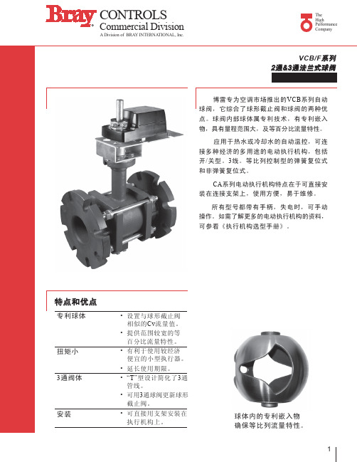
美国博雷(BRAY)VCB F系列 2通3通法兰式球阀
C B
B
D
1/2 A
A
C
2 通尺寸
A
3 通尺寸(侧视图)
A
3 通尺寸(俯视图)
3通带球体嵌入物的阀门
连 in. 4 5 6 接 mm 100 125 150 孔数 8 孔直径 Φ19 A in. 12 14 16 mm 305 356 406 in. 9 10 11 B mm 229 254 279 in. 14 15 16 C mm 356 381 406 D* in. 18-1/2 20 20-1/2 mm 470 508 521 重 lb 75 90 105 量 kg 34 41 48
2
CONTROLS
R
Commercial Division
A Division of BRAY INTERNATIONAL, Inc.
The High Performance Company
2通带球体嵌入物球阀选型表
连 in. 2-1/2 接 mm 63 型号 # 1 VCB2723A_ VCB2724A_ VCB2725A_ VCB2826A_ VCB2827A_ VCB2828A_ VCB4091F2 VCB4152F2 VCB4254F2 VCB5185F2 VCB5240F2 VCB5400F2 VCB6348F2 VCB6441F2 VCB6650F2 流量系数 Cv 55 72 202 82 124 145 91 152 254 185 240 400 348 441 650 Kv 47 62 174 71 107 125 78 131 218 159 206 344 299 379 559 闭合时 P 2 值 PSI kPa
阀体压力 连接端口 温度范围 材 质 阀 体 球 体 阀 杆 球体嵌入物 阀杆密封 (2) 阀 座
- 1、下载文档前请自行甄别文档内容的完整性,平台不提供额外的编辑、内容补充、找答案等附加服务。
- 2、"仅部分预览"的文档,不可在线预览部分如存在完整性等问题,可反馈申请退款(可完整预览的文档不适用该条件!)。
- 3、如文档侵犯您的权益,请联系客服反馈,我们会尽快为您处理(人工客服工作时间:9:00-18:30)。
带防护外壳的智能型 总线连结定位器 (转换开关板已拆)
助找出产生问题的原因。对供气 过程中的气动输出(0-100%) 可直接控制,这样可对定位器的 气动部分做出检测, 对阀门或执 行器中可能发生的堵塞也可进行 检测。在就地控制模式中可手动 设定输入。
自我检测并作防护的性能包括 根据阀门位置对节点进行控制偏 移,其依据是从某节点开始的行 程秒数和百分比,循环次数和所 达到的全冲程范围,通过压力感 应器的输出气流压力,和定位器 温度,监控供气情况。
智能数字定位器
67系列智能数字电、气动定 位器由微处理器控制,在常规的 4-20毫安的摸拟控制信号下,可 将的所有的数字性电子信号传输 到气动执行器上。微处理器不断 地将指令信号和阀门的实际位置 进行比较,并作精确调整直到这 两个测定值在用户可选择范围内 能相互吻合。当按下自动开启按 钮时,校正与配置过程就能自动 运行了。
智能总线连接型定位器和数 字定位器都有带自校准的自动启 动及由按纽、指示器组成的配置。 复杂的分压计和开关组件都被取 消了-只需要按下按纽,即可进行 配置。自动开启能决定机械行程 限位的停止, 记录叁数并通过运用、 分析选点突跳,不断地使控制性 能、双向行程次数最优化。 控制 性能叁数就是定位时间上的增益, 阻尼和滞后。 这些叁数能自动设 置,用于不同的开关应用,用户 也可自行调整。以上设定需储存 在稳定的记忆模块中以避免由于 断电而造成的损失。在进行完自 动开启这一步后,定位器就可以 准备运作了。
控定位器的先进性。
博雷67系列电气动定 位器能使阀门定位在精确 的位置上,具有创新,卓 越的性能及良好的流量控 制特性。该产品有三种类 型-总线智能型,数字智能 型和摸拟型。设计紧凑使 得功能性模块可以任意替 换。该系列产品的升级只 要在壳体内换上更高等级电路板。 该定位器三种类型内的机械部件 质量优秀,可靠耐用。
美国博雷国际有限公司是世界著名的、全球性的阀门和执行机构制造商之一,也 是世界流体过程工业领导者。博雷产品以独特的设计、卓越的品质、精湛的制造工 艺、近乎完美的运行可靠性、完善的售后服务赢得了市场与声誉。博雷产品通过了 TüV德国技术检测委员会、Lloyd's证书、ISO9001认证、挪威/美国船级证书等众多 国际知名认证机构的权威。
灵敏度 滞后
20-90psi(1.4-6bar) .32 scfm 单作用 .48 scfm 双作用
0/4 to 20 mADC 4-12 mADC 12-20 mADC
1/4" NPT 1/2" NPT 进口管 0.1% 0.5%
材质
外壳 位置指示 线轴/凸轮系统 隔膜
直型型/非直线型 温度范围
1.0% -40°F(-40°C) to +176°F(+80°C)
数字防爆型 防爆型组件,通过了FM和
CSA的安全认证,符合EEx ia IIC T4 规格。 模拟防爆型
防爆型组件,通过了FM, CSA和CENELEC的安全认证。
组合式附件
接近感应式限位开关
标准多样性
由于机械行程限位的指示 独立于电子组件,接近感应式限 位开关可用在所有67系列定位器 上。该开关在内部安装并容易校 正, 允许对行程范围(0-100%) 进行调整。该 类 型 开 关 安 全 性 符 合EEx ia 规格,并带有符合 NAMUR标准的二根电线。
外部安装的标准多样性可达 3种,都是测量供气和执行器输 入,输出压力的标准,可用在所 有67系列定位器上。
助推继电器
这些外部模块能增加气体输 出量,减少回应时间,可用在所 有67系列定位器上。[不显示]
规格
供气压力[最大] 耗气量 (80psi)
输入信号 单行程范围 分段行程范围
接口连接 供气接口 信号接口
美国博雷蝶阀、美国博雷电动蝶阀、美国博雷气动蝶阀、美国博雷球阀、美国博雷电动球 阀、美国博雷气动球阀、美国博雷空调阀、美国博雷止回阀、美国博雷电磁阀、美国博雷执行 器、美国博雷控制附件、美国博雷手动操作、美国博雷阀门、博雷阀门。
美国博雷(Bray)蝶阀产品样册
美国博雷(Flow-tek)球阀选择指南
北京开达华业科技发展有限公司 美国博雷阀门一级代理商 网站:http://www.bjkaida.com.cn 咨询电话:010-62993416 15801402499 传真:010-62993482 邮箱:bray@163.com
智能型
博雷控制提供67系列智 能化电气动定位器,这
种定位器代表了未来数
功能 智能总线连接型定位器有以下
十个菜单功能: 执行器类型的设置 和安装,自动开始,阀门功能, 阀门特点,阀门限位带报警和分 段,可调节控制参数,气动输出 的持续性测试,阀门位置的手动 设置,校准及快速启动功能(决 定了机械限位)。
检测 智能型总线连接定位器具有纠
错和自我检测并作防护的性能可 及早发现潜在问题来减少运作成 本。检测的结果可通过和计算机 连接或接上发光二级管来表示。 可通过计算机持续地监测和记录 数据。自我检测并纠错性能可帮
状态信息 状态和检测信息包括:数据记
录保护,无效的或不明的叁数值, 不完整构造,输入电流在操作范 围外,位置检测器输入错误,与 电路板错接的I/P转换器,无法供 气,无法完整地自动启动,持续 性的控制偏差 (也就是阀门阻塞) , 已触及规定的开关限位,维护需 求,和作为选择件使用的电路板器
博雷67系列智能型总线连结 电、气动定位器由微处理器控制, 由串行数据线连结来反映电子数 据信息和与气动执行器衔接的交 流信号。微处理器在串行数据网 中传递信息,但不被设置成可接 受4-20毫安的输入指令信号。智 能型总线规程是Foundation Fieldbus , Profibus PA , FoxCom 和 HART。其他特性包括行程限位停 止, 电源切断和分区调整。特性曲 线功能能通过22个设定点来详细 表明。
重量
5.5 lbs.
控制件类型
移动线圈 & 挡板/喷嘴
铝, 涂DD 清漆 抗冲击聚酯 不锈钢 丁晴橡胶
Certificate Number: 31938
Bray ®
CONTROLS
The High Performance Company
定位器
电-气动智能型
数字智能型
模拟型 总线智能型
ACCESSORIES
系列 67 用于双作用&单作用 气动执行机构
美国博雷简介 美国博雷认证证书 美国博雷授权书 联系方式 下载采购单 美国博雷产品目录
美国博雷蝶阀 美国博雷球阀 美国博雷空调阀 美国博雷止回阀 电动执行机构 气动执行机构 控制附件 手动操作 温湿度传感器 温湿度变速器 压力变速器 液位变速器
数字智能型定位器 (端盖已拆卸)
摸拟型定位器 (端盖已拆卸)
模拟型定位器
博雷67系列摸拟型定位器内 有个作为I/P转换器,放大器, 控制器使用的传感器。通过对开 关和分压计的调整,可对配置进 行调整。独立的分压计使得零位 和行程范围可单独调整。增益和 行程时间对用户而言也是可调的。 可进行气动测试。也可调节开关 速度控制参数。 摸拟定位器可接受输入信号的安 培范围如下:4-20,4-12,1220,20-4,20-12 或 12-4毫安。 执行器转动的方向可设置成顺时 针或逆时针。其它特点有:反极 性保护和互连型二极管。
67系列的一般特征 该定位器的功能等于是一个
I/P设备,带有一个气源信号放大 器和一个二进位编码的位置反馈 组件。单作用组件适用于弹簧复 位的执行器,该执行器可配上一 个3位3通的阀门;还可用于双作用 气动执行器,可配上两个3位3通 的阀门或用于高性能双作用执行 器,并配有一个3位4通的阀门。 单作用和双作用组件有235立方英 尺/小时的气流量,压力为80 psig。 这种高性能部件的容量为1,345立 方英尺/小时。S67系列不能轻易 调整机械弹簧,杠杆,凸轮和平 衡杆。
自动开启按钮装置
4-20 mA 的位置 反馈板
供选用的电路板 此类供选用部件具有额外增
加的特性,在户外容易安装。这 种可互换的电路板可用于智能总 线连接型定位器和数字定位器。 • 4-20毫安的位置反馈板可指示阀 位且还可以进行二元输出作为警 示,可自动校正。还可提供额外 的二元输出,可指示持续的控制 差,I/P模块错误和分压计故障。 • 二元输入可直接控制阀位。 • 二元警示输出可指示阀门的行程 限位。
数字定位器具有持续进行自 我检测的特色。自我检测可及时 找到发生的问题来降低运行和维 护成本,由就地指示器显示结果。 检测包括该款定位器上的所有纠 错性维护功能,不包括预防性维 护功能。
其他特点有行程限位停止,电 源切断, 分段范围和特性曲线函数。
防爆型智能总线连接
其户外型总线和防爆型部件 安全性高,通过FM和CSA认证, 符合II 2 G EEx ia IIB/ IIC, II 2 G EEx ib IIB/IIC 的规格。HART与 FoxCom 防爆部件通过了FM 和 CSA 的安全认证,并符合EEx ia IIC T4 的规格。
所有67系列的定位器外壳都 是经净化的防水型,符合NEMA 4,4 x(IP65) 标准。 也可以提供防 爆型外壳。该定位器获得FM , CSA , CE 和 CENELEC认证。 此系列定位器的耗气量低,只有 1.9 立方英尺/小时, 压力为90 psi, 所以操作起来十分有效。能对 4-20毫安的输入控制信号做出反 应,而且每个定位器都有机械式 行程位置指示器。所使用的组合 式附件具有多样性,体现在单作 用组件和双作用组件,推进继电 器和感应型限位开关。
