EP-C系列电容器产品选型手册
EP3C10E144C8中文资料(Altera)中文数据手册「EasyDatasheet - 矽搜」

对于Cyclone III器件最大额定值.
表1-1 列出绝对
芯片中文手册,看全文,戳
1–2
第 1章: Cyclone III器件数据表
电气特性
1
超出所列条件
表1-1 对器件造成永久性损坏.
此外,在延长时间周期绝对最大额定值设备操作具有设备不利影响.
表 1-1. Cyclone III器件绝对最大额定值
(1)
符
参数
况
过冲持续时间为%高时间
VI = 3.95 V
100
VI = 4.0 V
95.67
VI = 4.05 V
55.24
VI = 4.10 V
31.97
VI = 4.15 V
18.52
VI = 4.20 V
10.74
Vi
交流输入 电压
VI = 4.25 V VI = 4.30 V
6.23 3.62
Cyclone III器件.稳态电压和预期电流值
III器件中提供旋风
表1-3.
没有高原.
所有系统必须严格单调
表 1-3. Cyclone III器件推荐工作条件
(1), (2)
符
参数
条件
Min Typ Max Unit
VCCINT (3)
电源电压为内部逻辑
电源电压为输出缓冲器,3.3-V
手术
—
1.15 1.2 1.25
运行条件
当Cyclone III器件在一个系统中实现,它们是根据一组定义参数分级.为防护持 Cyclone III器件中最高性能和可靠性,系统设计人员必须考虑本文件中操 作要求. Cyclone III器件提供商用,工业和汽车级版本.商业设备在-6(最 快),-7和-8速度等级提供.工业和汽车设备仅在-7速度年级课程.
人民电器 电源电器选型手册 说明书
完善的产业链和个性化解决方案,满足全球客户的不同需求!人民电器集团是人民控股集团全资公司,中国500强企业之一,始创于1986年。
人民电器集团以工业电器为核心产业,拥有浙江、上海、南昌、抚州、枣庄、合肥六大制造基地、35家全资子公司150家控股成员企业、1500多家加工协作企业和5000多家销售公司。
产品畅销全球125个国家和地区,广泛应用于浦东机场、京沪高铁、三峡水电、北京地铁、奥运场馆南水北调、青藏铁路、嫦娥探月工程、越南太安水电枢纽等国内外重大工程项目,位居世界机械企业500强前列。
2023年,经世界品牌实验室测评,品牌价值788.15亿。
公司简介COMPANY PROFILE更 安 全保障人员生命及财产安全。
更 可 靠不间断供应电力,全天随时可用。
更 高 效降低能源消耗和成本,提高生产率,缩短需求供应时间。
优化机械、工厂流程,提高使用舒适性。
更 经 济更 环 保通过可再生能源提供能量,减少二氧化碳排放量。
电力与能源电力石油石化交通工业与机器矿业/建材水利/水处理汽车数据中心IT高科技互联网商业网络银行保险金融机构电信运营楼宇办公楼宇工业建筑基础设施住宅住宅建设公共建设小区设施剩余电流保护断路器逆变器直流断路器直流塑壳断路器直流框架断路器光伏箱变直流熔断器直流浪涌保护器终端新能源JBK系列控制变压器E -001BK 、BKC系列控制变压器E -006JMB 、JMB2系列照明行灯变压器E -008QZB系列自耦变压器E -010XD1系列限流电抗器E -012ACL 、OCL系列进出线电抗器E -014CKSG/CKSC系列高低压串联电抗器E -019TDGC 、TSGC 、TDGC2、TSGC2系列调压器E -022电抗器DCL系列直流平波电抗器E -017调压器稳压器JJW 、JSW精密净化交流稳压器E -037S 、D 、T 、Q 系列开关电源E -051SVC(TND)II系列高精度全自动交流稳压电源E -045SVC-III系列高精度全自动交流稳压电源E -040SVR系列高精度全自动交流稳压电源E -046电源装置AVR系列交流稳压器E -034SVC (TND 、TNS )系列交流稳压器E -024DBW 、SBW系列交流稳压器E -031TSD系列交流稳压器E -029RDBK系列控制变压器E -004JBK 系列控制变压器结构特征主要技术参数JBK 系列机床控制变压器适用于交流50/60Hz,输入电压不超过660V 的电路中,作为各类机床、机械设备等一般电器的控制电源、局部照明入指示灯的电源。
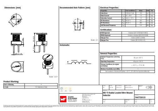
TDK EPCOS TP121C100K121M 电容器说明书
Dimensions: [mm]Scale - 2,5:17447720121A74477201217447720121T e m p e r a t u r eT T T 7447720121Cautions and Warnings:The following conditions apply to all goods within the product series of WE-TI of Würth Elektronik eiSos GmbH & Co. KG:General:•This electronic component was designed and manufactured for use in general electronic equipment.•Würth Elektronik must be asked for written approval (following the PPAP procedure) before incorporating the components into any equipment in fields such as military, aerospace, aviation, nuclear control, submarine, transportation (automotive control, train control, ship control), transportation signal, disaster prevention, medical, public information network, etc. where higher safety and reliability are especially required and/or if there is the possibility of direct damage or human injury.•Electronic components that will be used in safety-critical or high-reliability applications, should be pre-evaluated by the customer. •The component is designed and manufactured to be used within the datasheet specified values. If the usage and operation conditions specified in the datasheet are not met, the wire insulation may be damaged or dissolved.•Do not drop or impact the components, the component may be damaged.•Würth Elektronik products are qualified according to international standards, which are listed in each product reliability report. Würth Elektronik does not warrant any customer qualified product characteristics beyond Würth Elektroniks’ specifications, for its validity and sustainability over time.•The customer is responsible for the functionality of their own products. All technical specifications for standard products also apply to customer specific products.Product specific:Soldering:•The solder profile must comply with the technical product specifications. All other profiles will void the warranty.•All other soldering methods are at the customers’ own risk.Cleaning and Washing:•Washing agents used during the production to clean the customer application might damage or change the characteristics of the wire insulation, marking or plating. Washing agents may have a negative effect on the long-term functionality of the product. Potting:•If the product is potted in the costumer application, the potting material might shrink or expand during and after hardening. Shrinking could lead to an incomplete seal, allowing contaminants into the core. Expansion could damage the components. We recommend a manual inspection after potting to avoid these effects. Storage Conditions:• A storage of Würth Elektronik products for longer than 12 months is not recommended. Within other effects, the terminals may suffer degradation, resulting in bad solderability. Therefore, all products shall be used within the period of 12 months based on the day of shipment.•Do not expose the components to direct sunlight.•The storage conditions in the original packaging are defined according to DIN EN 61760-2.•The storage conditions stated in the original packaging apply to the storage time and not to the transportation time of the components. Packaging:•The packaging specifications apply only to purchase orders comprising whole packaging units. If the ordered quantity exceeds or is lower than the specified packaging unit, packaging in accordance with the packaging specifications cannot be ensured. Handling:•Violation of the technical product specifications such as exceeding the nominal rated current will void the warranty.•Applying currents with audio-frequency signals might result in audible noise due to the magnetostrictive material properties. •Due to heavy weight of the components, strong forces and high accelerations might have the effect to damage the electrical connection or to harm the circuit board and will void the warranty.•Please be aware that products provided in bulk packaging may get bent and might lead to derivations from the mechanical manufacturing tolerances mentioned in our datasheet, which is not considered to be a material defect.•The temperature rise of the component must be taken into consideration. The operating temperature is comprised of ambient temperature and temperature rise of the component.The operating temperature of the component shall not exceed the maximum temperature specified.These cautions and warnings comply with the state of the scientific and technical knowledge and are believed to be accurate and reliable.However, no responsibility is assumed for inaccuracies or incompleteness.Würth Elektronik eiSos GmbH & Co. KGEMC & Inductive SolutionsMax-Eyth-Str. 174638 WaldenburgGermanyCHECKED REVISION DATE (YYYY-MM-DD)GENERAL TOLERANCE PROJECTIONMETHODTRi001.0002019-01-24DIN ISO 2768-1mDESCRIPTIONWE-TI Radial Leaded Wire WoundInductor ORDER CODE7447720121SIZE/TYPE BUSINESS UNIT STATUS PAGEImportant NotesThe following conditions apply to all goods within the product range of Würth Elektronik eiSos GmbH & Co. KG:1. General Customer ResponsibilitySome goods within the product range of Würth Elektronik eiSos GmbH & Co. KG contain statements regarding general suitability for certain application areas. These statements about suitability are based on our knowledge and experience of typical requirements concerning the areas, serve as general guidance and cannot be estimated as binding statements about the suitability for a customer application. The responsibility for the applicability and use in a particular customer design is always solely within the authority of the customer. Due to this fact it is up to the customer to evaluate, where appropriate to investigate and decide whether the device with the specific product characteristics described in the product specification is valid and suitable for the respective customer application or not.2. Customer Responsibility related to Specific, in particular Safety-Relevant ApplicationsIt has to be clearly pointed out that the possibility of a malfunction of electronic components or failure before the end of the usual lifetime cannot be completely eliminated in the current state of the art, even if the products are operated within the range of the specifications.In certain customer applications requiring a very high level of safety and especially in customer applications in which the malfunction or failure of an electronic component could endanger human life or health it must be ensured by most advanced technological aid of suitable design of the customer application that no injury or damage is caused to third parties in the event of malfunction or failure of an electronic component. Therefore, customer is cautioned to verify that data sheets are current before placing orders. The current data sheets can be downloaded at .3. Best Care and AttentionAny product-specific notes, cautions and warnings must be strictly observed. Any disregard will result in the loss of warranty.4. Customer Support for Product SpecificationsSome products within the product range may contain substances which are subject to restrictions in certain jurisdictions in order to serve specific technical requirements. Necessary information is available on request. In this case the field sales engineer or the internal sales person in charge should be contacted who will be happy to support in this matter.5. Product R&DDue to constant product improvement product specifications may change from time to time. As a standard reporting procedure of the Product Change Notification (PCN) according to the JEDEC-Standard inform about minor and major changes. In case of further queries regarding the PCN, the field sales engineer or the internal sales person in charge should be contacted. The basic responsibility of the customer as per Section 1 and 2 remains unaffected.6. Product Life CycleDue to technical progress and economical evaluation we also reserve the right to discontinue production and delivery of products. As a standard reporting procedure of the Product Termination Notification (PTN) according to the JEDEC-Standard we will inform at an early stage about inevitable product discontinuance. According to this we cannot guarantee that all products within our product range will always be available. Therefore it needs to be verified with the field sales engineer or the internal sales person in charge about the current product availability expectancy before or when the product for application design-in disposal is considered. The approach named above does not apply in the case of individual agreements deviating from the foregoing for customer-specific products.7. Property RightsAll the rights for contractual products produced by Würth Elektronik eiSos GmbH & Co. KG on the basis of ideas, development contracts as well as models or templates that are subject to copyright, patent or commercial protection supplied to the customer will remain with Würth Elektronik eiSos GmbH & Co. KG. Würth Elektronik eiSos GmbH & Co. KG does not warrant or represent that any license, either expressed or implied, is granted under any patent right, copyright, mask work right, or other intellectual property right relating to any combination, application, or process in which Würth Elektronik eiSos GmbH & Co. KG components or services are used.8. General Terms and ConditionsUnless otherwise agreed in individual contracts, all orders are subject to the current version of the “General Terms and Conditions of Würth Elektronik eiSos Group”, last version available at .Würth Elektronik eiSos GmbH & Co. KGEMC & Inductive SolutionsMax-Eyth-Str. 174638 WaldenburgGermanyCHECKED REVISION DATE (YYYY-MM-DD)GENERAL TOLERANCE PROJECTIONMETHODTRi001.0002019-01-24DIN ISO 2768-1mDESCRIPTIONWE-TI Radial Leaded Wire WoundInductor ORDER CODE7447720121SIZE/TYPE BUSINESS UNIT STATUS PAGE。
迈信电气 EP1C EP1C PLUS EP3E 伺服系统 产品说明书

EP系列伺服系统EP1C通用伺服驱动器EP1C Plus高速高精伺服驱动器EP3E以太网总线伺服驱动器M/G系列交流永磁伺服电机专注伺服控制Since1998公司简介company profile武汉迈信电气技术有限公司于2004年成立于湖北省武汉市东湖高新技术开发区,公司自成立以来,一直致力于在工业自动化等领域为客户提供先进的产品和一流的服务。
全数字式交流伺服驱动器和交流伺服电机是武汉迈信电气技术有限公司的核心产品。
凭借多年的持续努力和技术团队20多年的技术积累和创新,公司现在已成为国内同行业技术和市场领先企业。
目前,武汉迈信电气技术有限公司的交流永磁伺服电机及驱动器已得到越来越多的客户认同和选用,并广泛应用于数控机床、纺织机械、包装机械、印刷机械、切割机、打标机、工业机器人等众多工业自动化领域,产品远销东南亚、印度、南非、俄罗斯、巴西等国家和地区。
产品伺服驱动器EP1C 全功率段通用型伺服驱动器:电压AC220V/380V,功率0.1kW~15kW。
EP1C Plus 高速高精伺服驱动器:电压AC220V/380V,功率0.1kW~15kW,支持23位串行编码器。
EP3E 工业实时以太网总线伺服驱动器:电压AC220V/380V,功率0.1kW~15kW。
伺服电机MS系列:中小惯量,高转速,高加减速,旋转伺服电机,转矩范围为0.32N·m~14.3N·m。
MA系列:中小惯量,中转速,小电流,旋转伺服电机,转矩范围为4.0N·m~48.0N·m。
GS系列:高惯量,高转速,旋转伺服电机,转矩范围为0.64N·m~15.0N·m。
GA系列:高惯量,中转速,旋转伺服电机,转矩范围为4.0N·m~15.0N·m。
MN系列:超小惯量,高动态性能,旋转伺服电机,转矩范围为1.0N·m~334.3N·m。
GK系列:低电压,中小惯量,高转速,旋转伺服电机,转矩范围为0.32N·m~2.39N·m。
EP3C25Q240C8中文资料(Altera)中文数据手册「EasyDatasheet - 矽搜」

—
1.71 1.8 1.89
V
—
1.425 1.5 1.575 V
电源电压为输出缓冲器,1.2-V
手术
—
1.14 1.2 1.26
V
VCCA (3)
VCCD_PLL (3) VI VO
供应(模拟)电压PLL
调节器
供应(数字)电压PLL
输入电压 输出电压
TJ
工作结温
tRAMP IDiode
电源斜坡时间
电源电压为输出缓冲器,3.3-V
手术
—
1.15 1.2 1.25
V
—
3.135 3.3 3.465 V
电源电压为输出缓冲器,3.0-V
手术
—
2.85
3
3.15
V
VCCIO (3), (4)
电源电压为输出缓冲器,2.5-V
手术
电源电压为输出缓冲器,1.8-V
手术
电源电压为输出缓冲器,1.5-V
手术
—
2.375 2.5 2.625 V
直流电流幅度
当启用PCI-钳位二极管
—
— — —
对于商业用途 工业用 对于扩展温度 对于汽车使用 标准上电复位
(POR) (5) 快速POR (6)
—
2.375 2.5 2.625 V
1.15 1.2 1.25
V
–0.5 —
3.6
V
0
—
VCCIO
V
0
—
85
°C
–40 — 100 °C
–40 — 125 °C
表1-4 列出I / O引脚泄漏 目前Cyclone III器件.
f
有关功耗估算工具更多信息 ,请参
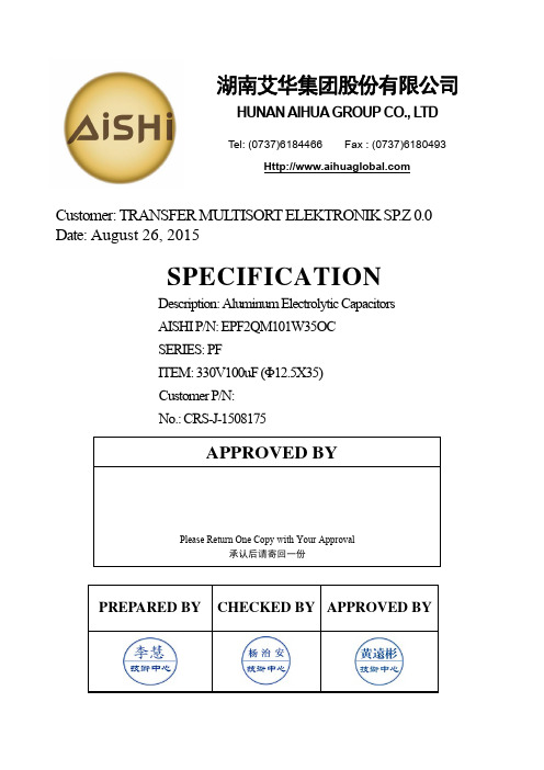
湖南艾华集团股份有限公司产品说明书:金属电容器
PREPARED BY CHECKED BY APPROVED BYCustomer: TRANSFER MUL TISORT ELEKTRONIK SP .Z 0.0 Date: August 26, 2015SPECIFICATIONDescription: Aluminum Electrolytic Capacitors AISHI P/N: EPF2QM101W35OC SERIES: PFITEM: 330V100uF (Φ12.5X35) Customer P/N:No.: CRS-J-1508175APPROVED BYPlease Return One Copy with Your Approval承认后请寄回一份湖南艾华集团股份有限公司HUNAN AIHUA GROUP CO., L TDTel: (0737)6184466 Fax : (0737)6180493版本更改原因更改内容 生效日期CRS-J-1508175新建新建2015-8-26CustomerTRANSFER MUL TISORT ELEKTRONIK SP .Z 0.0SERIESPF DATE 2015-8-26FIG-1TABLE-1No.Customer Part No.Aishi Part No.Capacitance(uF)Tolerance on Rated Capacitance(%)Rated V oltage (Vdc)Operating Temp. Range(℃)tan δ (120Hz)(Max)Leakage Current (uA) (5min.)Endurance at 55℃(Hours)Dimensions (mm)Appearance Drawing No. D ΦL αd F F11 EPF2QM101W35OC 100 ±20 330 -25~+55 0.06 100 5000 12.53520.6 5.0/FIG-1F ±0.5PVCL+ α MAX 15 MIN4MIN¢d±0.05D+0.5 MAX1.概述SCOPE本承认书规定了PF 系列径向引线引出铝电解电容器的技术规范,本技术规范条文解释权归本公司所有。
人民电器 创领系列选型手册 RDM3系列塑料外壳式断路器 产品资料说明书

PEOPLE ELECTRICSELECTIONGUI D E创领系列选型手册人民电器集团是人民控股集团全资公司,中国500强企业之一,始创于1986年。
人民电器集团以工业电器为核心产业,拥有浙江、上海、南昌、抚州、枣庄、合肥六大制造基地、35家全资子公司150家控股成员企业、1500多家加工协作企业和5000多家销售公司。
产品畅销全球125个国家和地区,广泛应用于浦东机场、京沪高铁、三峡水电、北京地铁、奥运场馆南水北调、青藏铁路、嫦娥探月工程、越南太安水电枢纽等国内外重大工程项目,位居世界机械企业500强前列。
2023年,经世界品牌实验室测评,品牌价值788.15亿。
Contents0407101217RDB3-63系列小型断路器RDB3LE 系列剩余电流动作断路器RDB3G-125系列隔离开关RDM3系列塑料外壳式断路器RDM3L 系列漏电断路器/04选型指南产品概述RDB3-63小型断路器(以下简称断路器),主要用于交流50Hz(或60Hz)额定工作电压至AC400V 额定电流至63A 额定短路分断能力不超过6000A 的保护配电线路中,作为线路不频繁接通、分断和转换之用,具有过载、短路保护功能。
同时具有强大的辅助功能模块,如辅助触点、带报警指示触点、分励脱扣器、欠压脱扣器、远程脱扣控制等模块。
产品符合:GB/T 10963.1标准。
,,,正常工作条件和安装条件□ 周围空气温度上限不超过+40℃,下限不低于-5℃,且24h 平均温度不超过+35℃;□ 安装地点海拔高度应不超过2000m □ 大气相对湿度在周围空气温度为+40℃时不超过50%,在较低温度下允许有较高的相对湿度;例如在+20℃时达90%。
对由于温度变化偶尔产生在产品上的凝露应采取特殊的措施□ 污染等级:2级□ 安装条件:安装在无显著冲击,振动的场所,无危险(爆炸)的介质中□ 安装方式:采用TH35-7.5安装轨安装□ 安装类别:Ⅱ、Ⅲ级。
EP3C16F484C6中文资料(Altera)中文数据手册「EasyDatasheet - 矽搜」

芯片中文手册,看全文,戳
1–2
电气特性
1
超出所列条件
表1-1 对器件造成永久性损坏.
此外,在延长时间周期绝对最大额定值设备操作具有设备不利影响.
表 1-1. Cyclone III器件绝对最大额定值
符
参数
VCCINT VCCIO
VCCA
电源电压为内部逻辑
电源电压为输出缓冲器
电源电压(模拟),用于锁相环 (PLL)调节器
Min –0.5 –0.5 –0.5 –0.5 –0.5 –25 —
— –65 –40
最大允许过冲或冲电压
在转换过程中,输入信号可以过冲到中列出电压 冲至-2.0 V电流小于100mA幅度和周期小于20纳秒短.
表1-2 列出所允许最大输入电压过冲和 过冲电压作为在装置寿命百分比持续时间. 允许最大过冲持续时间被指定为高时间比设备寿命百分比.
运行条件
当Cyclone III器件在一个系统中实现,它们是根据一组定义参数分级.为防护持 Cyclone III器件中最高性能和可靠性,系统设计人员必须考虑本文件中操 作要求. Cyclone III器件提供商用,工业和汽车级版本.商业设备在-6(最 快),-7和-8速度等级提供.工业和汽车设备仅在-7速度年级课程.
V
—
3.135出缓冲器,3.0-V
手术
—
2.85
3
3.15
V
VCCIO (3), (4)
电源电压为输出缓冲器,2.5-V
手术
电源电压为输出缓冲器,1.8-V
手术
电源电压为输出缓冲器,1.5-V
手术
—
2.375 2.5 2.625 V
—
1.71 1.8 1.89
EP3C25Q240C8N中文资料(Altera)中文数据手册「EasyDatasheet - 矽搜」

手术
—
1.15 1.2 1.25
V
—
3.135 3.3 3.465 V
电源电压为输出缓冲器,3.0-V
手术
—
2.85
3
3.15
V
VCCIO (3), (4)
电源电压为输出缓冲器,2.5-V
手术
电源电压为输出缓冲器,1.8-V
手术
电源电压为输出缓冲器,1.5-V
手术
—
2.375 2.5 2.625 V
(4)所有输入缓冲器由在V驱动
供电.
(5)50-200毫秒之间POR时间标准POR范围.每个单独电源应达到在推荐工作范围 50毫秒.
3-9毫秒(6)POR时间,快速POR范围.每个单独电源应在3毫秒达到推荐工作范围内.
芯片中文手册,看全文,戳
第 1章: Cyclone III器件数据表
表1-2 列出所允许最大输入电压过冲和 过冲电压作为在装置寿命百分比持续时间. 允许最大过冲持续时间被指定为高时间比设备寿命百分比.
Max
Unit
1.8
V
3.9
V
3.75
V
1.8
V
3.95
V
40
mA
±2000
V
±500
V
150
°C
125
°C
表1-2 and
芯片中文手册,看全文,戳
芯片中文手册,看全文,戳
July 2012 CIII52001-3.5
CIII52001-3.5
1.Cyclone III器件数据表
本章介绍电气特性,开关特性,以及I / O
对Cyclone时机
迈信电气 EP1C Pro 伺服系统 选型指南说明书

资料编号2021.06.0701020304远程升级EP1C Pro全系列产品支持远程固件升级,方便后期维护。
接线简化·380V系列驱动器省去外部24V控制电源接线;·可选内置/外置制动电阻接口;·可选直流电抗器接口。
性能提升·支持四段共振陷波器;·支持低频振动抑制及中频振动抑制;·支持摩擦补偿、速度观测器及高阶控制等功能。
接口丰富·兼容5V差分及24V单端脉冲指令输入;·支持11个可编程DI及5个可编程DO;·支持差分及单端ABZ反馈输出。
新一代EP1C Pro系列伺服驱动器,延续了EP1C系列的外观风格,采用全新的ARM构架CORTEX M4硬件平台及更加优化的软件控制算法。
新增加速度观测器、模型追踪及摩擦补偿等功能,搭配兼容性更强的信号指令接口,可满足客户更多应用需求。
EP1C Pro高速高精伺服驱动器0.1kW~15.0kW数控系统运动控制器运动控制卡PLCEP1C Pro伺服电机脉冲控制ModbusCANopen05062kHz响应带宽/定位时间短至1ms速度响应频宽为2kHz。
基于位置前馈的高响应控制,能降低响应延迟,功能后,抑制装置振动装置末端有两种振动成分,EP1C Pro系列伺服驱动器可同时抑制装置末端的两种振动,可以带来更高的机械响应。
符号电压L 220V H380V3符号额定转矩符号额定转矩TL010.1kW TL020.2kW TL050.5kW TH060.6kW TH10 1.0kW TH15 1.5kW TH20 2.0kW TH30 3.0kW TH50 5.0kW TH757.5kW TH909.0kW TH11011.0kW TH15015.0kWTL080.8kW TL10 1.0kW TL15 1.5kW TL25 2.5kW TL35 3.5kW TL555.5kW4系列名伺服驱动器1系列名伺服驱动器2符号制动器E3串行式编码器5符号制动器S2DB44控制端口6符号规格M 支持Modbus C支持CANopen707警示标签符号机座号04040mm 06060mm 08080mm 110110mm 130130mm 180180mm1符号系列MS MS系列伺服电机MA MA系列伺服电机GS GS系列伺服电机GA GA系列伺服电机BS BS系列伺服电机BABA系列伺服电机2符号电压L 220V H380V3符号额定转速151500rpm 202000rpm 252500rpm 303000rpm5符号编码器脉冲数分辨率导线数F 标准增量式2500ppr 10,00015旋转变压器R 12bit 4,0967C 多圈绝对值17bit 131,07277M 多圏绝对值23bit 8,388,608D 5单圈绝对值17bit 131,0727P多圏绝对值25bit33,554,432B 5单圈绝对值23bit 8,388,6086符号制动器N 不配置Z配置失电制动器7符号规格O 圆轴(无键)A 闭口键C开口键8符号规格1默认值2客户自定义9注:40、60、80全系列电机标配“A”,M/G系列110、130、180电机标配“H”,B系列110、130、180电机标配“J”,订货时标配符号省略。
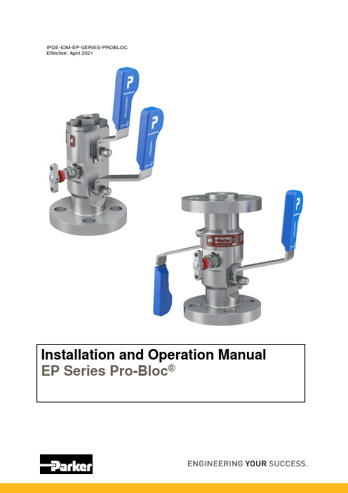
EP系列Pro-Bloc安装和操作手册说明书
IPDE-IOM-EP-SERIES-PROBLOCEffective: July 2018Effective: April 2021Installation and Operation Manual EP Series Pro-B loc®Parker HannifinParker Hannifin (IPDE)Riverside Road, Barnstaple, Devon, EX31 1NP United KingdomTelephone: (01271) 313131E-mail:*****************************.comIDENTIFICATION OF HAZARDSNEVER adjust valves under pressure.NEVER slacken or remove any valve parts under pressure.NEVER use any mechanical aids i.e. wrenches, extensions to operate handles.NEVER carry ball valves by the handle.NEVER obscure valve body marking.NEVER remove end connectors.NEVER use valves outside of rated operating conditions.INSTALLATIONWear suitable PPE before installation and follow appropriate site safety procedures.Before installation, ensure that all valves are in the closed position.Parker Pro-B loc® uses standard flange connections. For connection, please refer tothe appropriate installation standard for the flange specification in question.For non-flange end connection:•NPT: Use standard practice for NPT taper threads. Use an appropriate thread tape or sealant to prevent galling.•A-lok/CPI: See separate instruction sheet supplied with A-lok products.HANDLING AND STORAGEHandlingLarger sized Pro-B locs may be heavy. Ensure that local manual handling requirements are followed. Do not lift or carry by the operating handles, as this may cause damage.StorageThere is no specified shelf-life.Boxed products should be stored in a covered area, preferably indoors, and away from excessive moisture, heat, or airborne contaminants.The use of desiccant or corrosion inhibitors is not required during normal storage periods.OPERATIONBall Valve:To close: Operate the handle until it is at 90° from the valve body centreline.To open: Operate the handle until it is in line with the centreline of the body and reaches the stop pin. Movement is limited to 90° (except for vent ball valves) by a mechanical stop pin.Ball valves should always be fully open or fully closed. Do not leave in a mid-position.Three-way vent ball valves (red handle) have no firm centre-off position and are positioned visually. Needle Valve or Outside Screw and Yoke (vent):To close: Rotate handle clockwise until a stop is felt.To open: Fully rotate the handle anti-clockwise until a stop is felt.There are approximately three rotations between fully open and fully closed.Do not force rotation past the stop, as damage may occur. Maximum torque is 6NmFor anti-tamper designs only use the correct key for Parker manifolds.ISOLATE VALVE OPERATING POSITIONSISOLATE BALL VALVE IN CLOSED POSITIONISOLATE BALL VALVE IN OPEN POSITION.BALL VENT VALVE OPERATING POSITIONSVENT BALL VALVE IN CLOSED POSITIONVENT BALL VALVE IN OPEN POSITION.OPERATING SEQUENCEThese valves are primarily used for double isolation of an instrument, be that a gauge or a transmitter. The primary and secondary valves are in the open position during normal operating conditions allowing the process pressure to enter the gauge or transmitter to perform its function to give a pressure reading. The words Primary and Secondary are printed on the blue vinyl sleeves to aid identification.When the gauge or transmitter need removing for calibration in a workshop, the primary valve is closed to block the pressure, the secondary valve remains open and vent valve is opened to release the pressure within the instrument.The secondary and vent are then closed (the primary valves is already closed) and the instrument safely removed.The double block gives two isolations to prevent process escape while the instrument is removed. Once the instrument is calibrated or replaced with a new one it can be fitted back on top of the valve outlet and the primary and secondary valves opened again to allow pressure measurement to continue.It is possible to calibrate a pressure transmitter without removing it; this is in situation calibration commonly called “in-situ” calibration. To do this you follow the above procedure to vent the valve. Then a known pressure is pumped into the open vent, a handheld device is then connected to the back of the transmitter with electrical leads after removing the cover. If the known pressure from the pump agrees with the electrical reading from the transmitter it is in calibration and the measuring equipment removed, then the valves are returned to their operating positions.If however the readings do not agree, the measuring device has the ability to electronically change the reading to make it agree with the known pressure, this is done by turning a k nob clockwise or anticlockwise to change the reading of the transmitter up or down to suit, this is the “in-situ” calibration completed and the valves are again returned to their operating positions.Vent plug: The valve is shipped with a vent plug; loose or installed, as per the client’s requirements. While venting the valve this plug must be removed. The plug can be replaced for safety reasons or to prevent ingress of the environment. That is the operator’s decision and should be in their operating procedures. Parker are not responsible for this decision. It is suggested that PTFE tape or sealant is used to prevent galling of the threads.BALL VALVE HANDLE REMOVALBall Valve handle removal/reinstallationThe ball handle may be removed without under loading the packing. To remove the handle •Unscrew the top nut (Dome/handle locking nut)•Handle may be removed.To re-install the handle for valve operation:•Ensure shaft and nut threads are free from contaminants (including any used thread locker)•Replace handle•Apply Bondloc B272 or equivalent to nut threads ensuring good coverage.•Torque nut as follows:Pro-B loc Size:Top Nut Torque (Nm)10mm (EPBY), 15mm (EPBW), 20mm (EPBV) 23 Nm25mm (EPBV) 31 NmWARNING: Ensure handle is correctly installed before operation of valveTOP NUTSTOP PINHANDLESHAFTEEMUA Ball valveMAINTENANCEParker Pro-B locs are not user-serviceable, except for gland adjustment of the vent needle valve. Gland adjustment becomes necessary when the valve is visibly leaking through the spindle just below the operating handle, or prior to operation when no torque or resistance is evident when operating the valve handle. Adjustment to the gland can be carried out to prevent leakage. Replacement bonnets are available.H-series Needle Valve Gland Adjustment.CAUTION: Adjustment of the gland must be carried out at zero pressure1.Fully close the valve by turning the handle in a clockwise direction to stop lightly on seat(max. 2 Nm).2.Open the valve one full turn by rotating the handle in a counter-clockwise direction.3.Loosen gland lock nut.4.Tighten gland nut to 11 Nm5.Re-tighten gland lock nut to 25 NmH-Series Bonnet HANDLEGLAND NUT GLAND LOCKNUTPage 10 of 10 ECO-0364767 Rev: - Installation and Operation ManualEP Series Pro -B loc ®IPDE-IOM-EP-SERIES-PROBLOC Outside Screw and Yoke Valve Gland Adjustment. CAUTION: Adjustment of the gland must be carried out at zero pressure 1.Fully close the valve by turning the handle in a clockwise direction to stop lightly on seat (max. 2 Nm).2.Open the valve one full turn by rotating the handle in a counter-clockwise direction.3.The two bridge-nuts on either side of the spindle must be tightened evenly, keeping the bridge parallel to the body, to a torque of 5Nm.FURTHER INFORMATIONCv values:•10mm bore (PBY): 6.4•15mm bore (PBX): 15•20mm bore (PBW): 31•25mm bore (PBV): 39Needle valve sea t:•6mmCross hole drillings:•5mm HANDLEOutside Screw and Yoke (OS&Y) BonnetBRIDGE NUT(ONE EACHSIDE) BRIDGE。
电容器产品指南说明书

AP470NK500VAC AP1NK500VAC AP100NK500VAC AP2200NK500VAC AP1U5K500VAC AP2U2K500VACICW:Product guide:Radials:RNRT/RNRPFILM CAPACITORS Axials:AC Voltage ratedAX:Polypropylene250Vac ratedAP:Polypropylene500Vac&660Vac ratedPolypropylene axial wrap and end seal style capacitors offeringlow loss characteristics.Ideally suited to applications such asmains filters and where pulse performance is important.ICW:Product guide:Axials:AC Voltage rated:AX/APFILM CAPACITORS Full text descriptionBoth of these capacitors are constructed using the familiar‘wrap and end seal’method-wrapping the wound elements with heavy duty electrical tape which is wider than the elementand sealing the cavities formed at each end with epoxy resin.This style of manufacture resultsin a cost effective and volumetrically efficient component of the highest quality.The AX capacitors are suitable for pulse type circuits where high peak current handlingcapability is essential or at high frequency ac voltages where low loss is of prime consideration.The higher voltage handling capabilities of the AP range makes them ideally suited toapplications such as mains filtering and higher voltage pulse applications.Capacitance range AX:100nF to2µ2FAP:10nF to2µ2FT olerance±10%standard.Others by request Dissipation factor≤0.001@1KHz&20±3°CI nsulation resistance≥104MΩ-µF(C>330nF),≥3x10⁴MΩ(C≤330nF)@250Vac for AX and500Vdcfor AP and20±3°CRated voltage AX:250VacAP:500and660VacPulse performance See table.Ratings assume linear changeto/from rated voltage T emperature range-55to+100°CEnvironmental category55/100/56to EN60068-1(IEC68-1)Proof voltage test 1.5x rated voltage for30s.Not to be repeated Solderability BS2011:Part2.1T(IEC68-2-20)Solder Globule Method of test T aVibration EN60068-2-6(IEC68-2-6)T est Fc10to500Hz0.75mm or98m/s2 Bump EN60068-2-29(IEC68-2-29)T est Eb390m/s21000±10bumpsT echnical detailsICW:Product guide:Axials:AC Voltage rated:AX/APFILM CAPACITORSCAP(µF) 0.01 0.015 0.022 0.033 0.047 0.0680.1 0.15 0.22 0.33 0.470.681.001.52.2AX:250Vac/400VdcAP:500Vac/1000VdcAP:660Vac/1500VdcSize chart:Axials:AX&APAX Range:T erminations are tinned copper clad steel with a minimum length of30mmICW :Product guide :Axials :AC Voltage rated :AX /APFILM CAPACITORSPulse performanceRated voltage (Vdc)Body length250V 500V 660V (mm)AXAPAP191502910080100465070Maximum rates of change of Voltage dV/dt (V/µSFigures quoted in the chart above assume linear charge/discharge to /from rated voltage.When applied voltage (V A )is less than the rated voltage (V R )the rating may be increased by a factor V R /V A .OutlinedimensionsICW:Product guide:Axials:AC Voltage rated:AX/APFILM CAPACITORSAX100nK250VAX2µ2K250VCap Value µF for C≥IµF nF for C<IµFT oleranceM=±20%K=±10%J=±5%G=±2%†F=±1%†RatedVoltage acAP150nJ 660VAP2µ2K500VCap ValueµF for C≥IµFnF for C<IµFT oleranceM=±20%K=±10%J=±5%G=±2%†F=±1%†Rated Voltage ac†subject to availabilityOrdering detailsContact detailsIndustrial Capacitors(Wrexham)LtdMiners Road Llay Wrexham North Wales LL120PJT elephone44(0)1978853805Facsimile44(0)1978853785 Web Email***************.ukAP470NK500VAC AP1NK500VAC AP100NK500VAC AP2200NK500VAC AP1U5K500VAC AP2U2K500VAC。
许继低压电器智能电容器选型手册
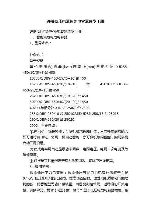
许继低压电器智能电容器选型手册许继低压电器智能电容器选型手册一、智能集成电力电容器1、型号命名:补偿方式型号规格单位电压(V)容量(kvar)高度H(mm)三相共补XJDBS-450/10/(5+5)台45010235XJDBS-450/15/(5+10)台45015235XJDBS-450/20/(10+10)台45020235XJDBS-450/25/(10+15)台45025290XJDBS-450/30/(10+20)台45030290XJDBS-450/40/(20+20)台45040290单相分补XJDBF-250/5台2505235XJDBF-250/10台25010235XJDBF-250/15台25015290XJDBF-250/20台250202902、主要特点:①.体积小、安装简便,可随机就地智能补偿,只需补接信号输入即可进行自动切。
②.可一机自动智能,亦可多机联网智能,实现多机自动联网投运。
③.集成电容可自动显示功率因数、电网电压、电网二次电流及故障信息等。
④.可根据实际情况设定投入功率因数、切除电压设定等。
3、适用范围:智能低压电力电容器(智能低压节能电力电容补偿装置)是0.4KW 低压配电网降低线损、提高功率因数、改善电能质量和节能降耗的新一代智能型无功补偿装置。
由智能测控单元、过零投切开关电路、保护单元、两台(△型)或一台(Y 型)低压电力电容器构成。
集成了现代测控,电力电子,网络通讯,自动化控制,电力电容器等先进技术。
改变了传统无功补偿装置落后的控制器技术和落后的机械式接触器或机电一体化开关作为投切电容器的投切技术,改变了传统无功补偿装置体积庞大和笨重的结构模式,具有补偿效果更好体积更小,功耗更低,价格更廉,节约成本更多,使用更加灵活,维护更加方便,使用寿命更长,可靠更高的特点,适应了现代电网对无功补偿的更高要求。
4、外形及安装尺寸:产品代号补偿方式:S -三相补偿;F -分相补偿额定电压(V )额定容量(kvar )第一路容量第二路容量企业代号5、工作条件:使用条件:海拔2000米以下,环境温度-25℃—+50℃;相对湿度≤90%(20℃)额定电压:250VAC50Hz额定容量:共补5-40kvar,分补5-20kvar电容允差:-5—+10%最高允许过压:110%额定电压6、电气接线原理简图:Y型电容接法△电容接法产品与电源端的连接导线规格:一般情况,单台总容量为30kvar 以上的共补和总容量为20kvar分补电容器,应采用标准16mm2截面积的多芯铜导线,其余规格采用标准10mm2截面积的多芯铜导线。
电容器基础知识详细介绍以及选型指南
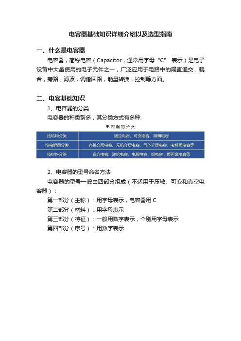
电容器基础知识详细介绍以及选型指南一、什么是电容器电容器,简称电容(Capacitor,通常用字母“C” 表示)是电子设备中大量使用的电子元件之一,广泛应用于电路中的隔直通交,耦合,旁路,滤波,调谐回路,能量转换,控制等方面。
二、电容基础知识1、电容器的分类电容器的种类繁多,其分类方式有多种:2、电容器的型号命名方法电容器的型号一般由四部分组成(不适用于压敏、可变和真空电容器):第一部分(主称):用字母表示,电容器用C第二部分(材料):用字母表示第三部分(特征):一般用数字表示,个别用字母表示第四部分(序号):用数字表示3、主要性能指标(1)标称电容量电容器上标有的电容数是电容器的标称容量。
电容的基本单位是法拉,简称法(F)。
但实际上,法拉是一个很不常用的单位,因为电容器的容量往往比1法拉小得多,常用的电容单位有微法(μF)、纳法(nF)和皮法(pF)。
它们的关系是:1F=1000mF;1mF=1000μF;1μF=1000nF;1nF=1000pF一般情况,电容器上都直接写出其容量,也有用数字来标志容量的。
通常在容量小于10000pF 的时候,用pF做单位,大于10000pF 的时候,用uF 做单位。
为了简便起见,大于 100pF 而小于 1uF 的电容常常不注单位。
没有小数点的,它的单位是pF,有小数点的,它的单位是 uF。
如有的电容上标有“332”(3300pF)三位有效数字,左起两位给出电容量的第一、二位数字,而第三位数字则表示在后加0 的个数,单位是 pF。
(2)允许误差电容器实际电容量与标称电容量的偏差称误差,在允许的偏差范围内称精度。
(3)额定电压在规定的工作温度范围内,电容器长期可靠地工作,它能承受的最高直流电压有效值,就是电容器的耐压,也叫做电容器的直流工作电压,一般直接标注在电容器外壳上。
如果在交流电路中,要注意所加的交流电压最高不能超过电容器的直流工作电压值。
常用的固定电容工作电压有:6.3V、10V、16V、25V、35V 、50V、63V、100V、2500V、400V、500V、630V(4)绝缘电阻直流电压加在电容上,并产生漏电电流,两者之比称为绝缘电阻。
HCCCAP EDLCs 超级电容规格书.pdf_1705701576.0406442说明书
HCCCAP EDLCsSPECIFICATION HCCCAP超级电容规格书【PRODUCT】产品:HCCCAP EDLCs【MODEL】型号:HCAP-D5R5255-F北京合众汇能科技有限公司HCC ENERGY TECH.Co.,LTD.TEL:+86-10-82897371email:*******************1.适用范围Scope本产品规格书对产品的性能,测试方法进行了规范,作为技术确认的参照。
数据参数仅作参考,不同批次与不同时间生产的实际产品参数可能会有所变化,以实际收到的产品为准,确切参数请及时向厂家核实。
This specification describes,the product property and test method,and should serve as the reference for technical assurance.These data is only for reference,actual product data in different batches and different times may vary,with the actual receipt of the product as a prospective,exact parameters,please promptly to the manufacturers to verify.2.一般特性General Specifications1)产品性能Features●高能量密度Ultra High Energy Density●长寿命Long Usage Life●高低温性能Excellent Performance at High and Low Temperatures●环保Environmental Friendly●免维护Maintenance Free2)产品应用范围Typical Applications●智能电网及其它配套设备Smart grid and other ancillary equipment●智能三表Intelligent Three-ammeters●集中器Concentrator●故障指示器Fault Indicator●混合动力汽车HEV/EV●太阳能/风能Solar/Wind energy●电机启动Motor drive●后备电源Memory Back up Batteries3)标准测试条件在标准大气压,温度5~35℃,相对湿度小于85%条件下进行测试;本规格书标准测试条件为标准大气压,温度25℃,相对湿度小于60%。
力创 电测控产品综合选型手册.pdf说明书
综合选型手册让计量更准确 使节能更智慧山东力创科技股份有限公司从成立之初,就一直致力于电测控类产品的研发和销售,至今已经有将近20年的历史。
20年来,力创人累计推出了上千种型号的电测类产品,成功应用于油田、煤矿、建筑、电器、通信、航天等行业,为我国的电子测量技术进步做出了巨大的贡献,在行业内树立了良好的口碑。
力创人始终秉持着“自主创新、勇攀高峰”的精神,不断积累,不断创新,培养了一批稳定的、有经验的技术研发人才,在多个领域内,不断突破技术瓶颈,依靠多年的开发经验和深厚的技术积累,突破了一个个技术难点,不断为客户呈现出简单易用,性能可靠的产品,深受广大用户好评。
如果一个产品的质量为100分的话,那么99%都应该是由设计环节决定的。
力创人深知管理对产品质量的重要性,在研发系统建立起了标准化的研发流程,从项目立项、需求分析、方案制定、到技术实现、产品测试都制定了严格的评审标准。
产品开发者对产品的全生命周期进行管理,不断完善、更新迭代,使产品越来越适合市场需要,越来越方便实用。
在做好研发管理的同时,力创人还非常注重制造管理,以做好那剩下的1%。
力创科技历经多年的发展,建立了非常完善的生产管理制度和流程。
产品从研发样品经纠偏测试完成以后,进入生产制造环节。
其中第一个环节是产品工程部,该部门先小批量试制一批产品,以了解这个产品的生产制造难点。
完全掌握产品的生产环节后,则把产品分解成一个个简单工序,并为每个工序制定标准作业指导书。
生产工人按照作业指导书进行生产,质检工人按照标准作业指导书检验作业质量,并引入了全自动化贴片、焊接、检验设备,实现了零误差。
大大提高了质量水平和生产效率。
尽力将产品的每一个环节做得完美,为客户贡献可靠、易用、高质量的产品是力创人做产品的基本准则。
在如今瞬息万变的商业环境下,力创将始终坚持这一原则,为广大客户服务,助力客户发展。
不忘初心,方得始终,力创人简单的坚持,是为了自己的诺言,也是为了客户的梦想。
如何选择电容器
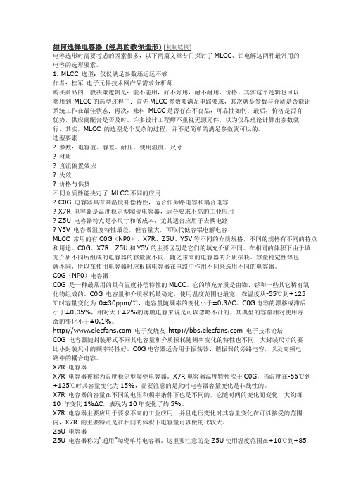
如何选择电容器(经典的教你选形)[复制链接]电容选形时需要考虑的因素很多,以下两篇文章专门探讨了MLCC、铝电解这两种最常用的电容的选形要素。
1. MLCC 选型:仅仅满足参数还远远不够作者:桂军电子元件技术网产品需求分析师购买商品的一般决策逻辑是:能不能用,好不好用,耐不耐用,价格。
其实这个逻辑也可以套用到MLCC的选型过程中:首先MLCC参数要满足电路要求,其次就是参数与介质是否能让系统工作在最佳状态;再次,来料MLCC是否存在不良品,可靠性如何;最后,价格是否有优势,供应商配合是否及时。
许多设计工程师不重视无源元件,以为仅靠理论计算出参数就行,其实,MLCC 的选型是个复杂的过程,并不是简单的满足参数就可以的。
选型要素? 参数:电容值、容差、耐压、使用温度、尺寸? 材质? 直流偏置效应? 失效? 价格与供货不同介质性能决定了MLCC不同的应用? C0G 电容器具有高温度补偿特性,适合作旁路电容和耦合电容? X7R 电容器是温度稳定型陶瓷电容器,适合要求不高的工业应用? Z5U 电容器特点是小尺寸和低成本,尤其适合应用于去耦电路? Y5V 电容器温度特性最差,但容量大,可取代低容铝电解电容MLCC 常用的有C0G(NP0)、X7R、Z5U、Y5V等不同的介质规格,不同的规格有不同的特点和用途。
C0G、X7R、Z5U和Y5V的主要区别是它们的填充介质不同。
在相同的体积下由于填充介质不同所组成的电容器的容量就不同,随之带来的电容器的介质损耗、容量稳定性等也就不同,所以在使用电容器时应根据电容器在电路中作用不同来选用不同的电容器。
C0G(NP0)电容器C0G 是一种最常用的具有温度补偿特性的MLCC。
它的填充介质是由铷、钐和一些其它稀有氧化物组成的。
C0G 电容量和介质损耗最稳定,使用温度范围也最宽,在温度从-55℃到+125℃时容量变化为0±30ppm/℃,电容量随频率的变化小于±0.3ΔC。
EP-C系列电容器产品选型手册
EP-C系列电容器选型手册上海久创智能电气工程有限公司Shanghai Everpower Intelligent Electric Engineering CO.,Ltd公司简介上海久创智能电气工程有限公司(EverPower)是专业从事电能质量综合治理工程服务、高低压无功补偿设备、高低压电气成套设备、电力系统自动化等智能电网相关设备与系统的研发、生产、销售和技术服务的高新技术企业。
久创科技园(总部)位于上海市莘庄工业区。
公司长期致力于电网谐波治理、无功补偿和电力系统继电保护、自动化控制、计算机网络和软件等相关领域产品研发和应用。
公司在产品的长期研发过程中,立足于中国电网和自动化工程的运行要求和特点,始终保持与国外同行业公司的技术交流与合作,本着稳定、可靠的基本出发点不断更新我们的技术与设计理念,使我们的产品和技术与国际接轨,不仅满足中国电网及用户的各种运行要求和使用习惯,而且符合国际电力系统二次元件发展潮流。
公司在职员工200余人,70%以上为大学本科以上学历的专业技术人员,都是长期从事电力电子、继电保护、自动控制等领域的专业技术人才和产业开拓者。
公司具有专门的开发、生产、试验基地——久创科技园,同时,公司在北京、济南、兰州、太原、沈阳、重庆、郑州、合肥、银川、福州、武汉、乌鲁木齐、呼和浩特等地设有办事处及技术服务中心,产品基本覆盖了华北、华东、西南、西北、东北等地区。
公司建立了专业的产品研发实验室,所有产品均自主研发,并获得了国家颁布的专利、高新技术成果转化。
重点新产品等证书。
产品主要包括高低压谐波治理及动态补偿产品、高低压电气成套产品、变/配电自动化系统产品、电力仪表等。
公司产品被广泛应用于发电厂、变电站、配电室和终端用户,所有系列产品均按照国家有关标准委托国家检测中心对产品进行严格、系统、全面的测试和检测,ISO9001质量认证的通过,进一步确保了产品的高可靠性。
公司本着“精心设计、安全可靠、一流服务、高效快捷”的质量方针,凭借科学有序的管理模式、稳定可靠的产品质量、开拓创新的销售思路和及时完善的售前售后服务,不仅取得了良好的市场业绩,同时也得到了设计单位和用户的一致认可和信誉。
瓷介电容_风华高科规格书
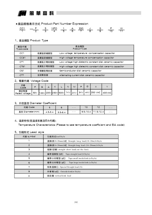
产品规格表示方式Product Part Number Expression1Product Type、产品类型CC11F 253NPO 415A 63307J 8S 9P 102Voltage Code、电压代码代码Code 额定电压Rated VoltageY 400VACF50V G100V A200V K250V L500V N1KV M2KVP3KV Q4KV 3Diameter Coefficient、片径直径代码直径Code Diameter(mm)65.5-6.4…………109.5-10.41211.5-12.4…………4(EIA )、温度特性见温度系数及代码:Temperature Characteristics (Please to see temperature coefficient and EIA code):5Lead style、引线形式代号symbol12345679W 11风华高科X250VAC54.5-5.4产品类型Product Type类型代号Typ e cod eLow voltage temperature compensation capacitor High voltage temperature compensation capacitorLow voltage high dielectric constant disk ceramic capacitor High voltage high dielectric constant disk ceramic capacitor Semiconductor disk ceramic capacitor Alternating current disk ceramic capacitor低压温度补偿型高压温度补偿型低压高介电常数型高压高介电常数型半导体型电容器交流电容器CC1CC81CT1CT81CS1CT7引线形式直脚长式直脚长式()编带直脚型(b式)编带小内弯型(a式)编带大内弯型(a式)特殊直脚S 外单弯(w式)前后翘lead Style(18-28mm)b Straight lon g lead (18~28m )b Style (16-20mm)b Straight long le ad (16~20mm)b Style straight short lead(cut the feet)Tape straight lead (b Style)Tape sm all inside kink (a Style)Tape large inside kink (a Sty le)()Special Straight lead (S)Outside kink(w Style)vertical kink lead短脚切脚6Lead Spacing、脚距7Standard capacitance、标称容量1R04R7100560821102-----注:标称容量以为单位,用位数字表示。
- 1、下载文档前请自行甄别文档内容的完整性,平台不提供额外的编辑、内容补充、找答案等附加服务。
- 2、"仅部分预览"的文档,不可在线预览部分如存在完整性等问题,可反馈申请退款(可完整预览的文档不适用该条件!)。
- 3、如文档侵犯您的权益,请联系客服反馈,我们会尽快为您处理(人工客服工作时间:9:00-18:30)。
EP-C系列电容器选型手册
上海久创智能电气工程有限公司Shanghai Everpower Intelligent Electric Engineering CO.,Ltd
公司简介
上海久创智能电气工程有限公司
(EverPower)是专业从事电能质量综合治
理工程服务、高低压无功补偿设备、高低压
电气成套设备、电力系统自动化等智能电网
相关设备与系统的研发、生产、销售和技术
服务的高新技术企业。
久创科技园(总部)
位于上海市莘庄工业区。
公司长期致力于电网谐波治理、无功补偿和电力系统继电保护、自动化控制、计算机网络和软件等相关领域产品研发和应用。
公司在产品的长期研发过程中,立足于中国电网和自动化工程的运行要求和特点,始终保持与国外同行业公司的技术交流与合作,本着稳定、可靠的基本出发点不断更新我们的技术与设计理念,使我们的产品和技术与国际接轨,不仅满足中国电网及用户的各种运行要求和使用习惯,而且符合国际电力系统二次元件发展潮流。
公司在职员工200余人,70%以上为大学本科以上学历的专业技术人员,都是长期从事电力电子、继电保护、自动控制等领域的专业技术人才和产业开拓者。
公司具有专门的开发、生产、试验基地——久创科技园,同时,公司在北京、济南、兰州、太原、沈阳、重庆、郑州、合肥、银川、福州、武汉、乌鲁木齐、呼和浩特等地设有办事处及技术服务中心,产品基本覆盖了华北、华东、西南、西北、东北等地区。
公司建立了专业的产品研发实验室,所有产品均自主研发,并获得了国家颁布的专利、高新技术成果转化。
重点新产品等证书。
产品主要包括高低压谐波治理及动态补偿产品、高低压电气成套产品、变/配电自动化系统产品、电力仪表等。
公司产品被广泛应用于发电厂、变电站、配电室和终端用户,所有系列产品均按照国家有关标准委托国家检测中心对产品进行严格、系统、全面的测试和检测,ISO9001质量认证的通过,进一步确保了产品的高可靠性。
公司本着“精心设计、安全可靠、一流服务、高效快捷”的质量方针,凭借科学有序的管理模式、稳定可靠的产品质量、开拓创新的销售思路和及时完善的售前售后服务,不仅取得了良好的市场业绩,同时也得到了设计单位和用户的一致认可和信誉。
在冶金、煤炭、矿上、化工、造纸、轨道交通、机械制造等行业取得了卓越的成绩,与各行业的的龙头企业建立了长期、稳定的合作关系。
“以用户的需求为根本,以用户的期望为目标,一切从用户出发”
是我们一贯秉承的思想和追求目标,也是我们对用户的承诺!
EP-C 圆柱型电容器
一、概述:
EP-C是最新一代低压自愈式电容器,主要用于提高功率因数和
改善电能质量,根据场合不同分为单相和三相。
EP-C电容器系列在
达到百级净化等级的环境中制造,在真空10~3Bar真空条件下对元件
进行加热同时进行灌注。
用这种方法可以使空气和湿气从电容内部排
出,从而避免了电极的氧化和局部的放电。
经过这一复杂的过程并进
行严格的出厂检验及质量考评,保证电容具有极好的稳定性和长使用
寿命。
二、型号含义:
相数(1:单相 3:三相)
容量(kVar)
额定电压(V)
干式电容器
企业代号
三、产品特点:
1、纯干式,可靠性高,寿命达到100000小时。
2、电容器顶部为防触电接线端子,结构新颖,便于接线及电容器之间组合,比如可以用15Kvar
组合成任意15的倍数的容量,用10Kvar和12Kvar的电容器组合成22Kvar的电容器。
3、外观漂亮,易于安装,铝质外壳,永不生锈。
4、电容芯子采用自愈式优质金属化聚丙烯薄膜。
5、电容器底部为M12或M16安装及接地螺栓。
四、技术参数:
电压范围:230~525V 根据用户需求可达2000V
额定容量:5~30kVar
温度范围:-50℃~﹢65℃
最高允许湿度:90%
绝缘水平:3/-KV
最高海拔:2000m
标准:GB/T12747.1&2-2004
五、电容器的安全性:
自放电性能:电容器有内置的放电电阻,使得电容器从电网中断开时,在3分钟内电压降到50V 以下,不会对人员及其它设备和器件造成伤害。
绝缘性能:接线端与外壳间能承受3000VAC的电压,不会发生漏电。
防爆性能:电容器在出现故障时,不会发生燃烧或爆炸。
当电容器出现故障时,电容器只表现开路,自动从电网中断开。
六、主要规格型号尺寸:
额定电压为400VAC,频率为50HZ,三相角接自愈式并联电容器
★额定电压为450VAC,频率为50HZ,三相角接自愈式并联电容器
★额定电压为480VAC,频率为50HZ,三相角接自愈式并联电容器
★额定电压为525VAC
,频率为50HZ,三相角接自愈式并联电容器
★额定电压为400VAC,频率为50HZ,单相自愈式并联电容器
50HZ,单相自愈式并联电容器
★额定电压为450VAC,频率为
50HZ,单相自愈式并联电容器
七、产品尺寸图:
注:1、以上为常规选型电容器参数,若需要其他参数时请联系。
2、外形尺寸供参考,最终尺寸以合同为准。
3、以上均为常规设计选型如有特殊要求在订货时请注明。
2015.03版。
