纤维弯曲性能测量
钢纤维高强混凝土弯曲性能试验研究

证 钢纤维拌 和均 匀 , 先搅 拌除钢 纤维外 的其 他材料 ,
再 将 钢 纤 维 均 匀 撒 入 , 部 投 入 后 再 搅 拌 2m n 全 i。搅
铣削 型 、 切断 弓形 、 切波 纹 形 , 中 以铣削 型 钢纤 剪 其
收 稿 日期 :0 l— 3—1 21 O 4 作者 简 介 : 谢 丽 ( 9 6 ) 女 , 南 信 阳 人 , 师 , 事 建筑 结 构 工 程 的教 学 与 研 究 工作 。 17 一 , 河 讲 从
凝 土小 梁 的 弯 曲试 验 , 讨 了钢 纤 维 高 强 混凝 土 弯 曲 条 件下 的裂 缝 发 展 、 坏 形 态 以及 钢 纤 维 高 强 混 凝 土 小 梁 试 件 的 尺 寸 效 应 , 探 破
研 究 了钢 纤 维体 积 率 和 钢 纤 维类 型 对 钢纤 维高 强 混 凝 土抗 折 初 裂 强度 和 抗 折 极 限 强度 的影 响 。
浙 江建筑 , 2 第 8卷 , 5期 ,0 1年 5月 第 21
Z ein o s u t n,Vo. 8,No 5,Ma 0 h j g C n t ci a r o 12 . y2 1 1
钢 纤 维 高 强 混 凝 土 弯 曲性 能 试 验 研 究
Ex e i n a u y on Ben n p r me t l St d dig Beh vo fSt e a iro e l FierRen o c d Hih Sten t b if r e g — r g h Con r t cee
度钢纤 维混凝 土试 验方 法 的弯 曲性 能 , 已经 有 了较
多 的 试 验 研 究 和 理 论 分 析 , 在 大 量 实 际 工 程 中 得 并
到 了应用 。而 对于钢 纤 维 高强 混 凝 土 的弯 曲性 能 ,
中文版 ISO 178-2010

ISO 178-2010塑料——弯曲性能的测定1.范围1.1本国际标准规定了在特定条件下测定硬质(见3.12)和半硬质塑料弯曲性能的方法。
规定了标准试样尺寸,同时对适合使用的替代试样也提供了尺寸参数。
规定了试验速度范围。
1.2本标准用于在规定条件下研究试样弯曲特性,测定弯曲强度、弯曲模量和其他弯曲应力/应变关系。
本标准适用于两端自由支撑、中央加荷的试验(三点加载测试)。
1.3本标准适用于下列材料:——热塑性模塑、挤出铸造材料,包括填充和增强复合物;硬质热塑性板材;——热固性模塑材料,包括填充和增强复合物;热固性板材。
与ISO 10350-1[5]和ISO 10350-2[6]一致,本国际标准适用于测试以长度≤7.5 mm纤维增强的复合物。
对于纤维长度>7.5 mm的长纤维增强材料(层压材料)的测试,见ISO 14125[7]。
本标准通常不适用于硬质多孔材料和含有多孔材料的夹层结构材料。
对这些材料的测试,可采用ISO 1209-1[3]和/或ISO 1209-2[4]。
注:对于某些纺织纤维增强的塑料,最好采用四点弯曲试验,见ISO 14125。
1.4本方法中所用的试样可以是选定尺寸的模塑试样,用标准多用途试样中部机加工的试样(见ISO 20753),或者从成品或半成品入模塑件、挤出或浇铸板材经机加工的试样。
1.5本标准推荐了最佳试样尺寸。
用不同尺寸或不同条件制备的试样进行试验,其结果是不可比较的。
其他因素,如试验速度和试样的状态调节也会影响试验结果。
注:尤其是半结晶聚合物,由模塑条件决定的样品表层厚度会影响弯曲性能。
1.6本方法不适用于确定产品设计参数,但可用于材料测试和质量控制测试。
1.7对于表现出非线性应力/应变特性的材料,其弯曲性能只为公称值。
给出的计算公式都基于应力/应变为线性的假设,且对样品挠度小于厚度的情况下有效。
使用推荐的试样尺寸(80 mm X 10 mm X 4 mm),在传统的3.5%弯曲应变和跨距与厚度比L/h为16的情况下,挠度为1.5 h。
纤维卷曲度
纤维卷曲度概述纤维卷曲度是描述纤维结构形态的一个重要参数,用于衡量纤维的弯曲程度和卷曲程度。
纤维的卷曲度影响着纤维的柔软性、弹性和力学性能。
在纺织工业、材料科学、纤维技术等领域,纤维卷曲度的研究对于优化纤维的性能和开发新型纤维材料具有重要意义。
纤维卷曲度的定义纤维的卷曲度是指纤维的曲线形状和弯曲程度。
通常将纤维看作是一条二维曲线,卷曲度可以表示曲线弯曲程度的物理量。
常用的卷曲度量化方法有曲率半径、卷曲指数等。
曲率半径方法曲率半径是一种常用的描述曲线曲率的物理量。
对于纤维而言,曲率半径越小,纤维的卷曲程度越高。
纤维的曲率半径可以通过测量纤维在不同位置的弯曲半径来计算。
曲率半径的计算公式为:R = (1/k)其中,R为曲率半径,k为纤维在某点处的曲率。
曲率可以通过求曲线的二阶导数来计算。
曲率半径的测量可以利用光学显微镜观察纤维的形态变化。
通过对纤维图像的处理和分析,可以获得纤维曲率半径的分布。
卷曲指数方法卷曲指数是描述纤维卷曲程度的另一种常用方法。
卷曲指数定义为纤维的曲线长度与直线长度之比。
通过测量纤维的实际长度和直线长度,可以计算纤维的卷曲指数。
卷曲指数的计算公式为:C = (Lc / Ls)其中,C为卷曲指数,Lc为纤维的曲线长度,Ls为相同纤维的直线长度。
卷曲指数可以通过计算机辅助图像处理的方式来进行测量。
图像处理技术可以提取纤维的曲线轮廓,并计算曲线长度和直线长度,从而得到纤维的卷曲指数。
纤维卷曲度与性能的关系纤维的卷曲度对纤维的性能和应用具有重要影响。
卷曲度可以改变纤维的表面特性、力学性能、传热性能等。
1.表面特性:卷曲的纤维表面积相比直纹纤维更大,容易与其他物质接触和吸附。
这对于染色、吸湿和表面反应等纤维处理过程有重要影响。
2.力学性能:卷曲度增加可以提高纤维的柔软性和弯曲强度。
卷曲的纤维结构比直纹纤维更能适应外力应变,具有更好的拉伸性能和疲劳性能。
3.传热性能:卷曲的纤维结构具有更大的表面积和更多的空隙,对流体(如空气或水)的流动和热传导能力更好。
基于定点握持弯曲疲劳的高性能纤维弯曲疲劳性能表征
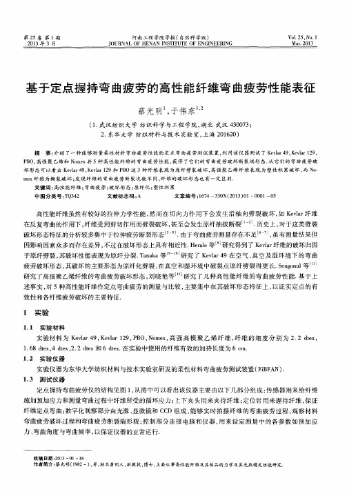
( 1 . 武汉纺织大学 纺织科学与工程学院 , 湖北 武汉 4 3 0 0 7 3 ; 2 . 东华 大 学 纺织材料 与技 术 实验 室 , 上海 2 0 1 6 2 0 )
摘 要: 介 绍 了一 种 能 够 测 量 柔 性 材 料 弯 曲疲 劳性 能的 定 点 弯 曲疲 劳测 试 装 置 , 利 用该 仪 器 测试 了 K e v l a r 4 9 , K e v l a r 1 2 9 ,
me x纤维为撕裂破坏 ; 发现纤维的弯曲疲劳断裂次数 不 同, 纤维 的破坏形 态也有一 定区别.
关键词 : 高性 能纤 维 ; 弯曲疲劳; 破坏形 态; 原 纤化 ; 塑性积 累 中 图分 类 号 : T Q 3 4 2 文献标志码 : A 文章 编 号 : 1 6 7 4—3 3 0 X( 2 0 1 3 ) O 1 — 0 0 0 1 —0 5
收 稿 日期 : 2 0 1 3一 叭 一l 8
作者简介 : 蔡 光明( 1 9 8 2 一) , 男, 湖北黄 冈人 , 副教授 , 博 士, 主要从事 高性能纤维及其制品的力学及其光热稳定性能研 究
ห้องสมุดไป่ตู้
第1 期
蔡光 明, 等: 基 于定点握持 弯曲疲劳的高性 能纤维弯曲疲劳性 能表征
・ 5・
[ 2 ] K i t a g a w a T, Mu r a s e H, Y a b u k i K .Mo r p h o l o g i c a l s t u d y o n P B O i f b r e [ J ] .P o l y m e r S c i e n c e , 1 9 9 8 ( B ) : 3 6— 3 9 . [ 3 ] B u n s e l A, He a r l J .A m e c h a n i s m o f f a t i g u e f a i l u r e i n n y l o n i f b r e s[ J ] . J o u r n a l o f Ma t e r i l a s S c i e n c e , 1 9 7 1 ( 6 ) : 1 3 0 3—1 3 l 1 . [ 4 ] H e r r e r a J , B u n s e l l A . M i c r o s t r u c t u r a l m e c h a n i s ms g o v e ni r n g t h e f a t i ue g f a i l u r e o f p o l y a m i d e 6 6 i f b r e s[ J ] .J o u na r l o f Ma t e i r a l s
纤维材料力学性能测试与模拟优化

纤维材料力学性能测试与模拟优化纤维材料是一类具有高强度、低密度和良好耐热性能的材料,广泛应用于航空航天、汽车工业、建筑和医疗领域。
为了确保纤维材料的可靠性和性能,对其力学性能进行测试与模拟优化是必不可少的。
本文将探讨纤维材料力学性能测试的方法以及如何通过模拟优化来提高其性能。
首先,纤维材料的力学性能测试是评估其材料特性和性能的关键步骤。
常用的力学性能测试方法包括拉伸测试、弯曲测试、压缩测试和剪切测试等。
这些测试可以帮助确定纤维材料的强度、刚度、断裂韧性和变形能力等重要性能指标。
拉伸测试是最常用的纤维材料力学性能测试方法之一。
它通过施加恒定的拉伸力来测量材料的应力-应变行为,从而评估材料的强度和延伸性能。
弯曲测试则是评估材料的抗弯性能,通过施加弯曲力使纤维材料发生弯曲,测量其变形和破坏情况,以评估其抗弯能力。
压缩测试是用来评估材料的抗压性能的方法。
它通过施加压缩力来测量纤维材料在压缩加载下的应力-应变行为。
通过这种测试,可以确定材料的抗压强度和峰值应变等参数,从而评估其抗压性能。
剪切测试是评估纤维材料抗剪性能的方法。
在剪切测试中,施加剪切力使材料发生剪切变形,并测量剪切应力和剪切应变,从而评估材料的剪切强度和刚度。
此外,模拟优化在纤维材料力学性能研究中也起着重要的作用。
通过数值模拟方法,可以对纤维材料的力学行为进行预测和优化。
有限元分析(FEA)是最常用的数值模拟方法之一,可以模拟纤维材料在不同加载条件下的应力分布和变形情况。
模拟优化能够为纤维材料的设计和制造提供重要的指导。
通过模拟优化,可以改变材料的结构和组织,从而调整其力学性能。
例如,可以通过改变纤维材料的层压顺序或纤维取向来提高其力学性能。
通过模拟优化,可以找到最优的纤维材料组合和结构设计,以提高其强度、刚度和韧性等性能。
总而言之,纤维材料的力学性能测试与模拟优化是确保其可靠性和性能的必要步骤。
通过准确测试纤维材料的力学性能,可以评估其强度、刚度和延展性等关键性能指标。
蚕丝纤维力学性能测试与优化
蚕丝纤维力学性能测试与优化蚕丝纤维是一种天然纤维,被认为是世界上最优秀的纤维之一。
它具有出色的力学性能,许多研究机构致力于测试和优化蚕丝纤维的力学性能。
本文将探讨蚕丝纤维力学性能的测试方法和优化途径。
力学性能是材料用于结构设计和工程应用的重要指标。
蚕丝纤维的力学性能包括强度、韧性、刚度和变形能力等。
这些性能可以通过一系列的测试来评估。
首先,强度是指蚕丝纤维抵抗外部应力的能力。
常用的测试方法包括拉伸测试和剪切测试。
拉伸测试可以测定蚕丝纤维的抗拉强度和断裂伸长率。
剪切测试可以测量蚕丝纤维的剪切强度和剪切模量。
这些测试可以帮助确定蚕丝纤维在不同工程应用中的强度需求。
韧性是衡量材料能够吸收能量的能力。
对蚕丝纤维进行韧性测试可以测量其断裂韧性和断裂缺口敏感性。
一种常用的测试方法是冲击测试,可以模拟蚕丝纤维在承受冲击载荷时的性能。
此外,疲劳测试也可以评估蚕丝纤维的韧性,该测试可以测定蚕丝纤维在重复应力循环中的耐久性。
刚度是指物体对外部应力的抵抗能力。
对于蚕丝纤维来说,刚度可以通过弯曲测试和压缩测试来测量。
弯曲测试可以测定蚕丝纤维的弯曲模量和弯曲强度。
压缩测试可以测量蚕丝纤维在受压载荷作用下的强度和刚度。
除了力学性能的测量,优化蚕丝纤维的力学性能也是非常重要的。
优化可以通过两种方式来实现:一种是改变蚕丝纤维的组织结构和纤维间的相互作用,另一种是利用表层修饰剂和增强材料。
在组织结构和相互作用方面,可以通过控制蚕丝纤维的加工条件来改变其结晶度和分子链的取向。
改变加工条件可以影响蚕丝纤维的力学性能,例如提高其强度和刚度。
此外,交联和纤维交织等处理方法也可以提高蚕丝纤维的力学性能。
在表层修饰剂和增强材料方面,可以使用聚合物涂层、纳米颗粒和纤维填料等方法来改善蚕丝纤维的力学性能。
这些修饰剂和增强材料可以增强纤维之间的相互粘合力,提高蚕丝纤维的强度和韧性。
总之,蚕丝纤维的力学性能是通过一系列测试来评估的。
了解蚕丝纤维的力学性能有助于设计结构和应用工程材料。
粘胶纤维 卷曲度
粘胶纤维卷曲度粘胶纤维凭借其独特的性能和广泛的应用领域,在纺织行业中扮演着重要的角色。
其中,粘胶纤维的卷曲度是决定其质量和特性的重要指标之一。
本文将探讨粘胶纤维卷曲度的定义、测试方法以及与纺织品加工的关系。
一、粘胶纤维卷曲度的定义粘胶纤维的卷曲度是指纤维的弯曲程度,通常通过纤维的曲率半径来衡量。
卷曲度越大,纤维越容易形成凹凸不平的表面,从而增加纤维与纤维之间的摩擦力,提高纤维的抗滑性和更好的结构稳定性。
二、粘胶纤维卷曲度的测试方法1. 曲率法曲率法是常用的测试粘胶纤维卷曲度的方法。
首先,采用显微镜放大纤维图像,然后使用专业图像处理软件进行纤维的曲率半径测量。
通过测量一段纤维上多个点的曲率半径并求取平均值,从而得到纤维的卷曲度。
2. 机械测试法机械测试法是利用专业的仪器设备进行测试。
采用拉伸装置拉伸纤维样本,同时记录样本在拉伸过程中的变形情况。
借助测试设备提供的数据分析,包括变形程度、曲率半径等,从而得到纤维的卷曲度。
三、粘胶纤维卷曲度与纺织品加工的关系粘胶纤维的卷曲度对纺织品加工和性能有着重要的影响。
1. 强度和韧性粘胶纤维的卷曲度影响纤维之间的接触面积和摩擦力,进而影响纤维的结合强度和韧性。
适当的卷曲度可以增加纤维间的接触面积和摩擦力,从而提高纤维的结合强度和韧性。
2. 纺纱性能粘胶纤维的卷曲度对纺纱工艺有着重要的影响。
适当的卷曲度可以提高纤维在纺纱过程中的牵引性和卷曲性,增加纤维间的交织程度,有利于纤维的均匀分布和纺纱质量的提高。
3. 织物外观粘胶纤维的卷曲度还与织物的外观品质密切相关。
适当的卷曲度可以增加织物的立体感和手感,提高织物的舒适度和附着性。
综上所述,粘胶纤维的卷曲度是一个重要的指标,对纤维的性能和纺织品加工有着重要的影响。
通过合理的测试方法和生产工艺控制,可以获得具有适当卷曲度的粘胶纤维,从而满足不同应用场景对纤维性能的需求,提高纺织品的质量和附加值。
ASTM C1609 C1609M-12纤维混凝土弯曲性能的标准试验方法(使用具有第三点荷载的梁)
Designation:C1609/C1609M–10Standard Test Method forFlexural Performance of Fiber-Reinforced Concrete(Using Beam With Third-Point Loading)1This standard is issued under thefixed designation C1609/C1609M;the number immediately following the designation indicates the year of original adoption or,in the case of revision,the year of last revision.A number in parentheses indicates the year of last reapproval.A superscript epsilon(´)indicates an editorial change since the last revision or reapproval.1.Scope*1.1This test method evaluates theflexural performance of fiber-reinforced concrete using parameters derived from the load-deflection curve obtained by testing a simply supported beam under third-point loading using a closed-loop,servo-controlled testing system.1.2This test method provides for the determination of first-peak and peak loads and the corresponding stresses calculated by inserting them in the formula for modulus of rupture given in Eq1.It also requires determination of residual loads at specified deflections,the corresponding residual strengths calculated by inserting them in the formula for modulus of rupture given in Eq1(see Note1).It provides for determination of specimen toughness based on the area under the load-deflection curve up to a prescribed deflection(see Note2)and the corresponding equivalentflexural strength ratio.N OTE1—Residual strength is not a true stress but an engineering stress computed using simple engineering bending theory for linear elastic materials and gross(uncracked)section properties.N OTE2—Specimen toughness expressed in terms of the area under the load-deflection curve is an indication of the energy absorption capability of the particular test specimen,and its magnitude depends directly on the geometry of the test specimen and the loading configuration.1.3This test method utilizes two preferred specimen sizes of100by100by350mm[4by4by14in.]tested on a300mm [12in.]span,or150by150by500mm[6by6by20in.] tested on a450mm[18in.]span.A specimen size different from the two preferred specimen sizes is permissible.1.4Units—The values stated in either SI units or inch-pound units are to be regarded separately as standard.The values stated in each system may not be exact equivalents; therefore,each system shall be used independently of the other. Combining values from the two systems may result in non-conformance with the standard.1.5This standard does not purport to address all of the safety concerns,if any,associated with its use.It is the responsibility of the user of this standard to establish appro-priate safety and health practices and determine the applica-bility of regulatory limitations prior to use.2.Referenced Documents2.1ASTM Standards:2C31/C31M Practice for Making and Curing Concrete Test Specimens in the FieldC42/C42M Test Method for Obtaining and Testing Drilled Cores and Sawed Beams of ConcreteC78Test Method for Flexural Strength of Concrete(Using Simple Beam with Third-Point Loading)C125Terminology Relating to Concrete and Concrete Ag-gregatesC172Practice for Sampling Freshly Mixed ConcreteC192/C192M Practice for Making and Curing Concrete Test Specimens in the LaboratoryC823Practice for Examination and Sampling of Hardened Concrete in ConstructionsC1140Practice for Preparing and Testing Specimens from Shotcrete Test Panels3.Terminology3.1Definitions—The terms used in this test method are defined in Terminology C125.3.2Definitions of Terms Specific to This Standard:3.2.1end-point deflection,n—the deflection value on the load-deflection curve equal to1⁄150of the span length,or a larger value as specified at the option of the specifier of tests.3.2.2first-peak load,P1,n—the load value at thefirst point on the load-deflection curve where the slope is zero.3.2.3first-peak deflection,d1,n—the net deflection value on the load-deflection curve atfirst-peak load.3.2.4first-peak strength f1,n—the stress value obtained when thefirst-peak load is inserted in the formula for modulus of rupture given in Eq1.3.2.5load-deflection curve,n—the plot of load versus net deflection of aflexural beam specimen loaded to the end-point deflection.1This test method is under the jurisdiction of ASTM Committee C09on Concrete and Concrete Aggregates and is the direct responsibility of SubcommitteeC09.42on Fiber-Reinforced Concrete.Current edition approved March1,2010.Published April2010.Originally approved st previous edition approved in2007as C1609/C1609M–07. DOI:10.1520/C1609_C1609M-10.2For referenced ASTM standards,visit the ASTM website,,or contact ASTM Customer Service at service@.For Annual Book of ASTM Standards volume information,refer to the standard’s Document Summary page on the ASTM website.*A Summary of Changes section appears at the end of this standard. Copyright©ASTM International,100Barr Harbor Drive PO Box C-700,West Conshohocken,Pennsylvania19428-2959,United States3.2.6net deflection ,n —the deflection measured at mid-span of a flexural beam specimen exclusive of any extraneous effects due to seating or twisting of the specimen on its supports or deformation of the support and loading system.3.2.7peak load,P P ,n —the maximum load on the load-deflection curve.3.2.8peak-load deflection,d P ,n —the net deflection value on the load-deflection curve at peak load.3.2.9peak strength,f P ,n —the stress value obtained when the peak load is inserted in the formula for modulus of rupture given by Eq 1.3.2.10D —nominal depth of the beam specimen in mm.N OTE 3—To simplify nomenclature,the nominal beam depth is shown in units of mm for both the SI and inch-pound version of this test method.3.2.11L —span length or distance between the supports.3.2.12residual load,P 600D ,n —the load value correspond-ing to a net deflection of L/600for a beam of nominal depth D.3.2.13residual load,P 150D ,n —the load value corresponding to a net deflection of L/150for a beam of nominal depth D.3.2.14residual strength,f 600D ,n —the stress value obtainedwhen the residual load P 600Dis inserted in the formula for modulus of rupture given in Eq 1.3.2.15residual strength,f 150D ,n —the stress value obtainedwhen the residual load P 150Dis inserted in the formula for modulus of rupture given in Eq 1.3.2.16specimen toughness,T 150D ,n —toughness of beam specimen of nominal depth D at a net deflection of L/150.3.2.17equivalent flexural strength ratio,R T ,150D,n —thevalue obtained when the specimen toughness T 150Dis inserted in Eq 3.N OTE 4—The equivalent flexural strength ratio is calculated as the ratio of the weighted equivalent load up to a net deflection of L/150over the first-peak load multiplied by 100.The R T ,150150value is equivalent to the R e,3value defined in the Technical Report No.34of the Concrete Society.34.Summary of Test Method4.1Molded or sawn beam specimens having a square cross-section of fiber-reinforced concrete are tested in flexure using a third-point loading arrangement similar to that speci-fied in Test Method C78but incorporating a closed-loop,servo-controlled testing system and roller supports that are free to rotate on their axes.Load and net deflection are monitored and recorded to an end-point deflection of at least 1⁄150of the span.Data are recorded and plotted by means of an X-Y plotter,or they are recorded digitally and subsequently used to plot a load-deflection curve.Points termed first-peak,peak,and residual loads at specified deflections are identified on the curve,and are used to calculate flexural performance param-eters.5.Significance and Use5.1The first-peak strength characterizes the flexural behav-ior of the fiber-reinforced concrete up to the onset of cracking,while residual strengths at specified deflections characterize theresidual capacity after cracking.Specimen toughness is a measure of the energy absorption capacity of the test specimen.The appropriateness of each parameter depends on the nature of the proposed application and the level of acceptable crack-ing and deflection serviceability.Fiber-reinforced concrete is influenced in different ways by the amount and type of fibers in the concrete.In some cases,fibers may increase the residual load and toughness capacity at specified deflections while producing a first-peak strength equal to or only slightly greater than the flexural strength of the concrete without fibers.In other cases,fibers may significantly increase the first-peak and peak strengths while affecting a relatively small increase in residual load capacity and specimen toughness at specified deflections.5.2The first-peak strength,peak strength,and residual strengths determined by this test method reflect the behavior of fiber-reinforced concrete under static flexural loading.The absolute values of energy absorption obtained in this test are of little direct relevance to the performance of fiber-reinforced concrete structures since they depend directly on the size and shape of the specimen and the loading arrangement.5.3The results of this test method may be used for com-paring the performance of various fiber-reinforced concrete mixtures or in research and development work.They may also be used to monitor concrete quality,to verify compliance with construction specifications,obtain flexural strength data on fiber-reinforced concrete members subject to pure bending,or to evaluate the quality of concrete in service.5.4The results of this standard test method are dependent on the size of the specimen.N OTE 5—The results obtained using one size molded specimen may not correspond to the performance of larger or smaller molded specimens,concrete in large structural units,or specimens sawn from such units.This difference may occur because the degree of preferential fiber alignment becomes more pronounced in molded specimens containing fibers that are relatively long compared with the cross-sectional dimensions of the mold.Moreover,structural members of significantly different thickness experi-ence different maximum crack widths for a given mid-span deflection with the result that fibers undergo different degrees of pull-out and extension.6.Apparatus6.1Testing Machine —The testing machine shall be capable of servo-controlled operation where the net deflection of the center of the beam is measured and used to control the rate of increase of deflection.Testing machines that use stroke dis-placement control or load control are not suitable for estab-lishing the portion of the load-deflection curve immediately after first-peak.The loading and specimen support system shall be capable of applying third-point loading to the specimen without eccentricity or torque.The fixtures specified in Test Method C78are suitable with the qualification that supporting rollers shall be able to rotate on their axes and shall not be placed in grooves or have other restraints that prevent their free rotation.6.2Deflection-Measuring Equipment —Devices such as electronic transducers or electronic deflection gages shall be located in a manner that ensures accurate determination of the net deflection at the mid-span exclusive of the effects of seating or twisting of the specimen on its supports.One acceptable3“Concrete Industrial Ground Floors—A Guide to Design and Construction,”Technical Report 34,3rd edition,Concrete Society,Slough,United Kingdom,2003.arrangement employs a rectangular jig,which surrounds the specimen and is clamped to it at mid-depth directly over the supports (Figs.1and 2).Two electronic displacement trans-ducers or similar digital or analog devices mounted on the jig at mid-span,one on each side,measure deflection through contact with appropriate brackets attached to the specimen.The average of the measurements represents the net deflection.6.3Data Recording System —An X-Y plotter coupled di-rectly to electronic outputs of load and deflection is an acceptable means of obtaining the relationship between load and net deflection—that is,the load-deflection curve.A data acquisition system capable of digitally recording and storing load and deflection data at a sampling frequency of at least 2.5Hz is an acceptable alternative.After a net deflection of L/900has been exceeded,it is permissible to decrease the data acquisition sampling and recording frequency to 1Hz.N OTE 6—For X-Y plotters,accurate determination of the area under the load-deflection curve and the loads corresponding to specified deflections is only possible when the scales chosen for load and deflection are reasonably large.A load scale chosen such that 25mm [1in.]corresponds to a flexural stress of the order of 1MPa [150psi],or no more than 20%of the estimated first-peak strength,is recommended.A recommended deflection scale is to use 25mm [1in.]to represent about 10%of the end-point deflection of 1⁄150of the span,which is 2mm [0.08in.]for a 350by 100by 100mm [14by 4by 4in.]specimen size,and 3mm [0.12in.]for a 500by 150by 150mm [20by 6by 6in.]specimen size.When data are digitally stored,the test parameters may be determined directly from the stored data or from a plot of the data.In the latter case,use a plot scale similar to that recommended for an X-Y plotter.7.Sampling,Test Specimens,and Test Units7.1General Requirements —The nominal maximum size of aggregate and cross-sectional dimensions of test specimens shall be in accordance with Practice C31/C31M or Practice C192/C192M when using molded specimens,or in accordance with Test Method C42/C42M when using sawn specimens,provided that the following requirements are satisfied:7.1.1The length of test specimens shall be at least 50mm [2in.]greater than three times the depth,and in any case not less than 350mm [14in.].The length of the test specimen shall not be more than two times the depth greater than the span.7.1.2The tolerances on the cross-section of the test speci-mens shall be within 62%.The test specimens shall have a square cross-section within these tolerances.7.1.3The width and depth of test specimens shall be at least three times the maximum fiber length.7.1.4When the specimen size is not large enough to meet all the requirements of 7.1-7.1.3,specimens of square cross-section large enough to meet the requirements shall be used.The three times maximum fiber length requirement for width and depth may be waived at the option of the specifier of tests to permit specimens with a width and depth of 150mm [6in.]when using fibers of length 50to 75mm [2to 3in.].N OTE 7—The results of tests on beams with relatively stiff fibers,such as steel fibers,longer than one-third the width and depth of the beam may not be comparable with test results of similar-sized beams with fibers shorter than one-third the width and depth because of preferential fiber alignment,and different size beams may not be comparable because of size effects.The degree of preferential fiber alignment may be less for fibers that are flexible enough to be bent by contact with aggregate particles or mold surfaces than for rigid fibers that remain straight during mixing and specimen preparation.7.2Freshly Mixed Concrete —Obtain samples of freshly mixed fiber-reinforced concrete for the preparation of test specimens in accordance with Practice C172.7.2.1Mold specimens in accordance with Practice C31/C31M or Practice C192/C192M ,except that consolidation shall be by external vibration.Consolidation may be consid-ered to be adequate when entrapped air voids are no longer observed rising to the surface of the specimen.Fill the mold in one layer by using a wide shovel or scoop parallel to the length of the mold to place the layer uniformly along the length of themold.FIG.1Arrangement to Obtain Net Deflection by Using Two Transducers Mounted on Rectangular Jig Clamped to Specimen DirectlyAboveSupportsN OTE 8—Make sure that the time of vibration is sufficient to ensure adequate consolidation,as fiber-reinforced concrete requires a longer vibration time than concrete without fibers,especially when the fiber concentration is relatively high.7.2.2When filling the mold,attempt to add an amount of concrete that will exactly fill the mold after consolidation.When screeding the top surface,continue external vibration to ensure that fibers do not protrude from the finished surface.7.2.3Curing shall be in accordance with Practice C31/C31M or Practice C192/C192M .7.3Hardened Concrete —Select samples of hardened fiber-reinforced concrete from structures in accordance with Practice C823.7.3.1Prepare and condition sawn specimens in accordance with Test Method C42/C42M .7.4Prepare specimens from shotcrete panels in accordance with Practice C1140.7.5Test Unit —Prepare and test at least three specimens from each sample of fresh or hardened concrete.8.Evaporation Control8.1When the time between removal of test specimens from a moist curing environment and the start of testing is likely to exceed 15min,minimize drying by covering with wet burlap,applying a curing compound,or by other appropriate tech-niques.9.Procedure9.1Molded or sawn specimens shall be turned on their side with respect to the position as cast before placing on the support system.Specimens representing shotcrete shall be loaded in the same direction as the specimen was shot.9.2Arrange the specimen and the loading system so that the specimen is loaded at the third points in accordance with TestMethod C78.The span length shall be three times the specimen depth or 300mm [12in.],whichever is greater.N OTE 9—If full contact cannot be reasonably assured between the specimen,the load-applying devices,and the supports before loading,grind the contact surfaces of the specimen so that full contact is achieved.Alternatively,use capping materials at the load or support points.9.3Operate the testing machine so that the net deflection of the specimen increases at a constant rate in accordance with Table 1.Up to a net deflection of L/900,the rate of increase of net deflection shall be in accordance with the second column of Table 1.For net deflection beyond L/900and up to the end point deflection,a higher rate of increase of net deflection is permitted in accordance with the third column of Table 1.When increasing the loading rate,the rate of increase of net deflection shall be increased in increments not exceeding 0.05mm/min [0.002in./min].Subsequent increases of the rate of increase of net deflection shall be at least 30s apart.Include the rate(s)of increase of net deflection in the test report.N OTE 10—First-peak deflection for third-point loading isestimatedFIG.2Arrangement to Obtain Net Deflection by Using Two Transducers Mounted on Jig Secured to Specimen Directly Above SupportsTABLE 1Rate of Increase in Net DeflectionBeam sizeAUp to net deflection of L/900Beyond net deflection of L/900100by 100by 350mm0.025to 0.075mm/min 0.05to 0.20mm/min [4by 4by 14in.][0.001to 0.003in./min][0.002to 0.008in./min]150by 150by 500mm0.035to 0.10mm/min 0.05to 0.30mm/min [6by 6by 20in.][0.0015to 0.004in./min][0.002to 0.012in.min]AThe initial loading rate up to deflection of L/900for other sizes and shapes of specimens shall be based on reaching the first-peak deflection 40to 100s after the start of the test.Beyond a net deflection of L/900,the rate of increase of net deflection shall not exceed 8times the initialrate.assuming linear-elastic behavior up tofirst peak from the equation:d1523P1L31296EI F11216d2~11µ!115L2Gwhere:d 1=thefirst peak deflection,mm[in.]P 1=thefirst-peak load,N[lbf]L=the span length,mm[in.]E=the estimated modulus of elasticity of the concrete,MPa[psi] I=the cross-sectional moment of inertia,mm4[in.4]d=the average depth of specimen at the fracture,as oriented for testing,mm[in.]andµ=Poisson’s ratioFor a Poisson’s ratio of0.20and a d to L ratio of1/3,the value of the portion of the equation in brackets is1.25.N OTE11—For a350by100by100mm[14by4by4in.]specimen size,the net deflection atfirst-peak load is approximately0.04mm [0.0016in.],and for a500by150by150mm[20by6by6in.]specimen size,it is approximately0.05mm[0.002].9.4If the rate of increase of net deflection cannot be controlled(see Note12)during the test,it is permitted to reduce the initial net deflection rate to50%of the limits in9.3 until a net deflection of L/900is reached.After a net deflection of L/900,the rate of increase of net deflection shall not exceed 8times the initial rate until the specified end-point deflection is reached.When increasing the loading rate,the rate of increase of net deflection shall be increased in increments not exceeding 0.05mm/min[0.002in./min].Subsequent increases of the rate of net deflection shall be at least30s apart.Include the rate(s) of increase of net deflection in the test report.N OTE12—The rate of increase of net deflection is out of control if a sudden acceleration of the net deflection of a beam occurs leading to a rate at least20times higher than the rate specified in9.3and9.4.The lower loading rate is permitted for brittle(higher strength)concretes to provide better control of the increase of net deflection immediately after the peak load.9.5When using deflection-measuring equipment for thefirst time,or after alterations or maintenance,confirm the reliability of the measured net deflection by comparing the measured deflection atfirst-peak load with the value estimated from the formula in Note10.9.6Unless otherwise required by the specifier of tests, terminate the test at a net deflection of1⁄150of the span.9.7Further testing to a greater end-point deflection shall be specified at the option of the specifier of tests,and shall be specified as the span divided by some whole number less than 150.9.8Make two measurements of the specimen depth and width adjacent to the fracture(one on each face of the specimen)to the nearest1mm[0.05in.]to determine the average depth and width.9.9Determine the position of the fracture by measuring the distance along the middle of the tension face from the fracture to the nearest point of support.9.10When the fracture occurs outside the middle third of the span,discard the results.10.Calculation10.1Values of load and deflection used in subsequent calculations shall be obtained from the load-deflection curve, or from stored digital data.10.2Determine thefirst-peak load as that value of load corresponding to thefirst point on the load-deflection curve where the slope is zero,that is,the load is a local maximum value.Determine the corresponding deflection value.See Figs. 3and4.N OTE13—Small ripples orfluctuations in the load-deflection curve due to electronic noise or mechanical vibration should not be confused with a definite change in the slope of the load-deflection curve in the vicinity of first peak load,particularly when the portion of the curve in question is magnified.10.3Calculate thefirst-peak strength using thefirst-peak load determined in10.2,the average specimen dimensions determined in9.8,and the following formula for modulus of rupture:f5PLbd2(1)where:f=the strength,MPa[psi],P=the load,N[lbf],L=the span length,mm[in.],b=the average width of the specimen at the fracture,as oriented for testing,mm[in.],andd=the average depth of the specimen at the fracture,as oriented for testing,mm[in.].10.3.1Record the number rounded to the nearest0.05MPa [5psi]as thefirst-peak strength,f1.10.4Determine the peak load as that value of load corre-sponding to the point on the load-deflection curve that corre-sponds to the greatest value of load obtained prior to reaching the end-point deflection.Determine the corresponding deflec-tion value.10.5Calculate the peak strength using the peak load deter-mined in10.4,the average specimen dimensions determined in 9.8,and Eq1.Record the number rounded to the nearest0.05 MPa[5psi]as the peak strength,f P.10.6Determine the residual load values,P600D and P150D as appropriate for the specimen depth,corresponding to net deflection values of1⁄600and1⁄150of the span length.10.7Calculate the residual strengths,f600D and f150D using the residual loads determined in10.6,the average specimen dimensions determined in9.8,and Eq1.Record the numbers rounded to the nearest0.05MPa[5psi]as the residual strengths,f600D and f150D as appropriate for the specimen depth.10.8When required by the specifier of tests,determine the residual load(s)and calculate the residual strength(s)at the values of net deflection required by the specifier of tests at value(s)greater than1⁄600of the span length using the proce-dures in this section.Record the calculated value(s)rounded to the nearest0.05MPa[5psi]using the appropriate superscript and subscript(s)to indicate the specimen depth and net deflection(s)selected.For a specified net deflection d the subscript XXX is calculatedas:XXX 5Ld(2)10.9Calculate the total area under the load-deflection curve up to a net deflection of 1⁄150of the span length.Record the number rounded to the nearest Joule [10in.-lb]as toughness,T 150D as appropriate for the specimen depth.N OTE 14—If the load and deflection are measured in consistent units,such as Newtons (N)and metres (m),or kilonewtons (kN)and millimetres (mm),the resulting measure of energy will be in units known as Joules (J).10.10Calculate the equivalent flexural strength ratio,R T ,150Daccording to Eq 3using the first-peak strength determined in 10.3and the toughness determined in 10.9.Record the number rounded to the nearest 0.5%as equivalent flexural strengthratio,R T ,150Das appropriate for the specimen depth.R T ,150D 5150·T 150D f 1·b ·d 2·100%(3)11.Report11.1Report the following information:11.1.1Type of specimen (molded or sawn)and specimen identification numbers or symbols,11.1.2Average width and depth of specimen at the point of fracture to the nearest 1mm [0.05in.],11.1.3Span length to the nearest 2mm [0.1in.],11.1.4First-peak load,P 1,rounded to the nearest N (lbf),first-peak strength,f 1,to the nearest 0.05MPa [5psi],and first-peak deflection,d 1,to the nearest 0.01mm [0.0005in.],11.1.5Peak load,P P ,rounded to the nearest N [lbf],peak strength,f P ,to the nearest 0.05MPa [5psi],and peak-load deflection,d P ,to the nearest 0.01mm [0.0005in.],11.1.6Residual loads,P 600D and P 150Drounded to the nearest N [lbf],11.1.7Residual strengths,f 600D and f 150Drounded to the nearest 0.05MPa [5psi],11.1.8Toughness,T 150D rounded to the nearest Joule [10in.-lb],11.1.9Equivalent flexural strength ratio,R T ,150Drounded to the nearest 0.5%,11.1.10When required by the specifier of tests,the residualload(s),P XXX D and corresponding residual strength(s),f XXX D,rounded to the nearest N [lbf]and 0.05MPa [5psi],11.1.11Age of the specimens at the time of testing,in days,11.1.12Curing history and moisture condition of specimen at test,11.1.13Whether the specimen contact surfaces were ground or capped,11.1.14The rate(s)of increase of net deflection in mm/min [in./min]and the net deflection(s)at which the change(s)in deflection rate occurred in mm[in.].FIG.3Example of Parameter Calculations for First-Peak Load Equal to Peak Load (Not toScale)11.1.15Defects in specimen prior to test and abnormalities in specimen behavior during test,and 11.1.16The load-deflection curve.12.Precision and Bias12.1Precision —Tables 2and 3provide the repeatability standard deviations for the various parameters measured in this test method (see Note 15).The reproducibility of this test method is being determined.N OTE 15—The repeatability standard deviations were developed from analysis of a database composed of 26sets of three or four replicate test specimens that were tested by one operator using a closed-loop,servo-controlled hydraulic universal-testing machine.A test result is the mean value for each set of replicate test specimens.The concrete mixtures tested contained various steel fibers (10sets)or synthetic fibers (16sets)at different fiber contents.All test specimens had nominal dimensions of 102mm by 102mm by 356mm [4in.by 4in.by 14in.]and were tested on a 305mm [12in.]span.The test specimens for each set were either molded beams (19sets)or beams cut from shotcrete panels (7sets).12.2Bias —This test method has no bias since the properties determined can only be defined in terms of this test method.13.Keywords13.1fiber-reinforced concrete;first-peak strength;flexural toughness;peak strength;residual load;residualstrengthFIG.4Example of Parameter Calculations when Peak Load is Greater than First-Peak Load (Not toScale)。
纤维增强塑料复合材料的弯曲试验

纤维增强塑料复合材料的弯曲试验如何进行纤维增强塑料复合材料的弯曲试验纤维增强塑料复合材料,是指在塑料基体中添加一定比例的纤维增强材料,通过复合加工形成的一种新型材料。
因其具有轻质、高强性、高刚性等优异性能,广泛应用于航空航天、汽车、建筑等领域。
而弯曲试验,则是用来评估这类材料在受力情况下的性能表现。
本文将以纤维增强塑料复合材料的弯曲试验为主题,深入探讨其试验原理、方法以及实际应用。
一、纤维增强塑料复合材料的弯曲试验概述纤维增强塑料复合材料的弯曲试验,旨在评估材料在受弯应力下的性能表现。
通过施加一定的弯曲载荷,观察材料在弯曲过程中的变形和破坏情况,可以得出材料的弯曲强度、弹性模量等重要参数。
这些参数对于材料的设计、选材和工程应用具有重要意义。
二、纤维增强塑料复合材料的弯曲试验原理在进行纤维增强塑料复合材料的弯曲试验时,需要考虑到材料的各向异性、弯曲载荷的施加方式以及试样的几何形状等因素。
在实际试验中,通常采用悬臂梁试样或三点弯曲试样进行测试。
通过在试样上施加一定的弯曲载荷,可以观察到试样在弯曲过程中的变形和破坏情况,从而得出材料在弯曲状态下的性能参数。
三、纤维增强塑料复合材料的弯曲试验方法在进行纤维增强塑料复合材料的弯曲试验时,需要遵循一定的试验方法和标准。
ASTM D7264-16《纤维增强塑料复合材料悬臂梁弯曲试验标准》、ISO 14125《塑料复合材料挠曲性能测定方法》等,都对试验方法和参数进行了规定。
通过严格遵守试验标准,可以确保试验结果的准确性和可靠性。
四、纤维增强塑料复合材料的弯曲试验实际应用纤维增强塑料复合材料的弯曲试验在航空航天、汽车、建筑等领域有着广泛的应用。
在航空航天领域,工程师们需要通过弯曲试验来评估飞机机身材料在受力情况下的性能表现;在汽车工业中,弯曲试验则可用于评估汽车车身材料的强度和刚性等参数。
纤维增强塑料复合材料的弯曲试验对于相关行业的品质控制和产品研发具有重要意义。
纤维钢筋混凝土标准试验方法cecs
纤维钢筋混凝土标准试验方法cecs全文共四篇示例,供读者参考第一篇示例:纤维钢筋混凝土(FRC)是一种采用钢纤维作为配筋材料的混凝土,在工程建设中得到了广泛应用。
由于FRC具有良好的抗裂性能、耐久性和抗冲击性能,因此受到了建筑业和材料科学界的高度关注。
为了保证工程中FRC的质量和性能,需要制定一系列的标准试验方法,CECS(Construction Engineering Construction Standards)就是其中之一。
CECS是中国建筑工程学会制定的一系列建筑工程标准,包括了混凝土、钢筋混凝土、预应力混凝土、装修和建筑节能等方面的标准。
CECS关于FRC的标准试验方法主要包括了材料的性能、混凝土的配合比设计、结构设计及施工、验收检测等方面。
这些标准试验方法的发布和执行,能够保证FRC材料在工程实践中的可靠性和安全性,为FRC的应用提供了技术支撑。
一、FRC材料的性能试验1. 钢纤维拉伸强度试验:该试验主要用于测试钢纤维的强度和韧性,以保证其符合设计要求,并能够在混凝土中起到良好的加固作用。
2. 混凝土抗拉强度试验:该试验用于测试FRC混凝土的抗拉强度,以验证混凝土的抗裂性能和受力性能。
二、混凝土的配合比设计1. 混凝土的基本配合比设计:根据工程要求和FRC材料性能,确定混凝土的配合比,以保证混凝土的工作性能和强度。
2. 钢纤维掺量设计:根据混凝土的用途和工程要求,确定钢纤维的掺量和分布方式,以提高混凝土的抗裂性能和韧性。
三、结构设计及施工验收检测1. FRC结构的设计:根据FRC材料的性能和试验结果,合理设计FRC结构,以保证结构的承载能力和耐久性。
2. FRC结构的施工验收:在施工过程中,对FRC结构进行验收检测,确保结构的质量和安全性,以保证工程的可靠性。
CECS关于FRC的标准试验方法的制定和执行,对于保证FRC的质量和性能具有重要意义。
通过科学合理的试验和检测,能够为FRC的工程应用提供技术支撑,促进FRC技术的发展和推广。
DIN_ISO_178(塑料弯曲欧标)

德国标准1997年2月塑料抗弯性能测定(ISO 178: 1993)DIN EN ISO 178英语版DIN EN ISO 178ICS 83.080.01关键词:塑料、抗弯性能、测试塑料–测定弯曲性能(德语)(ISO 178: 1993)本标准替代1977年4月版DIN 53452,并与1996年4月版DIN EN ISO 527-1,1996年7月版DIN EN ISO 527-2,和1997年2月版DIN EN ISO604一起替代1987年10月版DIN53457欧洲标准EN ISO 178: 1996年成为德国标准化委员会(DIN)标准以逗号作为十进制小数点标记。
国家序言依据欧洲标准委员会技术委员会249号文件(CEN/TC 249)中的决定发布了本标准,以采纳国际标准ISO 178为欧洲标准,采纳过程中未更改该国际标准。
参与本标准编制的相关德国机构包括:塑料标准委员会、Elgenschaften和Probekorperherstellung技术委员会。
与涉及欧洲标准(EN)第2款的国际标准相关的DIN标准如下:国际标准DIN标准ISO 291 DIN EN ISO 291ISO 293 DIN 16770-1ISO 294 DIN 16770-2ISO 295 DIN 53451ISO 1209-1 DIN 53423ISO 1209-2 DIN 53423ISO 2557-1 DIN 16700ISO 3167 DIN EN ISO 3167修正1977年4月版的DIN 53452和1987年10月版的DIN 53457已经被关于EN ISO 178的解释所替代,该解释与ISO 178完全相同。
1987年版DIN 53457中所述确定弯曲时的弹性系数的方法已包含在本标准当中。
历史版本DIN 53452: 1941-05, 1944-11, 1952X-02, 1977-04; DIN 53453: 1943-11, 1952-02, 1954-07, 1958-05, 1965-10, 1975-05; DIN 53457: 1968-05, 1987-06, 1987-10.相关参考标准(标准参考文献未包含的)DIN 16700 塑料模型材料的制模技术-生产过程和设备-概念DIN 16700-1 准备热塑性成型材料样品的压塑成型DIN 16700-2 准备热塑性成型材料样品的注塑成型DIN 53423 刚性多孔材料的弯曲测试DIN 53451 热塑性材料样品的准备DIN EN ISO 291 塑料-标准大气压的条件和测试(ISO/DIS 291: 1996)DIN EN ISO 3167 塑料-多用途试样(ISO 3167: 1993)------------目前仍处于草案阶段欧洲标准共9页据本文件DIN第3条第1款©未经许可不得全文或部分复制本标准参考号:DIN EN ISO 178: 1997-02 DIN标准化研究所,柏林英语价格第8组销售号110897年9月欧洲标准1EN ISO 1781996年9月ICS 83.080.01关键词:塑料、抗弯性能、测试。
(整理)中文版iso178-.

ISO 178-2010塑料——弯曲性能的测定1.范围1.1本国际标准规定了在特定条件下测定硬质(见3.12)和半硬质塑料弯曲性能的方法。
规定了标准试样尺寸,同时对适合使用的替代试样也提供了尺寸参数。
规定了试验速度范围。
1.2本标准用于在规定条件下研究试样弯曲特性,测定弯曲强度、弯曲模量和其他弯曲应力/应变关系。
本标准适用于两端自由支撑、中央加荷的试验(三点加载测试)。
1.3本标准适用于下列材料:——热塑性模塑、挤出铸造材料,包括填充和增强复合物;硬质热塑性板材;——热固性模塑材料,包括填充和增强复合物;热固性板材。
与ISO 10350-1[5]和ISO 10350-2[6]一致,本国际标准适用于测试以长度≤7.5 mm纤维增强的复合物。
对于纤维长度>7.5 mm的长纤维增强材料(层压材料)的测试,见ISO 14125[7]。
本标准通常不适用于硬质多孔材料和含有多孔材料的夹层结构材料。
对这些材料的测试,可采用ISO 1209-1[3]和/或ISO 1209-2[4]。
注:对于某些纺织纤维增强的塑料,最好采用四点弯曲试验,见ISO 14125。
1.4本方法中所用的试样可以是选定尺寸的模塑试样,用标准多用途试样中部机加工的试样(见ISO 20753),或者从成品或半成品入模塑件、挤出或浇铸板材经机加工的试样。
1.5本标准推荐了最佳试样尺寸。
用不同尺寸或不同条件制备的试样进行试验,其结果是不可比较的。
其他因素,如试验速度和试样的状态调节也会影响试验结果。
注:尤其是半结晶聚合物,由模塑条件决定的样品表层厚度会影响弯曲性能。
1.6本方法不适用于确定产品设计参数,但可用于材料测试和质量控制测试。
1.7对于表现出非线性应力/应变特性的材料,其弯曲性能只为公称值。
给出的计算公式都基于应力/应变为线性的假设,且对样品挠度小于厚度的情况下有效。
使用推荐的试样尺寸(80 mm X 10 mm X 4 mm),在传统的3.5%弯曲应变和跨距与厚度比L/h为16的情况下,挠度为1.5 h。
玻璃纤维尺寸测量方法
玻璃纤维尺寸测量方法玻璃纤维作为一种重要的工程材料,在工业生产、建筑和航空航天等领域得到广泛应用。
为了确保玻璃纤维的质量和性能,在生产过程中进行尺寸测量是很重要的环节。
本文将介绍几种常见的玻璃纤维尺寸测量方法。
一、直径测量方法玻璃纤维直径的测量对于确定其力学性能和材料特征至关重要。
常见的测量方法有以下几种:1.光学显微镜法:使用光学显微镜观察和测量玻璃纤维截面的直径。
测量时,先将玻璃纤维置于显微镜下,通过目镜和物镜的组合调节对焦,然后使用光学尺或经过标定的放大镜读数器等设备测量纤维直径。
2.扫描电子显微镜法:使用扫描电子显微镜(SEM)观察和测量玻璃纤维截面的直径。
先将玻璃纤维放置在SEM样品台上,然后调节SEM的放大倍数和聚焦,用电子束扫描纤维表面进行观察和测量。
3.拉伸法:将玻璃纤维固定在力传感器上,施加拉力并测量纤维的直径。
通过记录施加的力和纤维直径的变化,可以计算出纤维的平均直径。
二、长度测量方法玻璃纤维的长度参数对其在工程应用中的功能至关重要。
长度测量的方法多种多样,下面介绍几种常见的测量方法:1.直尺法:将玻璃纤维平铺在平整的水平表面上,使用直尺或经过校准的测量工具对纤维的长度进行测量。
需要注意的是,纤维应该保持无歪曲和拉伸状态。
2.光学测量法:使用光学测量仪器如显微镜、投影仪等观察纤维的一端和尽可能多的标记点,然后使用标尺或测量软件测量标记点之间的距离,从而计算出纤维的长度。
3.拉伸法:将玻璃纤维固定在力传感器上,施加拉力并测量纤维的长度变化。
通过记录施加的力和纤维长度的变化,可以计算出纤维的平均长度。
除了直径和长度之外,玻璃纤维的其他尺寸参数也是重要的,如纤维的圆度、弯曲程度等。
以下是几种常见的其他尺寸测量方法:1.形貌分析:使用光学显微镜或SEM观察和测量纤维的形貌特征,如断面形状、纤维表面的凹凸和纹理等。
通过形貌分析可以评估纤维的制备工艺及材料性能。
2.圆度测量:使用圆度仪或投影仪测量纤维截面的圆度。
纤维增强复合材料的层合板弯曲性能测试
纤维增强复合材料的层合板弯曲性能测试
简介
纤维增强复合材料是一种具有优异性能和广泛应用领域的材料。
然而,在实际应用中,了解材料的力学性能是至关重要的。
本文旨
在介绍纤维增强复合材料层合板的弯曲性能测试方法,以评估其材
料性能和应用潜力。
弯曲性能测试方法
层合板的弯曲性能测试通常包括以下步骤:
1. 样品制备:根据需要的尺寸和层数,从纤维增强复合材料板
材中切割出层合板样品。
确保样品表面光滑,无明显瑕疵。
2. 实验装置:使用合适的实验装置,如三点弯曲测试机或四点
弯曲测试机。
根据标准规范设置适当的测试参数,如加载速率和测
试温度。
3. 弯曲测试:将准备好的层合板样品放置在测试机的支撑装置上,并施加适当的载荷。
通过记录载荷-位移曲线来获取样品的弯曲性能参数,如弯曲刚度和弯曲强度。
4. 数据分析:根据测试结果,计算得到层合板样品的弯曲模量和弯曲应力。
将测试数据进行统计分析,评估样品的力学性能和弯曲性能的一致性。
5. 结果解释:根据测试结果,解释层合板样品的弯曲性能。
比较不同样品或不同条件下的测试结果,以评估改进材料制备方法或应用场景的潜力。
结论
纤维增强复合材料的层合板弯曲性能测试是评估材料性能和应用潜力的重要手段。
通过合适的实验方法和数据分析,可以得到样品的弯曲性能参数,并提供对材料行为的深入理解。
进一步研究和开发层合板的弯曲性能测试方法,有助于推动纤维增强复合材料的应用和发展。
纤维卷曲度
纤维卷曲度一、概述纤维卷曲度是指纤维的弯曲程度,通常用曲率半径来衡量。
纤维的卷曲度对于纺织品的质量和性能具有重要影响,因此对于纤维卷曲度的研究一直是纺织学领域的重要课题。
二、影响因素1. 纤维本身的特性:如长度、直径、柔软度等。
2. 纺纱工艺:如拉伸、捻合等。
3. 纺织工艺:如织造、印染等。
4. 外界环境因素:如湿度、温度等。
三、测试方法1. 拉伸法:将一定长度的纤维在两端夹持后进行拉伸,测量拉伸前后的长度差,计算出弯曲程度。
2. 光学显微镜法:使用显微镜观察纤维表面形态,通过图像处理软件计算出曲率半径。
3. 电子显微镜法:使用扫描电子显微镜观察纤维表面形态,并进行三维重建计算出曲率半径。
四、影响因素分析1. 纤维本身的特性:纤维长度越长,卷曲度越小;纤维直径越细,卷曲度越大;柔软的纤维更容易卷曲。
2. 纺纱工艺:拉伸会使纤维变得更加直线化,降低卷曲度;捻合会使纤维产生弯曲,增加卷曲度。
3. 纺织工艺:在织造过程中,纱线受到拉力和摩擦力的作用,容易产生弯曲,增加卷曲度;在印染过程中,染料和助剂的作用也会影响纤维的表面形态。
4. 外界环境因素:湿度和温度的变化都会影响纤维的柔软度和弹性模量,从而影响其卷曲度。
五、应用1. 纤维质量评价:通过测量不同来源、不同处理方式的纤维的卷曲度来评价其质量。
2. 纱线品质控制:通过控制拉伸和捻合等工艺参数来控制纱线的卷曲度,以达到所需品质要求。
3. 织物外观改善:通过调整织造工艺参数和纱线卷曲度来改善织物的外观,提高其市场竞争力。
六、总结纤维卷曲度是影响纤维质量和性能的重要因素,其大小受到多种因素的影响。
通过合理的测试方法和分析手段,可以更好地理解和掌握纤维卷曲度对于纺织品的影响,从而为提高产品质量和市场竞争力提供有力支持。
中文版-ISO-178-2010

ISO 178-2010塑料——弯曲性能的测定1.围1.1本国际标准规定了在特定条件下测定硬质(见3.12)和半硬质塑料弯曲性能的方法。
规定了标准试样尺寸,同时对适合使用的替代试样也提供了尺寸参数。
规定了试验速度围。
1.2本标准用于在规定条件下研究试样弯曲特性,测定弯曲强度、弯曲模量和其他弯曲应力/应变关系。
本标准适用于两端自由支撑、中央加荷的试验(三点加载测试)。
1.3本标准适用于下列材料:——热塑性模塑、挤出铸造材料,包括填充和增强复合物;硬质热塑性板材;——热固性模塑材料,包括填充和增强复合物;热固性板材。
与ISO 10350-1[5]和ISO 10350-2[6]一致,本国际标准适用于测试以长度≤7.5 mm纤维增强的复合物。
对于纤维长度>7.5 mm的长纤维增强材料(层压材料)的测试,见ISO 14125[7]。
本标准通常不适用于硬质多孔材料和含有多孔材料的夹层结构材料。
对这些材料的测试,可采用ISO 1209-1[3]和/或ISO 1209-2[4]。
注:对于某些纺织纤维增强的塑料,最好采用四点弯曲试验,见ISO 14125。
1.4本方法中所用的试样可以是选定尺寸的模塑试样,用标准多用途试样中部机加工的试样(见ISO 20753),或者从成品或半成品入模塑件、挤出或浇铸板材经机加工的试样。
1.5本标准推荐了最佳试样尺寸。
用不同尺寸或不同条件制备的试样进行试验,其结果是不可比较的。
其他因素,如试验速度和试样的状态调节也会影响试验结果。
注:尤其是半结晶聚合物,由模塑条件决定的样品表层厚度会影响弯曲性能。
1.6本方法不适用于确定产品设计参数,但可用于材料测试和质量控制测试。
1.7对于表现出非线性应力/应变特性的材料,其弯曲性能只为公称值。
给出的计算公式都基于应力/应变为线性的假设,且对样品挠度小于厚度的情况下有效。
使用推荐的试样尺寸(80 mm X 10 mm X 4 mm),在传统的3.5%弯曲应变和跨距与厚度比L/h为16的情况下,挠度为1.5 h。
典型纤维屈曲行为测试与分析方法研究

典型纤维屈曲行为测试与分析方法研究近年来,纤维材料在各个领域得到了广泛的应用,特别是在制造业和航空航天业中。
纤维材料的强度和耐磨性是其最大的优势之一,但是随着使用寿命的延长和应用条件的复杂化,人们开始更加关注材料的性能稳定性和可靠性。
而典型的纤维屈曲行为测试则是评估材料性能的重要指标之一。
本文将介绍一些常见的纤维屈曲行为测试与分析方法,并分析它们的优缺点。
一、简单梁试验法简单梁试验法是一种常见的纤维弯曲实验方法,它是通过在纤维材料中加载荷载来检测材料的屈曲性能。
这种方法需要将纤维放在两个支撑点之间,然后在中间的一点施加荷载,利用应变计测量纤维的应变。
简单梁试验法优点是测试过程简单,数据准确性高,但缺点是测试结果容易受制于支撑点的精度。
二、微型梁试验法微型梁试验法是另一种常见的纤维弯曲测试方法,它和简单梁试验法相似,但是微型梁试验法对于纤维支撑点的精度要求更高,并且需要更为精确的测试设备。
该方法的优点是测试结果更加准确,但需要专业技术人员进行操作,成本较高。
三、弯曲杆试验法弯曲杆试验法是一种基于基本力学原理的测试方法,它通过在纤维杆上施加弯曲荷载来测量纤维的屈曲性能。
该方法的优点是测试设备相对简单,测试结果准确性较高。
缺点是对于较细的纤维材料,弯曲杆试验法很难保证测试结果的准确性。
四、扭转实验法扭转实验法是一种基于扭转应变的测试方法,它通过在纤维杆上施加扭转荷载,然后对其进行测量,以评估纤维的屈曲性能。
该方法优点是可以测试各种粗细的纤维杆,但缺点是需要较为精确的测试设备和专业技术人员进行操作。
综上所述,典型纤维屈曲行为测试与分析方法研究,对于评估材料的性能稳定性和可靠性具有重要意义。
虽然目前有多种测试方法可供选择,但不同的测试方法具有不同的优缺点,需要针对不同的实际情况选择合适的测试方法。
同时,随着科技的不断进步,人们对于纤维屈曲行为测试的需求也会不断提高,有关部门和企业需要加强研发工作,不断提高测试方法的准确性和可靠性,为材料性能评估提供更为可靠的数据支持,推动现代制造业和航空航天业健康有序地发展。
中文版 ISO 178-2010
ISO 178-2010塑料——弯曲性能的测定1.范围1.1本国际标准规定了在特定条件下测定硬质(见3.12)和半硬质塑料弯曲性能的方法。
规定了标准试样尺寸,同时对适合使用的替代试样也提供了尺寸参数。
规定了试验速度范围。
1.2本标准用于在规定条件下研究试样弯曲特性,测定弯曲强度、弯曲模量和其他弯曲应力/应变关系。
本标准适用于两端自由支撑、中央加荷的试验(三点加载测试)。
1.3本标准适用于下列材料:——热塑性模塑、挤出铸造材料,包括填充和增强复合物;硬质热塑性板材;——热固性模塑材料,包括填充和增强复合物;热固性板材。
与ISO 10350-1[5]和ISO 10350-2[6]一致,本国际标准适用于测试以长度≤7.5 mm纤维增强的复合物。
对于纤维长度>7.5 mm的长纤维增强材料(层压材料)的测试,见ISO 14125[7]。
本标准通常不适用于硬质多孔材料和含有多孔材料的夹层结构材料。
对这些材料的测试,可采用ISO 1209-1[3]和/或ISO 1209-2[4]。
注:对于某些纺织纤维增强的塑料,最好采用四点弯曲试验,见ISO 14125。
1.4本方法中所用的试样可以是选定尺寸的模塑试样,用标准多用途试样中部机加工的试样(见ISO 20753),或者从成品或半成品入模塑件、挤出或浇铸板材经机加工的试样。
1.5本标准推荐了最佳试样尺寸。
用不同尺寸或不同条件制备的试样进行试验,其结果是不可比较的。
其他因素,如试验速度和试样的状态调节也会影响试验结果。
注:尤其是半结晶聚合物,由模塑条件决定的样品表层厚度会影响弯曲性能。
1.6本方法不适用于确定产品设计参数,但可用于材料测试和质量控制测试。
1.7对于表现出非线性应力/应变特性的材料,其弯曲性能只为公称值。
给出的计算公式都基于应力/应变为线性的假设,且对样品挠度小于厚度的情况下有效。
使用推荐的试样尺寸(80 mm X 10 mm X 4 mm),在传统的3.5%弯曲应变和跨距与厚度比L/h为16的情况下,挠度为1.5 h。
纤维各种测量方法
纤维各种测量方法纤维长度测量方法I.手扯法通过手工整理试样后测得的纤维长度,即手扯长度,原棉商业贸易中普遍采用手扯法测量原棉长度。
测量时,用手扯法把棉样整理成为没有丝团和杂质、纤维保持平直、一端平齐的小棉束,然后将小棉束置于黑绒上,并用钢尺测量从平齐端至另一端不露黑绒板处的距离,即测得原棉手扯长度。
原棉手扯长度一般为25一、27mm、29mm、31mm。
文化衫2.罗拉式纤维长度分析器法原棉工艺试验用罗拉式纤维长度分析器法测量纤维长度。
测量时,先制作试验棉条,然后按规定取样,并把纤维整理成伸直、平行、一端平齐的纤维束,借助于罗拉式纤维长度分析器上罗拉的握持和输出,将纤维由短到长按一定组距分组、称重,通过计算测得有关长度指标,如主体长度、品质长度、基数、均匀度、短绒率等。
3.梳片式长度分析机法羊毛毛条工艺试验可以用梳片式长度分析机测量羊毛长度。
测量时,先用彼此间隔一定距离的梳片把纤维整理成伸直、平行、一端平齐的纤维束,然后将纤维由长到短按一定组距分组、称重,通过计算测得有关长度指标,如加权平均长度、加权主体长度、加权主体基数、长度标准差、短毛率等。
4.排图法羊毛和苎麻的纤维长度也可采用排图法测量,即通过人工或借助于梳片式长度分析机对试样进行整理,把纤维由长到短、一端平齐、密度均匀地排列在黑绒板上。
纤维长度一累积根数排列图度、有效长度、中间长度、长度差异率、长度整齐度、短毛率或短麻率等。
广告衫5.其他测量方法纤维长度测量方法还有切断称重法、束纤维的光电测量法(如照影机)、单根纤维的光电测量等。
纺织纤维的线密度纺织纤维的线密度是表征纤维粗细的物理量。
纺织纤维的种类繁多,不同纤维的线密度平均值及变异系数的变化范围都比较大,天然纤维的线密度差异则更加明显。
天然纤维的线密度与其纤维品种、品系、生长条件等因素有关,即便是同一根纤维,其不同部位的线密度值依然存在差异,如棉纤维中段最粗、梢部最细、根部居中。
按照产品要求,化学纤维的线密度是可以控制的,如棉型化学短纤维的线密度一般在1.67dtex左右,毛型化学短纤维的线密度在3.33dtex以上,中长型化学短纤维的线密度在2.78~3.33dtex。