Apx525使用说明+功能
AP 产品介绍

APX5*系列音频分析介绍
APX515
515拥有2个模拟输入通道,2模拟输出通道和1个数字输入通道,1个数字输入通道,一般使用在产品批量生产的产品生产厂线中。
(不能增加硬件选件)
APX525
525相比515性能更好,同时可以增加硬件选件(蓝牙选件,HMI高清选件,DS I/O接口等选件)
526 拥有2个模拟输出通道,4个模拟输入通道和1个数字输入,1个数字输出通道。
APX582
582有2个模拟输出通道,8个模拟输入通道和1个数字输入,1个数字输出通道。
APX585
586 有2个模拟输出通道,16个模拟输入通道和1个数字输入,1个数字输出通道。
APX555(AP272 的升级版本)
555是一台高新能的模拟信号测试仪器。
(适用与实验室产品的开发与调试阶段)。
ATEX 认证的 PowerFlex 525 驱动器和 ATEX 认证电机操作指南
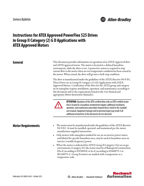
Publication 520-SB001A-EN-E - October 2012Service BulletinInstructions for ATEX Approved PowerFlex 525 Drives in Group II Category (2) G D Applications with ATEX Approved MotorsGeneralThis document provides information on operation of an ATEX Approved drive and ATEX approved motor. The motor is located in a defined hazardous environment, while the drive is not. A protective system is required to stop current flow to the motor when an over temperature condition has been sensed in the motor. When sensed, the drive will go into a fault stop condition.The drive is manufactured under the guidelines of the ATEX directive 94/9/EC. These Drives are in Group II Category (2) GD Applications with ATEX Approved Motors. Certification of the drive for the ATEX group and category on its nameplate requires installation, operation, and maintenance according to this document and to the requirements found in the User Manual and appropriate Motor Instruction Manual(s).Motor Requirements•The motor must be manufactured under the guidelines of the ATEX directive 94/9/EC. It must be installed, operated, and maintained per the motor manufacturer supplied instructions.•Only motors with nameplates marked for use on an inverter power source, and labeled for specific hazardous areas, may be used in hazardous areas on inverter (variable frequency) power.•When the motor is indicated for ATEX Group II Category 2 for use in gas environments (Category 2G) the motor must be of flameproof construction, EEx d (according to EN50018) or Ex d (according to EN60079-1 or IEC60079-1). Group II motors are marked with a temperature or atemperature code.ATTENTION: Operation of this ATEX certified drive with an ATEX certified motor that is located in a hazardous environment requires additional installation, operation, and maintenance procedures beyond those stated in the standard user manual. Equipment damage and/or personal injury may result if all additional instructions in this document are not observed.Instructions for ATEX Approved PowerFlex 525 Drives in Group II Category (2) G D Applications with ATEX Approved Motors•When the motor is indicated for ATEX Group II Category 2 for use in dustenvironments (Category 2D) the motor must be protected by an enclosure(according to EN50281-1-1 or according to IEC61241-1: Ex tD). Group IImotors are marked with a temperature.•The motor over temperature signal supplied to the drive must be a normallyclosed contact (open during over temperature condition) compatible withthe drive’s digital (logic) input circuitry. If multiple sensors are required inthe motor, the connection at the drive must be the resultant of all requiredcontacts wired in series. Note that the drives are available with 24V DCinput circuitry. Refer to the drive User Manual for details.•Refer to all product markings for additional cautions that may apply.•Typical motor markings are contained on a motor certification nameplatesimilar to Sample Motor Nameplate.Sample Motor Nameplate ArrayDrive Wiring ATEX certification of this drive requires that 2 separate digital (logic) inputs beconfigured to monitor a normally closed over temperature contact (or multiplecontacts wired in series) presented to the drive from the motor.The 2 safety input terminals (S1 and S2) must be wired in “parallel” (jumper isacceptable) so each is monitoring the over temperature contacts. Digital signalinputs are wired with respect to the digital input common. Refer to the drive UserManual regarding setup for either internal or external 24V DC logic power.Motor supplied contacts must have ratings compatible with the drive’s inputcircuit ratings and applied voltage level.Wiring ExampleExternal Power Supply Internal 24V Power Supply2Rockwell Automation Publication 520-SB001A-EN-E - October 2012Instructions for ATEX Approved PowerFlex 525 Drives in Group II Category (2) G D Applications with ATEX Approved Motors By default, deactivation of safety input S1 or S2 will shut down the drive and put it into a fault condition that will require a fault reset before the drive can be restarted.Start-Up & Periodic Drive Testing RequirementThe integrity of both S1 and S2 inputs must be maintained and verified periodically to meet certification requirements. The interval must be determined by the requirements of the application, but not be greater than one year. In addition to any requirements to check the integrity of the over temperature device(s) and the wiring of the over temperature contact closure to the drive terminals, the drive circuitry itself requires testing. This must be done during a maintenance period when the motor environment is not hazardous and all necessary precautions have been taken to repeatedly start and stop the drive and motor safely.Preparation1.Disconnect all power from the drive including control power, if supplied.2.Disconnect the motor from the driven load if necessary, to run this test.3.Disconnect the motor over temperature contact connections from the drive.This includes both terminals S1 and S2. Remove the jumper between thetwo inputs if one is in place.4.Connect a means to open and close a N.C. contact between terminals S1 andS+. Connect a separate means to open and close a N.C. contact betweenterminals S2 and S+ (see Example T est Circuit). The switching devices(pushbutton, relay, etc.) must have contacts rated for either 24V DC orhigher.ATTENTION: Power must be applied to the drive to perform the followingprocedure. Some of the voltages present are at incoming line potential. To avoidelectric shock hazard or damage to equipment, only qualified service personnelshould perform the following procedure. Thoroughly read and understand theprocedure before beginning. If an event does not occur while performing thisprocedure, Do Not Proceed. Remove Power including user supplied controlvoltages. User supplied voltages may exist even when main AC power is notapplied to then drive. Correct the malfunction before continuing.Rockwell Automation Publication 520-SB001A-EN-E - October 201234Rockwell Automation Publication 520-SB001A-EN-E - October 2012Instructions for ATEX Approved PowerFlex 525 Drives in Group II Category (2) G D Applications with ATEX Approved Motors Example Test Circuit 5.Be sure both sets of test contacts are closed. Assure all control connections are properly made to the drive. Reapply power to the drive including external control power, if supplied.Test 6.Perform any necessary parameter adjustments and start the drive. Confirm that the drive stops and starts normally, then start and slowly accelerate the motor.7.Operate the two contacts in combinations as described in the table below and verify the response of the drive. The drive should stop and the motor coast to rest when ever a contact is opened. 8.Disconnect the test switching devices from the two safety inputs.9.Determine a way to interrupt the continuity of the over temperature circuit when it is reconnected to the motor.10.Properly reconnect the motor over temperature contact connection to the drive and include the test mechanism to interrupt the over temperature circuit’s continuity. This includes both terminals S1 and S2. Reconnect the jumper between the two inputs if one had been in place.11.Reconnect power to the drive including external control power.12.Start drive and confirm that it is operating properly.Safety Function Status Drive In Safe State Drive In Safe State Drive In Safe State Drive Able to Run Drive Status Configured by t105[Safety Open EN]Fault F111[Safety Hardware]Fault F111[Safety Hardware]Ready/Run Safety Channel Operation Safety Input 1No Power Applied Power Applied No Power Applied Power Applied Safety Input 2No Power Applied No Power Applied Power Applied Power Applied IMPORTANT The drive should not start when closing a safety input even if a maintained start command is present and had not been removed whenthe drive stopped.External Power Supply Internal 24V Power SupplyInstructions for ATEX Approved PowerFlex 525 Drives in Group II Category (2) G D Applications with ATEX Approved Motors13.Interrupt the continuity of the over temperature circuit connected to thedrive. The drive should stop and the motor coast to rest. The HIM/OIMshould indicate that the drive is in an Safety Open fault condition.14.Remake continuity of the over temperature circuit connected to the drive’sdigital inputs. The drive should remain stopped and in an Safety Open fault condition.15.Provide the command to restart the drive. In the case of a maintained start,remove and reapply the start command. The drive should remain stoppedand in an Safety Open fault condition.16.Provide a fault reset command to the drive. The drive fault should clear butthe drive should not restart.17.Provide the command to restart the drive. The drive should run normally.18.Stop the drive and disconnect all power including external control power.19.Remove the test mechanism, reconnect original wires and verify all wiring.20.Reconnect the motor to the load if it had been previously disconnected.21.Check for proper operation.Rockwell Automation Publication 520-SB001A-EN-E - October 20125Instructions for ATEX Approved PowerFlex 525 Drives in Group II Category (2) G D Applications with ATEX Approved MotorsU.S.Allen-BradleyDrivesTechnicalSupport-Tel:(1)262.512.8176,Fax:(1)262.512.2222,E-mail:*****************Online: /support/abdrivesAllen-Bradley, Rockwell Software, Rockwell Automation, PowerFlex and TechConnect are trademarks of Rockwell Automation, Inc.Trademarks not belonging to Rockwell Automation are property of their respective companies.Publication 520-SB001A-EN-E - October 2012Copyright © 2012 Rockwell Automation, Inc. All rights reserved.。
APx音频测试仪操作说明书

• 共模抑制比 CMRR IEC-60628 • 直流偏移 DC LEVEL • 最大輸出功率-BURST • 聲學參數測量 SPL,THD • 數字信號誤碼分析 • HDMI 數字音頻分析(HDMI Option) • 芯片級別的數字信號分析(DSIO Option) • 藍牙音頻傳輸性能指標 • PDM脈衝密度調制碼流音頻指標 • PESQ聲音質量指數評估
• 具有过载保护功能
非平衡輸出, 主要用於消費類音頻領域
平衡方式輸出, 主要用於專業音頻領域 兩通道/四通道系列硬件
八通道系列硬件
模拟输入模块
• 2通道,4通道或8通道輸入 • 平衡、非平衡輸入接口 • 输入信号范围 0.32 V 到300 V (根據儀器型號) • 输入阻抗 100 kΩ 或者600 Ω| • 共模抑制比CMRR ≥80 dB, 5 Hz to 5 kHz • 串音
非平衡输入,主要用于消费类音頻
平衡输入,主要用于专业音响、广播领域 兩通道/四通道系列硬件
八通道系列硬件
數字輸入/輸出模塊
• 數字接口類型
Balance: AES3,EBU-3250,IEC60958-4
Unbalance: AES3-id,SPDIF, IEC60958-3
• 數字音頻格式
• Linear PCM 格式輸出 • Dolby, DTS等編碼格式輸出(加載信
APx500 Series Option
HDMI option
DSIO option
Bluetooth
AUX-0100
PDM
模擬輸出模塊
• 2通道或8通道輸出
APx515测试方法

o
APx Training
深圳爱普泰科电子有限公司
Slide 13
APx500 设计原理
• 测试工程文件
o
单一文件
• 测试参数 • 測試設置 • 测试限制文件 • 多个信号测试路径 • 用户自定义
APx Training
深圳爱普泰科电子有限公司
Slide 14
运行一系列测试
测试导航
• 对所有的测量项目提供可视化导航. • 信号路径展现唯一的I/O配置. • 当测试系列运行时,对每个测试项目的测试结果 有pass/fail显示. • 对测试项目可以做系列测试,也可以单独测试.
•
电平
o o o
•平衡输出,主要用于专业音响、广播领域
•
噪声成分
o
APx Training
深圳爱普泰科电子有限公司
Slide 5
数字输入输出模块
• 數字接口類型
Balance: AES3,EBU-3250,IEC60958-4 Unbalance: AES3-id,SPDIF, IEC60958-3
5
APx Training
深圳爱普泰科电子有限公司
Slide 24
测试步骤APx500 测试步骤-測試結果讀取
• 條形圖顯示 • 掃描曲線顯示
APx Training
深圳爱普泰科电子有限公司
Slide 25
APx500測試結果判定 APx500測試結果判定
• 点击限制编辑工具按钮 ,编辑判 定条件-Limits,让软件自动判定测试 结果Pass/Fail • 对于条状图的Limit设定 • 对于扫描曲线的Limit设定
APx Technical Presentation
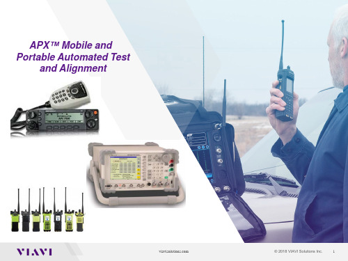
APX N50单带P25可移动两通讯设备说明书
APX N50 SINGLE-BAND P25 PORTABLE TWO-WAY RADIOStaying connected and being able to collaborate, whenever, wherever, is a prerequisite for mobile workers.Efficient teams know every moment counts to connect workers throughout your city - no matter if its day-to-day operations, a power outage, chemical spill or catastrophic storm.Our APX N50 is a slim yet rugged pick-up-and-go radio that's designed to give first responders, public-safety support and administrative staff secure communications that they can rely on in the field, to stay organized and effectively respond to whatever the day throws at them.SIMPLE. RELIABLE. SECURE.ButtonTOUGH AS NAILSThis radio is a powerful companion in the field. The APX N50 portable radio is rated IP68, supports immersion in 2 meters of water for up to 2 hours, and tested to military standards so it’s ready to operate reliably in challenging environments.OPTIMIZING SPACE AND SPEEDThe slim design doesn’t compromise usability. A variety of features accelerate radio operation to prioritize situational awareness and quick response. Large tactile controls and programmable buttons in a familiar location allow easy access to critical presets. The tough 2.4” front display presents a menu with information at a glance, and the large keypad is easy to navigate from first use, right out of the box.CONTROL WITH YOUR VOICEViQi Basic Voice Control makes changing radio settings as simple as talking, with a touch of a button and specific voice commands. Easily switch to the home channel or your favorite presets. Adjust the volume, change an audio profile, check battery, or scan multiple channels without taking your eyes off your surroundings.SLIM AND SLEEK.TOUGH AND POWERFUL.A super compact, simple layout radio to carry around all day long. Despite its size, it retains the built-in toughness of our APX portfolio with a modern industrial design and familiar control placement.ADVANCED ACCESSORIESAUDIOWired and wireless audio accessories that fit your needs and environment. Choose between remote speaker mics, surveillance kits, headsets and more. CARRYBelt clips designed for a secure hold yet easy access to the radio when worn on the waist or uniform - so your team can keep its hands free and stay focused on the task ahead.ENERGYIf the battery dies, it jeopardizes everything. We offer a selection of IMPRES 2 batteries to provide energy for a full shift and a UL DIV 1 optionfor safety in HAZLOC environments. A choice of charging solutions enables you to charge one or up to six batteries simultaneously, so your radios are always ready for the next shift. ANTENNASOur redesigned antennas are built for comfort without compromising performance. Short and flexible, these antennas conform to your mission-critical environments.HIGH DYNAMIC RANGE MICROPHONES (HDR)Two high quality mics with a high overload point pick up and reproduce voices with excellent clarity. There’s no audio clipping or distortion, even when shouting. A custom speaker delivers not only loud, but clear audio for unruly scenarios - because every syllable counts.ADAPTIVE AUDIO ENGINEBuilding upon the latest architecture is our proven APX Adaptive Audio Engine. It dynamically adjusts to give you the best audio in any environment. Sophisticated algorithms filter out unpredictable background noise and wind while working in tandem with the multiple microphones that track your voice from every angle, allowing you to speak into the radio without degrading speech quality.ENVIRONMENTALLY AWARE AUDIOAdditional environmentally aware audio features, Receive Volume Leveling and Noise Sensing Volume Control, keep your hands off the volume knob and your attention forward. Set the volume once and the APX N50 radio will automatically adjust for loud or soft talkers, and the changing ambient noise loudness in your surroundings – giving you the right volume at the right time.MESSAGES GET THROUGH LOUD AND CLEAR IN NOISY ENVIRONMENTS.SEND AUDIO WITHOUT SECOND GUESSING.MACE HARDWARE PROTECTEDProtect sensitive information from eavesdroppers. Multiple hardware encryption algorithms including 256-bit AES, DES and ADP can be loaded to a MACE hardware encryption module that stores up to 48 keys and meets FIPS 140-3 level 1, level 3 and FIPS 197 standards. Securely update encryption keys with over-the-air rekeying (OTAR).SECURE COMMUNICATIONS. EFFICIENTLY MANAGED.OPTIMIZE FLEET MANAGEMENTOptimize fleet management by programming radios online in batches over Wi-Fi or OTAP , or use to CPS for basic one-by-one offline programming. Managing a large fleet of radios can be complex, especially when your team requests changes to fielded radios. Leverage Radio Management to view your entire fleet from a single interface and efficiently push batch programming changes in minutes. Our team of experts is here to guide your transition from CPS to our advanced software programming platforms, whether you use a cable, Wi-Fi or OTAP.CONNE CT AN D COLLA BORAT E. CONNECT S EAMLESSLYWith the latest c ollaborative feat ures,the APX N50 is a radio you can re ly on to connect teams, a gencies and dep artments across boundarie s with fast, inter operable communications. Connect across multiple frequencies, mod es and protocols including Analog, Digital P25, Conventiona l or Trunked. COMMUNIC ATE RELIAB LYWith SmartConn ect, APX N50 ca n automatically sw itch between the P25 radio system and available broadb and networks, using Wi-Fi to extend v oice channel reach to help highly mob ile users retain connectio n when moving o ut of P25 coverage. The ra dio connects sea mlessly with accessories, sensors and oth er devices via Bluetooth 4.2 or Wi-Fi and fea tures GPS location tra cking to keep wo rkerssafe and improve task assignmen t.Motorola Solutions, Inc. 500 West Monroe Street, Chicago, Il 60661 U.S.A. For more information, please visit us on the web at: /APXN50。
Apx525使用说明+功能
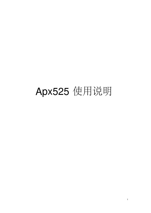
图 12 监视器
10
APx525使用说明 APx525 提供了一系列监视器去显示详细的信号输入和其他数据 的信息,并且不会修改当前测量的视图。 监视器分为七种,下面分别对其进行介绍: (1)、Scope Monitor (范围监视器): 范围监视器提供了一种显示 XY 图形的示波器视图。 (2)、FFT Spectrum Monitor( FFT 频谱监视器): FFT 频谱监视器提供了一种显示 XY 图形的频域谱视图。 (3)、Meters Monitor(米监视器): 米监视器通过以表格的形式显示每个通道的水平、 总谐波失真加 噪声、频率 (4)、Aux Control Monitor (辅助控制监视器) : 辅助控制监视器显示了当前设备的辅助控制出和入的状态位。 (5)、Metadata Monitor:Status Bits(数据监控:状态位) : 状态位的数据监控显示了在数字输入信号中通道状态位的数据 监控。 (6)、Metadata Monitor:HDMI (数据监控:高清晰度多媒体接口) : 使用高清晰度多媒体接口数据监视器前,必须安装 HDMI 操作 或者 HDMI+ARC 操作。 (7)、Bluetooth Monitor (蓝牙监视器): 蓝牙监视器显示一系列当前蓝牙连接区域的状态和当前的数据。
3
APx525使用说明 【 1】产品在开发测试阶段时,团队协作,测试资料共享是很重 要的; 【 2】、测试项目文件中包含信号连接路径, 测试项目,相关设置, 上下限和自动化测试序列等信息。
2、 APx525 说明
快速浏览: APx525 工作空间
菜单栏 工具栏 工具栏
测试向导
监视器
测量参数设置面板
9
APx525使用说明 电平、偏差进行测量。 (7)、Signal to Noise Ratio(信噪比):提供一种测量被测设备输出信 号的信噪比的方法。 ( 8)、 Crosstalk(串音):防止正在被激励的通道受激励设备通道的 影响。 (9)、Interchannel Phas(e 相位):提供一种被测设备通道间相关联的 相位的测试方法。 (10)、Add Measuremen(t 增加测量步骤):还可以对以上的测量步 骤进行增加。 除了以上的信号路径设置以外还可以通过 Add Signal Path 增加信号 路径,设置完成以上步骤以后,通过 Report 查看序列的结果,并通 过 Data Output 将数据导出。
Microsoft Word - APx525测试仪操作说明

APx525测试仪操作说明1.双击打开桌面AP测试软件;2.测试参数前的设置。
(1)点击右侧菜单Signal Path Setup,在打开的界面选择相应测试端口,如下图所示(2)选择input/output下拉菜单,选中references项,修改input refercens中的阻抗和频率选项。
如下图修改完成之后,点击Generator off 变成Generator on,检测有无信号输出与被测机型的频率一致3.测试失真THD+N Ratio与功率RMS Level参数选择右侧菜单Stepped Level Sweep项。
(1)修改测试频率如下图此处与前面步骤2.(2)参考设置的频率要一致。
(2)调整点数Points,使得Step Size的值不大于3mVms,如图所示。
(3)两通道分开扫描:首先关闭通道2,点击start扫描出通道1的曲线;然后勾选Append Graph Data,同样的方法扫描出通道2的曲线。
点击start键开始扫描曲线此状态表示关闭通道2打开通道1.勾选Append GraphData添加通道2的曲线正在扫描通道2的曲线。
(4)失真THD+N Ratio与功率RMS Level曲线如下图如图可看出输入灵敏度和输出功率:X值为输入灵敏度,Y值是功率值。
4.测试失真度THD在Signal Path Setup 中找到THD+N Ratio,点开测试界面如下图。
输入上面测试的灵敏度的值,点击Generator off 变成Generator on,如下图。
5.测试信噪比找到Signal to Noise Ratio 输入灵敏度,点击start,如下图。
这里输入灵敏度的值这里读出失真度与被测机型的频率一致6.测试通道分离度找到Crosstalk,界面如图,输入通道灵敏度,点击start读数。
若选择A-wt.测试的是计权的值。
7.测试输出噪音找到Noise(RMS),直接读数。
安桥525连接蓝牙教程(一)
安桥525连接蓝牙教程(一)安桥525连接蓝牙教程概述•本教程将详细介绍如何使用安桥525连接蓝牙设备•安桥525是一款具有蓝牙功能的设备,可以与其他蓝牙设备进行无线连接•连接蓝牙设备能够实现数据传输、音频播放等功能步骤一:准备工作1.确保你拥有一台安桥525设备和蓝牙设备2.确保蓝牙设备已开启蓝牙功能3.确保安桥525设备已开启蓝牙功能步骤二:打开安桥525的蓝牙设置1.在安桥525设备上找到并点击设置菜单2.在设置菜单中找到蓝牙设置选项并点击进入步骤三:搜索蓝牙设备1.在蓝牙设置界面中点击“搜索新设备”按钮2.安桥525将会开始搜索附近的蓝牙设备步骤四:连接蓝牙设备1.在搜索结果中找到你要连接的蓝牙设备2.点击该设备名称以开始连接3.根据蓝牙设备要求,输入配对密码或确认配对请求步骤五:完成连接1.如果一切顺利,你将会看到安桥525和蓝牙设备成功配对2.现在你可以开始使用连接的蓝牙设备了小结通过本教程,你学会了如何使用安桥525连接蓝牙设备。
连接后,你可以享受无线数据传输和音频播放等功能。
请确保在连接蓝牙设备时遵循设备要求,以保证顺利完成配对。
安桥525连接蓝牙教程(续)注意事项•在连接蓝牙设备之前,请确保设备之间的距离在有效范围内,通常为10米左右•不同的蓝牙设备可能有不同的配对要求,请根据设备提示进行操作•如果在连接过程中遇到问题,可以通过重新搜索和尝试连接解决大多数问题扩展功能•一旦安桥525成功连接蓝牙设备,你可以尝试以下扩展功能:–数据传输:通过蓝牙连接,你可以在安桥525和蓝牙设备之间传输文件、图片、音频等数据。
–音频播放:将安桥525连接到蓝牙音箱或耳机,享受无线的音乐和音频体验。
–手机控制:某些蓝牙设备允许你使用手机控制特定功能,如远程拍照、音量调节等。
常见问题解答以下是一些可能遇到的问题及解决方法: 1. 无法搜索到蓝牙设备: - 确保蓝牙设备已打开并处于可被发现模式 - 确保安桥525与蓝牙设备之间的距离在有效范围内2.连接失败或配对失败:–重启安桥525和蓝牙设备,然后重新尝试连接–确保输入正确的配对密码或按照设备要求进行配对3.连接不稳定或断开频繁:–确保安桥525和蓝牙设备之间没有障碍物干扰–尝试将设备的蓝牙固件更新到最新版本如果你遇到了其他问题,建议查阅安桥525和蓝牙设备的用户手册,或咨询设备的售后服务。
AP测试【处理器】教程1.0

测试结果
5.数据单位
频率回应、2
RMS Level 点击,滚动鼠标放大曲线
扫描范围20Hz到50KHz
频率回应、3
Gain 点击,滚动鼠标放大曲线
上浮0.16dB
下浮0.15dB
扫描范围20Hz到50KHz
★
系统群延时
系统群延时
1.声响应 2.延时
dBFS 最后我们来看看和我们联系最密切的dBFS 。dBFS的全称是"Decibels Full Scale"(全 分贝刻度)——是一种为数字音频设备创 立的分贝值表示方法。
20Hz-20KHz 1、超低频20Hz-40Hz 2、低频40Hz-80Hz 3、中低频80Hz-160Hz 4、中频160Hz-1280Hz 5、中高频1280Hz-2560Hz 6、高频2560Hz-5120Hz 7、超高频5120Hz-20000Hz
2018
【处理器】测试教程
目录
一、测试系统搭建
1、器材准备 2、设备安装接线 二、Audio Precison (音频分析仪) 1、AP硬件 2、AP软件 3、信号路径的设置 4、添加测试项目 5、工程保存 三、测试项目
1、扫描电平; 2、增益; 3、THD+N; 4、最大输入与最大输出; 6、信噪比; 7、动态范围; 8、等效噪声;
未检测到硬件,检查仪器是否已接通并通电。 选择演示模式以无硬件运行。
仪器类型
演示模式 取消
AP软件、2
保存工程
自动测试按钮
菜单栏 工具栏
模式选择 测试结果保存;曲线数据;上下限;单位选择区
测试导航栏
参数设置区
信号监视区
APX NEXT XN P25智能无线电说明书

CHAOS DOESN’T CALL AHEAD. ROUTINE CAN TURN EXTREMEWITHOUT A MOMENT’S NOTICE.The equipment you use must be as versatile and reliable as you are - taking on routine calls one minute and the most threatening situations the next. The success of the incident relies on the adaptability and resiliency of you, your equipment and your crew. The APX NEXT XN P25 Smart Radio is designed with unprecedented durability, ready to operate in day-to-day situations to the most extreme environments. It mobilizes intelligence to bring vital information to your hands forimproved collaboration with your crew — so you can outperform whatever the unexpected throws at you.OUTPERFORM WHATEVER THEUNEXPECTED THROWS AT YOU WITH APX NEXT XNMISSION-CRITICAL RADIOOPERATE INUNCHARTED EXTREMES.YOU HAVE SEEN TOUGH, BUT NOT LIKE THIS.APX NEXT XN TAKES TOUGHNESS TO A NEW LEVEL, WITH NFPA 1802 CERTIFICATION FOR USE IN THE HAZARD ZONE. FROZEN, HEATED, DROWNED, FLASH FRIED, DROPPED AND TUMBLED.THIS RADIO IS READY FOR UNEXPECTED EXTREMES.ADDED SOFTWARE FEATURES ENHANCE FIREGROUND SAFETY.• Withstands 500ºF (260ºC) conditions for 5 minutes• Withstands 350ºF (177ºF) conditions for 15 minutes then immersed into 4.9 ft (1.5 m) of water • T hree radios exposed to 72ºF (22ºC), -4ºF (-20ºC), 160ºF (71ºC) are dropped eight times from 9.8 ft (3 m)• Resists direct flames for 10 secondsRadio self-checks are performed on initial power up and periodic self-checks every five minutes for:• Battery level • Radio temperature• Antenna and RSM connectionsAudible and Visual Alerts during:• Connection failures • Battery levels • Emergency button press • Self-check failures • Over temperature • Power cycle• Connecting new accessory • Out-of-range• Loss of a connection to a systemNotable NFPA 1802 test requirementsTHE 2,000 MOST RECENT ACTIONS ARE LOGGED IN THE RADIO AND DOWNLOADABLE FOR POST-INCIDENT REVIEW.SHOWCASING LEADING APX AUDIO.RUGGEDNESS AND SAFETY IS BOLSTERED WITH ADVANCED AUDIO TECHNIQUES IN BOTH THE APX NEXT XN RADIO AND XVN500 RSM SO YOUR LIFELINE WILL ADAPT ITS AUDIO OUTPUT WHEN CALM TURNS TO CHAOS FOR THE MOST INTELLIGIBLE AUDIO IN ANY ENVIRONMENT.HIGH DYNAMIC RANGE (HDR) MICROPHONESAPX NEXT XN features two HDR microphones, which improve intelligibility with extremely loud and soft inputs, and reduce noise and distortion across the range. The XVN500 RSM goes even further, with four HDR microphones and a larger loudspeaker that increases the clarity of the audio while maintaining superior loudness output. Even in stressful situations that lead to shouting, your firefighters will transmit more intelligible speech. ADAPTIVE AUDIO ENGINEOur proven adaptive audio engine works in tandem with the multiple HDR microphones to reduce the effects of unpredictable background noise in loud or windy environments. The microphones feed into sophisticated algorithms which track your voice and filter out the surrounding noise for superior intelligibility. And arranged for all-round coverage, multiple microphones ensure your voice is heard from every direction and different usage positions – even while using an SCBA mask.RECEIVE VOLUME LEVELINGSet the radio volume once.Automatic Receive Volume Levelingensures radio communicationsare heard at similar loudness, sothere’s no need to constantly adjustthe volume between loud and softtalkers throughout your shift.WHEN YOU NEED TO LEVERAGEYOUR LIFELINE TO GO BEYONDVOICE, YOU ARE ULTRACONNECTED WITH:•L MR SINGLE OR MULTI-BANDCONFIGURATIONS• LTE• GPS• WI-FI• BLUETOOTHNATURAL USER INTERFACEFROM ADVANCED PHYSICAL ERGONOMICS, TO STREAMLINED TOUCHSCREEN INTERACTIONS, TO NEW NATURAL INTERFACES, APX NEXT XN IS DESIGNED FOR EFFORTLESS USABILITY AND VERSATILITY FOR DAY-TO-DAY OPERATIONS AND WHEN EVERYTHING IS ON THE LINE.EFFORTLESS USABILITY AND VERSATILITY.FAMILIAR ERGONOMICS AND LAYOUT.Classic oversized, intuitive knobs and buttons are easy to grip, distinguishable by touch and designed to minimize accidental activations. From display size to button positioning, the radio controls are easy to access and operate with or without gloves for all mission-critical and essential radio operations. Our familiar ergonomics are carried over from previous APX designs and now required by the latest fire service standards.RUGGEDIZED TOUCHSCREEN.This mission-critical touchscreen is designed for all-weather use. A rigid stainless steel plate supports the ulta-rugged toughened glass from underneath. A heavy-duty digitizer recognizes touches even through gloves, while rejecting false touches from the elements. With a transflective display, you are set for indoor and outdoor readability. A shallow touchscreen menu depth of three on core radio functions, speeds up navigation to quickly give you the information you need and return your focus back to your tasks.ViQi VOICE CONTROL.ViQi Voice Control reduces the time to perform simple radio functions with the touch of a button. It can be used to enable radio operation in low or high noise environments – helping maintain eyes-up awareness. The ViQi button allows for quick access to voice controls – enabling firefighters to perform actions such as changing zones, channels, check battery status, and adjusting volume without breaking focus.FROM DISPLAY SIZE TO BUTTON POSITIONING, THE RADIO CONTROLS ARE EASY TO ACCESS AND OPERATE WITH OR WITHOUT GLOVES FOR ALL MISSION-CRITICAL AND ESSENTIAL RADIO OPERATIONS .MOBILE ACCESS TO INTELLIGENCEEXPANDABLEINTELLIGENCEFOR TODAYANDBEYOND.THE NATURE OF THEINCIDENTS YOU CALL ONCAN CHANGE RAPIDLY, JUSTLIKE YOUR NEEDS FOR NEWTECHNOLOGY. APX NEXTXN OFFERS A SECURE ANDSCALABLE PLATFORM FORNEW CAPABILITIES TO BESEAMLESSLY ADDED AS YOURNEEDS EVOLVE.SMART CONNECTWhen you move beyond the limits of your radio system’s coverage, you shouldn’t have to leave your lifeline behind. Whether the demands of a call take you in the depths of an urban canyon, or providing mutual aid in the neighboring county, SmartConnect ensures your lifeline is always in reach. Automatic switching between P25 and broadband LTE maintains voice communications regardless of radio coverage. SmartConnect P25 packet routing preserves your authentication, status, talkgroups and encryption without interruptions or resets.SMART MAPPINGWhen a call quickly unfolds, keeping track of the big picture can give you the edge you need to be more effective in incident organization or firefighter safety. Get precise location information on a modern map interface - right on your radio for enhanced situational awareness in the field. See your location, findan address, drop waypoints, and stayin touch with the situation. View the location of other units and firefighters at a glance. Quickly pinpoint colleagues in distress. Simply tap to communicate. ViQi VIRTUAL PARTNERA secure cloud service allows you to use voice commands to run database queries for quick access to information – for fast, secure and eyes-up intelligence.As ViQi grows, the cloud architecture allows for new capabilities to be deployed quickly and easily without updates to radio software.SMART LOCATECutting-edge location routing servicessends your radio location data overbroadband LTE for faster updates andincreased efficiency, while expandingthe number of devices that can betracked simultaneously. SmartLocate automatically triangulatesradio location using nearby cell towersand Wi-Fi access points for greateraccuracy when indoors, deep urbancanyons, or forested areas. SMART MESSAGINGTurn your radio into a multimedia toolkit.Securely share texts, images, videos andvoicenotes across your extended team -either with individuals or groups on otherradios or smartphones. Need informationabout an incident? Send a text. Have acitizen who is able to send in pictureswhile reporting an incident? Dispatch canshare with others responding to the callfor better preparation. SmartMessaging is designed specificallyfor public safety, built right into theAPX NEXT XN homescreen for quick,intuitive use, while keeping contentsecurely stored for future reference. PUBLIC SAFETY APPLICATIONS PLATFORM The APX NEXT XN application foundationis designed for extensibility, withfeedback from you. Motorola Solutionsis continually exploring ways to enabledata augmentation from across thepublic safety landscape – including radio,broadband, video, public and privatedata sources – to improve the everydayworkflow and safety of firefighters.PROVISION AND OPTIMIZE FLEET MANAGEMENT.APX NEXT XN GIVES YOU BACK TIME WITH ITS STREAMLINED OWNERSHIP EXPERIENCE – SO YOUR VALUABLE RESOURCES STAY FOCUSED AND READY. STREAMLINED OWNERSHIP EXPERIENCEEFFICIENT BATCH PROGRAMMINGManaging a large fleet of radios canbe complex, especially when your team requests changes to fielded radios. Leverage RadioCentral or Radio Management to view your entire fleet from a single interface and efficiently push batch programming changes in minutes. Our team of experts is hereto guide your transition from CPS to our advanced software programming platforms, whether you use a cable, Wi-Fi or LTE SmartProgramming. We also offer an array of support services to ensure your fleet can be conveniently managed to optimize your communications.SMART PROGRAMMING SmartProgramming coupled with RadioCentral allows initial programming, software, security updates and radio data collection to be sent over LTE. Updates and radio data can be sent at anytime, anywhere utilizing the higher speed bandwidth and extended coverage of the LTE network.XVN500 RSM IMPRES 2 Standard Capacity Battery, Div 2APX NEXT XNLeather Carry Case Whip All-Band AntennaRELY ON US TO HELP YOU ACHIEVE YOUR PERFORMANCE TARGETS WITH THE RIGHT SERVICE LEVEL YOU NEED FOR SYSTEMS, DEVICES AND APPLICATIONS. MANAGED AND SUPPORT SERVICES MYVIEW A web-based platform that gives you a transparent,single source view of fleet status and service deliveryinformation to help make smarter, faster and moreproactive decisions.TECHNICAL SUPPORT Industry certified technical engineers can troubleshoot and provide prompt resolution to any technical issues, whether on-site dispatch or remote.HARDWARE REPAIR AND SOFTWARE MAINTENANCE Ensure continuous security, performance and enhancedfunctionality of your two-way radios by getting accessto APX NEXT XN certified and tested release softwareupdates and upgrades and protect your radios fromnormal wear and tear.ACCIDENTAL DAMAGERadios are protected from accidental breakage orliquid spills and physical damage. With state-of-the-art diagnostic equipment all of your agency’s radiocomponents are protected in the event of an unexpectedfailure and are back in operation as soon as possible.Each package provides a higher level of support, transferring the risk and responsibility to Motorola Solutions. We provide a range of service capabilities, including:DEVICE PROGRAMMINGAPX NEXT XN includes Customer Programming Software (CPS) for one-at-a-time programming. We can enable batch programming for radios with centralized management to dramatically reduce the time and resources needed to provision and update your radio fleet.As an add-on service, our technical teams canhelp you provision and program your fleet ofradios on-site and train your staff on the radiofleet commissioning and management.PREVENTIVE MAINTENANCEOur certified technicians conduct annual maintenance checks to help extend the useful life of your radios, reducing repair and replacement costs.。
APX 500 音频分析仪 使用简易图解
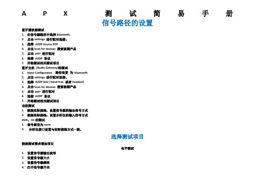
A P X测试简易手册信号路径的设置蓝牙播放器测试1.在信号源路径中选择bluetooth.2.点击settings 进行配对连接。
3.选择A2DP Source HSP4.点击Scan for devices 搜索被测产品5.点击pair 进行配对6.连接A2DP 协议7.开始测试相关测试项目蓝牙主机(Audio Gateway)的测试1.Input Configuraton 路径设置为bluetooth2.点击settings 进行配对连接。
3.选择A2DP link ( Hand-free 或者headset)4.点击Scan for devices 搜索被测产品5.点击pair 进行配对6.连接A2DP 协议7.开始测试相关测试项目功放测试1.根据实际接线,设置信号源的输出信号方式2.根据实际接线,设置分析仪的输入信号方式DVD、CD的测试1.信号源设为none2.分析仪接口设置与实际接线方式一致。
选择测试项目根据测试需求增加项目电平测试1.设置信号源输出波形2.设置信号源大小3.设置信号源频率4.打开信号源开关5.读取测量值失真测试1设置信号源输出波形,2设置信号源大小3设置信号源频率4打开信号源开关5按需求设置滤波器6读取测量值信噪比测试1设置信号源输出波形2设置信号源大小3设置信号源频率4打开信号源开关5按需求设置滤波器6读取测量值频率扫描测试1.设置信号源波形2.设置信号源大小3.设置信号源开始频率,结束频率,扫描点数4.设置滤波器5.点击Start 开始测试。
总谐波失真加噪声频率扫描测试1设置信号源波形2设置信号源大小3设置信号源开始频率,结束频率,扫描点数4设置滤波器5 点击Start 开始测试生成测试报告。
摩托拉拉 APX 车载适配器说明书
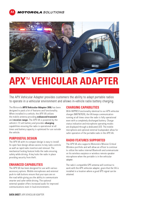
T he APX Vehicular Adapter provides customers the ability to adapt portable radios to operate in a vehicular environment and allows in-vehicle radio battery charging.The Motorola APX Vehicular Adapter (VA) has been designed to pack a lot of features and functionality. When installed in a vehicle, the APX VA utilizes the mobile antenna providing enhanced transmit and receive range. The APX VA is powered by the vehicle’s 12 volt battery and provides charging capabilities ensuring the radio is operational at all times and battery capacity is optimized for use outside the vehicle.PURPOSEFUL DESIGNThe APX VA with its compact design is easy to install. Its open face design allows access to key radio controls as well as rapid radio insertion and removal. The mechanical locking feature holds the radio ensuring safety while driving. A key locks the radio in place providing security from theft.ENHANCED CAPABILITIESThe APX VA has been designed for use with various accessory options. Mobile microphones and external push-to-talk buttons ensure that your eyes are on the road while giving you the ability to communicate smarter and safer while driving. The optionalexternal speaker offers increased audio for improved communications even in loud environments.APX ™VEHICULAR ADAPTERCHARGING CAPABILITIESWith IMPRES functionality identical to our APX vehicular charger (NNTN7624), the VA keeps communication running at all times since the radio is fully operational even with a completely discharged battery. Charge status indication and microphone operating modes are displayed through a dedicated LED. The mobile microphone and optional external loudspeaker allow for safer operation of the portable radio in the APX VA.RADIO FEATURES SUPPORTEDThe APX VA also supports Motorola’s Mission Critical Wireless portfolio and will allow an officer to continue to utilize the radios internal Bluetooth and communicate on his wireless earpiece or wireless remote speaker microphone when the portable is in the vehicular adapter.The radio’s compatible GPS antenna will continue to work with the APX vehicular adapter, given that the VA is installed in a location where a good GPS signal can beattained.Radio Compatibility APX 8000, APX 8000XE, APX 6000, APX 6000Li, APX 6000XE, and SRX 2200Battery Compatibility NNTN7038, NNTN8092, PMNN4403, NNTN8182, PMNN4547,PMNN4485, PMNN4486, PMNN4504, NNTN8930, PMNN4547Supply VoltageNominal 13.8 VoltsTemperatureCharging +10°C to +40°COperating -30°C to +60°CStorage -55°C to +85°CDimensions(L x W x H) in 10 x 5.4 x 3.3Specification*VHF UHF (Band 1/Band 2)7/800 MHzFrequency Range (MHz) 136-174380-470/450-520RX: 764-776 / 851-870TX: 764-776, 794-806 / 806-825, 851-870 Power (Watts)6530.283µVAnalog Sensitivity (12dB SINAD)0.17µV0.229/0.215µV*Based on APX 6000 Radio Specification.Vehicle Current Discharged Battery Charged BatteryVehicle OFF (mAdc)2 2 (If radio is out of the VA; 10mA if in) Vehicle ON/Radio ONRadio Standby (mAdc)1000220Radio Rx (mAdc)1000220Radio Rx w/External Speaker (mAdc)20001000Radio Tx (mAdc)1000220Audio OutputBasic 500 mW (with less than 5% distortion)Optional External Speaker 7.5W (with less than 10% distortion)For optimum receiver sensitivity it is recommended that a 3 dB gain antenna with low-loss co-ax be ordered with 800 MHz systems.APX VEHICULAR ADAPTER ORDERING GUIDELow Temperature Operational MIL-STD-810G, Method 502.5, Procedure II High Temperature Operational MIL-STD-810G, Method 501.5, Procedure IILow Temperature Storage MIL-STD-810G, Method 502.5, Procedure I, Category 3 (Severe Cold) High Temperature Storage MIL-STD-810G, Method 501.5, Procedure I-A1 Thermal Shock MIL-STD-810G, Method 503.5, Procedure I - CHigh Humidity Endurance MIL-STD-810G, Method 507.5, Procedure II (507.5-7 Aggravated Temperature Cycle)Shock Functional MIL-STD-810G, Method 516.6, Procedure I Shock Crash Hazard MIL-STD-810G, Method 516.6, Procedure V Shock Bench Handling MIL-STD-810G, Method 516.6, Procedure VI Life Cycle100,000 cyclesFused power cable 2 keys for the lockScrews for attaching VA to the trunnion Safety leaflet / quick start guideHAD4006¼-wave (136 – 144)HAD4007¼-wave (144 – 150.8)HAD4008¼-wave (150.8 – 162)HAD4009¼-wave (162 – 174)HAD4021Wideband (136 – 174)HAD4022 3 dB gain (136 – 174)HAE4003¼-wave (450 – 470)HAE4004¼-wave (470 – 512)HAE4011 3.5 dB gain (450 – 470)HAE4013 3.5 dB gain (494 – 512)HAE6010 3.5 dB gain (380 – 433)HAE6011 5 dB gain (380 – 433)HAE6012¼-wave (380 – 433)HAE6013 3 dB gain, Stubby (762 – 870)HAF4013 3 dB gain, Stubby (762 – 870)HAF4014 3 dB gain, Elevated Feed (762 – 870)HAF4016¼-wave (762 – 870)HAF40173 dB gain, Co – Linear (762 – 870)AUDIO ACCESSORIESCONNECTION OF THE BELOW AUDIO ACCESSORIES WILL REQUIRE THE HLN6961 MOBILE ACCESSORY PORT CONNECTOR AND 3980034F04 PINS.HMN1090Handheld Palm MicrophoneHMN4079Keypad MicrophoneRMN5054 IMPRES Visor MicrophoneHSN4038 External Speaker, 7.5WattHLN5391 Microphone Hang-Up ClipPMKN4093 Microphone Extension Cable, 2-feetfor HMN1090EXTERNAL CONTROLSHLN5131Emergency Push ButtonHLN5113 Emergency FootswitchGLN7278External Push-to-Talk Foot SwitchRLN5926 External Push Button Push-to-Talk Switch WIRELESS AUDIO ACCESSORIESNTN2570Mission Critical Wireless Earpiece with 12.5" cableRLN6544APX Wireless RSM w/ Battery, ClipRLN6554APX Wireless RSM w/Battery , Clip, DUC, Power SupplyFor complete portfolio of wireless accessories click here. APX VEHICULAR ADAPTER ORDERING GUIDE*Specifications subject to change without notice.RMN5054 HMN4079 HLN5131 HLN5113 RLN6544MOTOROLA, MOTO, MOTOROLA SOLUTIONS and the Stylized M Logo are trademarks or registered trademarks of Motorola Trademark Holdings, LLC and are used under license. All other trademarks are the property of their respective owners. ©2016 Motorola Solutions, Inc. All rights reserved. 02-2018。
APX500音频分析仪使用简易图解
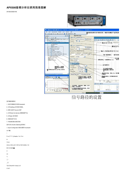
Leva TTO+S f Bi ts 289.2 uiVnus 290. 7 L /121S 回HiTf( 痢斗Qject ” AP K SDO ¥2.9 Filt Vis# 宦匕匕勺卫 aniEiitb Ti uj e21 T OQI I S 世Htlp W S 国皿IS 面匝匝IB 信号路径设置 ■j" ”圍住frpj ?et :| ■/归鹉事al 曲till D u.'Lp a.t £ OXldEl. gJLT ■&!. JL Conr s act&r ; .信号源接口设置,CD 类设为畑氏 蛊郵輻嶠实际接线q CGM.ector : Cbarjiels B^zidwidt A : BH I 廿口田 ■i - :Add …窃Ad&珀环 「画鞠坯*rt 3f Dat^. CutpuL V UIUL tor 1 '<■■■□? Si? 7KI-+H Irequenzy Respo: £i to Hoi£? Crcsslalk, One Q L ^CI T L -1 Uiidi^i v 2ntercharo.el thase Maasurement... Confirms at i?i An al o g I'nlialaiiEe T | : E Ik, JF_ 9D kMi D eviqe Usidea- T est. S e t i i F-gs Dd?y : O-dlO s Vfiri fy E i OTI 吕 Set tilths -. L&t eli.」 3wi. Se.1 .. FFT Spcctrwi H QU t?r Refer to the Melp fils infcrrnat.on al>uu.l curnpu.libit : 孕辺 ■dun -亡也二. for 测试前须先根据黨际 情况设置测试路径参 数 Output ; 选择测试项目 根据测试需求增加项目 i *19 :Z
Apx525使用说明+功能
Apx525使用说明目录1、APx525简介 (1)1.1 APx525简介 (1)1.2 APx525功能 (2)1.3 APx525优点 (2)2、APx525说明 (4)2.1 菜单栏 (5)2.2 工具栏 (7)2.3 测试向导 (8)2.4 监视器 (10)2.5 状态栏 (11)2.6 测量参数设置面板 (12)2.7 条形图面板 (16)2.8结果设置栏 (17)2.9 选择器 (18)1、APx525简介1.1 APx525简介APx525是2通道实时输入,输出快速音频分析仪,操作非常方便,简单。
不需要掌握很多的音频测量和编程经验,就能进行测试和编程操作。
大量测试项目模板已固化在电脑上,只需要选择你所需要的测试项目和要求,就可以产生自动化测试程序,自动产生各种格式的综合报告,包括图形,数字,也可以添加产品标记和公司名称。
APx是高速、高性能和友善用户而设计的。
创新发明包括“一按”测试,自动检测执行器,连续扫频技术等等,令测试17项数据只需约7秒。
APx525带2个平衡和2个不平衡输入和输出,在加上192K采样数字接口,有AES/EBU,TOSLINK光纤和SPDIF格式。
APx提供快,一按测试,结果可一页显示,数据,图形都带上下限自动检查。
通过智能对话选择,可非常快速和简单地选择滤波器和高级设定。
对于重复测试不同的输入和输出途径,可完全自动化执行,也可实时监查电平,波形和FFT频谱分析。
其他特别波形,例如方波和粉红噪声等等,可通过Apx的外置源模式播波,以测试CD、DVD和MP3播放机。
在大功率功放测试时,自动测量连续最大输出和峰值,可检视功率图谱和调控扫频,和其他符合CEA-2006和CEA-490A国际标准的测试。
APx突破性地产生信号低至0.1Hz,最大输入电压至300Vrms有效值(160V不平衡输入)和典型失真THD+N<-108(在1KHz,2.5V),没有其他同档次的产品有此高表现。
VIAVI Solutions APX 手持自动测试与对齐系统用户手册说明书
© 2018 VIAVI Solutions Inc.
7
APX Primary Test Screen
Function Keys
• F1 – Test • Start testing the radio. No alignments will be made. Only a test report of pass/fail results. Radio model will be automatically identified and appropriate specification table will be used for testing.
Motorola RLN 4510 Battery Eliminator 7.5 VDC Regulator
UNIVERSAL BATTERY
ELIMINATOR 66009254001
SMA-BNC 5880384G68
Aeroflex 3920B Service Monitor
• Go to the Cobham / Aeroflex website:
Click Here
• Click on the “Software” Tab and scroll to the section called “Software”.
• If your system version is older than the version listed on this site, then download the software, release notes and installation instructions and update your system software.
Apx525使用说明+功能

Apx525使用说明目录1、APx525简介 (1)1.1 APx525简介 (1)1.2 APx525功能 (2)1.3 APx525优点 (2)2、APx525说明 (4)2.1 菜单栏 (5)2.2 工具栏 (7)2.3 测试向导 (8)2.4 监视器 (10)2.5 状态栏 (11)2.6 测量参数设置面板 (12)2.7 条形图面板 (16)2.8结果设置栏 (17)2.9 选择器 (18)1、APx525简介1.1 APx525简介APx525是2通道实时输入,输出快速音频分析仪,操作非常方便,简单。
不需要掌握很多的音频测量和编程经验,就能进行测试和编程操作。
大量测试项目模板已固化在电脑上,只需要选择你所需要的测试项目和要求,就可以产生自动化测试程序,自动产生各种格式的综合报告,包括图形,数字,也可以添加产品标记和公司名称。
APx是高速、高性能和友善用户而设计的。
创新发明包括“一按”测试,自动检测执行器,连续扫频技术等等,令测试17项数据只需约7秒。
APx525带2个平衡和2个不平衡输入和输出,在加上192K采样数字接口,有AES/EBU,TOSLINK光纤和SPDIF格式。
APx提供快,一按测试,结果可一页显示,数据,图形都带上下限自动检查。
通过智能对话选择,可非常快速和简单地选择滤波器和高级设定。
对于重复测试不同的输入和输出途径,可完全自动化执行,也可实时监查电平,波形和FFT频谱分析。
其他特别波形,例如方波和粉红噪声等等,可通过Apx的外置源模式播波,以测试CD、DVD和MP3播放机。
在大功率功放测试时,自动测量连续最大输出和峰值,可检视功率图谱和调控扫频,和其他符合CEA-2006和CEA-490A国际标准的测试。
APx突破性地产生信号低至0.1Hz,最大输入电压至300Vrms有效值(160V不平衡输入)和典型失真THD+N<-108(在1KHz,2.5V),没有其他同档次的产品有此高表现。
APx-525,APx-515,APx-555音频分析仪音频测试仪操作说明书

3.在图示区域点击 设置上下限
APx Training
深圳市愛普泰科電子有限公司
Slide 24
APx500測試扫描曲线上下限设置
• 对于扫描曲线的限制条件设定 • 拖动鼠标绘制Limit • 编辑扫描数据,整体上、下移动曲线生成Limits
APx Training
深圳市愛普泰科電子有限公司
深圳市愛普泰科電子有限公司
Slide 20
測試步驟三之測試結果讀取
• 條形圖顯示 • 掃描曲線顯示 • 可以對測試結果選 擇不同的讀數單位
數據單位
APx Training
深圳市愛普泰科電子有限公司
Slide 21
測試結果選擇器
• 一次測量可以得到不同的結果
• 選擇所需要顯示的結果
從多個結果視圖中選擇需要的結果
Status Bit信息
數字信號元數據的狀態位
Aux控制口 特点:
o o
独立地实时显示 可变尺寸
APx Training
深圳市愛普泰科電子有限公司
Slide 23
APx500条状图上下限设置
点击限制编辑工具按钮 ,编 辑判定条件-Limits,让软件自动判定 测试结果Pass/Fail 对于条状图的上下限设置设定: ->Draw Limits->Upper/Lower,然后 在条状图上点击设置你所需要的上/ 下限;当设置好上限切换到下限时,上 限设置结果锁定不能修改,如需修改, 需点击Upper再进行设置,下限也用同 样方法 也可以进行输入编辑上下限: ->Edit Limits,如右输入设置所需 要的上下限
深圳市愛普泰科電子有限公司
Slide 9
Apx525使用说明+功能资料
Apx525使用说明目录1、APx525简介 (1)1.1 APx525简介 (1)1.2 APx525功能 (2)1.3 APx525优点 (2)2、APx525说明 (4)2.1 菜单栏 (5)2.2 工具栏 (7)2.3 测试向导 (8)2.4 监视器 (10)2.5 状态栏 (11)2.6 测量参数设置面板 (12)2.7 条形图面板 (16)2.8结果设置栏 (17)2.9 选择器 (18)1、APx525简介1.1 APx525简介APx525是2通道实时输入,输出快速音频分析仪,操作非常方便,简单。
不需要掌握很多的音频测量和编程经验,就能进行测试和编程操作。
大量测试项目模板已固化在电脑上,只需要选择你所需要的测试项目和要求,就可以产生自动化测试程序,自动产生各种格式的综合报告,包括图形,数字,也可以添加产品标记和公司名称。
APx是高速、高性能和友善用户而设计的。
创新发明包括“一按”测试,自动检测执行器,连续扫频技术等等,令测试17项数据只需约7秒。
APx525带2个平衡和2个不平衡输入和输出,在加上192K采样数字接口,有AES/EBU,TOSLINK光纤和SPDIF格式。
APx提供快,一按测试,结果可一页显示,数据,图形都带上下限自动检查。
通过智能对话选择,可非常快速和简单地选择滤波器和高级设定。
对于重复测试不同的输入和输出途径,可完全自动化执行,也可实时监查电平,波形和FFT频谱分析。
其他特别波形,例如方波和粉红噪声等等,可通过Apx的外置源模式播波,以测试CD、DVD和MP3播放机。
在大功率功放测试时,自动测量连续最大输出和峰值,可检视功率图谱和调控扫频,和其他符合CEA-2006和CEA-490A国际标准的测试。
APx突破性地产生信号低至0.1Hz,最大输入电压至300Vrms有效值(160V不平衡输入)和典型失真THD+N<-108(在1KHz,2.5V),没有其他同档次的产品有此高表现。
APx515 2通道音频分析仪-APx515 2通道音频分析仪
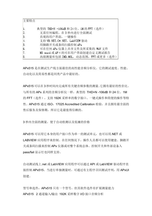
APx515是在测试生产线方面最佳的高性能音频分析仪。
它的测试速度、性能、自动化以及简易性都是同类产品中最好的。
APx515可以在3秒时间内完成所有关键音频参数的测量。
它拥有最好的性价比。
与所有的APx系列的音频分析仪一样,典型的THD+N -106dB和24位、1M的FFT(选件),支持192K采样率的数字接口、一键式操作和简便的操作等特性。
APx515通过ISO:17025 Accredited Calibration检验,并且拥有最全面的售后服务及保修期,所以它是最值得信赖的。
3秒内全面的测量,便于自动检测以及低廉的价格APx515可以用它本身的用户接口作为单一的测试单元,也可以用.NET或LABVIEW应用程序来控制。
在任何情况下,操作人员都可以使用键盘、脚踏开关或条码扫描来控制APx仪器或对整个系统总体。
控制开关和外部设备入pass/fail显示灯也同样支持。
自动测试线上.net或LabVIEW应用程序可以通过API或LabVIEW驱动程序直接控制APx515。
当进行单独测量时,可通过有主程序召回测试序列,用APxUI 创建。
型号和选件:APx515只有一个型号,但其软件选件有扩展测量能力APx515 2通道输入/输出192K采样数字I/O接口音频分析SW-HST 增加高速的多音频以及连续扫描测量SW-AML 增加IMD、MOL、动态范围、FFT以及其他高级测量工具库SW-ACR 增加声学响应测量厂商、设计商、制造商所信赖的世界上成千上万的工程人员都信赖由AP分析仪测量的结果。
合作都需要从一个互相认同的起点开始,那就是每一方的测试设备都是精确、可靠的。
事实上,多样的APx音频分析仪都使用相同的软件进行测量,这样可以便于厂商、开发人员及生产企业之间测量结果共享。
例如:使用APx525的测量工程师可以创建生产测试序列工程文件,通过邮件寄给使用APx515的代工生产商,在生产线运行该工程文件。
- 1、下载文档前请自行甄别文档内容的完整性,平台不提供额外的编辑、内容补充、找答案等附加服务。
- 2、"仅部分预览"的文档,不可在线预览部分如存在完整性等问题,可反馈申请退款(可完整预览的文档不适用该条件!)。
- 3、如文档侵犯您的权益,请联系客服反馈,我们会尽快为您处理(人工客服工作时间:9:00-18:30)。
Apx525使用说明目录1、APx525简介 (1)1.1 APx525简介 (1)1.2 APx525功能 (2)1.3 APx525优点 (2)2、APx525说明 (4)2.1 菜单栏 (5)2.2 工具栏 (7)2.3 测试向导 (8)2.4 监视器 (10)2.5 状态栏 (11)2.6 测量参数设置面板 (12)2.7 条形图面板 (16)2.8结果设置栏 (17)2.9 选择器 (18)1、APx525简介1.1 APx525简介APx525是2通道实时输入,输出快速音频分析仪,操作非常方便,简单。
不需要掌握很多的音频测量和编程经验,就能进行测试和编程操作。
大量测试项目模板已固化在电脑上,只需要选择你所需要的测试项目和要求,就可以产生自动化测试程序,自动产生各种格式的综合报告,包括图形,数字,也可以添加产品标记和公司名称。
APx是高速、高性能和友善用户而设计的。
创新发明包括“一按”测试,自动检测执行器,连续扫频技术等等,令测试17项数据只需约7秒。
APx525带2个平衡和2个不平衡输入和输出,在加上192K采样数字接口,有AES/EBU,TOSLINK光纤和SPDIF格式。
APx提供快,一按测试,结果可一页显示,数据,图形都带上下限自动检查。
通过智能对话选择,可非常快速和简单地选择滤波器和高级设定。
对于重复测试不同的输入和输出途径,可完全自动化执行,也可实时监查电平,波形和FFT频谱分析。
其他特别波形,例如方波和粉红噪声等等,可通过Apx的外置源模式播波,以测试CD、DVD和MP3播放机。
在大功率功放测试时,自动测量连续最大输出和峰值,可检视功率图谱和调控扫频,和其他符合CEA-2006和CEA-490A国际标准的测试。
APx突破性地产生信号低至0.1Hz,最大输入电压至300Vrms有效值(160V不平衡输入)和典型失真THD+N<-108(在1KHz,2.5V),没有其他同档次的产品有此高表现。
除了传统的平衡共模抑制测试,APx525是唯一一台可进行IEC 60268 SECT10N 14.15.1共模抑制比测试。
1.2 APx525功能APx525作为一个2通道音频分析仪,还具备以下功能:(1)、模拟通道数:2个输出通道和2个输入通道;(2)、数字通道:2个输出通道和2个输入通道;(3)、标准USB-2.0接口;(4)、APx软件控制;(5)、自动化测试;(6)、综合报告系统;(7)、保存和重载测试项目;(8)、2个通道实时信号监控;(9)、Continuous Sweep连续扫描。
1.3 APx525优点(1)、无需测量经验,操作非常简单【1】、以图形的方式提示正确的测试连接方法;【2】、选择不同的信号连接路径,模拟和数字不同的连接组合;【3】、2个信号源输出和2个通道输入的分析仪,平衡与非平衡方式;【4】、软件提供非常方便的操作导航器,只需要选择相应的测量项目,设置相关的频率范围与信号幅度即可进行测量。
(2)、无需编程,实现自动化编程【1】、只选择相应的测量项目,点击执行键就可进行有次序的自动化测试,可轻松改变设置或重复进行测试;【2】、根据被测产品的性能指标设置上下限,下限来判断产品是否合格;【3】、直接在被测产品的显示曲线上绘出上下限,或直接绘出上下限曲线,或在测量的数据上生成上下限;【4】、执行自动化测试程序中,测试如果超出上限或下限,测试序列会显示有标记的提示。
(3)、丰富的测试结果【1】、测试完成,自动生成测试报告;【2】、包括测试项设置,测试曲线,图形与数据,如果测试有上下限,会显示每个通道的测试结果是否通过等信息;【3】、报告格式,HTML/EXCEL等,可在报告中加插公司名称或产品标记。
(4)、共享测试项目【1】产品在开发测试阶段时,团队协作,测试资料共享是很重要的;【2】、测试项目文件中包含信号连接路径,测试项目,相关设置,上下限和自动化测试序列等信息。
2、APx525说明快速浏览:APx525工作空间 工具栏菜单栏工具栏测试向导监视器状态栏测量参数设置面板条形图面板结果设置栏选择器图1 APx525工作空间APx525工作空间包括9个主要区域;菜单栏、工具栏、测试向导、监视器、状态栏、测量参数设置面板、条形图面板、结果设置栏、选择器。
2.1 菜单栏图2 菜单栏File Menu(文件栏):包括新建工程、打开已有工程、加密工程、解密工程、保存工程、另存为、另存为工程为模板、管理工程模板、管理附加工程项目、导入条形图数据、导出条形图数据、最进浏览项目、退出。
图3 文件View menu(视图):包括范围监视器、FFT频谱监视器、公尺监视器、数据变化监视器、蓝牙监视器、监视器开关、声音信号监视器、隐藏测量向导、全屏。
图4 视图Measurements menu(测量):控制发生器开关以及当前测量参数的向导设置。
图5 测量Project(工程):包括添加删除信号通道、添加删除测量、开始测试序列、分别开始测试信号通道、测量、选择的测量序列、工程或序列属性。
图6 工程Tools menu (工具):将所有的输出关闭、打开Aux控制监视器。
图7 工具Window menu(窗口):选择当前窗口。
图8 窗口Help menu(帮助):帮助文档。
图9 帮助2.2 工具栏图10 工具栏:新建工程或者从模板中新建一个工程;:打开工程;:保存工程;:工程或序列属性;:范围监视器;:FFT频谱监视器;:公尺监视器;:Aux控制监视器;:状态位监视器;:HDMI监视器;:蓝牙监视器;:可听声音监视器开关。
2.3 测试向导图11 测试向导一个Signal Path(测试信号路径)包括以下几部分:(1)、Signal Path Setup(信号连接路径设置):每一个测试路径都有一个信号连接路径设置,信号连接路径设置允许对输入和输出关系进行定义以及对通道连接的错误进行判断。
具体参数设置见测量参数设置面板。
(2)、Signal Path Diagnostics(信号连接路径诊断):信号连接路径诊断允许对信号的连接和格式与被测设备的连接和设置进行验证,判断是否信号的设置与设备的连接正确。
具体参数设置见测量参数设置面板。
(3)、Reference Levels(参考电平):参考电平允许对测量值的发生器和分析仪进行设置。
具体参数设置见测量参数设置面板。
(4)、Level and Gain(电平与增益):分别对电平和增益的参数进行设置,具体设置见测量参数设置面板。
(5)、THD+N(失真):对被测设备的输出信号的失真提供一种有价值的信号测量数。
可以测量包括以下有效的测量参数:THD+N Ratio (总谐波失真加噪声比率)、THD+N Level(总谐波失真加噪声电平)、THD Ratio(总谐波失真比率)、THD Level(总谐波失真电平)、Noise Ratio(噪声比)、Noise Level(噪声电平)、Distortion Product Ratio(失真率)、Distortion Product Level(失真电平)。
详细参数设置见测量参数设置面板。
(6)、Frequency Response(频率响应):通过连续的扫频信号对每个通道的频率响应进行测量,绘制频率。
可以对频率水平、增益、相对电平、偏差进行测量。
(7)、Signal to Noise Ratio(信噪比):提供一种测量被测设备输出信号的信噪比的方法。
(8)、Crosstalk(串音):防止正在被激励的通道受激励设备通道的影响。
(9)、Interchannel Phase(相位):提供一种被测设备通道间相关联的相位的测试方法。
(10)、Add Measurement(增加测量步骤):还可以对以上的测量步骤进行增加。
除了以上的信号路径设置以外还可以通过Add Signal Path增加信号路径,设置完成以上步骤以后,通过Report查看序列的结果,并通过Data Output将数据导出。
2.4 监视器图12 监视器APx525提供了一系列监视器去显示详细的信号输入和其他数据的信息,并且不会修改当前测量的视图。
监视器分为七种,下面分别对其进行介绍:(1)、Scope Monitor (范围监视器):范围监视器提供了一种显示XY图形的示波器视图。
(2)、FFT Spectrum Monitor(FFT 频谱监视器):FFT频谱监视器提供了一种显示XY图形的频域谱视图。
(3)、Meters Monitor(米监视器):米监视器通过以表格的形式显示每个通道的水平、总谐波失真加噪声、频率(4)、Aux Control Monitor(辅助控制监视器):辅助控制监视器显示了当前设备的辅助控制出和入的状态位。
(5)、Metadata Monitor:Status Bits(数据监控:状态位):状态位的数据监控显示了在数字输入信号中通道状态位的数据监控。
(6)、Metadata Monitor:HDMI(数据监控:高清晰度多媒体接口):使用高清晰度多媒体接口数据监视器前,必须安装HDMI操作或者HDMI+ARC操作。
(7)、Bluetooth Monitor(蓝牙监视器):蓝牙监视器显示一系列当前蓝牙连接区域的状态和当前的数据。
2.5 状态栏图13 状态栏状态栏是在APx525窗体的底部,它显示了输出和输入有关连接、阻抗、格式以及取样率等参数。
如果连接有错误出现,在输入或者输出栏会对当前错误进行提示。
图14 错误的状态栏2.6 测量参数设置面板在测量参数设置面板中对测试向导中的测量步骤进行参数的设定。
以下分别对其参数进行解释:(1)、Signal Path Setup(信号连接路径设置)图15 信号路径参数设置信号连接路径设置的参数设置包括四个部分:A、Output Configuration(输出类型设置)分为两部分:第一部分:连接头:包括模拟非平衡、模拟平衡、数字非平衡、数字平衡、数字光、蓝牙等连接头;第二部分:通道数选择,APx525最大通道数位2。
B、Input Configuration(输入类型设置)分为四个部分:第一部分:loopback:当选择loopback后,输入类型将失去效果。
第二部分:连接头:与输出类型设置相同;第三部分:通道数选择:最大通道数为2;第四部分:带宽选择:有22KHz、45KHz、90KHz;当安装了BW52后,增加的输入类型带宽为250KHz、500KHz、1MHz。
C、Device Under Test Settings(被测设备设置)被检测设备的设置:延迟,为了防止信号测量在发生器产生信号一起测量,需要对设备进行延迟处理。
D、Verify Connections(验证连接)对于多通道连接,容易出现某些通道未连接的境况。
