HC10-8-RS232串口继电器控制模块使用说明书
UART RS232 RS485过电线通信转接器模块用户手册说明书

UART/RS232/RS485Over Powerline Communication Transceiver ModuleUser Manual.LinkSprite Technologies, IncJuly, 2008Table of ContentⅠSummary (3)1 Introduction (3)2 Features (4)3 Specifications (5)4 Applications (5)ⅡDiagram (6)1 Functional Diagram (6)2 Board Layout (6)3 LED (7)4 Definition of Pin (7)ⅢCommand Interface (8)1 Command Mode (8)1.1 Enter command mode (8)1.2 Exit command mode (8)2 Arguments and Responses (8)2.1 Arguments and Responses (8)2.2 Commands without Arguments (9)2.3 Modified arguments (9)3 Command List (10)ⅣRepeater Function (13)1 Introduction (13)2 Function Setting (14)2.1Start repeater function (14)2.2Turn off repeater function (15)2.3 Setting Illustration (15)3 Repeater Grade (15)ⅤLogic Address (17)1 Logic Address (17)2 Address Setting (18)ⅥApplication Illustration (20)ⅠSummary1. IntroductionUART/RS232/RS485 are widely used in industrial control and instrument fields. PLC-UART, PLC-RS232/RS485 transceiver modules from LinkSprite (LinkSprite modules) are transceiver modules designed to send/receiver UART/RS232/RS485 data over the powerline network.PLC-RS232/RS485 is designed to transparently move serial data over the powerline network, and achieves the target of replacing RS232/RS485 cables by the ubiquitous powerline network.LinkSprite modules have the built-in packet-level repeater function.This feature can greatly extend the coverage of the powerline communication.LinkSprite modules has both physical and logic addresses. In a network, both physical and logic addresses can be used to address different nodes in the network.2 Features●Fully transparent mode, plug and play coming out of the box withoutthe need to do any programming.● Built-in error correction codes.● Built-in repeater function to extend the coverage.●Physical and logic address●AT commands used for advanced configuration.● UART, RS232 interface and RS485 bus●FSK(Frequency Shift Keying)modulation used in physical layer● Low power● RoHS● Small module size, and easy to be implemented into existingproducts.3 SpecificationsProduct name PLC-UART/RS232/RS485Transceiver ModuleInterface UART, RS232 or RS485Operating Voltage 230VAC/50Hz,110VAC/60HzModulation FSK(Frequency Shift Keying)Carrier frequency 262K/144KHzError Correction FEC(Forward Error Correction)Data rate on Powerline 30KbpsMaximum packet data length 320bytesRepeater Hops 3 HopsTransmission distance 300 feets(no repeater)Support nodes number 65535LED Power Line Activity LEDsystem LEDserial port LED4 Applications●AMR●Industry manufacture and control●Safeguard, fire alarm, smoke alarm●Collect and transmit instrument data●Safeguard and monitor●Home automationⅡDiagram 1 Functional Diagram2 Board Layout3 LEDL1PLC LED: green mans module is sending data to PLC; red means module is receiving data from PLCL2 System LED ,green means system is in normalL3Serial port LED ,green means module is receiving data from aerial port; red means module is sending data to serial port4 Definition of Pin1 VAC 220VAC/50Hz or 110VAC/60Hz Power lines2 VAC 220VAC/50Hz or 110VAC/60Hz3 18V+ +18VDC Module power4 18V- -18VDC5 RS485 B RS485busB RS485 bus6 RS485 A RS485 bus A GND7 GNDGND8RS232TXD RS232 data transmission should link to PC’sRXDRS232 interface9RS232 RXD RS232 data receiving should link to PC’s RXDⅢCommand Interface1 Command Mode1.1 Enter command modeThe module can be put into command mode by sending “+++” through serial port. The module will respond with an “ok”. In order to prevent the situation where the user data” +++”mistakenly triggers the command mode, there must be no serial port data input one second before and after the receiving of "+++". At the same time, the gap between the three”+” should not be more than one second, otherwise, it will be considered as a data rather than a command.1.2 Exit command modeThere are two approaches to exit command mode. One way is to input command “ATEX”. The other is to timeout and automatically exit. In either case, the modules will response "exited". The timeout value can be set by command "ATTO"2 Arguments and Responses2.1 Arguments and ResponsesFor all the commands with arguments: if the parameters are correct, the module will respond with an “ok”. Otherwise, the modules will response with an “invalid para”. If there are no arguments associated with the commands, it will be treated as polling modem and the module will respond with the existing arguments residing in the module.2.2 Commands without ArgumentsThere are four commands without arguments.● + + +: enter command mode; will directly return “ok”.● ATEX: exit the command mode, return “exited”.● ATRS: software reset, will reset the module immediately, no return.● ATSR: in search for other modules on the power lines, this will return thename of the found module. Please wait for two seconds after sending a command. The name of module received in two seconds will be shown in the serial port, otherwise, the name received after two seconds will be ignored. Note: In the course of searching, all bytes input from serial port also will also be ignored.2.3 Modified argumentsExcept for serial arguments, the modified arguments will be immediately saved into eeprom and take effect. The serial arguments won’t take effect immediately after being modified to avoid user from modifying PC serial arguments before inputting command. Serial arguments will take effect through automatically resetting module when exiting the command mode.3 Command ListCommand Description Arguments Description DefaultControl Class+++ none Enter commandmodeATEX Exit none Exit command modeATTO Time out 1-30Timeout value,unit: second5 ATRS Reset none Software resetNetwork classATDA DomainAddress1-32767Domain Address ofLogic Address1ATNANodeAddress1-65535Node Address oflogical address1Function classATRP Repeater Y,N Relay function, Y ison, N for offYATNM NameA stringwith lengthless than 15Set the name of themodulePU-R485A Communication classATBD Baud Rate 1200, 2400,4800, 9600,19200Baud Rate 9600ATDB Data Bit 5,6,7,8 Data bit 8ATPA Parity N, O, E Parity bit,N = no, O= odd, E = evenNATST Stop Bit 1,2 Stop bit 1Debug classATRW Raw Y,NThe raw data for debugging. Themodule will outputsent raw packetsfrom host to the module, and not justthe payload. Ymeans turn on this function, N meansturning off.NATMI MIOpattern Y,N Support compatibleissue with ArianeMIO-RS232 format.The header of thedata package will be"A3 04".NATSR Search noneSearch for peer module on the power line networkⅣRepeater Function1 IntroductionTo extend the coverage, Linksprite modules have built-in repeater function.When the module's repeater function is turned on (ON is the default setting), the module echos the data packet from the power line, while entertaining the data sent by host through the serial port.Transceiver function is not influenced by repeater function, that is to say, each module can be used as a separate repeater or can be seen as repeater when sending and receiving data. It can not only send and receive data from the power line, but also repeat other data packets.In order to prevent network congestion, the module is smart enough to know the data were sent or repeated by itself and will discard the datapackets when receiving the duplicated ones.Note: Due to the fact that repeaters will resent the received data packets, if the number of repeater is too large, a number of repeaters will seize the channel, and lead to increased communication time. When deploying the repeater, one should take full account of the balance of reliability and real-time.2 Function SettingAT command ‘ATRP’ is designed to set up the repeater function.2.1Turn on repeater functionSteps input response description1 +++ ok Enter command mode2 ATRP Y or N Poll current repeater status, Y is on,N for off3 ATRP Y ok Turn on repeater function4 ATRP Y Check present repeat status, ON5 ATEX exit Exit command mode2.2Turn off repeater functionsteps input response description1 +++ ok Enter command mode2ATRPY or NCheck current repeater status, Y is on, N for off3 ATRP N okTurn off repeater function4 ATRP N Check current repeater status, OFF 5ATEXexitExit command mode2.3 Setting Illustration●Repeater function is available in the factory.●Once repeater function is modified; it will immediately take effect and be preserved permanently, even if the module is restarted.3 Repeater HopsA data packet could at most pass through third repeater three times. It is shown as follows :Data packet is sent from module A to module B. From module B to module C is the first time, to module D is the second time, and to module E is the third time. Module F is the termination. Therefore, data packet won’t be sent to module F.ⅤLogic Address1 Logic AddressModule data packets are transmitted in the way of broadcasting in power lines. All modules will receive the data packets issued by the module and sent them, through the serial port under carrier signals area.When multiple modules are installed on the same power line network, however, one does not want them to communicate directly; thus, the networks can be addressed by the logic address.Logic address is composed of two parts: domain and nodes. For example, the logic address (10:200) means that the domain value is 10, node value is 200. Logic address is the default setting (1:1).Module data packets can only be received and processed by the module at the same domain. Other modules, even detecting the carrier signal will not receive, nor to transmit to the serial port or repeater.On the above figure, A, E are at the same network, their domain values are 1; B, D, F, H are at the same network, its domain values are10;C, G are at the same network, their domain values are 2002. Although in the physically speaking, all the modules are in a power line network, the packet issued by A, will only be received and processed by E, other modules will not respond. Similarly, packet issued by F, only B, D, H will receive and process packet issued by F, other modules will not work.2 Address Settingstep input response description1 +++ ok Enter command mode2 ATDA 1-32767 Check domain values of presentlogic address. Default factory settingis 1.3 ATNA 1-65535 Check nodes values of present logicaddress. Default factory setting is 1.4 ATDA 2 ok Set domain value of logic address as25 ATNA 45 ok Set nodes of logic address as 456 ATDA 2 Check domain values of logicaddress7 ATNA 45 Check node values of logic address8 ATEX exited Exit command modeⅥApplication IllustrationIntelligent instruments widely adopt RS485 bus to communicate. For example, the power meter automatic meter reading systems, data concentrator through the RS485 bus read the message from power meter.In order to automatically meter reading, RS485 bus needs to be deployed. Here, using PU-R485A module, one can use the existed power lines to directly complete data transmission.LinkSprite Technolgies, Inc. 1410 Cannon Mountain Dr. Longmont, CO 80503 (Voice) 720-949-4-932 (Email)******************** 。
HC-08蓝牙串口通信模块用户手册.pdf_1695725141.9882953说明书
HC-08 蓝牙串口通信模块 用户手册 V2.4地址:广州市天河区科韵路天河软件园建工路19号608室广州汇承信息科技有限公司邮编:510665电话:4008881803销售QQ:1870976902版本信息软件版本:HC-08 V2.4硬件版本:V2.0发布日期2016年 07月 08日修改记录1. 更新“A T+VERSION”指令。
(2014.08.22)2. 更新“A T+BAUD”指令。
(2014.08.22)3. 增加“A T+RX”指令。
(2014.08.22)4. 增加“A T+DEFAUL T”指令。
(2014.08.22)5. 增加“A T+RESET”指令。
(2014.08.22)6. 增加“A T+ROLE”指令,取消原 34 引脚设置角色功能。
(2014.08.22)7. 增加“A T+ADDR”指令。
(2014.08.22)8. 增加“A T+MODE”指令,增加低功耗、超低功耗模式。
(2014.08.22)9. 增加“A T+RFPM”指令。
(2014.08.22)10. 增加“A T+CONT”指令。
(2014.08.22)11. 增加“A T+A VDA”指令。
(2014.08.22)12. 增加“A T+TIME”指令。
(2014.08.22)13. 增加“A T+CLEAR”指令。
(2015.07.30)产品介绍HC-08蓝牙串口通信模块是新一代的基于Bluetooth Specification V4.0 BLE蓝牙协议的数传模块。
无线工作频段为 2.4GHz ISM,调制方式是GFSK。
模块最大发射功率为4dBm,接收灵敏度-93dBm,空旷环境下和iphone4s可以实现80米超远距离通信。
模块采用邮票孔封装方式,可贴片焊接,模块大小26.9mm×13mm×2.2mm,很方便客户嵌入应用系统之内。
模块采用TI的CC2540芯片,配置256K Byte空间,支持AT 指令,用户可根据需要更改角色(主、从模式)以及串口波特率、设备名称等参数,使用灵活。
BenQ 项目器 RS232 控制指南说明书
LU785/ LX785Projector RS232 Command ControlInstallation GuideT able of ContentsIntroduction (3)Wire arrangement (3)RS232 pin assignment (3)Connections and communication settings (4)RS232 serial port with a crossover cable (4)Settings (4)RS232 via LAN (6)Settings (6)RS232 via HDBaseT (6)Settings (6)Command table (8)IntroductionThe document describes how to control your BenQ projector via RS232 from a computer. Follow the procedures to complete the connection and settings first, and refer to the command table for RS232 commands.Available functions and commands vary by model. Check the specifications and user manual of the purchased projector for product functions.Wire arrangementRS232 pin assignmentConnections and communication settingsChoose one of the connections and set up properly before RS232 control.RS232 serial port with a crossover cableSettingsOn-screen images in this document are for reference only. The screens may vary depending on your Operating System, I/O ports used for connection, and the specifications of the connected projector.1. Determine the COM Port name used for the RS232 communications in Device Manager.PC or laptopCommunication cable (crossover)D-Sub 9 pin (female)D-Sub 9 pin (male) on a projector2.Choose Serial and the corresponding COM port as the communication port. In this given example,COM6 is selected.3.Finish Serial port setup.Check the baud rate of the connected projector from its OSD menu.8 bitRS232 via LANSettings1. Find the Wired LAN IP address of the connected projector from the OSD menu and make sure the projector and the computer are within the same network.2.Input 8000 in the TCP port #field.RS232 via HDBaseTSettings1. Determine the COM Port name used for the RS232 communications in Device Manager .2.Choose Serial and the corresponding COM port as the communication port. In this given example, COM6 is selected.PC or laptopRJ45 port on a projectorLAN cablePC or laptopHDBaseT compatible device D-Sub 9 pinRJ45RJ45 port on a projectorLAN cableD-Sub 9 pin3.Finish Serial port setup.Check the baud rate of the connected projector from its OSD menu.8 bitCommand table∙Available features differ by projector specification, input sources, settings, etc..∙Commands are working if the standby power is 0.5W or a supported baud rate of the projector is set.∙Uppercase, lowercase, and a mixture of both types of characters are accepted for a command.∙If a command format is illegal, it will echo Illegal format.∙If a command with correct format is not valid for the projector model, it will echo Unsupported item.∙If a command with correct format cannot be executed under certain condition, it will echo Block item.∙If RS232 control is performed via LAN, a command works whether it starts and ends with <CR>. All the commands and behaviors are identical with the control through a serial port.© 2018 BenQ CorporationAll rights reserved. Rights of modification reserved. Version: 1.01-C21。
RS232串行口CAN总线转换器:CAN232使用手册.

PCI非智能卡函数使用说明--for Windows 95/98/2000Pcicandrv.LIB - CAN总线函数库(适用于Windows 95/98/2000):1.自定义数据结构说明1.1 PORT_STRUCT 结构定义PORT_STRUCT结构:定义读取的PCI板卡typedef struct _tagPORT_STRUCT{BYTE card; // index of card(start from 0)BYTE value; // for some particular use} PORT_STRUCT;成员变量说明:card:表示读取哪一个PCI非智能卡,基值必须从0开始;value:为将来功能的扩展预留;1.2 PORT_CONFIG 结构定义PORT_CONFIG结构: 配置PCI非智能卡的工作方式、ID和波特率typedef struct _tag PORT_CONFIG{WORD workMode; // 0 for 11-bit;// 1 for 29-bitWORD filterMode; // 0 for single filter mode,// 1 for dual filter mode;DWORD accCode; // accept codeDWORD accMask; // accept maskBYTE timer0; // timer0 register (set baudrate)BYTE timer1; // timer1 registerBYTE control; // enable interrupt}PORT_CONFIG;成员变量说明:workMode : 0 - 使用 11位 CAN_ID;1- 使用 29位 CAN_ID;filterMode: 0 -CAN控制器采用单滤波方式;1 -CAN控制器采用双滤波方式;accCode:设定的CAN控制器节点ID;accMask:设定的与CAN_ID对应的屏蔽码;timer0:设定的CAN控制器 time0寄存器内容(用于设定波特率);timer1:设定的CAN控制器 time1寄存器内容(用于设定波特率);control:用于设定允许开放的中断 0-禁止中断 1-开放中断control.7 control.0BEIE: bus error interrupt enableALIE : arbitration lost interrupt enableEPIE: error passive interrupt enableWUIE: wake-up interrupt enableDOID: data overrun interrupt enableEIE: error warning interrupt enableTIE: transmit interrupt enableRIE: receive interrupt enable波特率与Time0、Time1寄存器设定对照表1.3 PORT_REG 结构定义PORT_REG结构: 用于读/写CAN控制器内的寄存器的数据结构。
串口继电器控制板输入输出指令操作

串口继电器控制板⏹技术参数:供电电源:24VDC开关量输入:12路24VDC继电器输出:8路⏹接线图⏹出厂默认串口参数:从机站号:1波特率9600数据位8校验位无停止位1⏹MODBUS RTU通信地址对照表寄存器名对应模块的内部地址4x0038波特率4x0039从机号4x003A奇偶校验位4x003B自定义掉电数据保存区4x003C自定义掉电数据保存区4x0035自定义掉电数据保存区4x0036自定义掉电数据保存区⏹【UART为了提高模糊通信搜索模块】站号设置:0-127波特率设置:0=1200,1=2400,2=4800,3=9600,4=19200,5=57600,奇偶校验位设置:0=无校验位,1=奇校验,2=偶校验⏹使用MODBUS协议发指令改变设备参数示例:示例1:修改设备的波特率为19200步骤1:发数据6到地址0x0038即可完成修改,报文格式如下所示。
备注:修改参数后需断电重新启动才生效。
0106003800049804从机地址功能号数据地址数据CRC校验示例2:修改设备的从机号为50步骤1:发数据50到地址0x0039即可完成修改,报文格式如下所示。
备注:修改参数后需断电重新启动才生效。
010*********D812从机地址功能号数据地址数据CRC校验示例3:修改设备的校验为偶校验步骤1:发数据2到地址0x0040即可完成修改,报文格式如下所示。
备注:修改参数后需断电重新启动才生效。
01060040000209DF从机地址功能号数据地址数据CRC校验只有三个命令,即:命令命令码目标设备DEVICE READ CMD"02"XDEVICE READ CMD"01"Y,FORCE CMD"05"Y,读取输入点X状态:02计算机向串口继电器控制板发送:设备站号命令开始地址需要读取数目CRC校验串口继电器控制板返回:设备站号命令数据大小有效数据CRC校验读状态:X0-X7X10-X13发出0x010x020x000x000x000x080x790xCC接收0x010x020x010xXX0xXX0xXX↑↑↑有效数据两字节CRC校验如下举例0x32假设接收到的报文是:0x010x020x010x320x200x5D其中0x32代表了X0-X7的状态:0x32对应的8位二进制代码是:00110010,最高位表示X7,最低位表示X0,是1表示有输入状态,这个数据表示:X7X6X5X4X3X2X1X000110010X10-X13:(分析数据原理同上)发出0x010x020x000x0A0x000x040x590xCB接收0x010x020x010xXX0xXX0xXX详细地址:地址(1X)描述只读0210000第1路开关量输入状态(X0)=1接通电源=0没有接通10001第2路开关量输入状态(X1)=1接通电源=0没有接通10002第3路开关量输入状态(X2)=1接通电源=0没有接通10003第4路开关量输入状态(X3)=1接通电源=0没有接通10004第5路开关量输入状态(X4)=1接通电源=0没有接通10005第6路开关量输入状态(X5)=1接通电源=0没有接通10006第7路开关量输入状态(X6)=1接通电源=0没有接通10007第8路开关量输入状态(X7)=1接通电源=0没有接通10010第9路开关量输入状态(X10)=1接通电源=0没有接通10011第10路开关量输入状态(X11)=1接通电源=0没有接通10012第11路开关量输入状态(X12)=1接通电源=0没有接通10013第12路开关量输入状态(X13)=1接通电源=0没有接通保留读取输出点Y状态:01Y0-Y7:发出0x010x010x000x000x000x080x3D0xCC接收0x010x010x010xXX0xXX0xXX假设接收到的报文是:0x010x010x010x5B0x100x73其中0x5B代表了Y0-Y7的状态:0x5B对应的8位二进制代码是:01011011,最高位表示Y7,最低位表示Y0,这个数据表示:Y7Y6Y5Y4Y3Y2Y1Y001011011详细地址:地址(0X)描述可读可写(读01)00000第1路读开关量输出状态(Y0)=1高电平=0低电平00001第2路读开关量输出状态(Y1)=1高电平=0低电平00002第3路读开关量输出状态(Y2)=1高电平=0低电平00003第4路读开关量输出状态(Y3)=1高电平=0低电平00004第5路读开关量输出状态(Y4)=1高电平=0低电平00005第6路读开关量输出状态(Y5)=1高电平=0低电平00006第7路读开关量输出状态(Y6)=1高电平=0低电平00007第8路读开关量输出状态(Y7)=1高电平=0低电平保留读取输出点Y状态:05(Y有效):置ON:发送返回Y0:01050000FF008C3A01050000FF008C3AY1:01050001FF00DD FA01050001FF00DD FAY2:01050002FF002D FA01050002FF002D FAY3:01050003FF007C3A01050003FF007C3AY4:01050004FF00CD FB01050004FF00CD FBY5:01050005FF009C3B01050005FF009C3BY6:01050006FF006C3B01050006FF006C3BY7:01050007FF003D FB01050007FF003D FB 置OFF:发送Y0:010*********CD CA010*********CD CAY1:0105000100009C0A0105000100009C0AY2:0105000200006C0A0105000200006C0AY3:0105000300003D CA0105000300003D CAY4:0105000400008C0B0105000400008C0BY5:010*********DD CB010*********DD CBY6:0105000600002D CB0105000600002D CBY7:0105000700007C0B0105000700007C0B 注:执行有效返回同样代码;执行无效不返回任何都信息;详细地址:地址(0X)描述可读可写(写05)00000第1路写开关量输出(Y0)=FF00置ON;=0000置OFF 00001第2路写开关量输出(Y1)=FF00置ON;=0000置OFF 00002第3路写开关量输出(Y2)=FF00置ON;=0000置OFF 00003第4路写开关量输出(Y3)=FF00置ON;=0000置OFF 00004第5路写开关量输出(Y4)=FF00置ON;=0000置OFF 00005第6路写开关量输出(Y5)=FF00置ON;=0000置OFF 00006第7路写开关量输出(Y6)=FF00置ON;=0000置OFF 00007第8路写开关量输出(Y7)=FF00置ON;=0000置OFF设计掉电保护寄存器数据:06掉电保存数据:波特率等,发送:发出0x010x060x000x000x000x080x880x0C接收0x010x060x000x000x000x080x880x0C假设接收到的报文是:0x010x060x000x000x000x080x880x0C其中0x000x08代表了要设定地址0x000x00的数值,下次开机的时候可以保存这个数值。
RS232串口服务器 说明书
RS232串口服务器说明书(Ver3.0)一、产品说明 (3)1、串口服务器介绍 (3)2、型号说明 (4)1. RS232以太网串口服务器(商用级) (4)2. RS232以太网串口服务器(工业级) (5)器使用及配置 (6)串口服务器使用及配置一、串口服务1、接口布局(4口商用级) (6)2、接口布局(4口工业级) (7)3、快速安装 (8)1. 根据装箱单检查包装内容是否齐全 (8)2. 安装串口服务器 (8)3. 检查串口服务器运行状态 (10)4. 恢复出厂值 (10)5. 安装使用虚拟串口软件 (11)6. 工业级RS232串口服务器接线方法 (14)4、网络参数设置 (15)5、配置服务器 (16)6、扩展电源输出 (16)7、Server、Client、UDP广播工作模式说明 (17)8、注意事项 (18)9、免责声明 (18)务及技术支持 (19)保修服务及技术支持二、保修服1、免费保修 (19)2、免费保修服务方式 (19)3、不属于免费保修的情况 (20)4、软件升级及技术支持网址 (20)一、一、 产品说明产品说明串口服务器介绍1、串口服务器介绍RS232/RS485串口服务器采用高速低功耗处理器及16C554系列高速串口扩展芯片(4口或更高的串口服务器),每设备至少可以提供4或2个独立RS232/RS485端口,每端口在硬件级具备16个字节的FIFO 收/发缓冲(使用16C554时),可以确保高效、稳定的数据传输。
设备支持网络供电(PoE)模式,一根网线在传输网络数据的同时,也为串口服务器和其他设备提供电源,可以简化施工难度,避免供电方面可能出现的问题。
工业级产品采用光电隔离结构,并内置支持宽电压(85-250V)及交/直流两用的抗干扰电源系统,可以适应严酷的工业环境。
附带的VSPM虚拟串口软件支持虚拟串口与串口服务器串口参数自动同步,无需手设置串口服务器串口参数。
并具备强大的线路故障检测及自动恢复功能。
串口RS232教程

•
RS232、RS485、RS422的区别
1.传输电缆长度 • RS-232一般用于20m以内的通信。
• RS422和RS485在19kpbs下能传输1200米。
2.工作方式 • RS232是单端输入输出,双工工作时至少需要数字地线 。发送线和接受线三条线(异步 传输),还可以加其它控制线完成同步等功能。 存在共地噪声和不能抑制共模干扰等问题。
• 4. RS-485接口的最大传输距离标准值为4000英尺,
实际上可达 3000米,另外RS-232-C接口在总线上 只允许连接1个收发器, 即单站能力。而RS-485 接口在总线上是允许连接多达128个收发器。即具 有多站能力,这样用户可以利用单一的RS-485接口 方便地建立起设备网络。 5.因RS-485接口具有良好的抗噪声干扰性,长的 传输距离和多站能力等上述优点就使其成为首选 的串行接口。 因为RS485接口组成的半双工网络, 一般只需二根连线,所以RS485接口均采用屏蔽 双绞线传输。 RS485接口连接器采用DB-9的9芯 插头座,与智能终端RS485接口采用DB-9(孔)。
RS232、RS485、RS422
简明教程
串行通讯概述
• 串行通讯协议有很多种,像RS232,RS485,
RS422,甚至现今流行的USB等都是串行通讯协议。 而串行通讯技术的应用无处不在。可能大家见的 最多就是电脑的串口与Modem的通讯。记得在PC 机刚开始在中国流行起来时(大约是在90年代前五 年),那时甚至有人用一条串行线进行两台电脑之 间的数据共享。除了这些,手机,PDA,USB鼠标、 键盘等等都是以串行通讯的方式与电脑连接。而 我们工作性质的关系,所接触到的就更多了,像 多串口卡,各种种类的具有串口通讯接口的检测 与测量仪器,串口通讯的网络设备等。
Gefen RS232 Extender 用户手册说明书

®RS-232 ExtenderE X T -R S 232U S E R 'S M A N U A LASKING FOR ASSISTANCETechnical Support:Telephone (818)772-9100(800)545-6900772-9120(818)FaxTechnical Support Hours:8:00 AM to 5:00 PM Monday thru Friday Pacifi c TimeWrite To:Gefen, LLCC/O Customer Service20600 Nordhoff St.Chatsworth, CA 91311*****************NoticeGefen, LLC reserves the right to make changes in the hard w are, packaging and any accompanying doc u m en t a t ion without prior written notice.RS232 Extender tm is a trademark of Gefen, LLC© 2010 Gefen, LLC, All Rights ReservedAll trademarks are the property of their respective owners.REV B1TABLE OF CONTENTSIntroduction Features Panel Descriptions Connecting and Operating the RS232 Extender Speci fi cations Warranty123456INTRODUCTIONCongratulations on your purchase of the Gefen RS232 extender.Your complete satisfaction is very important to us. Gefen’s line of KVM (Keyboard Video & Mouse), ADC, DVI, USB, switches, extenders, converters and splitters is designedto make computer use more comfortable, more productive and less expensive. KVM switches allow access to multiple computers from a single keyboard,while the extenders give the user control over a computer up to 330 feet away from the work area.Gefen products offer solutions for noise, space and security concerns,data center con-trol, information distribution, conference room presentation, and school and corporate training environments.Our CommitmentGefen will always offer the fi nest quality product at the best possible price. Included in that price is a lifetime of free support from a team of outstanding engineers.The Gefen RS232 extender allows RS232 devices to be extended up to 1000 feet using a CAT-5 cable. The RS232 extender send unit is connected directly to the computer with the supplied RS232 cable. A CAT-5 cable is used to connect the RS232 extender send unit to the RS232 extender receive unit. The RS232 extender keeps your desk clutter-free, allowing the relocation of your computer to a safe and secure area, while allowing you to work in a quieter environment.FEATURESFeatures• Extends any RS232 compliant device up to 1000 feet (300 meters) from the computer • Only one CAT-5e cable needed for extension• Perfect for digital signage applications• Supports the full 9-pin RS-232 communications standardIncludes:(1) RS232 Extender Sender Unit(1) RS232 Extender Receiver Unit(1) 6 foot DB9 serial cable (M-F)(1) 5V external power supplyPANEL DESCRIPTIONS, CONTINUED Connectors1. Sender RS-232 Port (attach computer to this port)2. Receiver RS-232 Port (attach graphics tablet, mouse/keyboard or other RS-232 accessory here)3. CAT5 Ports -- connect Sender and Receiver together here with CAT5/CAT5e/CAT6 cable (RJ45 Connector)4. 5V DC power supply input on Sender (supplies power to the system)5. Red LED on Receiver -- lights up to indicate successful transmission ofpower and RS-232 signals between Sender and Receiver.2341355Receiver Panel3Sender Panel34CONNECTING AND OPERATING THE RS232 EXTENDERHow to Connect the RS232 Extender1- Connect the supplied RS232 cable from the RS-232 port on the computer/sourcedevice to the input port on the RS232 extender send unit.2- Connect the CAT5 cable from the send unit to the receive unit.3- Connect your RS-232 device into the RS232 extender receiver unit on its output port. 4- Plug the 5 volt power supply into the RS232 extender send unit.Figure 1: Example extension of a grapics tablet using the EXT-RS232 ExtenderSPECIFICATIONSRS232 Input Connector ................................................................................ DB-9 female RS232 Output Connector ................................................................................. DB-9 male Link Connector ......................................................................................... RJ-45 Shielded Power Consumption .................................................................................. 5 Watts (max) .Power Supply .................................................................................... 5V DC @ 1A (max) Dimensions ................................................................................ 1.2" W x 3.8" D x 1.2" H Shipping Weight ....................................................................................................... 1 Lbs Supported Standards ............................................................................................ RS-232 Max. Data Transmission Rate ..................................................................... 115,200 baudREV B120600 Nordhoff St., Chatsworth CA 913111-800-545-6900 818-772-9100 fax: 818-772-9120 www.gefen.co m****************mPbThis product uses UL listed power supplies.。
rs232串口用户手册usermanual
主控机 PC 机
HXSP-2108B 型转换器
485+ 485-
RS-485 通信设备
HXSP-2108B 型转换器
RS-232 通信设备
RS-485 通信设备
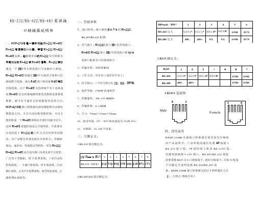
五、电源及防浪涌接地保护 1、外 接 电 源 HX SP - 2 1 0 8B 接 口 转 换 器 可 以 采 用 产 品 已 配 的 9V 电 源 适 配 供 电 , 也 可 以 从 其 它 直 流 电 源 或 设 备 供 电 , 供 电 电 压 力 +9V, 电 流为 100Ma。 2、浪 涌 接 地 保 护 : 普 通 的 接 口 转 换 器 没 有 配 备 大能量的保护装置,由于线路感应在接口 数据线上的瞬态高压,试图从设备的最小电 阻路径释放能量到地线。因此容易造成接口 器件的损坏。接口转换器在使用过程中为了 保证通信的安全可靠接地避免悬空。
发送负T- 发送正 T + 接收正 R+ 接收负R- GND
RS-485 定义
485-
485+ N L
N L GND
6 FCN FCN
3.RJ45 脚定义:
RJ45
1
2
3
4
5
6
RS-422
发送正T+ 发送负T- 接收正R+ 接收负R-
GND GND
RS-485 485- 485+
GND GND
4.RJ454 连接图
三、引脚定义:
1.RS-232 端引脚定义:
D B 9Female(PI N) 1 2 3 4 5 6 7 8 RS-232(DCE) D C D TXD R XD D TR G N A D SR R TS C TS
RS232串口使用说明
串口通讯--接口电路
能够完成上述“串<- ->并”转换功能的电路,通常称为“通用异步收 发器” (UART:Universal Asynchronous Receiver and Transmitter), 典型的芯片有:Intel 8250/8251,16550。
波特率
波特率 (bps) 110 300 1200 2400 4800 9600 1 号电缆传输距离(英尺) 5000 5000 3000 1000 1000 250 2 号电缆传输距离(英尺) 3000 3000 3000 500 250 250
RS-232C的接口信号 RTS CTS
• 请求发送(Request to send-RTS)——用来表示DTE请求 DCE发送数据,即当终端要发送数据时,使该信号有效 (ON状态),向MODEM请求发送。它用来控制 MODEM是否要进入发送状态。
• 允许发送(Clear to send-CTS)——用来表示DCE准备 好接收DTE发来的数据,是对请求发送信号RTS的响应 信号。当MODEM已准备好接收终端传来的数据,并向 前发送时,使该信号有效,通知终端开始沿发送数据 线TxD发送数据。
数据位与停止位
• 数据位:1位、2位
• 停止位:1位、1.5位、2位
流控制
.流控制在串行通讯中的作用 解决丢失数据的问题 .硬件流控制 硬件流控制常用的有RTS/CTS(请求发送/清除发送) 流控制和DTR/DSR(数据终端就绪/数据设置就绪)流 控制 .软件流控制
一般通过XON/XOFF来实现软件流控制。
• 在RTS、CTS、DSR、DTR和DCD等控制线上: • 信号有效(接通,ON状态,正电压)=+3V~+15V
RS232RS485串口服务器技术配置手册

RS232RS485串口服务器技术配置手册RS232/RS485串口服务器技术配置手册(Ver3.0)一、技术特点及应用方式 (3)1、产品技术特点 (3)2、应用方式 (4)二、RS232/RS485服务器配置方式 (5)1、使用VSPM虚拟串口软件的T elnet管理器 (5)2、使用Windows超级终端进行参数管理 (7)3、通过串口服务器管理端口进行管理 (10)三、服务器参数配置 (13)1、默认管理口令 (13)2、主菜单功能列表 (13)3、配置端口 (14)4、配置查看系统参数 (18)5、安全参数配置 (20)四、技术要点及应用 (22)1、RS232/RS485端口参数配置 (22)2、TCP/IP传输 (22)3、UDP广播传输 (23)4、NAT环境配置 (24)5、串口服务器配对应用 (26)6、RS232服务器的端口性能及参数 (28)7、商用级RS232串口服务器硬件连接 (28)8、工业级RS232以太网服务器硬件连接 (28)9、RS485串口服务器的端口性能及参数 (29)10、商用级RS485串口服务器硬件连接 (29)11、工业级串口服务器RS485硬件连接 (30)五、产品定制 (31)一、一、技术特点及应用方式技术特点及应用方式1、产品技术特点产品技术特点高性能的硬件结构采用16C554系列4串口扩展芯片。
-每串口在硬件级具备16个字节的FIFO 收/发缓冲。
高速低功耗RISC 处理器。
内置看门狗及掉电保护功能。
先进的软件结构使用嵌入式实时操作系统。
环式缓冲技术,在重负载下确保性能稳定。
网络支持网络接口-支持10Mbps RJ45以太网,TCP/IP 协议。
内建IP 认证模块-允许用户设定8个认证IP,不在此范围的IP 将被拒绝访问。
3种工作模式支持Server、Client 和UDP 广播模式。
支持NAT 环境-可以支持静态NAT 及持动态NAT管理特性支持Telnet 协议。
红狮控制Red Lion Controls RS-232 GCM232串行转换模块说明书

!ALLOWS COMMUNICATIONS BETWEEN RS-232 CONTROL EQUIPMENT AND RLC PRODUCTS WITH 20 mA SERIAL COMMUNICATIONS OPTION!ISOLATED 20 mA SERIAL COMMUNICATIONS!FULLY ENCLOSED SCREW-TOGETHER DURABLE PLASTIC CASEDESCRIPTIONThe GCM232 Serial Converter Module provides the capability of interfacing Red Lion Controls products with 20 mA current loop serial communications option to most equipment with RS-232 communications. The isolated 20 mA current loop connections in the GCM232 allows multiple modules to be wired into the serial loop. Data format of the RS-232 equipment must be the same as the Red Lion Controls product (Reference the serial communications section of the appropriate manual for more details).An external +12 VDC power source is required to power the GCM232module. Some Red Lion Controls products have a +12 VDC output which can be used (Note: Reference appropriate manual to ensure +12 volt output has enough current capability). The external power source and isolated 20 mA serial communications loop connections are made via a 6 position terminal block located inside the module. A 680Ωcurrent limiting resistor is provided to obtain the source current for the Serial Current Loop. Connections for the RS-232 are made via a 25-pin female D-type connector.SAFETY SUMMARYAll safety related regulations, local codes and instructions that appear in the manual or on equipment must be observed to ensure personal safety and to prevent damage to either the instrument or equipment connected to it. If equipment is used in a manner not specified by the manufacturer, the protection provided by the equipment may be impaired.SPECIFICATIONS1. POWER : + 9 to 28 VDC @ 30 mA max.Power supplies must be Class 2 or SELV rated.2. RS-232 VOLTAGES :Receive Data Pin 2: ± 30 VDC max., mark condition <0.8 VDC space condition > 2.4 VDC.Transmit Data Pin 3: mark condition = -10 VDC (typ). space condition = +10 VDC (typ).3. 20 mA CURRENT LOOP :SO - Output Transistor Rating: V max = 25 VDC,V sat = 1 VDC max @ 20 mA.SI - Input Diode Rating: VF = 1.25 VDC typ , 1.5 VDC max @ 20 mA.(Note: Reverse polarity protection at SI diode)4. MAXIMUM CABLE LENGTH :RS-232 cable : 50 Ft.20 mA current loop : 4000 Ft.5. BAUD RATE : 9600 max.6. ENVIRONMENTAL CONDITIONS :Operating Temperature : 0 to 50°C Storage Temperature : -40 to 80°COperating and Storage Humidity : 85% max. (non-condensing) from 0°C to 50°C.Altitude : Up to 2000 meters7. CERTIFICATIONS AND COMPLIANCES :SAFETYIEC 1010-1, EN 61010-1:Safety requirements for electrical equipment for measurement, control, and laboratory use, Part 1.EMC EMISSIONS :Meets EN50081-1: Residential, Commercial and Light Industry CISPR 22 Radiated and conducted emissions EMC IMMUNITY :Meets EN 50082-2: Industrial Environment.ENV 50140 - Radio-frequency radiated electromagnetic field 1ENV 50141 - Radio-frequency conducted electromagnetic field 1EN 61000-4-2 - Electrostatic discharge (ESD)2EN 61000-4-4 - Electrical fast transient/burst (EFT)3Notes:1. For operation without loss of performance:Install power line filter, RLC #LFIL0000 or equivalent.I/O cables routed in metal conduit connected to earth ground.2. Anti-static precautions should be observed before handling the device.3. For operation without loss of performance:Install power line filter, RLC#LFIL0000 or equivalent.Refer to EMC Installation Guidelines section of the manual for additional information.8. DIMENSIONS : 0.99" H x 2.10" W x 4.32" L25.2 mm H x 53.4 mm W x 109.8 mm L9. Shielded cable must be used, connect shield drain wire to earth ground.MODEL GCM232 -SERIAL CONVERTER MODULE (RS-232C/20 mA CURRENT LOOP)ORDERING INFORMATIONCAUTION:Read complete instructions prior to installation and operation of the unit.EMC INSTALLATION GUIDELINESAlthough this unit is designed with a high degree of immunity to ElectroMagnetic Interference (EMI), proper installation and wiring methods must be followed to ensure compatibility in each application. The type of electrical noise, source or coupling method into the unit may be different for various installations. In extremely high EMI environments, additional measures may be needed. Cable length, routing and shield termination are very important and can mean the difference between a successful or a troublesome installation. Listed below are some EMC guidelines for successful installation in an industrial environment.1. DC power to the unit should be relatively clean and within the specifiedlimits. Connecting power to the unit from circuits that power inductive loads that cycle on and off, such as contactors, relays, motors, etc., should be avoided. This will reduce the chance of noise spikes entering the DC power connection and affecting the unit.2. The shield (screen) pigtail connection should be made as short as possible.The connection point for the shield depends somewhat upon the application.Listed below are the recommended methods of connecting the shield, in order of their effectiveness.a. Connect the shield only at the unit to earth ground (protective earth).b. Connect the shield to earth ground at both ends of the cable, usually whenthe noise source frequency is above 1 MHz.c. Connect the shield to common of the unit and leave the other end of theshield unconnected and insulated from earth ground.3. Never run Signal cables in the same conduit or raceway with AC power lines,conductors feeding motors, solenoids, SCR controls, and heaters, etc. The cables should be run in metal conduit that is properly grounded. This is especially useful in applications where cable runs are long and portable two-way radios are used in close proximity or if the installation is near a commercial radio transmitter.4. Signal cables within an enclosure should be routed as far away as possiblefrom contactors, control relays, transformers, and other noisy components.5. In extremely high EMI environments, the use of external EMI suppressiondevices, such as ferrite suppression cores, is effective. Install them on Signal cables as close to the unit as possible. Loop the cable through the core several times or use multiple cores on each cable for additional protection. Install line filters on the power input cable to the unit to suppress power line interference. Install them near the power entry point of the enclosure. The following EMI suppression devices (or equivalent) are recommended:Ferrite Suppression Cores for signal cables:Fair-Rite # 0443167251 (RLC #FCOR0000)TDK # ZCAT3035-1330ASteward #28B2029-0A0Line Filters for input power cables:Schaffner # FN610-1/07 (RLC #LFIL0000)Schaffner # FN670-1.8/07Corcom #1VR3Note:Reference manufacturer’s instructions when installing a line filter. 6. Long cable runs are more susceptible to EMI pickup than short cable runs.Therefore, keep cable runs as short as possible.INSTALLATION ENVIRONMENTThe unit should be installed in a location that does not exceed the maximum operating temperature and provides good air circulation. Placing the unit near devices that generate excessive heat should be avoided. InstallationThe power and 20 mA current loop connections should be made with 24 gauge, multi-conductor, shielded cable. Wire insulation should be stripped to approximately 1/4 inch (stranded wires should be tinned with solder). Accessing the terminal block is accomplished by removing the four screws and nuts that hold the two halves together. Connect the power and 20 mA loop wires to the appropriate terminal block pins, and route the cable through the groove at the rear of the module.Install the two screws and saddlewashers into the slots at the 25-pinD-connector.The two halves are placedtogether, then secured with the fourscrews and nuts. Refer to figure 1below for assembly.FIGURE 1TYPICAL POWER AND 20 mA LOOP CONNECTIONSFIGURE 2TYPICAL CONNECTION FOR MULTIPLE UNITSFIGURE 3 TROUBLESHOOTINGFor further technical assistance, contact technical support at the appropriate company numbers listed.LIMITED WARRANTYThe Company warrants the products it manufactures against defects in materials and workmanship for a period limited to one year from the date of shipment, provided the products have been stored, handled, installed, and used under proper conditions. The Company’s liability under this limited warranty shall extend only to the repair or replacement of a defective product, at The Company’s option. The Company disclaims all liability for any affirmation, promise or representation with respect to the products.The customer agrees to hold Red Lion Controls harmless from, defend, and indemnify RLC against damages, claims, and expenses arising out of subsequent sales of RLC products or products containing components manufactured by RLC and based upon personal injuries, deaths, property damage, lost profits, and other matters which Buyer, its employees, or sub-contractors are or may be to any extent liable, including without limitation penalties imposed by the Consumer Product Safety Act (P.L. 92-573) and liability imposed upon any person pursuant to the Magnuson-Moss Warranty Act (P.L. 93-637), as now in effect or as amended hereafter.No warranties expressed or implied are created with respect to The Company’s products except those expressly contained herein. The Customer acknowledges the disclaimers and limitations contained herein and relies on no other warranties or affirmations.。
串口继电器模块说明书

串口继电器模块介绍4路输入4路输出模块一、性能说明1、采用RS485或RS232 MODBUS RTU标准通讯协议,可与PLC、组态软件、触摸屏等进行组网2、MODBUS协议支持较多的功能码命令,及错误命令提示3、模块地址号可以软件任意设置0~255范围4、具有断线检测功能,避免主机故障后负载一直处于不受控状态5、通讯接口电路采用防雷、抗干扰设计6、4路光电隔离数字量输入和4路继电器数字量输出7、广泛用于工业现场设备的数字量信号采集及控制二、技术参数1、数字量输入通道 4路光耦隔离,共正极2、数字量输出通道 4路继电器输出,触点容量250V10A3、通讯协议 RS232或RS485传输,MODBUS RTU标准协议4、工作温度范围 -25~70℃5、模块供电电源 DC24V(可订做DC12V)6、隔离保护 1500VDC7、引线接口 15A300V插拔式接插件8、安装方式标准DIN导轨安装或四角螺丝固定安装9、外形尺寸 115×103×40mm(长宽高)三、外形与接线图(模块外形)(输出输入口内部逻辑图)(接线图)四、通讯协议1、串口参数设置:a)波特率9600bpsb)数据位8位c)校验位无(N)d)停止位1位e)默认模块地址号为1f)MODBUS RTU通讯方式2注:单帧数据长度不能超过30个字节,读取保持寄存器时最多一次可读取10个字的参数值3说明:a)寄存器地址0,模块的地址号,默认为1在组网时,RS485总线上从设备的地址号。
建议在修改模块地址号时,网络上只有一个模块,修改立即生效。
当记不清模块地址号时,可以用0地址号进行读写访问。
b)寄存器地址1,断线检测,默认为0当网络中主设备异常退出、死机、断线、故障时,模块检测不到数据帧后,等待延时达到寄存器1设置值时,模块自动关断输出继电器,避免负载一直处于不受控状态。
在简单的控制电路(如控制一盏电灯),主机只是单次发一帧控制命令,然后一直处于空闲等待状态,断线检测就像延时开关一样,到达延时时间后自动关断输出继电器,反而不便,此时应该设置寄存器1的值为0,无此功能。
硬件手册:双LPT RS232串行口卡手册说明书

Hardware ManualDual LPT & RS2321.2 Edition February 1999Guarantee.FULL 36 MONTHS GUARANTEE.We guarantee your Serial Port Card for a full 36 months from purchase, parts and labour, provided it has been used in the specified manner. In the unlikely event of failure return your interface to your Dealer, with proof of purchase, who will determine whether to repair or replace this product with an equivalent unit.COPYRIGHT.COPYRIGHT © 1985-1998.All rights reserved. No part of this hardware, circuitry or manual may be duplicated, copied, transmitted or reproduced in any way without the prior written consent of the Manufacturer.Serial Solutions is supplied to you byACKNOWLEDGEMENTS.IBM, COMPAQ, Hewlett Packard, H.P. and EPSON are trademarks of the relevant companies. Windows is a trademark of Microsoft.PCI DUAL LPT & RS232 MANUALOUTLINE CONTENTSChapter 1 - Optional Serial Solution Software. Chapter 2 - PCI DUAL LPT & RS232 Specifications. Chapter 3 - PCI DUAL LPT & RS232 SoftwareConfiguration Guide.The Layout Of This ManualChapter 1 - Serial Solution Software, is an overview of the optional, ideal companion software package for our range of serial port cards. Buy it from your dealer now!Chapter 2 - PCI DUAL LPT & RS232 Specifications, gives details of the PCI DUAL LPT & RS232 specifications, details of how to install the optional parallel port and shows you how to install your PCI Dual LPT & RS232 Card.Chapter 3 - PCI DUAL LPT & RS232 Software Configuration Guide, shows you how to configure your operating system to successfully allow trouble free operation of your PCI Dual LPT & RS232 Card. Installation procedures are for Windows 95/98.PCI DUAL LPT & RS232 MANUAL (1)CHAPTER 1 (3)SERIAL SOLUTIONS SOFTWARE (3)Introducing Serial Solution Software (3)Serial Solutions For DOS (4)Serial Solutions For Windows 3.x (6)Serial Solutions For Windows 95 (6)Complete Documentation and Technical Backup (7)CHAPTER 2 (8)PCI DUAL LPT & RS232 SPECIFICATIONS (8)Introduction (8)PCI Dual LPT & RS232 Card Features (8)Configuring The PCI DUAL LPT & RS232 Card (10)Parallel Printer Port Configuration (10)Hardware Installation (11)Problems! (12)Installing 2nd parallel and Serial Ports (12)Chapter 3 (14)PCI Dual LPT AND RS232 SOFTWARE CONFIGURATION GUIDE (14)Introduction (14)Installing Ports In Microsoft Windows 95 & 98 (14)Card Settings In Windows 95 & 98 (17)Port Settings In Windows 95 & 98 (18)CHAPTER 1SERIAL SOLUTIONS SOFTWARE.Introducing Serial Solution Software.The perfect partner for any Serial Port is Serial Solutions Software! Serial Solutions is a fully featured suite of programs designed to squeeze the most from PC serial communications.Serial Solutions is made up of the following components: - Serial Solutions for DOSSerial Solutions for Windows 3.xSerial Solutions for Windows 95Serial Solutions for Windows NTAll the Serial Solutions drivers have the following features: -•Drivers for PC FIFO UARTs e.g. 16550 as well as the new improved 32 byte 16650, 64 byte 16750 and 128 byte 16950 UARTs•Support for any mix of RS232, RS422 and RS485 handshake schemes.•Support for wider range of Baud rates and for more than 4 serial ports.Serial Solutions For DOS.Serial Solutions for DOS consists of the following programs: -NewCOM.sys A device driver, it supports COM1 to COM16,allowing 16 serial ports to be used under DOS.It also includes an interrupt handler forenhanced performance with user definablebuffer sizes. Accessible from all DOSlanguages, it is the heart of the Serial Solution.It has extensive handshaking support,implementing both hardware handshakingusing any combination of the DTR, DSR, CTS,RTS, and DCD lines, and a software handshakeusing the XON/XOFF protocol.NewCOM24.sys A device driver providing support for 24 ports. NewCOM32.sys A device driver providing support for 32 ports. NewMode.exe A replacement for the DOS ’mode com...’command. NewMode is used to set the serialparameters, including the port address, IRQline used, the baud rate, parity and data andstop bit options.e.g. NEWMODE COM5:38400,E,7,1 01A0 7Baud rates supported are from 110 baud to115,200 baud! Included is a very handy querymode that reports the settings of the variousserial ports. Flexible and fast!EASY programs.The EASY disk contains short, simple tounderstand and use EASYBAS, EASYC andASYPAS programs, providing straightforward, file type I/O to serial ports with debuginformation. Use these FIRST, base yoursample applications on them.Source code, make files and compiled ready torun programs supplied.TERM programs A suite of larger terminalemulation programs written in C (Cterm),Assembly language (Aterm), Pascal (Pasterm),BASIC (BASterm) and FORTRAN (FORterm)show how to access the NEWBIOS routines aswell as the simple file I/O to ports. Theycontain many lines of code and are thus harderto grasp. They demonstrate in depth serial portprogramming in a variety of languages but theyare also useful tools for using serial devices. Comtest.exe Comtest is a short but invaluable program that isused to check that the serial port at a particularI/O address is functioning correctly and isconnected to the particular IRQ line. The programcorrectly identifies the UART type e.g. non-FIFO, 16550 FIFO, 16550AF FIFO and theimproved 16650 32 byte FIFO and 16750 64 byteFIFO’s. By employing the built in loop backcapability of the PC serial port chip, a full test ofthe baud rate generator, transmitting and receivingbuffer, parity enable and start stop bit isperformed. There is no need for a second serialport or a cable when using this utility.Serial Solutions For Windows 3.xSerial Solutions for Windows 3.x works with Windows 3.0, 3.1 and 3.11 as well as Windows For Workgroups 3.11.Serial Solutions for Windows 3.x consists of the following programs: -Setup.exe The install routine for the package.Port.DLL Enhanced Control Panel applet. Allowsconfiguration of extra serial ports from theWindows Control Panel. Supports single as wellas multiport cards using shared interrupts. BbLynx.drv Replacement for COMM.DRV.LynxAPI.dll Enhancement to the Windows Comms API’sallowing support for more than 9 ports.Term.exe Terminal program.EasyCWIN C source code, project files and ready to run.exeprogram for an easy to understand Windowsterminal program. Learn how to write Windowscomms apps correctly the easy way.Serial Solutions For Windows 95.Windows 95 has an improved communication API and directly supports up to 255 ports. Our Windows 95 driver supports the shared interrupt mechanism used on our multiport cards. Serial Solutions for Windows 95 consists of the following programs: -ISA.INF PCI.inf SSDRVS.INFSSCARDUI.DLL SSPORTUI.DLLSSSENUM.VXD SSM485.VXD SSMULT.VXD SSV485.VXD SSVEL.VXD The information files to aid the installation process "Have Disk...…The DLL’s and…...the virtual device driver providing theshared interrupt handler.Complete Documentation and Technical Backup.We believe in supplying complete documentation with every package we sell. The Serial Solution Software Package is no exception, it has an attractive CD ROM containing all required documentation. A complete technical backup service is available to ensure that you get the maximum performance out of your investment.PCI Dual LPT & RS232 Software ConfigurationCHAPTER 2PCI DUAL LPT & RS232SPECIFICATIONSIntroduction.This chapter details the specifications of the PCI Dual LPT & RS232 Card and explains how to add the optional serial/parallel port to the card.This half-sized card will work happily in any PCI 2.0 or greater compliant PC compatible.PCI Dual LPT & RS232 Card Features.•One or two Centronics Parallel printer ports, PC compatible •One or two independent 9 pin D RS232 Serial ports.•Reliable communications up to 50 feet, 15m, and beyond!•16550 FIFO provides 16-byte input and 16-byte output buffer on each port.•Maximum baud rate of 115,200 Baud.•Word length of 5, 6, 7 or 8 bits.•Even, Odd, None, Mark or Space parity options.• 1 start bit always sent.•1, (1.5 for 5 bit data word length) or 2 stop bits.•Clock input of 1.8432 MHz•100% PC Compatible serial port TI 16C550, up to 115,200 baud.•Full modem control TXD, RXD, DSR, DCD, DTR, RTS, CTS and RI signals.•Fully double buffered for reliable asynchronous operation.•High-speed integrated circuitry ensures operation with fast PC’se.g. 500MHz Pentium II WITHOUT extra wait states.Figure 2-1. PCI DUAL LPT & RS232 Card Layout.PCI DUAL LPT & RS232 Specifications:Dimensions: 4.8 x 3.5 in, 120 x 90 mmI/O Connection: Serial Port 1: 9 pin Male D type.Optional Serial Port 2: 9 pin Male D type.(via flylead with PC bracket.)LPT port: Parallel Port 1: 25 pin Female D typeOptional Parallel Port 2 : 25 pin Female Dtype (via flylead with PC bracket.)Configuring The PCI DUAL LPT & RS232 Card.PCI cards, by definition, require no hardware configuration and can be installed "directly from the box".Figure 2-2. 9 Pin D Connector Port Pinouts.Parallel Printer Port Configuration.On the PCI Dual LPT & RS232 Card, the parallel printer port is the lower 25-pin connector on the card.Figure 2-3 Printer Port Pin Outs.ÂREPÂ& Â@7V7ÂUAVÂTA7@a @UT REPÂ( Â9HA7TÂVQÂUAP@ 9VU VT7PUIEVVA@Â@7V7 V`@TA9AEXA@Â@7V7 T`@REPÂ' ÂTASWAUVÂVQÂUAP@ TVU REPÂ) ÂTEPCÂEP@E97VQT TEHardware Installation.NOTE: Always turn the computer OFF before installing or removing any interface board..STEP 1: Before the PC card can be installed the power to the PC must be switched off and for additional safety it is recommended that the mains supply plug is removed from the PC itself.STEP 2: Remove the case.Figure 2-4. Removing Blanking CoverSTEP 3: Choose an empty appropriateexpansion slot. Remove the blanking coverprotecting the slot on the PC back panel.KEEP the blanking cover screw safely forlater (Figure 2-4).Figure 2-5. Inserting The PC Serial Card.STEP 4: Now insert the PC Serial card inthe available slot. Be careful to ensure thatthe gold plated PCB fingers fits neatly intothe I/O expansion connector. Press downfirmly but evenly on the top of the PC Serialcard (Figure 2-5).STEP 5: The D connectors should fit neatly through the slot’s aperture to the outside world. NB. Use the screw kept back from the blanking cover to screw the PC Serial retaining bracket into the PC back panel housing.STEP 6: Now replace the system units cover by carefully sliding it down and back over the system unit. Replace the cover mounting screws.STEP 7: After attaching all the monitor and keyboard cables, power up the PC. Do not forget the mains power cable!The PC should power on in the normal way.Problems!If the system fails to power up normally check the following.:i.)Ensure that the PC Serial card is installed correctly.ii.)Ensure that other cards in the PC have not been upset. iii.)Ensure that the power is connected and the PC is switched ON!n If all these have been checked and the PC still does not power up then there is probably a conflict of I/O address between the PC Serial card and another board in the PC. Ask your dealer to check thisInstalling 2nd parallel and Serial PortsSupplied with the PCI DUAL LPT & RS232 card is a seperate bracket containing a 9 pin serial port connector and a 25 pin parallel port connector. Both connectors have a ribbon cable attached terminating in an IDC style plug.Each of these cables have 1 of the wires coloured red. Where this red wire terminates at the plug there is an inverted triangle, this denotes PIN1.The PCI Dual LPT & RS232 card has 2 "headers" on the board labelled PRINTER2 and SERIAL2 located along the top edge. Each of these "headers" has a white arrow which points to PIN1.Holding the cable assembly at right angles to the board (As shown in fig 2-6), ensuring that PIN1 on each plug mates with PIN1 on the "header", press each plug down evenly and firmly until resistance is felt - The extra ports have now been plugged in. Figure 2-6 Installation of Serial Port 2.Chapter 3PCI DUAL LPT AND RS232 SOFTWARE CONFIGURATIONGUIDEIntroduction.This section contains the installation procedures of the PCI Dual LPT & RS232 card, with the Windows 95/98 operating system.The setup procedures in this chapter assume that your PC has only one serial port present.Installing Ports In Microsoft Windows 95 & 98.Although covering the installation of the PCI Dual LPT & RS232 into the Windows 95 operating system, the procedure is also valid, with only minor differences, in the Windows 98 Operating System. The Windows 95 environment now supports up to 255 standard serial ports, RS232, RS422, RS485 etc.To obtain a trouble free mix-and-match of the COM ports:•Switch off your computer, insert your PCI Dual LPT & RS232 card into a free PCI slot, as described in the section "Hardware Installation" in Chapter 2, and switch your computer on again.•During the booting process, Windows 95 will detect PCI Dual LPT & RS232, but will display it simply as a "PCI CARD", and you will briefly see a message box to this effect.•Windows will then display the "Update Device Driver Wizard", which asks you to “insert any disk which came with the PCIcard”. Insert the Windows 95 installation disk into an appropriate drive and click 'Next'.•The Wizard should then display something similar to following:•Click Finish.• A "Copying Files…" window should now appear. Click 'OK' when it asks you to insert the disk.•After copying the file, Windows 95 will then detect each of the serial ports in turn and install them as communications ports; in the case of the PCI Dual LPT & RS232 it will also 2 parallel ports, and then installs them as printer ports.When the "Device Manager" is viewed:•PCI Dual LPT & RS232 will appear under the "Multi-function adapters" branch, 2 Communications Ports and 2 Printer Ports will appear under the "Ports (COM & LPT) branch."For most users who have 4 or less COM ports the new ports will appear as COM5 and COM6, as pictured below; for users with more than 5 COM ports the new ports will appear as the first available COM ports.•Select the PCI Dual LPT & RS232 card from the "Multi-Function Adapter" entry in Device Manager and click on properties to view the cards general properties; clicking on the Serial Solutions tab produces:In this window, the COM (and LPT) port assignment may be changed, simply by selecting a new COM port value from the pull down menu relevant to the port. However, COM port usage other than those for the PCI Dual LPT & RS232 card itself are not checked, so it is advisable to first check which COM ports are in use -port availability can be checked by viewing the Device Manager. This process also applies to LPT assignment, and LPT port usage can also be viewed from the Device Manager.. NOTE: At time of print there exists no facility within the driver software to disable any of the card’s ports.Double clicking on a Communications Port that belongs to a PCI Dual LPT & RS232 card will display general properties window for that port (in this case COM2). Selecting the Port Settings tab produces:Settings available in these windows are:1.Baud Rate - determines the baud rate at which theselected port operates.•the maximum value of operation is 115,200, even though the maximum value selectable is 921,600 -this is due to standard Windows COM port driversbeing used.2. Data Bits.3. Parity.Change to suit remote device.4.Stop Bits.5. Flow Control.6. Advanced - clicking on this will display the followingwindow:Settings available in this window are:•Use FIFO Buffers - turns the selected ports FIFO buffer on or off. It is strongly recommended thatthe FIFO for both ports is left enabled.•Receive Buffer - These settings allow the selection of a receiver FIFO trigger setting. Selecting a lowvalue will allow the interrupt to be servicedquicker, which is good for slow machines. If youhave a fast machine, setting a high value will giveyou more time for multi-tasking operations.•Transmit Buffer - These settings allow the selection of a transmitter FIFO trigger setting.Selecting a low value will send fewer data-bytesper interrupt, and this is recommended if you arecommunicating to a slower machine. Selecting ahigh value will send more data-bytes per interrupt,and will give more time for multi-taskingoperations.•Defaults: when clicked this button restores the advanced settings for the selected port to:Use FIFO Buffers: On (Checked)Receive Buffer:High (14)Transmit Buffer:High (14)7.Restore Defaults - when clicked, resets the selectedCOM port to the following values:Baud Rate:9600Data Bits:8Parity:NoneStop Bits:1Flow Control:Xon / XoffINDEXIndex16450 / 16550......................................................................3, 5, 8 asynchronous. (8)baud / baud rate....................................................................4, 5, 8 buffer / buffered...................................................................4, 5, 8 cable.......................................................................................5, 12 Changing COM numbers in Windows 95.. (17)command (4)Configuring ports in Windows 95 & 98 (18)connectors (11)CTS.........................................................................................4, 8 data word length (8)DCD........................................................................................4, 8 DSR.........................................................................................4, 8 DTR.........................................................................................4, 8 emulation. (5)FIFO....................................................................................3, 5, 8 handshake................................................................................3, 4 installation (14)Installing Ports In Windows 95 & 98 (14)interrupts (6)loop back (5)mode (4)modem (8)Optional Serial / Parallel Port (9)Parallel Printer Port (10)parity.......................................................................................4, 5 port..........................................................................................4, 5 port / ports................................................................1, 8, 9, 10, 14 ports...................................................................................3, 4, 5, 6 Print / Printer.........................................................................8, 10 protocol. (4)RI (8)RS232........................................................................1, 3, 8, 9, 10 RS422 / RS485. (3)RTS.........................................................................................4, 8 RXD.. (8)serial port..................................................................1, 3, 4, 5, 6, 8 shared interrupt. (6)speed (8)TXD (8)Windows..........................................................................2, 4, 3, 6。
HDOM -232用户手册说明书

HDOM-232 User Manual 1 About HDOM-232RS-232 is the one of popular serial communication interfaces. In order to use the computer to commission and monitor the drive conveniently for customers, our company supplies HDOM-232.HDOM-232 is the optional module of drive, which converts RS-232 signal to RS-485 signal. It meets SELV. Please read the User Manual carefully before use, to avoid personal injury and property damage due tomis-operations.1.1 Function and features1.1.1 FunctionHDOM-232 can realize the isolate transformation bi-directly betweenRS-232 and RS-485.HEDY drive can realize high speed data communication with computers through HDOM-232.1.1.2 Features1)Light and small, convenient for the user to installation and use;2)High stability, meet using requirements of various HEDY drive model;3)Excellent protection performance, realized the reinforced insulationbetween RS-232 port and RS-485 port, which ensure the personalsafety for users.2 Technical data3 Usage3.1 Relationships of connector3.1.1 Connector diagram图3-1 Connector diagram3.1.2 Connector1)Connector with computer1569Figure 3-2 RS-232 DB9 connector2)Connector with drive RJ4581Figure 3-3 RJ45 connector3.2 Operation steps1)Open the terminal cover, and remove protective cover on RS-485 port;2)Connect one end of HDOM-232 to the computer RS-232 port, and theother to drive RS-485 port, as shown in figure 3-4 ;3)Cover up the terminal cover and fix;4)Cooperate with HDsoft perform communications test.Note:1)The connection between HDOM-232 RJ45 port and drive must beoperated by professionals;2)RS-232 of HDOM-232 must be connected to computer DB9 portdirectly. It is forbid using USB-RS-232 switches between thecomputer and USB-232 connector; otherwise the computer anddrive cannot communicate.computerFigure 3-4 Connection diagram4 TroubleshootingWhen HDOM-232 can't realize communication between the computer anddrive, please check according the guide as below:1)Check whether the cable connected correctly;2)Check the computer port, baud rate, communication mode settings;3)Check communication related function code settings.5 Service agreementThe warranty period of HDOM-232 is 18-month, within which periodHEDY conducts free maintenance and repairing to the product that has anyfault or damage under the normal operation conditions. The start time ofwarranty period is the delivery date of the product. Even within 18 months,maintenance will also be charged in the following situations:1)Damages incurred to the product due to mis-operations, which are notin compliance with the User Manual;2)Damages incurred to the product due to mis-operations, which are notpermitted by the factory supplier, such as modify or remove devices;3)Damages incurred to the product due to unforeseeable natural disasters,such as fire, flood, earthquake, etc.。
2 路串口继电器使用说明书

2路串口继电器说明书适用产品系列/型号:LH-IO204;LH-IO204-232历史版本修订日期修订记录版本号修订人2021/10/20模版修订V1.0李世涛2021/10/26版本更新,修改错误V1.1李世涛2022/07/08错误修改V1.2李世涛2022/09/05固件及上位机更新1、上位机用了更美观的UI,增加了常用功能2、固件增加了断电记忆、校验位修改V2.0李世涛目录1.产品介绍 (4)1.1.产品简介 (4)1.2.工作模式说明 (5)1.2.1.正常模式 (5)1.2.2.闪开闪闭功能 (5)1.2.3.本机非锁联动模式 (6)1.2.4.本机自锁联动模式 (6)1.2.5.本机互锁模式 (6)1.2.6.双机非锁联动模式 (7)1.2.7.双机自锁联动模式 (7)2.规格参数 (9)3.产品尺寸 (11)4.通信协议与数据格式 (11)4.1.上位机软件下载 (11)4.2.设备通信配置 (11)4.2.1.拨码开关功能介绍 (11)4.2.2.软件地址的设定与读取 (12)4.2.3.波特率、校验位、断电记忆的设定与读取 (13)4.3.通信协议说明 (13)4.3.1.Modbus寄存器说明 (13)4.3.2.线圈寄存器地址表 (14)4.3.3.指令列表 (15)4.3.4.指令详解 (16)4.4.主动上报协议 (20)5.电气接线 (21)5.1.产品使用拓扑图 (21)5.2.产品接线端子定义 (22)5.3.产品输入接线图 (23)5.4.产品输出接线图 (25)6.产品维护保养 (26)6.1.设备使用环境 (26)6.2.常见问题与解决办法 (27)7.售后服务 (29)7.1.售后服务承诺 (29)7.2.免责声明 (29)7.3.联系方式 (29)用户须知使用前请详细阅读本说明书,并保存以供参考。
请遵守本说明书操作规程及注意事项。
在收到仪器时,请小心打开包装,检视仪器及配件是否因运送而损坏,如有发现损坏,请立即通知生产厂家及经销商,并保留包装物,以便寄回处理。
RS_232串口通信设计说明书
《 CPLD/FPGA 》课程设计报告题目: RS-232串口通信设计院(系):信息科学与工程学院专业班级:通信工程11 学生姓名:詹文魁学号:指导教师:吴莉老师2014年06 月 09 日至2014年 6 月 20 日华中科技大学武昌分校制RS-232串口通信设计课程设计任务书一、设计(调查报告/论文)题目RS-232串口通信设计二、设计(调查报告/论文)主要内容下述设计内容需由学生个人独立完成:1.理解电路原理图与工作过程;2.掌握RS-232电气特性;3.掌握RS-232通信原理及串口通信数据格式,并编程完成串行数据的发送、接收和显示;4.能正确处理编程与调试过程中所遇到的问题。
三、原始资料1. 通信与电子系统实验指导书;2. CPLD/FPGA实验箱。
四、要求的设计(调查/论文)成果1.程序结构合理,语言简洁,格式规范,注释详细;2. 掌握RS-232的工作机制与原理;3. 格式为:1位起始位,8位数据位,1位停止位,无奇偶校验位,波特率设定为300Baud。
能与计算机正常通信;4. 按要求完成课程设计报告,格式符合学校规范标准,字数不少于2000字。
五、进程安排第1天选题,课题讲解;第2-3天课题分析,完成设计方案;第4-6天软件编程;第7-8天软件调试,故障排查;第9天结果验收,评分;第10天撰写课设报告。
六、主要参考资料[1] 陈曦. 通信与电子系统实验指导书,武汉:华中科技大学武昌分校.[2] 谭会生.EDA技术及应用,西安:西安电子科技大学出版社,2010.[3] 潘松,黄继业.EDA技术与VHDL,北京:清华大学出版社,2009.指导教师(签名):20 年月日目录1. 课程设计的目的 (4)2. 课程设计题目描述和要求 (4)3. 课程设计报告内容 (4)3.1 课题设计方案及基本原理 (4)3.2 软件设计 (7)3.3 问题 (14)4.总结 (15)5.参考资料 (16)附录程序清单 (17)1.课程设计的目的:(1)学习RS-232串口通信数据结构,并编程完成串行数据的接收和显示。
Haiwell RS485 232 通讯扩展模块使用说明书

HaiwellRS485/232通讯扩展模块使用说明书一、产品型号及外观型 号 功率(24VDC)外形尺寸S01RS0.4VAH01RS 0.4VA H02RS 0.5VA30*95*82mm二、指示灯说明1、POW :电源指示灯,绿色。
常亮 - 电源正常;不亮 - 电源异常。
2、LINK : 模块与PLC 主机连接正常时常亮,模块与PLC 主机交互数据时闪烁。
3、RS232的0、1:指示通讯口0、1为RS232通讯方式,作主设备(Master )时发命令闪烁,作从设备(Slave )则回复数据时闪烁。
4、RS485的0、1:指示通讯口0、1为RS485通讯方式,作主设备(Master )时发命令闪烁,作从设备(Slave )则回复数据时闪烁。
三、产品环境规格项 目 环 境 规 格 温度/湿度工作温度:0~+55 ℃储存温度:-25~+70 ℃ 湿度:5~95%RH ,无凝露 抗振动能力 10~57Hz 振幅0.075mm ,57Hz~150Hz 加速度1G ,X 、Y 、Z 三轴方向各10次 抗冲击能力 15G ,持续11ms ,X 、Y 、Z 三轴方向各6次 抗干扰能力 DC EFT :±2500V耐压能力 AC 端子对地线端子间1500VAC ,1分钟 DC 端子对地线端子间 500VAC ,1分钟 绝缘阻抗 AC 端子对地线端子间500VDC ,5M Ω以上(所有输入/输出点对地间500VDC) 接地 第三种接地(不可与强电系统通用接地) 使用环境 防尘、防潮、防腐蚀、免受电击及外力冲击等环境隔离方式通道间无隔离,通讯接口与内部电源采用光电隔离四、模块功能说明通讯扩展模块是一款用于扩展串口通讯接口的模块。
一个通讯模块可扩展RS232或RS485口,具体选择通讯方式由模块的接线决定,无需设置参数。
一台主机最多可扩展3个通讯模块,即一个PLC 系统可同时带5个通讯口与不同的设备进行通讯(主机自带2个分别为RS232与RS485的通讯接口)。
- 1、下载文档前请自行甄别文档内容的完整性,平台不提供额外的编辑、内容补充、找答案等附加服务。
- 2、"仅部分预览"的文档,不可在线预览部分如存在完整性等问题,可反馈申请退款(可完整预览的文档不适用该条件!)。
- 3、如文档侵犯您的权益,请联系客服反馈,我们会尽快为您处理(人工客服工作时间:9:00-18:30)。
(HC-8-RS232/RS485)串口继电器模块使用说明书
产品特点
●DC12V1A供电
●控制驱动不带隔离
●通讯方式支持RS232\RS485
●自定义通信协议(可根据客户需要定制)
●采用导轨式安装方式
产品功能
●波特率9600 8 1
●支持单开、单关、全开、全关、部分开、部分关
主要参数
●触点容量10A/30VDC 10A/250VAC
●耐久性10万次
●数据接口RS232/RS485
●额定电压DC 9-12V
●电源指示1路红色LED灯指示
●通讯指示无
●输出指示LED灯指示
●温度范围工业级-40~85度
●通讯格式9600 N 8 1
●软件支持配套软件串口助手
接口简介如下:
●1、2、3对应继电器常闭、公共点、常开
●RS232接口采用DB9母头。
使用USB转串口线需要使用公头,使用串口线为直通串口
线
●电源为DC12V1A 指示灯为红色LED
控制电路接线图如下:
上位机软件界面:
●串口号可以在电脑的设备管理器里查看
●模块出厂地址为00
通信协议:
模块默认地址00 波特率9600 8 1 十六进制
AA5A000100FF 打开继电器1 AA5A000000FF 关闭继电器1
AA5A001100FF 打开继电器2 AA5A001000FF 关闭继电器2
AA5A002100FF 打开继电器3 AA5A002000FF 关闭继电器3
AA5A003100FF 打开继电器4 AA5A003000FF 关闭继电器4
AA5A004100FF 打开继电器5 AA5A004000FF 关闭继电器5
AA5A005100FF 打开继电器6 AA5A005000FF 关闭继电器6
AA5A006100FF 打开继电器7 AA5A006000FF 关闭继电器7
AA5A007100FF 打开继电器8 AA5A007000FF 关闭继电器8
AA5A008100FF 打开继电器9 AA5A008000FF 关闭继电器9
AA5A009100FF 打开继电器10 AA5A009000FF 关闭继电器10
AA5A00A100FF 打开继电器11 AA5A00A000FF 关闭继电器11
AA5A00B100FF 打开继电器12 AA5A00B000FF 关闭继电器12
AA5A00C100FF 打开继电器13 AA5A00C000FF 关闭继电器13
AA5A00D100FF 打开继电器14 AA5A00D000FF 关闭继电器14
AA5A00E100FF 打开继电器15 AA5A00E000FF 关闭继电器15
AA5A00F100FF 打开继电器16 AA5A00F000FF 关闭继电器16
AA5A00FF00FF 打开所有继电器AA5A00FE00FF 关闭所有继电器
AA5A00FC00FF 查询继电器状态返回 AA5A00FC00FF (FC后面的两个十六进制对应的两组8位二进制为十六个继电器的状态 1为打开,0为关闭)
AA5A00FD00FF 打开部分继电器
以下是对打开部分继电器的详解:
FD后面的一个十六进制为打开的指令
比如当发送的是AA5A00FD99FF的时候打开的是第1,4,5,8继电器。
99转换成二进制是10011001 其中1为打开 0为关闭。
第一位1对应的是1号继电器。
具体为把一个十六进制作为八个二进制用,对应八个继电器。
这种方式可以同时打开1到8个继电器。
常见问题解答:
1、最大控制电流多少A?
答:10A
2、RS232通信距离多少米?RS485通信距离多少米?
答:RS232通信距离理论15米(传输变慢)。
RS485通信距离理论1200米(具体和通信线的材质有关)
3、供电可以使用DC24V吗?
答:16路可以支持DC24V供电,需要给店家说明。
4、上位机界面可以修改吗?
答:可以修改。
提供C#和python两种语言的上位机程序和源代码。
也可以按照客户要求修改,需要收取一定的费用。
常见无法控制情况解答:
1、检查拨码开关是否在正确的位置,它采用8421编码,出厂是0,上位机软件需要设置为0进行控制。
2、如果买家自己选用的串口线,需要使用直连线,一公一母的接头。