honeywell-l50控制器操作说明
Honeywell 控制器的PID调节
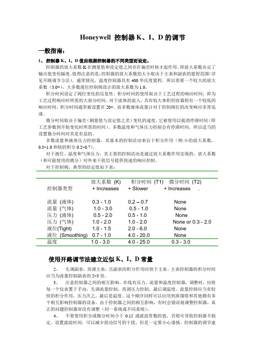
Honeywell 控制器K、I、D的调节一般指南:1、控制器K、I、D值应根据控制器的不同类型而设定。
控制器的放大系数K在测量值和设定值之间存在偏差时候才起作用,即放大系数决定了输出值变化幅度。
值得注意的是:控制器的放大系数的大小取决于主表和副表的量程范围(详见开路调节方法)。
通常情况,温度控制器具有400华氏度量程,所以需要一个较大的放大系数(3.0+),大多数液位控制阀设计的放大系数为1.0。
积分时间设定了阀位变化的反复性。
积分时间的使用取决于工艺过程的响应时间,即为工艺过程响应时所需的大部分时间。
对于流体的流入,具有较大体积的容器则有一个较低的响应时间,积分时间通常被设置在20+。
而多数液体流量计对于控制阀位的改变响应非常迅速。
微分时间取决于偏差(测量值与设定值之差)变化的速度,它被使用以抵消停滞时间(即工艺参数到开始变化时所需的时间)。
多数温度和气体压力控制会有停滞时间,所以适当的设置微分时间对其是有益的。
多数流量和液体压力控制器,其基本的控制活动来自于积分作用(例:小的放大系数,0.3~1.0和快的积分0.2~0.7)。
对于液位、温度和气体压力,其主要的控制活动是通过放大系数作用实现的。
放大系数(和可能使用的微分)对外来干扰信号提供快速的响应控制。
对于控制阀,典型的给定值如下表:放大系数(K) 积分时间(T1) 微分时间(T2) 控制器类型+ Increases + Slower + Increases .流量(液体) 0.3 - 1.0 0.2 – 0.7 None流量(气体) 1.0 - 3.0 0.5 - 1.0 None压力(液体) 0.5 - 2.0 0.5 - 1.0 None压力(气体) 1.0 - 2.0 1.0 - 2.0 None or 0.3 - 2.0 液位(Tight) 1.0 - 1.5 2.0 - 6.0 None液位(Smoothing) 0.7 - 1.0 4.0 - 20.0 None温度 1.0 - 3.0 4.0 - 25.0 0.3 - 3.0使用开路调节法建立近似K、I、D常量2、先调副表,再调主表,且副表的积分作用应快于主表。
Honeywell 蜂鸟水热器控制器安装说明书

How to Install the Gas Water Heater Controller for theHoneywell gas valve in 3 Easy StepsDO NOT PLUG THE GWHC IN PRIOR TO INSTALLATIONInstallation Step 1Locate the “gas control valve” in the lower center of your gas hot water heater. Turn the “Gas Control Knob” l ocated on the face of your water heater gas control valve to the “VACATION” setting or “LOW” s etting. (Some valves do not have a vacation setting.)Typical Gas Control ValveTop Bracket Bottom Bracket“NOTCH” on the Face of the Controller“GAS CONTROL KNOB” (RED OR BLACK)With Typical TimerTemperature SettingsInstallation Step 2Swing the T OP BRACKET 90 degrees to the left of the Controller. Swing the B OTTOM BRACKET 90 degrees to the left of the Controller. Seat the Controller firmly onto the face of the gas control valve with the “Notch” on the face of the timer fitting over the “Gas Control Knob”. (See PHOTO 1)Installation Step 3Swing the T OP BRACKET 90 degrees to the right and tighten. (The top bracket fits ½ way over the top stud of the Gas Valve as shown in PHOTO 2.)Swing the B OTTOM BRACKET u nder the gas valve 90 degrees to the right and tighten.P HOTO 1 PHOTO 2Plug the long cord into the wall and the short cord into the Home Automation device of your choice.Follow the instructions supplied with your appliance module or timer of your choice and you’re done.Optional: U se a ny Home Automation Control of your choice or a 7 day timer. Make sure to use an Appliance Module when adapting to home automation.Temperature settings may vary depending on the age of the water heater and may require adjustments later.FYI:Our Controller i s set at approximately 130 degrees for optimum performance. The gas control valve has a 15 degree differential. This means the temperature in the tank drops 15 degrees before the main burner fires. A setting lower than 130 would allow the water temperature in the tank to drop below the comfort level to shower and efficiency level to do dishes. Over a period of time your gas control valve internal calibrations may change. You desire a temperature change. Temperature change instructions are included with your Controller, or contact American Pacific for instructions.Any Home Automation Control of your choice will work with our device. Make sure to use an Appliance Module.Temperature settings may vary depending on the age of the water heater and may require adjustments later. During prolonged power outages the unit will not function properly. It can be easily removed from the water heater for manual operation. After the power outage, reinstall the unit.Questions:If you have any questions or problems with installation, please contact us at:*****************************More Tips from American Pacific to Conserve Energy and Reduce EmissionsSave money! After you have installed your "Smart Device", think about these additional ways to reduce your gas and water consumption.1.Where possible, insulate all hot water supply lines from your water heater to each faucet throughoutyour home.2.Install a water heater blanket over your water heater.3.If your hot water takes more than 15 seconds to reach the furthest fixture in your home, considerinstalling a circulator to that fixture.4.Install low flow faucets and shower heads.5.Shorten shower times.6.Do laundry in cold water when possible.7.Repair any leaky faucets.8.Now j ust relax and enjoy the peace of mind that what you've done is smart for you, and smart for theplanet!。
XL50操作说明

操作说明书一:控制器说明:EXCEL50控制器是Honeywell(霍尼韦尔)XBS楼宇自动化系统中的现场DDC控制单元,是替代EXCEL20控制器的最新产品,可应用与于单独的AHU就地控制,它内含通讯模块可与EXCEL 5000系统集成在一个网路中,同时提供ISDN和LON总线的通信方式,EXCEL50控制器采用Flash EPROM模块可自由编程适用于Honeywell的CARE编程软件包,控制器可根据需要提供不同的现场预制程序。
1)硬件部分硬件结构8路通用传感器输入----- Analog input4 路无源数字量输入-----Digital input6 路数字点输出-----Digital outputt4 路模拟点输出----- Analog output2)I/O点特性:通用输入:NTC热敏电阻、PT1000温度传感器、0~10VDC信号、4~20mA 信号、干接点;数字输入:无源干接点、逻辑电平、记数脉冲;通用输出:模拟输出0~10VDC;数字输出:TRAIC输出;3)技术规范工作电压24V AC工作频率50/60HZ输入分辨率0.1K/1MA电压调节信号0~10V查询速度和刷新时间1S继电器触点电压24~220V AC触点最大负载4A二:操作说明:1、基础操作键:“取消键”,退出上级菜单或取消已修改的参数或退出报警确认;“上行键”,移动光标至上一行;“下行键”,移动光标至下一行;“右行键”,移动光标至下一个参数栏;“左行键”,移动光标至上一个参数栏;“增加键”,增加一个修改的单位或切换数字量的一个状态;“减少键”,减少一个修改的单位或切换数字量的一个状态;“确认键”,确认已修改的参数或移动光标至下一个界面2、功能操作键:“PLANT键”,显示该现场DDC控制器的相关状态;“TIME 键”,显示该现场DDC控制器的时间控制程序;如:控制器当前时间、TIMESCHEDUL时间表等,该功能在本系统未使用“参数键”,显示该现场DDC控制器的所有数据、控制点的状态、设定点、DDC参数表等;“报警键”,显示该现场DDC控制器的所有报警状态、报警历史、已处于ALARM的数据点;三、高级操作:通电后,按,出现如下菜单SAT 08/17 10:27至: 24h ontoday next按菜单键,首先进入密码(3333)菜单后,先按键,进入以下菜单:进入密码按键进入以下菜单,Analog InputAnalog outputDigital InputNEXT选中“Analog Input”, 其中可以看到回风温度、回风湿度和压力。
honeywell 的eda50p操作手册

文章标题:深度解读Honeywell EDA50P操作手册一、引言Honeywell EDA50P是一款广泛应用于物流、零售和快速消费品行业的移动设备,它的操作和功能对于提高工作效率和准确性具有重要意义。
本文将从使用者的角度出发,全面解读Honeywell EDA50P的操作手册,帮助读者更好地理解和使用这款设备。
二、基本操作1. 开机与关机Honeywell EDA50P采用触摸屏设计,开机与关机操作简单易懂。
在操作手册中,详细介绍了开机与关机的步骤以及相关注意事项。
2. 主界面通过分析操作手册中对主界面的介绍,我们可以清晰地了解到Honeywell EDA50P各个应用的布局和功能,以及用户如何进行切换和定制。
3. 应用操作操作手册中还详细介绍了不同应用的操作方法,包括扫描、数据输入、上传下载等功能的具体操作步骤。
这些内容对于用户快速上手并熟练使用Honeywell EDA50P至关重要。
三、高级功能1. 数据同步Honeywell EDA50P支持数据的同步与备份,操作手册中对数据同步的原理、步骤和注意事项进行了详细的说明,帮助用户更好地管理和保护数据。
2. 系统设置在操作手册中,系统设置是一个重点,涉及到网络设置、声音与通知、安全与隐私等多方面内容。
通过深入了解系统设置,用户能够对设备进行个性化定制,满足不同应用场景的需求。
四、个人观点经过对Honeywell EDA50P操作手册的深入阅读和理解,我对这款设备有了更深入的认识。
操作手册的编写精准、清晰,对用户而言具有极大的帮助。
通过学习和掌握操作手册中的内容,用户可以更好地使用Honeywell EDA50P,并充分发挥其应用价值。
五、总结与展望通过本次对Honeywell EDA50P操作手册的解读,我们深入了解了这款设备的操作方法、高级功能以及个性化定制等内容。
相信随着技术的不断进步,Honeywell EDA50P将会不断迭代更新,操作手册也会随之完善。
霍尼韦尔自控面板操作说明举例
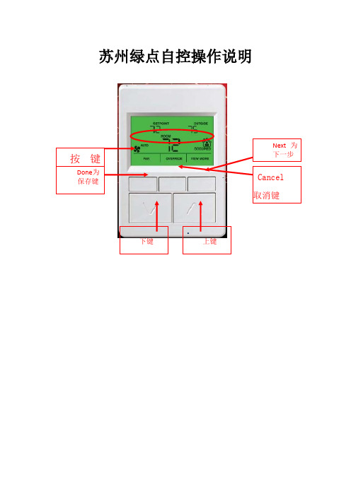
苏州绿点自控操作说明•面板对照表第一种类型UI1 MAU-201出风温度UI2 MAU-202出风温度UI5 MAU-201风车压差AO1 MAU-201冰水阀开度AO2 MAU-202冰水阀开度DI3 MAU-202风车压差Wsp_t1 MAU-201出风温度设定Wsp_t2 MAU-202出风温度设定Qh 冬夏切换第二种类型UI2 AHU-201回风温度UI3 2F末端水管压力AO1 AHU-201冰水阀开度AO2 AHU-201新风风门DI3 AHU-201风车压差DI4 AHU-201滤网压差Wsp_t1 AHU-201回风温度设定Qh 冬夏切换TR71面板操作说明面板显示点与接线表相对应例如:UI1:出风温度DI3:风车压差AO1:冰水阀开度AO1_DIS:冰水阀开度显示AO1_AM:与上述对应的手自动切换,“0”为自动,“1”为手动AO1_IN:与上述对应手动强制输入点Wsp_t1:出风温度设定值,可任意修改所需值以下为面板操作步骤:上述为主界面,按右边第一位,就可以进入显示屏上分3段,刚好底下有3个按键与此对应,从左到右依次为DONE,CANCEL,NEXT(确定,取消,下一步)按住NEXT,就可以看到这台控制器里面所有的点上述为UI1,继续点击NEXT,就能看到所有UI点对应的数据。
上述为DI1,显示风车的状态,故障和压差等,显示数值为“0”和“1”,“0”代表运行和正常,“1”代表停止与故障。
上述为阀体的开度显示点,AO1_DIS为蒸汽阀的开度显示上述为AO1冰水阀的手自动切换点,“0”代表蒸汽阀受程序自动控制,按照设计好的程序进行;“1”代表蒸汽阀不受程序控制,根据手动输入的值进行。
即“1”代表手动,“0”代表自动。
按面板上的上下键,就能修改数值。
上述为当AO1为手动强制输入之后的,AO1的强制输出值,通过上下键修改数值,之后按左上角的DONE键确认。
(0~100对应0~10V)上述为水泵和阀体的启停点,“0”代表停止,“1”代表启动。
Honeywell-XL50控制器操作说明资料讲解

Honeywell-XL50控制器操作说明1.可编程控制器和仪表可编程控制器XL20、XL50 (的核心元件,它在系统中起到重要作用:如检测各传感器的当前值,动态调整个比例阀的状态,显示系统各参数等;还提供了一些控制系统内部参数的调整和系统参数的设定方式,用户应对其操作方法和性能达到熟练的程度,才能实现空调系统的各种操作。
XL20为中文控制屏,不带通讯方式,操作方法雷同XL50。
取消键–返回先前的或上一级的屏幕;取消未被确认的操作;确认报警信息。
上移键–移动指针到前面的行下移键–移动指针到下一行右移键–移动指针到当前位置的右边左移键–移动指针到当前位置的左边增加键–每按一次增加数值一个单位或改变数字状态值到与当前状态值相反的状态值减少键–每按一次减少数值一个单位或改变数字状态值到与当前状态值相反的状态值确认键–确认已做的修改和进入下一个屏幕(指针在NEXT前)对于KTF空调系统的控制操作,主要是对系统参数的查看和更改(即对“系统参数操作键”的使用),该控制器的强大功能主要体现在:不但可以在线修改所有输入、输出点,而且也可以对控制系统的内部参数进行改变。
a)查看系统的输入、输出点状态(即查询新回风温度、露点温度、出口温湿度、风压及其各个阀门开度)♦ 重要说明:对DDC 控制器的操作只能单键进行,严禁同时按压键位,以避免不必要的误操作,以免程序被初始化或删除。
♦ 按下系统“参数”操作键,屏幕出现“请输入你的密码”;密码输入才可以修改数据,比如压力等参数的设定等。
用户只是查看的话就可以直接进入。
♦ 移动“光标移动”向上键,使光标停留在“****”上,再按下“输入键”,通过使用“数据增/减键”和“输入键”逐个将4位密码输入,完毕后屏幕左下角出现‘更改change ’字符;光标移动到change 字符上可以修改进入DDC 修改数据的密码,默认为‘3333’,如更改了密码,用户须牢记更改后的密码,每次参数修改操作都需密码。
霍尼韦尔XL50A-UMMIPCCBLON的详细说明

深圳市中航电脑智能系统有限公司霍尼韦尔XL50A-UMMIPCCBLON的详细说明霍尼韦尔XL50A-UMMIPCCBLON,XL50-MMI-FP,DDC控制器的详细说明是:XL50-MMI-FP可用于单独的不联网的就地控制,具有通讯功能,与Excel 5000系统集成在同一个网络上,它可代替Excel 20控制器,内含通讯模块,并可自由编程控制,Excel 50 有8个A1点,4个AO点,4个DI点和6个DO点。
Excel 50 带有结构化软件的HVAC控制器和可自由编程XL50A-UMMIPCCBLON适用于所有HVAC控制应用软件和楼宇自动化功能的EXCEL5000系统内的DDC控制器。
控制器可应用于独立运行,拨号和网络系统。
适用于中小型建筑物。
硬件输入信号* 传感器NTC20k, 0..10V, 0..20mA的8个输入信号* 无电势触点或24V的4个附加输入信号硬件输出信号* 4个模拟输出信号0..10V* 6个数字输出信号24Vac控制面板:同控制面板XI582AH相匹配的RS232端口。
本控制面板可用于调节设置点,警报限位,固定输入/输出信号,手动操作功能等(模块XL50-MMI已经安装了自己的控制面板) 管理应用软件:XBS或EBI系统可用做中央管理和其他楼宇的自动化功能。
独立运行:是安装:DIN导轨或配电柜前门防护等级:适用于安装在配电柜前门的带有XL50-ACC3的IP30, IP54接线柱类型:适用于XS50螺旋接线柱或XSP526/XSP534扁平电缆接线柱存储备份:用于72小时缓冲器的镀金电容器电源:24Vac | 10VA连接调制解调器:通过应用软件卡可直接连接连接通讯总线:通过应用软件卡可直接连接连接LonWorks(R):通过应用软件卡可直接连接附加说明:如果不需要可编程性,应用Honeywell的Lizard软件来为所需要的设备选者适当的控制软件。
需要提供46个网络变量以使所有设备在LonWorks(R)系统中协调运行基本配置:XL50-MMI-+ XD50-FCL+ XS50:带有LON通讯接口的XL50 XL50-MMI。
海伦威尔传感器和控制产品指南说明书
98109071For innovation that’s well apart, there’s only Honeywell Sensing andTable of ContentsMagnetoresistive Sensor ICs . . . . . . . . . . . . . . . . . . . . . . . . . . . . . . . .3 Hall-Effect Digital Sensor ICs . . . . . . . . . . . . . . . . . . . . . . . . . . . . . .4-5 Hall-Effect Digital and Linear Sensor ICs . . . . . . . . . . . . . . . . . . . . .6-7 Value-Added Hall-Effect Sensors . . . . . . . . . . . . . . . . . . . . . . . . . . . .8-9 Speed and Direction Sensors . . . . . . . . . . . . . . . . . . . . . . . . . . . .10-11 Linear Potentiometric Sensors . . . . . . . . . . . . . . . . . . . . . . . . . . . .12-13 SMART Position Sensors . . . . . . . . . . . . . . . . . . . . . . . . . . . . . . .14-15 Ultrasonic Sensors . . . . . . . . . . . . . . . . . . . . . . . . . . . . . . . . . . . .16-17Inertial Measurement Unit . . . . . . . . . . . . . . . . . . . . . . . . . . . . . . . . .18 Proximity Sensors . . . . . . . . . . . . . . . . . . . . . . . . . . . . . . . . . . . . .19-21 Encoders and Non-Contact Hall-Effect Sensors . . . . . . . . . . . . . . . .22 Cermet and Wirewound Potentiometers . . . . . . . . . . . . . . . . . . . . . .23 Conductive Plastic Potentiometers . . . . . . . . . . . . . . . . . . . . . . . .24-25 Resolvers . . . . . . . . . . . . . . . . . . . . . . . . . . . . . . . . . . . . . . . . . . . .26-27 Honeywell S&C Core Industry Segments . . . . . . . . . . . . . . . . . . .28-29 Honeywell S&C Product Portfolio . . . . . . . . . . . . . . . . . . . . . . . . .30-312 3With a built-in magnetoresistive bridge integrated on silicon and encapsulated in a plastic package, magnetoresistive sensor ICs feature an integrated circuit that responds to low fields at large distances. Potential applications include laptops, material handlingequipment, and pneumatic cylinders.Constructed from a thin sheet of conductive material, Hall-effect sensor ICs have output connections perpendicular to direction of current flow. Potential applications are many, including speed and RPM sensing, brushless dc motors, and fan/motor/robotics.Featureslow supply voltagecombined with very lowaverage current reducespower consumptionhigh output current andspeed capability; reversepolarity protectionbuilt-in pull-up resistor;low voltage; enhancedsensitivitysimple activation from aSouth pole and multiplemagnetic sensitivites (high,medium, and low)4 5-40 °C to 150 °C [-40 °F to 302 °F]-40 °C to 150 °C [-40 °F to 302 °F]-40 °C to 125 °C [-40 °F to 257 °F]-40 °C to 125 °C [-40 °F to 257 °F] -40 °C to 125 °C [-40 °F to 257 °F]V) & SS461R: 40 °C to 150 °C [-40 °F to 302 °F]; SS361RT (3 V to 18 V): -40 °C to 125 °C [-40 °F to -40 °C to 150 °C [-40 °F to 302 °F]-40 °C to 150 °C [-40 °F to 302 °F]simple activation from a North pole (SS345PT) or a South pole (SS445P)built-in reverse polarity protection; typical operating point of 85 G at 25 °C [77 °F]fastest response timein class; no chopperstabilizationtime in its class, nochopper stabilization,operates from only30 Gauss typical, at 25 °C [77 °F]enhanced sensitivity; built-in reverse voltage capability enhanced sensitivity; built-in reverse polarity protection; robust designmultiple operate/release points available high output current; reverse polarityprotectionConstructed from a thin sheet of conductive material, Hall-effect sensor ICs have output Array connections perpendicular to direction of current flow. Potential applications are many,including speed and RPM sensing, brushless dc motors, and fan/motor/robotics.6 7SS39ET/SS49E/SS59ET8 Consists of sensors packaged in a variety of housings. Includes vane sensors, digital position sensors, and solid-state switches. Potential applications include position and RPM sensing, cam and crankshaft speed and position, transmissions, tachometers, traction control, and sprocket speed.Featuresor sourcing output; aluminum housing; color-coded jacketed cable; adjustable mountingaluminum housing; color-coded jacketed cable;adjustable mounting9polarity and transient protection; EMIresistantsensing; environmentally sealed; three terminations and bipolar magnetics; sinking output; frequencies exceeding 100 HzNEMA 3, 3R, 3S, 4, 4X, 12 and 13; omnipolar magnetics; sinking outputProvides true zero speed capability, direction sensing, and precise switch pointmeasurement. Speed sensor diagnostics provide information on air gap and sensor failure for increased reliability and functionality. Potential applications include cam/crank shafts, transmissions, tachometers, traction control, dynamometers, process control, and factory automation.Featuresmultiple finger-wiper design; anodized extruded aluminum housing; precious metal contact; sealed constructioneter; multiple finger-wiper design; anodized extruded aluminumhousing; precious metal contact; sealed constructionvibration-dampened element; pre-cious metal wipers; stainless steelshaft; enhanced dc level output Includes potentiometer sensors for linear, rotary position, or displacement measurement with extended life PTFE bearings and precious metal multi-finger contact wipers. Potential applications include robotic control, marine steering, in-tank sensing, injection molding, and printing.precious metal wipers; 2,06 mm [0.081 in] thick housing with 6 mm [0.25 in] shaft; high level dc output; enhanced performance bearings; shaft seals design; stainless steel shaft; anodizedextruded aluminum housing; precious metalcontact; shaft seals for spray-or-hose-downenvironmentswiper design; stainless steel shaft; internalspring-loaded ball joint; anodized extrudedaluminum housing; precious metal contact;infinite resolutionvibration-dampened element; extendedside bearing; precious metal wipers; highdc level output; enhanced performance bear-ings; NEMA 4 sealingMeasurements75 mm: 145 mm L x 18,0 mm W x 28,2 mm H [5.7 in x 0.71 in x 1.1 in]225 mm: 287,3 mm L x 18,0 mm W x 28,2 mm H [11.3 in x 0.71 in x 1.1 in]Superior Measurement. Accurate. Reliable. Thinking.Honeywell’s SMART Position Sensors are some of the most durable and adaptable position devices available in the industry today. These sensors use a patentedcombination of ASIC (Application-Specific Integrated Circuit) technology and an array of MR (magnetoresistive) sensors to provide absolute position sensing with enhanced speed and accuracy. Their simple, non-contact design eliminates mechanical failure mechanisms, reduces wear and tear, improves reliability and durability, enhancesoperation efficiency and safety, and minimizes downtime. Linear configuration potential applications: valve position, material handling, plastic molding, wafer handling, CNC machines, passenger bus level position, truck-mounted crane outrigger position, heavy equipment attachment identification, engine transmissions (35 mm only), marine motors, and aircraft actuators.100°: 183 mm L x 86 mm W x 31 mm H [7.20 in x 3.39 in x 1.22 in]180°: 222 mm L x 107 mm W x 31 mm H [8.74 in x 4.21 in x 1.22 in]113,5 mm x 106,5 mm x 22,0 mm [4.46 in x 4.19 in x 0.87 in]Arc Configuration potential applications: aerial work lift platform, front end loader and digger/excavator boom position, scissor lift position, refuse truck lift and automatic reach arm position, mobile crane steering, timber harvester/processor equipment cutter arm angle, on-board loader weighing system position, telescoping conveyor elevation, power generation contact angle, rail-road crossing arms position, remote weapon systems elevation, chassis suspension systems positionheight, military vehicle door position, ground-based solar panels elevation and azimuth, ground-based satellite dish elevation and azimuth, robotically-assisted surgery equipment position, patient bed elevation.Rotary Configuration potential applications: steering angle, articulation angle, boom arm detection, solar panels,wind turbines.Ultrasonic sensors measure time delay between emitted and echo pulses. Available in analog or digital versions for distance or presence/absence sensing. Programmable versions available. May be used in a variety of rugged presence and absence sensing applications.Featureshead; synchronizing/hold input; adjustment by potentiometer; micro-processor controlled; temperature compensationteach in; M12 connector, 5 pin; visual indication; four output op-tions; synchronizing/hold input; temperature compensationface); four models; stainless steel M30 heads; synchronizing/hold input; beam power adjustable by switchremote teach-in/auto-tuning; Windows andhysteresis mode; two switching outputs;temperature compensation; connector orcable versioneight models; auto-tuning by one switch;slope direction selection; NO/NC selection;two switching outputs; analog output;temperature compensationIP65; auto-tuning by four position plug;switching output models; two switchingoutputs; temperature compensationIP67; four output configurations; switchingfrequency of 150 Hz; compact sizeFeaturesflexibility, application expertise, customization, and temperature performance; easesintegration; automotive-grade qualified, long term stability, no calibration neededInertial Measurement Units (IMU) are high-end position sensors with sensitive multi-axis motion control. These sensors measure the motion of the equipment onto which they are attached and deliver the data to the equipment’s control module, allowing the operator to focus on other equipment functions, enabling more precise control than can be achieved byusing only the human eye, thus increasing safety, stability and productivity.Designed to meet demanding temperature, vibration, shock, and EMI/EMP interference specifications. Multiple potential applications are found in aerospace, ordnance, marine, and off-shore equipment.Designed to meet demanding temperature, vibration, shock, and EMI/EMP interference specifications. Multiple potential applications are found in aerospace, ordnance, marine, and off-shore equipment.Featuresdetent feel; continuous electrical travelprinted circuit terms; outputs TTL compatibleMechanical versions with 2-bit and 4-bit gray code outputs for potential use in incremental and absolute electrical reference applications. Optical versions are manually operated, rotary devices. Available with PC terminals or cable leads. Potential applications include controls foraudio and lighting, level, cursor, frequency, temperature, time, and position sensing.Compact and rugged thick film devices, these potentiometers are stable over a rangeof operating temperatures. Provides high power dissipation and improved resistance temperature coefficient. Potential applications include joysticks, lighting, audio, telecom, manual, medical, and marine equipment, welding, and heating.Compact and rugged thick-film devices are available in wide range of resistance values. These devices use precision technology developed for military applications. Potential applications include manual controls, audio and lighting consoles, joysticks, telecommunication, and medical equipment.AerospaceAerospace applications are among the most demanding for any type of product. Rigorous FAA requirements, extreme environments (temperature, shock, vibration, the need forhermetic sealing), and the ability to customize devices are just a few of the parameters often required of sensors and switches in these applications. Aerospace customers typically value speed in prototyping and development, and Honeywell’s verticallyintegrated, AS9100-approved manufacturing locations enhance our ability to produce devices in a wide variety of packages. The precision output of our products helps reduce risk and cost in key applications while also minimizing the need for unscheduled maintenance.Honeywell’s in-depth aerospace engineering experience allows us to work with customers in the design and development ofHoneywell Sensing and Control is a global leader in providing reliable, cost-effective sensing and switching solutions for our customers’ applications. We serve thousands of customers in four core industry segments: industrial, medical equipment, transportation, and aerospace/military products.products that best meet the specified requirements of theirindividual applications. Making products simple to install makes the job easier every step of the way. And, the odds are that Honeywell is already on the list of trusted suppliers for many aerospace companies, underscoring the decades of experience we bring to this field.Honeywell products for this industry (many of them PMA-certified) include force sensors, load cells, potentiometers, pilot controls, pressure sensors, pressure switches, resolvers, sensor/actuator assemblies for systems ranging from aerostructures to fuel control to flight surfaces, speed sensors, temperature probes, thermostats, torque sensors, y-guides for cargosystems, MICRO SWITCH™ sealed and high-accuracy switches, MICRO SWITCH™ pushbutton switches, and MICRO SWITCH™ rocker and toggle switches.MedicalMedical applications typically require sensors and switchesthat are highly stable and extremely reliable to enhance patient safety and comfort. Stability is often essential to minimize long term drift, reduce the need for recalibration, and improve ease of use for medical equipment operators. Reliability enhances patient safety in life-critical applications, reduces downtime, and improves test throughput in applications such as clinical diagnostics. The product needs to be easy to use and easy to design into a system, so Honeywell’s extensive customization and built-in calibration/amplification capabilities are strong benefits. Confidence in Honeywell’s product performance, reliability, and availability provide peace of mind for medical equipment manufacturers who choose Honeywell.Honeywell offerings for this industry include airflow sensors, board mount and stainless steel media isolated pressure sensors, Hall-effect magnetic position sensors, humidity sensors, flexible heaters, force sensors, thermostats, commercial solid state sensors, infrared sensors, oxygen sensors, pressureand vacuum switches, potentiometers and encoders, MICRO SWITCH™ pushbutton, rocker, and toggle switches, and hour meters.IndustrialThe industrial arena can be a rough one. From high-speed food processing to high-force stamping applications, reliable and cost-effective sensors and switches often help minimize repair costs, maximize system life, and reduce overall system expense. Durability can mean the difference between smooth-running processes and expensive downtime. Accurate, repeatable sensor or switch output can reduce the need for calibration once the device is applied. Because of the wide variety of potential applications, Honeywell’s ability to deliver a customized product that can meet virtually any size, weight, and power requirement – as well as any packaging stipulations for tough, harsh environments – often makes it easy to incorporate and use our devices. Safety is another important consideration for industrial users, and our products meet a wide variety of regulatory safety requirements.Honeywell’s industrial product line includes airflow sensors, current sensors, humidity sensors, fiber-optic and liquid-level sensors, linear position sensors, oxygen sensors, pressure sensors, potentiometers and encoders, speed sensors, temperature probes, ultrasonic sensors, wirewound resistors, thermostats, commercial solid state sensors, flex heaters, SMART position sensors, board mount and stainless steel media isolated pressure sensors, force sensors, safety light curtains, push-pull switches, and MICRO SWITCH™ basic switches, hazardous area switches, safety switches, key and rotary switches, limit switches, sealed and high-accuracy switches, pushbutton, rocker, toggle switches, and relays. TransportationGetting from Point A to Point B is often challenging for end-customers of transportation providers – Honeywell aims to make the trip easier with highly reliable, cost-effective switches and sensors. Our products are designed to support rigorous engine requirements, and their efficiency can also help optimize engine performance. Customization is often required to allow a switch or sensor to be mounted in tight or challenging environments including vibration, temperature extremes, and road contamination. The durability of Honeywell products enhances system reliability, which is also boosted by the stable, accurate output of our devices. All of these capabilities allow demanding customers to rely on Honeywell’s many years of experience in the transportation industry.Honeywell products for transportation applications includeHall-effect rotary position sensors, inertial measurement units, infrared sensors, keyless entry sensors, magnetic position sensors, pressure sensors, speed and direction sensors, ultrasonic sensors, thermostats, temperature probes, commercial solid state sensors, SMART position sensors, andMICRO SWITCH™ pushbutton, rocker, and toggle switches.SENSORSThermostats: Commercial and precisionsnap-action. Automatic or manual reset options,phenolic or ceramic housings.May be used in: Telecommunications• Battery Heater Controls • Computers• Copy Machines • Fax Machines • FoodService • Food Carts • Small and MajorAppliances • Heat and Smoke Detectors• HVAC Equipmentapplications that involve measurementof hostile media in harsh environmentscompatible with 316 stainless steel.May be used in:Control SystemsCurrent sensors:Almost no thermal drift or offset with Flexible heaters:spiral wrap, transparent, composite and high temperature configurations with single, multiple and variable watt densities. Can be bonded parts or combined.May be used in:••Digital and analog Hall-effect position ICs, magnetoresistive position ICs, Hall-effect vane,Motor/Fan Control • Magnetic EncodingMotion Control/Detection • Power/Position30 Limitless ™ switches and receivers: Combines the best of MICRO SWITCH ™ limit switches with commercial wireless technology. Beneficial for remote monitoring where wiring/maintenance is not physically possible or economically feasible. Used for position sensing and presence/absence detection.Limitless ™ Operator Interface: Adds a human interface device to the product-driven interfaces of Limitless ™ switches and receivers. Choose and install a desired operator or utilize one of Honeywell’s pushbuttons.May be used in: Valve Position • Crane Boom/Jib/Skew Position • Lifts • Material Handling • Presses • Construction/Ag Machines • Conveyors • Industrial Environments • Remote/Temporary Equipment • Grain Diverters or Flaps • Door PositionLIMITLESS ™ WIRELESS SOLUTIONSand LSX Series.May be used in:Conveyors • Off-Shore Drilling • Waste-Treatment Plants • Paint Booths Handling FacilitiesPressure and vacuum switches:setpoints from 0.5 psi to 3000 psi. Rugged31SAFETY PRODUCTSMICRO SWITCH ™ safety switches: For operator point-of-operation protection, access detection, presence sensing, gate monitoring and electrical interfacing. High-quality, dependable, cost-effective solutions.May be used in: Packaging and Semi-Conductor Equipment • Plastic-Molding Machinery • Machine Tools • Textile Machines • Lifts • Industrial Doors • Bailers • Compactors • Aircraft Bridges • Telescopic Handlers • Refuse VehiclesHoneywell Sensing and Control1985 Douglas Drive NorthGolden Valley, MN 000709-18-EN IL50 GLO Printed in USA October 2013© 2013 Honeywell International Inc. All rights reserved.Find out moreTo learn more about Honeywell’s sensingand control products, call+1-815-235-6847, email inquiries to*********************, or visitWarranty/RemedyHoneywell warrants goods of its manufacture as being free of defective materials and faulty workmanship. Honeywell’s stan-dard product warranty applies unless agreed to otherwise by Honeywell in writing; please refer to your order acknowledge-ment or consult your local sales office for specific warranty details. If warranted goods are returned to Honeywell dur-ing the period of coverage, Honeywell will repair or replace, at its option, without charge those items it finds defective. The foregoing is buyer’s sole remedy and is in lieu of all other warranties, expressed or implied, including those of merchantability and fitness for a particular purpose. In no event shall Honeywell be liable for consequential, special, or indirect damages.While we provide application assistance personally, through our literature and the Honeywell web site, it is up to the cus-tomer to determine the suitability of the product in the applica-tion.Specifications may change without notice. The information we supply is believed to be accurate and reliable as of this print-ing. However, we assume no responsibility for its use.9810907。
Honeywell温控器详细说明书

HoneywellDC1000系列通用调节器简要说明书(中文版)注意:使用本手册前,请检查量程,输入,输出是否符合您的要求.1.面板说明1.1显示说明PV: 过程值(process value),四位显示(红色)SP: 设定值(set point),四位显示(绿色)1.2LED指示灯说明OUT1: 第一路输出(OUTPUT1), 绿色灯OUT2: 第二路输出(OUTPUT2), 绿色灯AT: 自整定,黄色灯PRO: 程序运行中,黄色灯AL1: 第一路报警(ALARM 1),红色灯AL2: 第二路报警(ALARM 1),红色灯AL3: 第三路报警(ALARM 1),红色灯 (DC1010无此功能)MAN: 手动控制,黄色灯 (DC1010无此功能)1.3 按键SET: 模式&设定键(切换模式和写入设定值)Y:移位键▽:减少键△:增加键A/M:自动/手动切换键2.自整定功能2.1 将AT设置为‘YES’,即启动自整定功能2.2 自整定完成后,PID参数将被自动设定。
(P值一般为11~14, I值一股为40~50, D值一般为40~60。
)2.3 ATVL=自整定偏移量,由SP值推导出来(它在自整定时,可防止振荡超过设定点)SP-ATVL=自整定设定值, ATVL=自整定偏移量例如: SP=200℃, ATL=5, 则自整定点是195℃*ATVL务必自整定点在程序类型模式中(195℃)2.4 自整定点失败2.4.1 ATVL值太大→如果不能确定,则设定ATVL=02.4.2系统时间太长→单独设定PID参数3. 故障信息(注意)当有“*”标记的故障发生时,控制器需要维修4.操作流程各阶层进出及参数的锁定4.1.1按移位键(Y)改变参数。
按下移位键,第一位数开始闪烁。
按增加键(△)或减少键(▽)对此数值作增加或减少,再按移位键到第二位数,当所有数值设定好后,按SET键完成数值设定。
4.1.2SET键也有转换模式的功能,按下SET键会显示下一种模式4.1.3按SET键持续5秒可进入LEVEL2,或同样可返回LEVEL1。
Honeywell 枪机使用手册
B
11/06
Honeywell
目录
1. 关于本手册 ....................................................................................................................................... 1 内容概览 ........................................................................................................................................... 1 特殊字体与符号 ................................................................................................................................ 1 注意事项与安全警告 ......................................................................................................................... 2 FCC 认证声明................................................................................................................................... 2 声明 .............................................................
HoneyWell 基本操作

参考答案系统操作1、HM的复位和启动HM的复位:1)进入系统状态画面将HM SHUTDOWN两次使HM处于FAIL状态.2)按节点电源上的复位(RESET)按钮。
HM的启动:1)打开节点卡件箱的交流电源。
2)打开HM节点电源。
3)由于HM具有自启动功能,因此,HM上电后可以自行启动。
4)等待一段时间,直到该HM的LCN地址显示正确后查看系统状态画面,若HM状态OK说明HM已启动完毕。
2、US的复位通过按US操作员键盘上的复位(RESET)按钮。
从HM启动一台US的方法1)打开US卡件箱的交流电源。
2)打开该US的节点电源,等待直到该节点的LCN地址显示正确。
3)按一下操作员键盘上的LOAD键,此时CRT上出现:“N,1,2,3,4,X?”询问启动文件从哪里存取?4)输入N后按ENTER键5)等待一会后CRT上出现“OPR,ENG,UNP,X?”询问该US装载何种属性?6)输入O(OPR)为操作员属性或E(ENG)为工程师属性或U(UNP)为万能属性,然后ENTER。
7)等待一段时间,直到操作台状态显示画面中相应的US状态为OK则该US启动完毕。
从快速启动盘启动一台US的方法1)打开US卡件箱的交流电源。
2)打开该US的节点电源,等待直到该节点的LCN地址显示正确。
3)将快速启动盘插入ZIP驱动器4)按一下操作员键盘上的LOAD键,此时CRT上出现:“N,1,2,3,4,X?”5)输入插有快速启动盘的ZIP驱动器号后按ENTER键6)等待一会后CRT上出现“OPR,ENG,UNP,X?”询问该US装载何种属性?7)输入O(OPR)为操作员属性或E(ENG)为工程师属性或U(UNP)为万能属性,然后ENTER。
8)等待一段时间,直到操作台状态显示画面中相应的US状态为OK则该US启动完毕。
从一台US上启动另一台US的方法1)按CONSOLE STATUS键进入控制台状态显示画面。
2)选择需启动的US节点确认该US节点处于POW ON状态。
精选HONEYWELL楼控调试手册
楼控调试手册目录目录 (3)1、BAS系统设备检测及调试步骤(STAM)概述 (1)A. 在实际调试工作开始之前准确的制定调试计划,并使用户能够了解我们的调试步骤 (1)B. 指导调试人员进行系统调试 (1)C. 按调试步骤制定及生成准确的调试记录和报告 (1)2、DDC 加电检测 (2)2.1 Excel 50加电检测步骤 (2)A:控制程序的编译: (2)B:控制器的设置 (3)C:程序下载 (4)2.2 Excel 100 加电检测步骤 (7)1) 在控制器逻辑模块安装之前完成底座安装和现场接线。
(7)2) 确保控制器屏蔽接地连接的完整性。
(7)A:控制程序的编译: (7)B:控制器的设置 (8)C:程序下载: (9)2.3 Excel 500 加电检测步骤 (12)1) 在控制器底座和现场接线过程中及控制器逻辑模块安装之前。
(12)A:控制程序的编译: (13)B:控制器的设置 (13)C:程序下载: (14)3. BA系统监控设备现场调试方案 (16)3.1空调机组的调试方案 (16)A. 送风风机启停及状态均为“关”。
(16)B. 冷热水控制阀关闭。
(16)C. 所有风阀处于“关闭”位置。
(16)D. 过滤器报警点状态为“正常”。
(16)E. 风机前后的压差开关为“关”。
(16)3.2、新风机组测试方案 (18)A) 送风风机启停及状态均为“关”。
(18)B) 冷热水控制阀关闭。
(18)C) 所有风阀处于“关闭”位置。
(18)D) 防冻开关的报警点状态是否为“正常”。
(18)E) 风机前后的压差开关为“关”。
(18)3.3 FCU末端的调试方案 (20)A. 送风风机启停及状态均为“关”。
(21)B. 冷热水控制阀关闭。
(21)3.4 送、排风机的调试方案 (22)A. 排风风机启停及状态均为“关”。
(22)B. 风机故障报警点为“正常”。
(22)3.5 给水系统调试方案 (22)C. 水泵启停及状态均为“关”。
霍尼韦尔安全操作指南
Honeywell PKS系统维护手册第一章日常维护第二章卡件更换第三章控制器第四章 I/O卡件第五章常见故障第六章 PID整定系统使用维护DCS系统是由系统软、硬件,操作台盘及现场仪表组成的。
系统中任一环节出现问题,均会导致系统部分功能失效或引发控制系统故障,严重时会导致生产停车。
因此,要把构成控制系统的所有设备看成一个整体,进行全面维护管理。
1.1日常维护1.1.1机柜室管理应加强机柜室人员和设备管理。
为保证系统运行在适当条件下,请遵守以下各项:1)密封所有可能引入灰尘、潮气和鼠害或其它有害昆虫的走线孔(坑)等;2)保证空调设备稳定运行,保证室温变化小于+5℃/h,避免由于温度、湿度急剧变化导致在系统设备上的凝露;3)现场与控制室合理隔离,避免现场灰尘进入控制室,同时控制室定时清扫,保持清洁。
4)进入机房、工程师室作业人员严格遵守各项规章制度,进出须换鞋或带鞋套,不得将污物、食品、饮料等带入机房;爱护机房、工程师室内设备,保持机房、工程师室整洁;进入机柜间应关闭手机。
5)过程控制计算机机柜间内禁止使用无线对讲设备。
6)技术组全面负责过程控制计算机的管理,各班组负责过程控制计算机机房、工程师室的日常卫生和日常维护工作。
工程师室内计算机及网络设备的维修由技术组成员负责,班组配合。
技术组成员在维修完设备后应做好设备规格化工作。
7)日光灯完好、灭火器按期检查、室内卫生整洁、操作台(柜)、主机外部、显示器、打印机等卫生清洁、打印机不缺纸、机柜内设备如机柜过滤网清洁、风扇完好,电话机、其他未明确但属于共有的设备等完好。
8)布线层的槽盒盖可以不盖,但应根据规格大小整洁地放置在地面上。
布线层墙壁、电缆进线口应密封,无人时,电灯只保留一组常亮。
9)室内施工管理:本班的设备施工作业由本班完成,外委作业时由本班派人监护(包括分析、检修等工作涉及更改电源时)。
施工结束后应做到工完料净场地清,负有管理责任的班组应及时向对方班组指出施工作业后的室内卫生等问题。
XL50说明书

空调自控系统说明书苏州达实控制设备有限公司2011.12 一:控制器说明:XCEL50控制器是Honeywell(霍尼韦尔)XBS 楼宇自动化系统中的现场DDC控制单元,是替代EXCEL20控制器的最新产品,可应用与于单独的AHU就地控制,它内含通讯模块可与EXCEL 5000系统集成在一个网路中,同时提供ISDN和LON总线的通信方式,EXCEL50控制器采用Flash EPROM模块可自由编程适用于Honeywell的CARE编程软件包,控制器可根据需要提供不同的现场预制程序。
1)硬件部分硬件结构8路通用传感器输入----- Analog input4 路无源数字量输入-----Digital input6 路数字点输出 -----Digital outputt4 路模拟点输出 ----- Analog outputI/O点特性:通用输入: NTC热敏电阻、PT1000温度传感器、0~10VDC信号、4~20mA 信号、干接点;数字输入:无源干接点、逻辑电平、记数脉冲;通用输出:模拟输出0~10VDC;数字输出:TRAIC输出;2):技术规范工作电压 24VAC工作频率 50/60HZ输入分辨率 0.1K/1MA电压调节信号 0~10V查询速度和刷新时间 1s继电器触点电压 24~220VAC触点最大负载 4A二:控制原理:1):温度控制在使用时根据实际,选择冷热模式.夏季,由回风温度控制冷水阀,即当回风温度高于除湿设定值时开大冷水阀,冷水流量增加,制冷能力增加,当回风温度低于设定值时关小冷水阀,冷水流量减少, 制冷能力减少。
在冬季,由回风温度控制热水阀,即当回风温度低于加热设定值时打开热水阀.2):室内静压控制根据室内的静压控制新风阀和回风阀的开度.3):联锁控制1.空调系统与风机联锁, 当风机启动时, 控制系统正式启动,各个控制元件开始控制过程;2.风机与冷热水阀、电加热器、加湿器的联锁控制,当送风机停机时,相应设备全部关闭三:操作说明:1、基础操作键:“取消键”,退出上级菜单或取消已修改的参数或退出报警确认;“上行键”,移动光标至上一行;“下行键”,移动光标至下一行;“右行键”,移动光标至下一个参数栏;“左行键”,移动光标至上一个参数栏;“增加键”,增加一个修改的单位或切换数字量的一个状态;“减少键”,减少一个修改的单位或切换数字量的一个状态;“确认键”,确认已修改的参数或移动光标至下一个界面2、功能操作键:“PLANT键”,显示该现场DDC控制器的相关状态;“TIME 键”,显示该现场DDC控制器的时间控制程序;如:控制器当前时间、TIMESCHEDUL时间表等,该功能在本系统未使用“参数键”,显示该现场DDC控制器的所有数据、控制点的状态、设定点、DDC参数表等;“报警键”,显示该现场DDC控制器的所有报警状态、报警历史、已处于ALARM的数据点;3、高级操作:3.1通电后,按,出现如下菜单3.2按菜单键,首先进入密码菜单后,先按键,进入以下菜单:进入密码3333,按键进入以下菜单按键可选择进入相应选项,按键确认。
Honeywell操作手册

Honeywell
一览
管理文件 对公司外保密
项目 到货确认 装箱确认
2016/05/10
2/5操作手册1.到货认(1)到货确认店铺
2
直接点击或者按数字键3,进入到 货确认模块
Honeywell
1
用触控笔双击桌面的【LPPDAV4的 快捷方式图标】
3
输入文件名,按【ENT】键回车
4
扫描箱号,数量默认为1。连续
操作手册
店铺
Honeywell操作手册
Honeywell操作手册 一览
NO.
Honeywell操作
Honeywell
一览
管理文件 对公司外保密
项目
Honeywell操作手册
2016/05/10
1/5
操作手册
店铺
Honeywell操作手册
Honeywell操作手册一览
NO. Honeywell操作手册-1 Honeywell操作手册-2
2016/05/10
4/5
操作手册
2.装箱确认
(2)装箱确认
5
扫描条码 (备注1)
店铺
Honeywell
6
该箱内的条码全部扫描完毕后, 输入0后按【ENT】回车键返回扫 描箱号界面
7
重复5、6步骤,直至所有箱内明细 扫描完成。扫描完成后,输入0按 【ENT】回车键
8
返回盘点程序主界面,单击红色 【X】返回盘点枪桌面
2016/05/10
5/5
扫描箱号直至箱号扫描完成
5
所有箱子扫描完毕后,输入88,
按【ENT】回车键退出
2016/05/10
3/5
操作手册
2.装箱确认
DDC操作手册 自动控制系统操作手册

自动控制系统操作手冊亚司艾国际贸易有限公司!HoneywellXL20操作說明(一) XL20控制器面板基本按鍵功能1. 跳出本項目與回到上一頁。
2. 進入控制器時間系統。
3. 進入控制器主要設定目錄。
4. 列出警報點。
5. 、、、改變游標位置。
6. 、改變設定值。
7. 確認與輸入。
(二) XL20控制器於送電後必須設定控制器時間,其方法如下:1. 連續按使面板螢幕顯示如下:SCH1mon/Data/Year下頁2. 按鍵使面板螢幕顯示如下:系統時間- - - - - -下頁3. 將游標移動至「系統時間」後按,面板螢幕即顯示如下:- - - - - -日期時間下頁4. 將游標移動至「日期時間」後按,面板螢幕即顯示如下:日期:mon/Day/Year時間:HR/mm下頁5. 將游標移動至日期的月、日、年或時間的小時、分鐘,後按 加以 、 移動游標,即可由 或 改變新的數值,更改結束後按 即可。
(三) XL20控制器主要功能設定:1. 連續按 使面板螢幕退出首頁:2. 按 使面板螢幕顯示如下:3. 若需更動內設之參數,須將游標移至password 處,再連續按兩次,其面板螢幕顯示如下:sch1mon/Day/Year下頁password下頁****password下頁4. 將游標置於 後,按 ,面板螢幕即顯示如下:类比输入:模拟量输入信号。
AHU***室内温度——室内温度传感器感测温度数值AHU***室内湿度——室内温度传感器感测湿度数值类比输出:模拟量输出信号。
AHU***加湿器——该台空调加湿器开度指令AHU***冷水阀——该台空调冰水阀开度指令AHU***热水阀——该台空调热水阀开度指令数位输入:开关量输入信号。
AHU***风机压差——该台空调运行状态AHU***加湿液位——该台空调加湿水盘液位状态下頁 类比输入 类比输出 下頁AHU***滤网检测——该台空调滤网状态AHU***烟感检测——该台空调火警状态数位输出:开关量输出信号。
霍尼韦尔安全操作指南(DOC49页)
Honeywell PKS系统维护手册第一章日常维护第二章卡件更换第三章控制器第四章I/O卡件第五章常见故障第六章PID整定系统使用维护DCS系统是由系统软、硬件,操作台盘及现场仪表组成的。
系统中任一环节出现问题,均会导致系统部分功能失效或引发控制系统故障,严重时会导致生产停车。
因此,要把构成控制系统的所有设备看成一个整体,进行全面维护管理。
1.1日常维护1.1.1机柜室管理应加强机柜室人员和设备管理。
为保证系统运行在适当条件下,请遵守以下各项:1)密封所有可能引入灰尘、潮气和鼠害或其它有害昆虫的走线孔(坑)等;2)保证空调设备稳定运行,保证室温变化小于+5℃/h,避免由于温度、湿度急剧变化导致在系统设备上的凝露;3)现场与控制室合理隔离,避免现场灰尘进入控制室,同时控制室定时清扫,保持清洁。
4)进入机房、工程师室作业人员严格遵守各项规章制度,进出须换鞋或带鞋套,不得将污物、食品、饮料等带入机房;爱护机房、工程师室内设备,保持机房、工程师室整洁;进入机柜间应关闭手机。
5)过程控制计算机机柜间内禁止使用无线对讲设备。
6)技术组全面负责过程控制计算机的管理,各班组负责过程控制计算机机房、工程师室的日常卫生和日常维护工作。
工程师室内计算机及网络设备的维修由技术组成员负责,班组配合。
技术组成员在维修完设备后应做好设备规格化工作。
7)日光灯完好、灭火器按期检查、室内卫生整洁、操作台(柜)、主机外部、显示器、打印机等卫生清洁、打印机不缺纸、机柜内设备如机柜过滤网清洁、风扇完好,机、其他未明确但属于共有的设备等完好。
8)布线层的槽盒盖可以不盖,但应根据规格大小整洁地放置在地面上。
布线层墙壁、电缆进线口应密封,无人时,电灯只保留一组常亮。
9)室内施工管理:本班的设备施工作业由本班完成,外委作业时由本班派人监护(包括分析、检修等工作涉及更改电源时)。
施工结束后应做到工完料净场地清,负有管理责任的班组应及时向对方班组指出施工作业后的室内卫生等问题。
贝加莱50点壁厚控制器说明书3.30

PP41型壁厚控制器使用说明书贝加莱工业自动化()目录系统特性简介 (3)1系统特性介绍 (3)2控制系统各部件介绍 (4)2.1控制操作面板 (4)2.1.1 面板42.1.2 接口52.1.3 性能62.1.4 安装62.2功能按键及指示灯 (7)2.3控制器及接线 (9)2.3.1AI351 (9)2.3.2 Am351 (10)2.3.3 PP41自带输入 (10)2.3.4 PP41自带输出 (11)3画面操作说明 (12)3.1登陆画面 (12)3.2连续式型胚曲线设定画面 (12)3.2.1 操作按钮 (12)3.2.2 输入参数 (13)3.2.3 输出参数 (14)3.2.4 插入与删除设定数值点 (14)3.2.5 微调设定数值点间的曲线单元 (15)3.3储料式型胚曲线设定画面 (17)3.3.1 操作按钮 (17)3.3.2 输入参数 (18)3.3.3 输出参数 (19)3.4曲线跟踪画面 (19)3.5标记画面 (20)3.6存储画面 (20)3.7文件改名画面 (21)3.8参数存储画面 (21)3.9文件调出画面 (22)3.10监控画面 (22)3.11数据1(曲线点)画面 (22)3.12数据2画面 (23)3.13初始设定画面 (23)3.13.1 输入参数 (23)3.13.2 模式转换 (24)3.14型芯设定画面 (24)3.14.1 输入参数 (24)3.14.2 输出参数 (25)3.14.3 手动调校 (25)3.14.4 自动调校 (25)3.14.5 调校提示: (25)3.15储料设定画面 (26)3.15.1 输出参数 (26)3.15.2 手动调校 (26)3.16增益设定画面 (26)3.16.1 按钮 (27)3.16.2 输入参数 (27)3.16.3 输出参数 (27)3.17时间设定画面 (27)3.17.1 输入参数 (27)3.17.2 输出参数 (27)3.18中英文切换画面 (28)4机器操作说明 (29)4.1开机步骤 (29)4.2系统参数设定 (29)4.2.1 初始设定 (29)4.2.2 型芯设定 (29)4.2.3 储料设定 (29)5故障处理 (30)5.1故障对应 (30)5.2干扰处理 (30)6电源 (30)7附件 (30)系统特性简介1系统特性介绍这是一款50点型坯壁厚控制器,用来控制中空成型机型坯的壁厚。
- 1、下载文档前请自行甄别文档内容的完整性,平台不提供额外的编辑、内容补充、找答案等附加服务。
- 2、"仅部分预览"的文档,不可在线预览部分如存在完整性等问题,可反馈申请退款(可完整预览的文档不适用该条件!)。
- 3、如文档侵犯您的权益,请联系客服反馈,我们会尽快为您处理(人工客服工作时间:9:00-18:30)。
Honeywell-XL50控制器操作说明
1.可编程控制器和仪表
可编程控制器
XL20、XL50 (霍尼韦尔)可编程控制器是实现本系统控制策略的硬件构成,是控制系统的核心元件,它在系统中起到重要作用:如检测各传感器的当前值,动态调整个比例阀的状态,显示系统各参数等;还提供了一些控制系统内部参数的调整和系统参数的设定方式,用户应对其操作方法和性能达到熟练的程度,才能实现空调系统的各种操作。
XL20为中文控制屏,不带通讯方式,操作方法雷同XL50。
取消键–返回先前的或上一级的屏幕;取消未被确认的操作;确认报警信息。
上移键–移动指针到前面的行
下移键–移动指针到下一行
右移键–移动指针到当前位置的右边
左移键–移动指针到当前位置的左边
增加键 – 每按一次增加数值一个单位或改变数字状态值到与当前状态值相反的状态值
减少键– 每按一次减少数值一个单位或改变数字状态值到与当前状态值相反的状态值
确认键 – 确认已做的修改和进入下一个屏幕(指针在NEXT 前)
对于KTF 空调系统的控制操作,主要是对系统参数的查看和更改(即对“系统参数操作键”的使用),该控制器的强大功能主要体现在:不但可以在线修改所有输入、输出点,而且也可以对控制系统的内部参数进行改变。
a) 查看系统的输入、输出点状态(即查询新回风温度、露点温度、出口温湿度、风压及其
各个阀门开度)
重要说明:对DDC 控制器的操作只能单键进行,严禁同时按压键位,以避免不必要的误操作,以免程序被初始化或删除。
按下系统“参数”操作键,屏幕出现“请输入你的密码”;密码输入才可以修改数据,比如压力等参数的设定等。
用户只是查看的话就可以直接进入。
移动“光标移动”向上键,使光标停留在“****”上,再按下“输入键”,通过使用“数据增/减键”和“输入键”逐个将4位密码输入,完毕后屏幕左下角出现‘更改change ’字符;光标移动到change 字符上可以修改进入DDC 修改数据的密码,默认为‘3333’,如更改了密码,用户须牢记更改后的密码,每次参数修改操作都需密码。
供应商无法破解密码,只能重新写入程序,如果不是要更改密码就从‘next ’字符进入。
下页next 按下屏幕将依次出现:模拟输入Analog input 、模拟输出Analog output 、逻辑输入Digital input ,右下角为next ,逻辑输出Digial output ,从下页next 处进入下一屏,上页back 为回到上一屏。
前面所列出的几项为物理输入输出点,信号输入、控制输出都是通过物理点来实现的,所以要查询工艺参数或阀门状态都在这里,在这不一一列举,附件会对每个点进行说明。
伪点(假设模拟点)Pseudo Analog ,蹦数位(假设Please enter your passward
****
Please enter your passward
****
逻辑点)Pseudo Digital 。
下图中带色标的栏在没有输入密码的情况将不会看到。
如果查询系统各点温湿度、风压等值,请进入“模拟输入”,如果查询各个阀门状态,则进入“模拟输出”(即移动光标,使之停留在相应位置并按下“输入键”);在进入相应界面后,屏幕将出现系统的各个输入/输出点名称,如果用户想查看其中一个,只须将光标移动在响应位置并按下“确认键”即可查看。
具体位置在附件中有标注。
参数设定在‘Mnual Operat ’,如果在‘Pseudo Analog ’中把需要修改的参数改成手动模式,在‘Mnual Operat ’都应该可以找到,这也避免对其它参数进行误操作。
内部PID 参数的修改在变数‘Parameters ’中修改,具体位置在附件中有标注。
注意除专业工程师外不可随意改变变数中参数。
b) 空调工艺参数命名,内部数据的修改(主要是设定、变数的修改) Analog input Analog output Digital input Digial output Totalizer Hours Run M-Bus Data Pseudo Analog Pseudo Digital Remote Analog Remote Digital Mnual Operat
Points in Trend Parameters System Data
M-bus Config DDC-Times Buswide Access
Trend Buffer Fiash EPROM
1PE1 2HE1 3TE1 1PE1
843
1-3TV1 2TV1 3HV1
1PSV1 L ist : 0
工艺参数的命名:P 表示压力、H 表示湿度、T 表示温度;E 表示输入、V 表示输出、SV 表示设定;如PE 表示为风压输入,TE 表示为温度输入;TV 表示温度控制的输出,HV 表示湿度控制的输出;PSV 表示压力的设定,TSV 表示温度的设定。
也有用拼音的头一个字母合在一起的作参数名称的,望请注意附件说明。
前面数字给参数定位,后面的数字表示不同的控制器位置,如1PE2表示在第2个控制器(DDC )里的压力参数。
参数在展开后如上图2,如果是需要修改并设定(物理点一定要自动,不可无故改成手动)就把光标移到‘自动AUTO ’字符上按确认,等到光标闪动的时候通过上下移动键改变状态到‘手动MANU ’并确定,这时会显示一个文本记录,在报警记录里可以查到的,按‘取消键C ’回到前一个界面,再移动到中间数字上设定想要的参数,如果状态已经改成手动就可以直接修改。
如果在任何界面上想退出,可按下‘取消键C ’(退出到上层)。
变数的修改举例如图5所示界面,List :0 代表的是变数表里的M0列表,变数表附件里只罗列了含风压温度湿度PID 参数的位置,其它不可随意调整,Number :3 中表示M0第三个参数,意思为风压控制PID 的P 值,具体位置见附件。
注意运行中修改数据幅度一定要小,避免带来大的波动。
默认参数是工程师的经验值,一般不用动。
DDC 重启操作规程
DDC 断电,通电重启显示画面如下: ①
显示为DDC 版本号,选择“NEXT ”进入下一页。
② Firmware version
V 2.06.10
NEXT
Date: No: 4
NEXT
第二页显示为年、月、日,时间和地址号,选者择“NEXT ”进入下一页。
③
第三页显示为通信卡内的内存容量,选者择“NEXT ”进入下一页。
④
第四页显示为程序的读取选项,选择“SELECT APPLIC ”进入下一页 ⑤
第五页显示为所要选取的程序,如选择“K1”进入下一页 ⑥
第六页显示为版本号,选择“NEXT ”进入下一页 ⑦
第七页显示程序已添加到DDC 内,选择“NEXT ”进入下一页 ⑧
第八页显示DDC初始页面,按□菜单键进入程序。
