高升压比的耦合电感的介绍
耦合电感作用范文

耦合电感作用范文耦合电感是指两个或多个线圈之间通过磁场相互作用而产生的电感现象,常用于电子电路中的信号传递、能量传输和滤波等应用中。
它在通信系统、功率放大器、滤波器等电路中起着重要的作用。
本文将从耦合电感的基本原理、种类和应用等方面进行阐述,以期更加深入地了解该现象。
首先,我们需要了解耦合电感的基本原理。
耦合电感是通过两个或多个线圈之间的磁场相互作用来产生的。
当一个线圈中有电流通过时,它将在周围产生一个磁场。
这个磁场可以穿透到附近的线圈中,从而在另一个线圈中产生感应电流。
这种通过磁场相互作用产生的感应电流称为互感。
然后,我们来看一些常见的耦合电感种类。
根据线圈之间的相对位置,可以将耦合电感分为磁性耦合和电容耦合两种。
磁性耦合是指两个线圈通过磁场相互作用而产生耦合电感。
这种耦合方式常用于变压器和互感器等应用中。
在变压器中,主线圈产生一个磁场,而且这个磁场穿透到另一个线圈中,从而在另一个线圈中产生感应电流。
通过变压器的磁性耦合,可以将输入端的电压变换为输出端的电压,从而实现电压的升降变换。
在互感器中,两个线圈的磁性耦合产生的互感电流可以用来测量电流或电压。
电容耦合是指通过电容器将两个线圈相互连接起来,从而产生耦合电感。
这种耦合方式常用于滤波器和振荡器等应用中。
在滤波器中,通过调节电容器的值可以改变两个线圈之间的耦合程度,从而实现不同频率的信号的滤波。
在振荡器中,通过调节电容器和线圈的参数可以实现不同频率的振荡信号的产生。
最后,我们来看一些耦合电感的应用。
耦合电感在通信系统中常用于信号的传输和接收。
在调谐电路中,通过调节耦合电感的参数可以实现对不同频率信号的有效接收和滤波。
在功率放大器中,通过耦合电感可以实现信号的放大和输出。
在无线电发射器中,通过耦合电感可以将电源输出的能量传输到天线中,从而实现信号的辐射。
此外,耦合电感还可以用于隔离不同电路之间的干扰,从而提高系统的可靠性和稳定性。
总之,耦合电感是一种通过两个或多个线圈之间的磁场相互作用而产生的电感现象。
电路分析基础第6章-耦合电感和理想变压器课件.ppt

uL1
d 11
dt
L1
di1 dt
uL2
d 22
dt
L2
di2 dt
(6.1-10)
第6章 耦合电感和理想变压器 图6.1-3 耦合电感的自感电压和互感电压
第6章 耦合电感和理想变压器
由互感磁链产生的感应电压称为互感电压。若互感电压
的极性与互感磁链的方向按右手螺旋定则选取(见图6.1-3(a)), 则线圈1和线圈2的互感电压分别为
第6章 耦合电感和理想变压器
在图6.1-2中,线圈1通电流i1,由i1所产生的并与线圈1 相交链的磁通Φ11称为线圈1的自感磁通,磁通Φ11的方向与 电流i1的参考方向符合右手螺旋定则。自感磁通Φ11与线圈1 的匝数N1的乘积为线圈1的自感磁链,即ψ11=N1Φ11。自 感磁链ψ11与电流i1的关系如下:
第6章 耦合电感和理想变压器 图6.2-8 例6.2-5用图
第6章 耦合电感和理想变压器
6.3 空 芯 变 压 器
空芯变压器通常由两个具有磁耦合的线圈绕在非铁磁材 料制成的空芯骨架上构成。它在高频电路和测量仪器中获得 广泛应用。由于变压器是利用电磁感应原理制作的,因此可 以用耦合电感来构成它的模型。图6.3-1(a)所示为空芯变压 器的电路模型。
di1 dt
(6.1-12)
根据右手螺旋定则,可标出电流所产生的磁通方向如图
6.1-3(b)所示。取感应电压极性与产生它的磁通方向符合右 手螺旋关系,则耦合电感的伏安关系为
u1
uL1
uM1
L1
di1 dt
M
di2 dt
u2
uL2
uM 2
L2
di2 dt
M
di1 dt
压力传感器力电耦合效应

压力传感器力电耦合效应
压力传感器是一种常见的传感器,用于测量物体受到的压力大小。
它通过将物体施力传递到传感器上,产生电信号输出。
然而,压力传
感器在使用过程中,会出现力电耦合效应,这种效应会对测量结果产
生影响。
1. 什么是压力传感器力电耦合效应?
压力传感器力电耦合效应指的是,在测压的过程中,受到的机械力会
导致传感器输出的电信号发生变化。
这种变化可能会引起信噪比的变化,进而影响对压力测量值的准确性。
2. 导致力电耦合效应的原因是什么?
(1)材料的热膨胀系数不同。
(2)由于材料之间的接触面积有限,传感器在接受机械压力时会产生
变形,而变形过程中会导致材料内部离子的运动,进而引发电磁干扰。
(3)传感器的电路设计不合理,可能会引起传感器内部干扰。
3. 如何避免力电耦合效应?
(1)选择合适的材料,使其热膨胀系数尽可能一致,减少温度引起的
变形,避免因材料而造成的传感器误差。
(2)适当增大连接面积,使电极更加牢固,减少机械变形对产生的干扰。
(3)采用抗干扰技术,如隔离技术、滤波技术等,减少传感器内部干扰,提高信噪比。
(4)加装抗干扰元件,如屏蔽罩、抑制器等,阻挡外界干扰信号,提
高测量精度。
4. 结论
压力传感器力电耦合效应是影响压力测量结果准确性的一种因素,需
要引起足够的重视。
避免力电耦合效应的方法主要包括合理材料选择、增大连接面积、采用抗干扰技术、加装抗干扰元件等。
只有选用正确
的技术手段,才能够保证压力传感器准确地完成压力测量任务。
耦合电感的计算

04
耦合电感计算实例分析
实例一:简单耦合电感电路计算
电路描述:包含两个互感线圈
的简单耦合电感电路,其中一
个线圈接有交流电源。
01
计算步骤
02
根据电路图,列出KVL方程。
03
利用互感系数和自感系数,将
KVL方程转化为关于电流的线
性方程组。
04
解线性方程组,得到各支路电 流。
05
注意事项:在列写KVL方程时
智能化设计工具
新型材料应用
基于人工智能和机器学习的设计工具可能 会在未来得到广泛应用,它们能够自动进 行耦合电感计算并给出优化建议。
新型磁性材料的应用可能会改变耦合电感 的计算方法和设计思路,为电路设计带来 新的可能性。
THANK YOU
感谢观看
实例三:含源耦合电感电路计算
解线性方程组,得到各支路电流和电 压。
注意事项:在处理含源耦合电感电路 时,需要注意电源的处理方式,以及 电路中各元件参数对计算结果的影响 。同时,还需要注意方程的求解方法 和计算精度等问题。
05
耦合电感实验设计与操作
实验目的与要求
掌握耦合电感的基本 概念和计算方法
耦合电感电路模型
耦合电感电路模型是用于描述和分析耦合电感电路的数学模型。在电路分析中,通常采用等效电路的 方法来简化分析过程。
对于耦合电感电路,可以将其等效为包含自感和互感的电路模型。其中,自感表示线圈自身的电感效 应,而互感则表示线圈之间的磁耦合效应。通过求解等效电路的电压、电流等参数,可以进一步分析 耦合电感电路的性能和特点。
02
耦合电感电路分析方法
互感电压与电流关系
互感电压与电流成正比
在耦合电感电路中,当一个线圈中的电流发生变化时,会在另一个线圈中产生感应电动势,该感应电动势与线圈 中的电流成正比。
耦合电感的原理及应用

耦合电感的原理及应用1. 耦合电感的基本原理耦合电感是指在电路中同时存在两个或多个彼此关联的电感元件。
耦合电感可以通过互感耦合将电能从一个电路传递到另一个电路。
其基本原理是通过磁场的相互作用,使得电路中的电流或电压发生相互影响。
1.1 自感耦合自感耦合是指一条线圈中的感应电流影响该线圈中的自感。
自感耦合常常用于电感电压倍增电路和滤波电路中。
自感耦合的原理如下: - 当电流在一个线圈中变化时,会产生磁场。
- 这个磁场进一步作用于该线圈,导致线圈中的感应电动势发生变化。
- 这个感应电动势会产生另一个电流,影响该线圈中的自感。
1.2 互感耦合互感耦合是指两个或多个线圈之间的磁场相互作用,从而影响彼此中的感应电动势和电流。
互感耦合常常用于变压器和电感耦合放大器等电路中。
互感耦合的原理如下: - 当电流在一个线圈中变化时,会产生磁场。
- 这个磁场进一步作用于另一个线圈,导致另一个线圈中的感应电动势发生变化。
- 这个感应电动势会产生电流,影响另一个线圈中的感应电动势。
2. 耦合电感的应用耦合电感在电路中有广泛的应用。
以下是耦合电感的几个常见应用:2.1 传输电能耦合电感在无线能量传输中起到关键作用。
将能量从一个电路传输到另一个电路,可以通过互感耦合电路来实现。
这在无线充电和无线通信系统中非常常见。
2.2 信号传输耦合电感还可以在信号传输中起到重要作用。
例如,音频放大器中的变压器耦合放大器,可以将低电压信号放大到足够的水平,以驱动扬声器或音响系统。
2.3 滤波电路耦合电感在滤波电路中也经常被使用。
滤波电路可以通过自感耦合实现针对某一频率范围的信号的滤波效果。
这对于消除噪声或选择特定频率信号非常有用。
2.4 电感电压倍增耦合电感可以用于电感电压倍增电路。
在这种电路中,通过自感耦合将输入电感的电压倍增,在输出端获得更高的电压。
3. 小结耦合电感是电路中广泛应用的元件之一,它通过磁场的相互作用实现将电能从一个电路传递到另一个电路。
电感 耦合

电感耦合一、电感耦合的基本原理电感耦合是一种基于电磁感应原理的电能传输方式。
当两个线圈靠得足够近,并且其中一个线圈中通有变化的电流时,会在另一个线圈中产生感应电动势。
这个过程就是电感耦合。
在电感耦合中,能量的传递是通过磁场进行的,而不是通过线路连接直接传输的。
电感耦合的基本原理可以用法拉第电磁感应定律来描述。
当穿过闭合导体回路的磁场发生变化时,就会在导体回路中产生感应电流。
同样地,当一个导体回路中的电流发生变化时,也会在附近的导体回路中产生感应电动势。
这个感应电动势的大小与穿过导体回路的磁通量变化率成正比。
二、电感耦合的特点1.高效节能:电感耦合可以实现高效的电能传输,减少了线路的能量损失。
由于没有直接的物理连接,电感耦合还可以避免由于接触不良引起的能量损失。
2.无线传输:由于电感耦合不需要直接的线路连接,因此可以实现无线传输。
这在许多领域都有着广泛的应用,如无线充电、无线传感器网络等。
3.电磁干扰:电感耦合会产生一定的电磁辐射,可能会对周围的环境和设备产生干扰。
因此,在某些应用中需要进行电磁屏蔽和噪声抑制。
4.传输距离有限:电感耦合的传输距离相对较短,一般在几厘米到几米之间。
这是因为磁场随着距离的增加而衰减,导致能量传输效率降低。
5.方向性:电感耦合具有方向性,即只能实现特定方向的电能传输。
因此,在某些应用中可能需要定向天线或者定向传输结构来实现可靠的电能传输。
三、电感耦合的应用1.无线充电:电感耦合在无线充电领域有着广泛的应用。
通过在充电器和设备之间放置相应的线圈,可以实现设备的无线充电。
这种技术已经被广泛应用于手机、智能手表等设备的充电中。
2.传感器网络:电感耦合在无线传感器网络中也得到了应用。
传感器节点之间可以通过电感耦合进行能量的传输和数据的交换,从而实现传感器网络的自组织和自供电。
3.磁力继电器:磁力继电器是一种利用电感耦合原理实现开关控制的装置。
当输入电流变化时,磁力继电器会产生感应电动势,使开关触点闭合或断开。
升压电感工作原理

升压电感工作原理升压电感是一种在电路中起到升压作用的电器元件,也被称为“电感升压器”或“升压变压器”。
它的工作原理是通过利用电感感应作用使得电压升高,从而达到升压的效果。
本文将详细介绍升压电感的工作原理及其相关知识。
一、升压电感的基本结构升压电感的基本结构由磁芯、线圈和固定支架组成。
其中,磁芯是电感的核心部分,起到了固定线圈和增强强磁场的作用。
线圈则是电感中的主体部分,由导线绕成,其一端与电源连接,另一端则产生升压的输出信号。
固定支架则起到固定总体结构的作用。
二、升压电感的工作原理升压电感的工作原理是通过电磁感应法则,利用线圈中的感应电场和磁场相互作用来实现电压升高的效果。
当电源施加电压时,电流会经过线圈,形成一个电磁场,进而感应出更高的电压。
在稳定的工作状态下,电磁场和电压可以达到一种平衡状态,使得输出的电压保持在一个稳定的值。
三、升压电感的主要特点升压电感的最主要特点就是能够实现电压的升高作用,多用于电源电路或某些特定场合。
此外,升压电感还具有以下几个重要的特点:1. 额定电流大:升压电感的设计时通常会加大线圈的截面积,因此其承受的电流也比较大。
2. 磁环的截面积要大:升压电感的磁芯通常采用沉淀的铁粉,其截面积要比其他电感大一些。
3. 工作频率范围较宽:升压电感常常需要在各种不同的工作频率下工作,因此其设计应该符合不同频率范围的工作。
4. 阻抗高:升压电感经常在直流或者低频下使用,所以阻抗较高,输出的电流也比较小。
5. 较小的体积:与传统变压器相比,升压电感具有相对较小的体积,更易于集成到微型电路中。
四、升压电感的分类升压电感通常可以分为三种类型:气芯式升压电感、磁芯式升压电感和变压器式升压电感。
1. 气芯式升压电感,通常是由铜丝制成的线圈,在中心没有任何的磁芯存在,因此称之为气芯式。
此种电感常常用于特定的高压和高频场合,如雷达、通讯等。
2. 磁芯式升压电感,通过选择不同的磁芯材料,可以实现不同的特性要求。
电路分析基础第8章耦合电感和变压器电路分析PPT课件

前几章已学过的无源元件有:R、L、C。
R: 耗能、静态、无记忆;
L、C:储能、动态、有记忆;
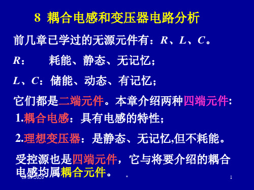
它们都是二端元件。本章介绍两种四端元件: 1.耦合电感:具有电感的特性;
2.理想变压器:是静态、无记忆,但不耗能。
受控源也是四端元件,它与将要介绍的耦合
电感均属耦合元件。
29.09.2020
b *
a、b是同名端 7
2.起的作用相同的一对端钮;
当线圈电流同时流入(或流出)该对端钮时, 各线圈中产生的磁通方向一致的这对端钮。
或者说,(1)同名端就是当电流分别流入线 圈时,能使磁场加强的一对端钮;
(2)同名端就是当电流分别流入线圈时,能 使电压增加的一对端钮;
(3)产生自感电压与互感电压极性相同的
29.09.2020
*
9
耦合电感的电路符号:
a+ i1 M i2 + c a+ i1 M i2 + c
u1
L* 1
* L2
u2
u1
L* 1
L2
u2
*
b-
- d b-
-d
VCR中互感电压取+ VCR中互感电压取-
(当各线圈的电压、电流方向关联时只有这两
种可能。)
29.09.2020
*
10
在绕法无法知道的情况下,同名端的测定:
a+ i1
u1
L 1
M d i2
b-
dt
i2
L 2
M di 1 dt
+ c a+
u2 u1
- d b-
i1
L 1
M d i2 dt
- 1、下载文档前请自行甄别文档内容的完整性,平台不提供额外的编辑、内容补充、找答案等附加服务。
- 2、"仅部分预览"的文档,不可在线预览部分如存在完整性等问题,可反馈申请退款(可完整预览的文档不适用该条件!)。
- 3、如文档侵犯您的权益,请联系客服反馈,我们会尽快为您处理(人工客服工作时间:9:00-18:30)。
Vout
= Vc1
+ Vc2
+ Vc3
= Vs
2 1− D
(3)
where, n is assumed to 1. If the voltage multiplier is increased, the output voltage can be expressed as the sum of voltages of output capacitors as follows:
Vc3
= Vs
1 1− D
,
D
=
Ton Ts
(1)
where, D is the duty ratio, Ton is the pulse width, Ts is the
switching period. Also, the capacitor voltage Vc1 and Vc2
can be expressed as follows:
VC1
= VS
nD 1− D
, VC 2
=
nVs
(2)
where, n is turn ratio of L2/L1. Using (1) and (2), the
0-7803-9252-3/05/$20.00 ©2005 IEEE
567
output voltage can be expressed as follows:
Vout
= Vc1
+ Vc2
+ L + Vcn
= Vs
1+ k 1− D
(4)
where, k is the number of voltage doubler. With very low duty cycle, Vc2 can not be the product of turn ratio and input voltage because C2 can not be charged fully due to very short duty cycle. If the turn-on time ends prior to the charging of capacitor C2 to nVs, output voltage will be decreased in proportional to the charging voltage of C2. In this case, it is assumed that the duty cycle is enough to guarantee the charging time of C2. In the figure 1, k is 1. k is increased in proportion to the multiplier number. Figure 2 shows the boost rate of output voltage using the circuit of figure 1 with a continuous inductor current. In this case, input voltage has been set to 48V. Figure 2 shows the results not only for different number of multiplier but also for turn ratio at the same time. That is, if turn ratio is n, (4) can be expressed as follows:
switch, and simple topology. This topology can be modified to the different variants as described in [7].
This paper presents an improved high boost converter that can boost very low input voltage to high output voltage. The proposed circuit is made of a boost converter with a coupled inductor and a voltage multiplier. The number of multiplier can be adjusted to get a needed duty ratio; a higher boost rate is easily obtained from the voltage multiplier. In this paper, a 300W prototype is made and tested to verify and analyze the operation of the proposed topology.
With a very high duty ratio, the output rectifier conducts only a very short time during each switching cycle, thus resulting in serious reverse recovery problems and an increase in the rating of the rectification diode. Also, the EMI problem is severe under this condition. Therefore, a number of modified boost converter topologies have been proposed to get higher conversion efficiency and voltage gain.[2-7]
High Boost Converter Using Voltage multiplier
Ju-Won Baek, Myung-Hyo Ryoo, Tae-Jin Kim, Dong-Wook Yoo, Jong-Soo Kim
Industrial Electric Research Center Korea Electrotechnology Research Institute 28-1, SungJudong, Changwon, Kyungnam
I. INTRODUCTION
Reliability becomes more important to power supplies for industrial applications. So, power supplies have adopted a battery back-up system in several applications. In addition to that, renewable energy such as the fuel cell is a hot issue in the research field. The common power supply for the above applications is a high boost converter to step up the low input voltage to high output voltage. Usually, a high efficiency, high step up dc/dc converter that can generate 380Vdc bus from 48Vdc plant is one of the most important part for DC back up system and fuel cell application. [1]
D3
L2
C1
L1
D2
C2
. 1 the proposed high boost circuit
II. CONFIGURATION AND OPERATION PRINCIPLE
A. Circuit Configuration
Figure 1 shows the proposed high boost converter. A pair of inductors is coupled magnetically and a secondary side of coupled inductors is rectified using a voltage multiplier. The multiplier can consist of various types. In this case, a voltage doubler is used. If the inductor current is continuous, the capacitor voltage Vc3 can be expressed as follows:
Generally, the conventional method to step up the output voltage is using a transformer. In this case, additional losses caused by the transformer and the switch are generated. The modified boost converter using inductor coupling is better compared to the conventional high boost converter such as a cascade boost converter and a converter using a transformer.[4-6] The main features of these converters are a high conversion ratio, high efficiency, a single low voltage
