12位可编程磁旋转编码器
霍尔旋转编码器的选型

产品目录编码器..............................................................................................................................- 1 - HAE18绝对型旋转编码器............................................................................................- 1 - HAE28绝对型旋转编码器............................................................................................- 4 - HAE38绝对型旋转编码器............................................................................................- 7 - HAN18模拟输出旋转编码器......................................................................................- 10 - HAN28模拟输出旋转编码器......................................................................................- 12 - HPE18增量型旋转编码器..........................................................................................- 14 - HPE28增量型旋转编码器..........................................................................................- 17 - HPE38增量型旋转编码器..........................................................................................- 20 - MPE28微功耗脉冲式编码器......................................................................................- 23 - 按钮开关........................................................................................................................- 24 - HSB分体式霍尔开关磁性按钮...................................................................................- 24 - 功率传感器....................................................................................................................- 27 - MPF电机功率传感器...................................................................................................- 27 - MQ三相电机相序&缺相传感.....................................................................................- 30 -编码器HAE18绝对型旋转编码器特点● 非接触式传感技术 ● 绝对值8、10、12位 ● 电源电压3V 或5V ● 串行数据输出SSI● 本体与外壳一体化结构、强度高 ● 耐环境、耐振、防护等级高● 结构紧凑、体积小、壳体直径仅18mm ● 内置两组滚珠轴承、适合工业环境电气参数机械参数轴承 启动力矩转子惯量 轴容许载荷 容许转速 材质 重量 2组密封 滚珠轴承≤3Ncm≤1gcm 2径向10N 轴向5N3600rpm (机械承受)壳体:铝合金或 不锈钢或铜镀镍 轴:不锈钢铝合金约30g 铜或不锈钢约40g (含标准线)环境条件使用环境温度保存环境温度防护等级耐振动耐冲击-40~+85℃ -40~+85℃IP65 10g(10~2000Hz) 100g (6mS )时序图z 8位:CLK 1 2 3 4 5 67 8910111213141516 17 18 192021读DO L OCK D7D6D5 D4 D3 D2D1D0注释状态位1有效角度值分辨率 电气转角 输出信号 上电响应读取时钟电源屏蔽线 256(8位) <2mS 5V ±10%、16mA 1024(10位) <60mS 4096(12位)360° (机械转角无停止位)串行数据 SSI<80mS≤1MHz3.3V ±10%或 5V ±10%、20mA标准0.3m 特殊0.5mz 10位:z 12位:状态位具有下列配置时才有效OCF COF LIN MagINC MagDEC EvenPAR0 00 11 0 0 1 01~15位的偶校验和符号最小 最大 单位t DO active 100 ns t CLK FE 500 ns T CLK/2 500 ns t DO valid 375 ns t DOtristate 100 ns t CSn 500 ns f CLK >0 1 MHz输出接口电路VDO CLK CS V / V P接线定义电源正Vc电源负0V输入CS 输入CLK输出DO 屏蔽线EAR红黑黄蓝绿粗黑注:屏蔽线内部未接壳体。
MCT8000F88100F88200F8系列运动控制器
版权声明 深圳市摩信科技有限公司 保留所有权力
深圳市摩信科技有限公司(以下简称摩信科技)保留在不事先通知的情况下, 修改本手册中的产品和产品规格书的权力。摩信科技不承担由于使用本手册或本 产品不当,所造成直接的、间接的、特殊的、附带的或相因而生的损失或责任。 摩信科技具有对本产品的专利权、版权和其它知识产权。未经授权,不得直接或 者间接地制造、加工使用本产品及其相关部分。
警告:运动中的机器有危险!使用者有责任在机器中设计有效的出错处理和 安全保护机制,摩信科技没有义务或责任对由此造成的附带的或相因而生的损失 负责。
目录
目录
第一章 绪论……………………………………………………………………………………..…(1)
1.1 概述......................................................................................………………………………..(1) 1.2 电机类型简介...............................................................................……………………….…(2)
绪论
第一章 绪 论
1.1 概述
MCT8000F8/8100F8/8200F8系列控制器可以通过ISA/PCI总线或USB接口直接 与PC机相连接,不同型号的控制器连接方式不同。其中,MCT8000F8系列的接口 为ISA总线,MCT8100F8系列为PCI总线,而MCT8200F8是USB接口。由于采用了最 新的DSP和FPGA技术,这些控制器都具有高速通信功能、高频率的编码器计数功 能和低电磁辐射等特点。经过特殊的设计,所有的MCT8000F8/8100F8/8200F8控 制器都能基于主机运行或者脱离主机独立运行。借助于MCT8000F8的软件包,控 制器可以自动选择本地或互联网两种方式运行。有关详细情况可参考 《MCT8000FX/8100FX/8200FX系列运动控制器:软件使用手册》。
旋转变压器编码器的工作原理
旋转变压器编码器的工作原理
旋转变压器编码器的工作原理是基于电磁感应原理和变压器原理。
它是一种常见的传感器,用于测量和记录旋转物体的位置、速度和方向。
旋转变压器编码器由两部分组成:固定部分和旋转部分。
固定部分包括一个绕组和一个磁芯,而旋转部分包括一个磁头和一个磁环。
当旋转部分绕着固定部分旋转时,磁头和磁环之间的磁场会发生变化,从而在绕组中引起感应电动势的变化。
具体来说,当旋转部分转动时,磁头和磁环之间的距离会发生变化。
这会导致磁场的强度和方向在绕组中发生变化,进而引起感应电动势的变化。
感应电动势的大小和方向取决于旋转部分的位置和方向。
编码器通过测量感应电动势的变化来确定旋转物体的位置、速度和方向。
通常使用数字输出来表示这些信息。
编码器通常具有一个输出轴和一个编码盘,编码盘会根据旋转部分的位置和方向而旋转。
通过读取编码盘上的编码信号,可以确定旋转物体的具体位置及其旋转方向。
旋转变压器编码器具有很高的精度和可靠性,被广泛应用于自动控制系统、机器人、摄像机云台、工业机械等领域。
它在角度测量、位置反馈和控制系统中发挥着重要作用。
通过使用旋转变压器编码器,工程师可以实时监测和控制旋转物体的运动,从而提高系统的性能和效率。
20位+12位多圈编码器的意思
20位+12位多圈编码器是指一种精密的旋转位置传感器,它具有高分辨率、高精度和高稳定性的特点。
在工业自动化、机器人、数控机床等领域,多圈编码器广泛应用于测量转子的旋转角度和速度,以及监控机械运动的精度和稳定性。
下面我将从几个关键点来介绍20位+12位多圈编码器的意义。
1. 高分辨率20位+12位多圈编码器的“20位”和“12位”分别表示编码器的轴承环和编码盘的位数,总位数为32位。
这意味着编码器可以将360°的旋转角度分成2^32个等分,因此具有非常高的分辨率。
这种高分辨率可以精准地测量转子的微小旋转角度,满足高精度机械设备对角度测量精度的要求。
2. 高精度多圈编码器的高分辨率也给予了它高精度的特点。
通过更细微的角度刻度,编码器可以精确地识别和测量转子的微小运动和变化。
这对于一些对位置控制和速度控制要求很高的设备非常重要,比如数控机床、精密仪器等。
3. 高稳定性多圈编码器在工作过程中具有较高的稳定性。
其结构设计合理,材料选用优质,因此具有较强的抗干扰能力和长期稳定的性能。
无论是在高速运转下,还是在恶劣的工作环境下,多圈编码器都能保持稳定的测量精度和可靠的性能。
4. 应用领域20位+12位多圈编码器广泛应用于各种工程领域。
在工业自动化中,它可以用于控制系统的位置反馈和速度反馈,实现精确的运动控制和定位控制。
在机器人领域,多圈编码器可以帮助机器人精确定位和精确运动,提高其工作效率和灵活性。
在数控机床和精密加工领域,多圈编码器可以实现高精度的加工控制和高效率的生产。
多圈编码器还应用于医疗设备、航空航天、通信设备等领域。
20位+12位多圈编码器具有高分辨率、高精度和高稳定性的特点,适用于需要精确位置和速度测量的领域,对工程技术和科技发展具有重要意义。
多圈编码器的高分辨率和高精度属性使其成为现代工业自动化和机器人领域中不可或缺的设备。
它可以准确地测量转子的旋转角度和速度,确保设备的运行精度和稳定性。
AMS磁编码器产品简介完整版前期
混合式编码器(10bit)
• AS5040
• 输出方式 绝对SSI输出 绝对PWM输出 两路正交A/B及Index输出 BLDC换向 • 典型应用 叉车 电位计 旋钮 AS5040 Block Diagram
混合式绝对值编码器
• 混合式绝对值编码器,它输出两组信息:一组信 息用于检测位置,带有绝对信息功能;另一组则 完全同增量式编码器的输出信息。
多圈绝对值编码器
• 从单圈绝对值编码器到多圈绝对值编码器 • 旋转单圈绝对值编码器,以转动中测量光电码盘各道刻线,以获取唯 一的编码,当转动超过360度时,编码又回到原点,这样就不符合绝 对编码唯一的原则,这样的编码只能用于旋转范围360度以内的测量, 称为单圈绝对值编码器。 • 如果要测量旋转超过360度范围,就要用到多圈绝对值编码器 • 编码器生产厂家运用钟表齿轮机械的原理,当中心码盘旋转时,通过 齿轮传动另一组码盘(或多组齿轮,多组码盘),在单圈编码的基础 上再增加圈数的编码,以扩大编码器的测量范围,这样的绝对编码器 就称为多圈式绝对编码器,它同样是由机械位置确定编码,每个位置 编码唯一不重复,而无需记忆。 • 多圈编码器另一个优点是由于测量范围大,实际使用往往富裕较多, 这样在安装时不必要费劲找零点, 将某一中间位置作为起始点就可 以了,而大大简化了安装调试难度。
名词解释
• SSI 同步串行接口,用于串行数据传输。
接口线包括CSn片选信号线、CLK时钟信号线、DO数据信号线
名词解释
• PWM输出 即脉宽调制输出(以AS5045为例)
AS5045为12位可编程磁编码器,提供一个PWM输出,其占空比与所测量 的角度成正比:
磁式编码器技术在恶劣环境下的优势
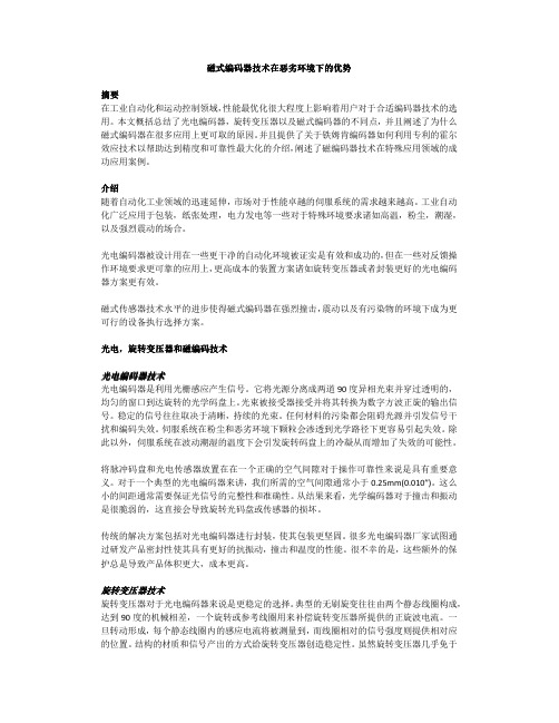
磁编码器对于撞击和振动有着固有的可抗性。比起光电编码器,传感器和磁码盘之间的间隙 可以达到 4mm(0.157”),这丝毫不影响信号的准确度。磁编码器可以在轴端余隙运行,径向跳 动的总公差高达 2.5mm(0.98”),这大大减少了码盘和传感器撞击损坏的可能性。
MPS 编码器集成电路提供轴转动时的位置和速度反馈。具有优势的离轴设计方案使得它的 安装区域更紧凑。
Schneider 步进电机以前使用的方案是带有外部光电编码器的远程驱动,用一根电缆连接到 电机端。这显然易受到噪声和碎污染物的影响。而这些挑战都被 MPS 编码器电路板一一克 服,因为其紧凑的传感器能直接安装在嵌入的电机电子内部。
增量式分辨率 1024lines
N/A
典型的 10000 线∕可
能 250k 线
25000 线
典型的精度
(角分)
30 to 50
3 to 50
0.15 to 6
4 to 20
间隙/校准要
求
敏感
敏感
很敏感
不敏感
能否经受间隙
有污染物 Y
Y
N
Y
能够经受撞击
和粉尘
Y
Y
N
Y
所能承受的最
高温度
125° C
150° C
工业环境的危害,但其控制系统的成本往往比光电和磁式编码器高很多。他们需要一个分解 器将数字整流器集成到电路上并放置在较远的区域,这样需要提供布线来执行低级信号。布 线会增加安装的复杂性,安装维护起来也不方便。
基于可编程逻辑器件的数字电路实验箱设计与实现
- 137 -第7期2019年4月No.7April,2019目前,国内众多高校电子信息相关专业都设有数字电路实验室作为数字电路课程的实践场所,实验设备使用频繁,所以实验准备的工作量也很繁琐,设备维护较为麻烦[1]。
另外,传统实验所用器件基本停产,购买麻烦,且价格高昂,损坏也比较严重,所以每学期都需要较多的经费对器件进行更换和维修,以保证实验器材正常使用。
随着实验内容的增加,实验箱体积越来越大,功耗也大大增加,往往难以适应大规模、不同内容实验的要求。
实验装置的落后已成为阻碍实验发展的重要因素之一[2]。
由此,为取代原有繁多的传统器件,减小实验箱的体积,应该选用FPGA 或者CPLD 代替。
选用verilog 编写的程序作为数字芯片的主要核心,在此基础上做出更多常用数字芯片的程序。
需用到的数字芯片,只需下载想用的程序即可实现相应的功能。
改动之后不但能节省分立元器件成本,还可使实验箱的功能更加强大,灵活性更高。
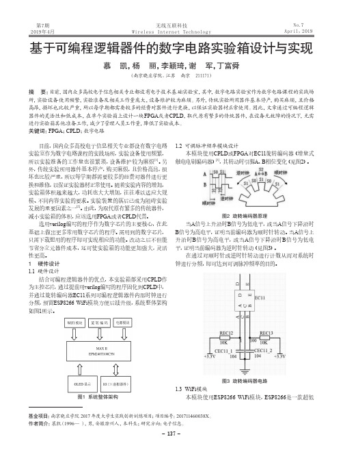
1 硬件设计1.1 硬件设计结合可编程逻辑器件的优点,本实验箱都采用CPLD 作为主控芯片,通过提前用verilog 编写的程序固化到CPLD 中,并通过旋转编码器EC11系列可编程逻辑器件内部时钟进行分频,预留ESP8266 WiFi 模块方便后续升级,系统整体架构如图1所示。
图1 系统整体架构1.2 可调脉冲频率模块设计本模块使用CPLD 或FPGA 对EC11旋转编码器(增量式触电电刷编码器)[3],其转动时引脚A 、B 相位变化(见图2)。
图2 旋转编码器原理当A 信号上升沿时B 信号为低电平,或当A 信号下降沿时B 信号为高电平,证明当前编码器为顺时针转动。
当A 信号上升沿时B 信号为高电平,或当A 信号下降沿时B 信号为低电平,证明当前编码器为逆时针转动(见图3)。
在通过对顺时针或逆时针转动进行计数从而对系统时钟进行分频,即可达到可调脉冲频率的目的。
图3 旋转编码器电路1.3 WiFi 模块本模块使用ESP8266 WiFi 模块,ESP8266是一款超低基金项目:南京晓庄学院2017年度大学生实践创新训练项目;项目编号:201711460038X 。
IC资料-AS5045中文资料

参数
符号
最小值
最大值
单位 注释
高电平输出电压 低电平输出电压
输出电流
VOH
VDD5V-0.5
VOL
VSS+0.4
4 IO
2
V
V
mA
VDD5V: 4.5V
mA
VDD5V: 3V
3.4.5 CMOS 三态输出:DO
(工作条件:Tamb = -40 至 +125°C, VDD5V = 3.0-3.6V (3V 工作方式) VDD5V = 4.5-5.5V (5V 工作方式),除非另有规定)
2 引脚配置
MagINCn
1
MagDECn
2
NC
3
NC
4
NC
5
Mode
6
VSS
7
Prog_DI
8
AS5045
16
VDD5V
15
VDD3V3
14
NC
13
NC
12
PWM
11
CSn
10
CLK
9
DO
图 2:引脚配置 SSOP16P16
2.1 引脚说明
表 1 对标准的 SSOP16 封装(收缩型小外形封装,16 引线,本体尺寸:5.3mm x 6.2mm;参见图 2)的每 一个引脚进行了说明。
Tamb
-40
Isupp
VDD5V 4.5 VDD3V3 3.0
VDD5V 3.0 VDD3V3 3.0
125 °C -40°F…+257°F
16
21 mA
5.0
5.5
V 5V工作方式
3.3
3.6 V
ENI-1024 增量磁旋转编码器 KIT 用户手册和安装指南说明书

ENI-1024Incremental magnetic rotary encoder KITUser’s Manual and Installation GuideContents1. Safety, policy and warranty.1.1. Safety notes.1.2. Policy.1.3. Warranty.2. Electric specifications.2.1. Operation ranges.2.2. Incremental channels signals.2.3. Differential outputs.2.4. LED indicator.3. Installation guide.3.1 . Description of working.3.2 . Pinout of the connector.3.3 . Installation of the device.1. Safety, policy and warranty.1.1. Safety NotesThe device should not be used where it can cause personal injury, death or high financial loss.1.2. PolicyCNCdrive cannot take responsibility for any personal injury and/or financial loss caused by their devices failure or caused by following an error in this documentation.1.3. WarrantyWe give 12 months of standard warranty period with our ENI-1024 KIT encoders. Customers may send back the device within 15 days from reception date if they are not satisfied with the performance.Using the devices outside of the specified electrical ranges may cause permanent damage to the device and voids warranty.ESD notice: Use ESD protection gloves when installing the device.ESD damage caused by human body discharge to the device excludes from warranty.2. Electric specifications.2.1.Operation ranges.Property Min Typ Max Unit NotesSupply voltage4.5 55.5 VDCSupply current 38 mA Outputs not connectedHigh level output current-20 mALow level output current20 mAEncoder resolution - 1024 - Counts perrevolution In 4X decoding mode. Counting A and B channels’ both the rising and the falling edges.Maximum countfrequency512 kHzHysteresis 2 Counts Hysteresis introduced to avoid flickering of the encoder outputsDifferential non-linearity +-0.176 degreesIntegral non-linearity +-1.4 degrees With magnet displacementof 0.485mm out of thecenter of the sensor. Maximum alloweddisplacement of magnet from center of the sensor. 0.485 mmMeasured on the radiusfrom center of the sensorIC.Ambient temperaturerange-55 +85 °C2.2. Incremental channel signals.The device outputs 90°shifted incremental A and B channel signals. The signal A leads signal B in one rotational direction and signal B leads A in the opposite rotational direction of the magnet. In addition an index signal output is provided which signal is produced on the zero mechanical position, one LSB pulse width and one pulse per full revolution duration.The following figure shows the encoder signals:To avoid the flickering of the encoder signals a 2 counts (LSB) length of hysteresis is introduced.The following figure shows the 2 counts hysteresis:2.3. Differential outputs.All output signals A and B and Index are output as differential signals. This means that each signal has it's negated output too. The differential signals can be transferred in twisted wire pairs to long distance. The differential outputs are produced with the onboard 26LS31 differential line driver chip.The following figure shows the A and _A channel signals in normal operation (when counting) and also in an external short circuit of the wires. The figure is similar for B to _B and for Index to _Index channels:2.3. LED indicator.The device has one LED on the top (connector) side of the panel. The LED indicates if the magnet used for the position sensing is in the correct range for the device to read the mechanical position. If the magnet is in the correct range (1-2mm distance from the surface of the sensor IC) then the LED lights. If the magnet is out of the good range (too close or too far) then the LED light goes off. The sign of the LED makes the correct alignment of the magnet easy to check.3. Installation guide.3.1. Description of working.The device is a rotary encoder module for position sensing in rotary motion. The aluminium hub which includes a magnet at it's end can be attached to a motor shaft. To make the device working place the printed circuit board of the module above the magnet keeping 1-2mm distance with the magnet centered to the center mark on the PCB. The device producing differential incremental A and B channel signals, 1024 edges per full revolution of the magnet. In addition there is an index and _Index output with one counts output per every full rotation. The output signals can be used to measure the relative position of the rotation.The following picture shows the bottom of the printed circuit board with the sensor IC located in the center of the PCB:3.2. Pinout of the connector.The device has a 10 pin IDC crimpable connector. This connector is used to connect the5Volts to power the device and to route out the incremental output signals.The connector is crimpable to a 10 pin ribbon cable or for example to wires of a CAT5/6 patch cable.The following picture and diagram shows the pinout of the connector:Pin number Description1 Ground power input2 +5Volts power input3 Index signal output4 _Index signal output5 A signal output6 _A signal output7 B signal output8 _B signal output9 NC. No internal connection10 NC. No internal connection3.3. Installation of the device.To following steps should done to install the device:a.) Make 2pcs of tapped M3 drills around the motor backshaft (or to the shaft of the installation). The tapped drills should be made on a 25.4 (1 Inch) circle around the midpoint of the shaft on a line alignment (180°) to eachother.b.) Place the magnet holder hub to the motor's backshaft. The hub is pre-drilled with 3mm diameter and should be drilled up if nessessary. Drilling it up can be made on a drillpress with a standard HSS drilling tool. Take care to not drill into the magnet located at the other end of the hub.c.) bolt in the hexagonal spacers to the tapped holes done in point a.d.) crimp your cable to the connector on the encoder PCB.e.) Place the encoder PCB to the top of the hexagonal spacers with the ICs facing down and the connector and LED facing upward. Bolt the PCB to the top of the hexagonal spacers with the supplied M3 screws through the 3mm drills on the PCB.f.) Adjust the hub on the shaft with keeping a 1-2mm distance of the magnet on the hub end to the IC surface on the PCB. Lock the hub to the shaft with bolting the screw located in the side of the hub.g.) Power up the device with providing 5Volts Voltage to it's power pins and check the LED on the top of the PCB. The LED continious on state means a correct alignment of the magnet. If the LED is off after powered means the magnet is out of the correct range and needs to be aligned.For more information visit:e-mail: info@cncdrivePlease consider the enviroment before printing this document.。
AS5040中文版
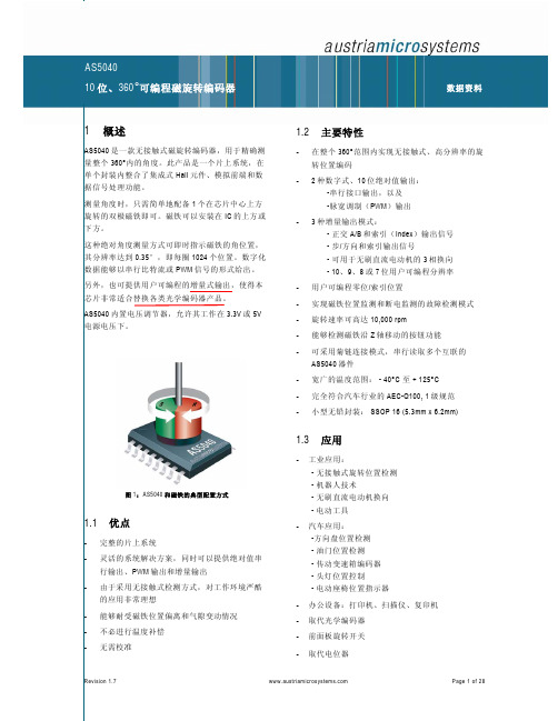
CSn 接逻辑高电平时,可将数据输出引脚(DO)置 为三态,并终止串行数据传输。脚也用于对准模式 (见第 19 页)以及编程模式(见 14 页)
引脚 12 允许采用单根连线输出 10 位绝对位置值。 此数值被编码成脉宽调制信号,脉宽的步长为 1μs( 一整圈为 1μs 至 1024μs)。通过使用外部低通滤波 器,数字 PWM 信号可以转换成模拟电压,从而可以 直接取代电位器。
约为1kHz的脉宽调制信号;模式 3.x下为LSB
13 NC
-
必须保持开路
14 NC
-
必须保持开路
15 VDD3V3
S
3V 调节器输出(参见图 19)
16 VDD5V
S
5V 正电源电压
表 2:SSOP16 的引脚说明
DO_OD DO DI_PD DI_PU
数字输出,漏极开路 数字输出 数字输入,带下拉 数字输入,带上拉
3.3.2 CMOS / 编程输入:Prog (工作条件:Tamb = -40 至+125°C, VDD5V = 3.0-3.6V (3V 工作) VDD5V = 4.5-5.5V (5V 工作),除非另有规定)
参数 高电平输入电压 高电平输入电压 低电平输入电压 下拉高电平输入电流
符号 VIH VPROG VIL IiL
4
B_Dir_V
DO
模式2.x:旋转方向
模式3.x:V信号(相位2)
5
NC
-
必须保持开路
模式1.x和模式2.x :Index信号指
6
Index_ W
DO
AS5145B_Datasheet_v1-14_SC
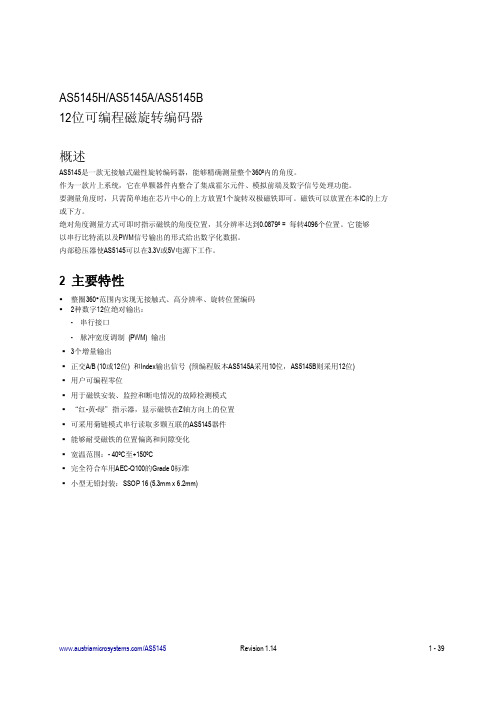
表3. 电气特性
符号 工作条件 TAMB Isupp VDD5V VDD3V3 VDD5V VDD3V3 VON 环境温度 电源电流 VDD5V引脚的电源电压 VDD3V3引脚的 电压调节器输出电压 VDD5V引脚的电源电压 VDD3V3引脚的电源电压 上电复位门限上电电压; 300mV典型滞回 上电复位门限关断电压; 300mV典型滞回 5V操作 3.0 3.3V操作 (连接VDD5V和VDD3V3引脚) 3.0 3.0 1,37 3.3V直流电源电压(VDD3V3) 1.08 1.9 2.6 3.3 3.3 3.3 2.2 3.6 3.6 3.6 2.9 V 4.5 -40 16 5.0 +150 21 5.5 V ºC mA 参数 条件 最小 典型 最大 单位
VOL
低电平输出电压
V
IO
输出电流
VOL
V
IO
输出电流
VOL
低电平输出电压
V
IO
输出电流
1.
配合3.3V或5V电源
/AS5145
Revision 1.14
7 - 39
AS5145
Datasheet - G e n e r a l D e s c r ip t io n
V
Voff 编程条件 VPROG VProgOff IPROG Rprogrammed Runprogramme
d
编程电压 编程电压关断电平 编程电流 编程熔丝电阻 (log 1) 未编程熔丝电阻 (log 0)
编程时使用的电压 线路必须放电至该电平 编程时的电流 100mV下10µA最大电流 100mV下2mA最大电流
20位+12位多圈编码器的意思

20位+12位多圈编码器的意思【原创实用版】目录1.20 位 +12 位多圈编码器的概念2.20 位 +12 位多圈编码器的构成3.20 位 +12 位多圈编码器的工作原理4.20 位 +12 位多圈编码器的应用领域5.20 位 +12 位多圈编码器的优势和局限性正文一、20 位 +12 位多圈编码器的概念20 位 +12 位多圈编码器是一种高精度的旋转测量设备,可以对旋转运动进行精确的编码和测量。
它由一个 20 位的编码器和一个 12 位的编码器组成,可以提供非常高的旋转运动测量精度。
二、20 位 +12 位多圈编码器的构成20 位 +12 位多圈编码器主要由两个编码器组成,一个是 20 位的编码器,另一个是 12 位的编码器。
20 位编码器可以提供 2 的 20 次方,即 1048576 种不同的编码,而 12 位编码器可以提供 2 的 12 次方,即 4096 种不同的编码。
这两个编码器结合在一起,可以提供非常高的旋转运动测量精度。
三、20 位 +12 位多圈编码器的工作原理20 位 +12 位多圈编码器的工作原理是基于光电效应的。
当旋转运动发生时,编码器上的光电传感器会根据旋转运动的位置发出不同的电信号,这些电信号经过处理后,就可以得到旋转运动的精确位置信息。
四、20 位 +12 位多圈编码器的应用领域20 位 +12 位多圈编码器广泛应用于各种需要精确旋转运动测量的领域,如数控机床、机器人、自动化生产线等。
五、20 位 +12 位多圈编码器的优势和局限性20 位 +12 位多圈编码器的优势在于其高精度的旋转运动测量能力,可以提供非常高的旋转运动测量精度。
增量式旋转编码器工作原理和时序图
增量式旋转编码器工作原理、在PLG单片机中应用时序增量式旋转编码器通过内部两个光敏接受管转化其角度码盘的时序和相位关系,得到其角度码盘角度位移量增加(正方向)或减少(负方向)。
在接合数字电路特别是单片机后,增量式旋转编码器在角度测量和角速度测量较绝对式旋转编码器更具有廉价和简易的优势。
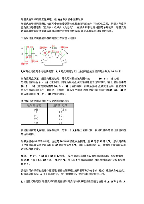
下面对增量式旋转编码器的内部工作原理(附图)A,B两点对应两个光敏接受管,A,B两点间距为S2 ,角度码盘的光栅间距分别为SO 和S1。
当角度码盘以某个速度匀速转动时,那么可知输出波形图中的SO: S1:S2比值与实际图的SO: S1:S2比值相同,同理角度码盘以其他的速度匀速转动时,输出波形图中的SO: S1:S2比值与实际图的SO: S1:S2比值仍相同。
如果角度码盘做变速运动,把它看成为多个运动周期(在下面定义)的组合,那么每个运动周期中输出波形图中的SO: S1:S2比值与实际图的SO: S1:S2比值仍相同。
我们把当前的A,B输出值保存起来,与下一个A,B输出值做比较,就可以轻易的得出角度码盘的运动方向,如果光栅格SO等于S1时,也就是SO和S1弧度夹角相同,且S2等于SO的1/2,那么可得到此次角度码盘运动位移角度为SO弧度夹角的1/2,除以所消毫的时间,就得到此次角度码盘运动位移角速度。
SO等于S1时,且S2等于SO的1/2时,1/4个运动周期就可以得到运动方向位和位移角度,如果SO不等于S1,S2不等于SO的1/2,那么要1个运动周期才可以得到运动方向位和位移角度了。
我们常用的鼠标也是这个原理哦根据检测原理,编码器可分为光学式、磁式、感应式和电容式。
根据其刻度方法及信号输出形式,可分为增量式、绝对式以及混合式三种。
1.1增量式编码器增量式编码器是直接利用光电转换原理输出三组方波脉冲A、B和Z相;A、B两组脉冲相位差90o,从而可方便地判断出旋转方向,而Z相为每转一个脉冲,用于基准点定位。
它的优点是原理构造简单,机械平均寿命可在几万小时以上,抗干扰能力强,可靠性高,适合于长距离传输。
foc 磁编码器 旋转总角度
标题:FOC 磁编码器在旋转控制系统中的应用随着现代工业技术的不断发展,磁编码器作为一种高精度、不受环境干扰的角度测量装置,在工业自动化控制系统中得到了越来越广泛的应用。
其中,FOC 磁编码器作为一种新型的磁编码器,在旋转控制系统中具有独特的优势。
本文将重点分析FOC 磁编码器在旋转控制系统中的应用,从其工作原理、优势特点、应用案例等方面进行深入探讨。
一、FOC 磁编码器的工作原理FOC 磁编码器是一种基于磁感应原理的角度测量装置。
其工作原理是利用固定在旋转轴上的磁栅和安装在外部固定位置的霍尔传感器之间的磁场变化来实现角度测量。
通过磁场的变化,FOC 磁编码器可以精确地测量出旋转轴的角度,并输出相应的数字信号。
二、FOC 磁编码器的优势特点1. 高精度:FOC 磁编码器采用了先进的霍尔传感器技术,能够实现高精度的角度测量,通常可以达到几十个角度的分辨率。
2. 抗干扰能力强:FOC 磁编码器采用了磁栅和霍尔传感器结合的方式,不受外部环境磁场的影响,抗干扰能力强,适用于复杂的工业环境。
3. 快速响应:FOC 磁编码器采用了高速数字信号处理技术,能够实现快速的角度测量和输出,适用于高速旋转控制系统。
4. 耐用稳定:FOC 磁编码器采用了高质量的磁感应元件和工艺,具有良好的耐用性和稳定性,可以长期稳定地工作。
三、FOC 磁编码器在旋转控制系统中的应用案例1. 机器人关节控制系统:FOC 磁编码器可以配合机器人关节驱动系统,实现对机器人关节角度的精确控制和监测,提高机器人的运动精度和稳定性。
2. 电动汽车驱动系统:FOC 磁编码器可以应用在电动汽车的驱动系统中,实现对电机旋转角度的精准控制,提高电动汽车的能效和动力性能。
3. 工业生产线旋转装置:FOC 磁编码器可以用于工业生产线上的旋转装置的控制系统中,监测旋转角度并实现精准的位置控制,提高生产线的自动化程度和生产效率。
四、总结FOC 磁编码器作为一种新型的角度测量装置,在旋转控制系统中具有独特的优势和广阔的应用前景。
HENGSTLER 编码器 说明书

编码器■绝对值型我们是您最理想的全球合作伙伴,为您提供创新产品。
HENGSTLER 产品编码器绝对值型编码器ACURO驱动和ACURO工业型增量型编码器防爆型和不锈钢型总线编码器工业计数器和控制器从微型计数器到大型的控制计数器,多功能计数器,带接口的计数器、位置计数器、计时器、转速计打印机和切纸机打印机解决方案,如信息中心、售票机、自动提款机、POS系统,模块化热式打印机和针式打印机应用,附件如卷纸器和切纸机。
继电器技术主要致力于全球大部分通用安全继电器- 继电器带导向触点组 -其它产品如:双稳继电器,隔离继电器,高电压继电器,微型切换继电器丹纳赫传感器与控制集团的其它品牌编码器 计数器 指示器 继电器 打印机 切纸机Harowe TM Namco TMNorthStar TMPartlow TMVeeder-Root TM West TMDynapar TMEagle Signal TM ENMTM与Hengstler合作的理由位于Aldingen市的Hengstler总部Hengslter总部位于德国西南部的Aldingen市,靠近Black Forest-该地区是德国工业先驱和投资者的聚集地。
其中包括Hengstler公司的创建者Johannes Hengstler,他于1846年所开设的工厂,后来成为Hengstler集团的中心所在地。
工厂最初从事钟表弹簧的制造;现在Hengslte从事从微型计数器到绝对值型空心轴编码器等各种产品的制造。
更具竞争性本产品目录足以见证我们在编码器领域中所具有的竞争性-(所有Hengstler产品)采用最先进技术、最佳设计方案、最高质量和可靠性标准的综合方案。
Hengstler——值得您信赖本手册中的所有技术数据和信息(包括图纸) 经过我们精心地收集和编排。
本手册提供了产品及附件的信息,但并不构成技术数据或功能的任何担保。
产品用户必须自行判断产品的适用性。
我们有权修改所有技术数据。
各种编码器的种类及应用

各种编码器的种类及应用编码器是一种用于将输入信号转换为特定编码形式的设备或系统,其本质是一种信息转换的过程。
根据不同的应用领域和需求,编码器有多种不同的类型。
以下将介绍几种常见的编码器类型及其应用。
1. 绝对值编码器绝对值编码器可以将输入信号转化为特定的离散数值,每个数值代表一个确定的位置。
常见的绝对值编码器有光电编码器、磁性编码器和接触式编码器等。
应用领域:绝对值编码器广泛用于机械控制系统中,如数控机床和机器人等,用于测量和控制位置信息。
2. 增量编码器增量编码器输出的编码信号是关于位置变化的增量量。
在每个位置变化时,增量编码器会输出一个脉冲信号,可以通过计数这些脉冲信号来测量位置变化的大小。
应用领域:增量编码器常用于测量转速和角度变化,广泛应用于机械设备和自动化系统中,如汽车发动机、风力发电机组等。
3. 旋转编码器旋转编码器是一种用于测量旋转物体角度和方向的编码器。
它通常有两个输出通道,一个用于测量角度大小,另一个用于测量旋转方向。
应用领域:旋转编码器常用于手动控制设备,如电子游戏手柄、机械表盘等。
此外,旋转编码器还广泛应用于汽车、机械设备和机器人等领域。
4. 数字编码器数字编码器基于数字电子技术,将输入信号转化为数字形式的编码输出。
数字编码器通常具有较高的精度和可靠性,并且能够通过数字信号处理实现更高级的功能。
应用领域:数字编码器广泛用于自动化控制系统、数字通信系统、数字音频设备等领域。
如工业自动化系统中的位置控制、机器人控制等。
5. 视觉编码器视觉编码器通过图像传感器对图像进行捕捉和处理,将图像信息转化为编码输出。
视觉编码器的主要优点是能够实现非接触测量和高精度测量。
应用领域:视觉编码器广泛应用于计算机视觉、机器人视觉、图像处理等领域。
如机器人的导航和定位、物体识别和测量等。
6. 频率编码器频率编码器是一种将输入信号转化为频率输出的编码器。
通过测量输出的脉冲信号频率,可以获取输入信号的频率大小。
多圈磁编码器 原理
多圈磁编码器原理
多圈磁编码器是一种常用的角度测量设备,其原理基于磁性传感器和磁性标尺。
多圈磁编码器通常由两部分组成:磁性标尺和磁性传感器。
磁性标尺是一种具有多个等分刻度的磁性环,通常由磁性材料制成。
这些刻度可以表示出一个完整的圆周,每个刻度代表一定的角度。
磁性传感器是一种能够测量磁场变化的设备。
在多圈磁编码器中,磁性标尺固定在要测量的物体上,而磁性传感器则与之相对位置固定,使其能够感受到磁场的变化。
当物体旋转时,磁性标尺上的磁场也会随之改变。
磁性传感器可以通过检测磁场的变化,来计算出物体的角度。
具体来说,磁性传感器会测量磁场的强度和方向,然后将这些数据转换成对应的角度值。
多圈磁编码器具有高精度和较大的测量范围,适用于需要高精度角度测量的应用场景。
它常被用于机械设备、工业自动化和机器人技术等领域。
- 1、下载文档前请自行甄别文档内容的完整性,平台不提供额外的编辑、内容补充、找答案等附加服务。
- 2、"仅部分预览"的文档,不可在线预览部分如存在完整性等问题,可反馈申请退款(可完整预览的文档不适用该条件!)。
- 3、如文档侵犯您的权益,请联系客服反馈,我们会尽快为您处理(人工客服工作时间:9:00-18:30)。
AS5145/AS5145A/AS5145B12-Bit Programmable Magnetic Rotary Encoder D a t a S h e e t1 General DescriptionThe AS5145 is a contact less magnetic rotary encoder for accurate angular measurement over a full turn of 360 degrees.It is a system-on-chip, combining integrated Hall elements, analog front end and digital signal processing in a single device.To measure the angle, only a simple two-pole magnet, rotating over the center of the chip, is required. The magnet may be placed above or below the IC.The absolute angle measurement provides instant indication of the magnet’s angular position with a resolution of 0.0879º = 4096 positions per revolution. This digital data is available as a serial bit stream and as a PWM signal.An internal voltage regulator allows the AS5145 to operate at either 3.3V or 5V supplies.2 Key FeaturesContact less high resolution rotational position encoding over a full turn of 360 degreesTwo digital 12 bit absolute outputs:-Serial interface-Pulse width modulated (PWM) outputFigure 1. AS5145 Automotive Rotary Encoder ICThree incremental outputsQuadrature A/B (10 or 12 bit) and Index output signal (pre-programmed versions available AS5145A for 10 bit andAS5145B for 12 bit)User programmable zero positionFailure detection mode for magnet placement, monitoring, and loss of power supplyRed-Yellow-Green indicators display placement of magnet in Z-axisSerial read-out of multiple interconnected AS5145 devices using Daisy Chain modeTolerant to magnet misalignment and gap variationsWide temperature range: - 40ºC to +150ºCFully automotive qualified to AEC-Q100, grade 0Small Pb-free package: SSOP 16 (5.3mm x 6.2mm)3 ApplicationsThe device is ideal for industrial applications like contactless rotary position sensing and robotics; automotive applications like steering wheel position sensing, transmission gearbox encoder, head light position control, torque sensing, valve position sensing and replacement of high end potentiometers.Hall Array& Front end AmplifierPWMInterfaceDSPOTPRegisterMagINCnDOCSnCLKPDIOSinCosMagAngMagDECnPWMAbsoluteInterface(SSI)V DD5VIncremental Interface DTEST1_A DTEST2_BLDO 3.3VV DD3V3MuxMode_IndexAS5145Contents1 General Description (1)2 Key Features (1)3 Applications (1)4 Pin Assignments (4)4.1 Pin Descriptions (4)5 Absolute Maximum Ratings (6)6 Electrical Characteristics (7)6.1 Magnetic Input Specification (8)6.2 System Specifications (9)7 Timing Characteristics (11)8 Detailed Description (12)8.1 Mode_Index Pin (12)8.1.1 Synchronous Serial Interface (SSI) (13)8.1.2 Incremental Mode (14)8.1.3 Sync Mode (16)8.1.4 Sin/Cosine Mode (16)8.1.5 Daisy Chain Mode (16)8.2 Pulse Width Modulation (PWM) Output (17)8.2.1 Changing the PWM Frequency (18)8.3 Analog Output (18)9 Application Information (19)9.1 Programming the AS5145 (19)9.1.1 Zero Position Programming (19)9.1.2 OTP Memory Assignment (20)9.1.3 User Selectable Settings (20)9.1.4 OTP Default Setting (21)9.1.5 Redundancy (21)9.1.6 Redundant Programming Option (22)9.1.7 OTP Register Entry and Exit Condition (22)9.2 Alignment Mode (23)9.3 3.3V / 5V Operation (23)9.4 Selecting Proper Magnet (24)9.4.1 Physical Placement of the Magnet (25)9.4.2 Magnet Placement (26)9.5 Simulation Modeling (26)9.6 Failure Diagnostics (27)9.6.1 Magnetic Field Strength Diagnosis (27)9.6.2 Power Supply Failure Detection (27)9.7 Angular Output Tolerances (27)9.7.1 Accuracy (27)9.7.2 Transition Noise (29)9.7.3 High Speed Operation (29)9.7.4 Propagation Delays (29)9.7.5 Internal Timing Tolerance (30)9.7.6 Temperature (30)9.7.7 Accuracy over Temperature (30)9.8 AS5145 Differences to AS5045 (30)10 Package Drawings and Markings (32)10.1 Recommended PCB Footprint (33)11 Ordering Information (35)4 Pin Assignments4.1 Pin DescriptionsThe following SSOP16 shows the description of each pin of the standard SSOP16 package (Shrink Small Outline Package, 16 leads, body size: 5.3mm x 6.2mmm; (see Figure 2).Table 1. Pin DescriptionsPin Number Pin Name Description1MagINCn Magnet Field Mag nitude INC rease; active low, indicates a distance reduction between the magnet and the device surface. (see Table 9)2MagDECn Magnet Field Mag nitude DEC rease; active low, indicates a distance increase between the device and the magnet. (see Table 9)3DTest1_A Test output in default mode 4DTest2_B Test output in default mode 5NC Must be left unconnected6Mode_Index Select between slow (open, low: V SS) and fast (high) mode. Internal pull-down resistor (~10kΩ).7V SS Negative Supply Voltage (GND)8PDIO OTP Programming Input and Data Input for Daisy Chain mode. Internal pull-down resistor (~74kΩ).Connect to VSS if not used9DO D ata O utput of Synchronous Serial Interface10CLK Cl oc k Input ofSynchronous Serial Interface; Schmitt-Trigger input11CSn C hip S elect, active low; Schmitt-Trigger input, internal pull-up resistor (~50kΩ)12PWM P ulse W idth M odulation of approximately. 244Hz; 1µs/step (optional 122Hz; 2µs/step)13NC Must be left unconnectedPin 1 and 2 are the magnetic field change indicators, MagINCn and MagDECn (magnetic field strength increase or decrease through variation of the distance between the magnet and the device). These outputs can be used to detect the valid magnetic field range. Furthermore those indicators can also be used for contact-less push-button functionality.Pin 3 and 4 are multi function pins for sync mode, sin/cosine mode and incremental mode.Pin 6 Mode_Index allows switching between filtered (slow) and unfiltered (fast mode). In incremental mode, the pin changes from input to output and provides the index pulse information. A change of the Mode during operation is not allowed. The setup must be constant during power up and during operation.Pins 7, 15, and 16 are supply pins, pins 5, 13, and 14 are for internal use and must not be connected.Pin 8 (PDIO) is used to program the zero-position into the OTP (see page 19). This pin is also used as digital input to shift serial data through the device in Daisy Chain configuration, (see page 14).Pin 11 Chip Select (CSn; active low) selects a device within a network of AS5145 encoders and initiates serial data transfer. A logic high at CSn puts the data output pin (DO) to tri-state and terminates serial data transfer. This pin is also used for alignment mode (see Alignment Mode on page 23) and programming mode (see Programming the AS5145 on page 19).Pin 12 allows a single wire output of the 12-bit absolute position value. The value is encoded into a pulse width modulated signal with 1µs pulse width per step (1µs to 4096µs over a full turn). By using an external low pass filter, the digital PWM signal is converted into an analog voltage, e.g. for making a direct replacement of potentiometers possible.14NC Must be left unconnected15V DD 3V33V-Regulator Output, internally regulated from V DD 5V. Connect to V DD 5V for 3V supply voltage. Do not load externally.16V DD 5VPositive Supply Voltage, 3.0 to 5.5 VTable 1. Pin DescriptionsPin NumberPin Name DescriptionData Sheet - Ab s o l u te Ma xi mu m R a t in g s5 Absolute Maximum RatingsStresses beyond those listed in Table 2 may cause permanent damage to the device. These are stress ratings only, and functional operation of the device at these or any other conditions beyond those indicated in Section 6 Electrical Characteristics on page 7 is not implied. Exposure to absolute maximum rating conditions for extended periods may affect device reliability.Table 2. Absolute Maximum RatingsParameter Min Max Units Comments DC supply voltage at pin V DD5V-0.37VDC supply voltage at pin V DD3V35VInput pin voltage-0.3V DD5V+0.3V Except V DD3V3 Input current (latchup immunity)-100100mA Norm: EIA/JESD78 Class II Level A Electrostatic discharge± 2kV Norm: JESD22-A114EStorage temperature-55125ºC Min – 67ºF; Max +257ºFPackage Body temperature260ºC The reflow peak soldering temperature (body temperature) specified is in accordance with IPC/JEDEC J-STD-020C “Moisture/Reflow Sensitivity Classification for Non-Hermetic Solid State Surface Mount Devices”.The lead finish for Pb-free leaded packages is matte tin(100% Sn).Humidity non-condensing585%6 Electrical CharacteristicsT AMB = -40 to +150ºC, V DD5V = 3.0-3.6V (3V operation) V DD5V = 4.5-5.5V (5V operation) unless otherwise noted.Table 3. Electrical CharacteristicsSymbol Parameter Condition Min Typ Max Unit Operating ConditionsT AMB Ambient temperature-40+150ºCI supp Supply current1621mAV DD5V Supply voltage at pin V DD5V5V Operation 4.5 5.0 5.5VV DD3V3Voltage regulator output voltage at pinV DD3V3 3.0 3.3 3.6V DD5V Supply voltage at pin V DD5V 3.3V Operation(pin V DD5V and V DD3V3 connected)3.0 3.3 3.6VV DD3V3Supply voltage at pin V DD3V3 3.0 3.3 3.6V ON Power-on reset thresholdsOn voltage; 300mV typ. hysteresisDC supply voltage 3.3V (V DD3V3)1,37 2.2 2.9VV off Power-on reset thresholdsOff voltage; 300mV typ. hysteresis1.08 1.92.6 Programming ConditionsV PROG Programming voltage Voltage applied during programming 3.3 3.6V V ProgOff Programming voltage off level Line must be discharged to this level01V I PROG Programming current Current during programming100mA R programmedProgrammed fuse resistance (log 1)10µA max. current @ 100mV100k∞ΩR unprogrammed Unprogrammed fuse resistance (log0)2mA max. current @ 100mV50100ΩDC Characteristics CMOS Schmitt-Trigger Inputs: CLK, CSn (CSn = Internal Pull-up)V IH High level input voltage Normal operation0.7 *V DD5V VV IL Low level input voltage0.3 *V DD5V V V Ion- V Ioff Schmitt Trigger hysteresis 1V I LEAK Input leakage current CLK only-11µAI iL Pull-up low level input current CSn only, V DD5V: 5.0V-30-100DC Characteristics CMOS / Program Input: PDIOV IH High level input voltage0.7 *V DD5V V DD5V V V PROG1High level input voltage During programming 3.3 3.6VV IL Low level input voltage0.3 *V DD5V VI iL High level input current V DD5V: 5.5V30100µA DC Characteristics CMOS Output Open Drain: MagINCn, MagDECnI OZ Open drain leakage current1µAV OL Low level output voltage VSS +0.4V6.1 Magnetic Input SpecificationT AMB = -40 to +150°C, V DD 5V = 3.0 to 3.6V (3V operation) V DD 5V = 4.5 to 5.5V (5V operation) unless otherwise noted. Two-pole cylindrical diametrically magnetized source:I OOutput currentV DD 5V: 4.5V 4mAV DD 5V: 3V2DC Characteristics CMOS Output: PWM V OH High level output voltage V DD 5V – 0.5V V OL Low level output voltageVSS +0.4V I OOutput currentV DD 5V: 4.5V 4mAV DD 5V: 3V2DC Characteristics CMOS Output: A, B, Index V OH High level output voltage V DD 5V – 0.5V V OL Low level output voltageVSS +0.4V I OOutput currentV DD 5V: 4.5V 4mAV DD 5V: 3V2DC Characteristics Tri-state CMOS Output: DO V OH High level output voltage V DD 5V – 0.5V V OL Low level output voltageVSS +0.4V I O Output current V DD 5V: 4.5V 4mA V DD 5V: 3V2I OZTri-state leakage current1µA1.Either with 3.3V or 5V supply.Table 4. Magnetic Input Specification Symbol Parameter ConditionMin Typ MaxUnit d mag Diameter Recommended magnet: Ø 6mm x 2.5mm forcylindrical magnets 46mm t mag Thickness2.5mm B pk Magnetic input field amplitudeRequired vertical component of the magnetic field strength on the die’s surface, measured along a concentric circle with a radius of1.1mm4575mT B offMagnetic offset Constant magnetic stray field ± 10mT Field non-linearityIncluding offset gradient 5%f mag_absInput frequency(rotational speed of magnet)153 rpm @ 4096 positions/rev;fast mode 2.54Hz38 rpm @ 4096 positions/rev; slow mode0.63Table 3. Electrical Characteristics Symbol Parameter Condition MinTypMax Unit6.2 System SpecificationsT AMB = -40 to +150°C, V DD 5V = 3.0 to 3.6V (3V operation) V DD 5V = 4.5 to 5.5V (5V operation) unless otherwise noted.Disp Displacement radiusMax. offset between defined device centerand magnet axis (see Figure 19)0.25mm EccEccentricityEccentricity of magnet center to rotational axis100µm Recommended magnet material andtemperature driftNdFeB (Neodymium Iron Boron)-0.12%/KSmCo (Samarium Cobalt)-0.035Table 5. Input Specification Symbol Parameter Condition MinTypMax Unit RES Resolution0.088 deg12bit INL optIntegral non-linearity (optimum)Maximum error with respect to the best line fit. Centered magnet without calibration, T AMB=25 ºC.± 0.5degINL temp Integral non-linearity (optimum)Maximum error with respect to the best line fit.Centered magnet without calibration,T AMB = -40 to +150ºC ± 0.9degINL Integral non-linearity Best line fit = (Err max – Err min ) / 2Over displacement tolerance with 6mm diameter magnet, without calibration, T AMB =-40 to +150ºC± 1.4deg DNLDifferential non-linearity12bit, no missing codes ± 0.044deg TNTransition noise1 sigma, fast mode (MODE = 1)0.06Deg RMS1 sigma, slow mode (MODE = 0 or open)0.03t PwrUp Power-up time Fast mode (Mode = 1); Until status bit OCF = 1 20msSlow mode (Mode = 0 or open);Until OCF = 180t delaySystem propagation delay absolute output : delay of ADC, DSPand absolute interface Fast mode (MODE = 1)96µsSlow mode (MODE = 0 or open)384f SInternal sampling rate for absoluteoutput:T AMB = 25ºC, slow mode (MODE=0 or open)2.48 2.61 2.74kHzT AMB = -40 to +150ºC, slow mode (MODE=0or open)2.35 2.61 2.87f SInternal sampling rate for absoluteoutputT AMB = 25ºC, fast mode(MODE = 1)9.9010.4210.94kHzT AMB = -40 to +150ºC, fast mode(MODE=1)9.3810.4211.46CLK/SELRead-out frequencyMax. clock frequency to read out serial data1MHz Table 4. Magnetic Input Specification Symbol Parameter ConditionMinTypMax UnitIntegral Non-Linearity (INL) is the maximum deviation between actual position and indicated position.Differential Non-Linearity (DNL) is the maximum deviation of the step length from one position to the next. Transition Noise (TN) is the repeatability of an indicated position.7 Timing CharacteristicsT AMB= -40 to +150 ºC, V DD5V = 3.0 to 3.6V (3V operation) V DD5V = 4.5 to 5.5V (5V operation), unless otherwise noted.Table 6. Timing CharacteristicsSymbol Parameter Conditions Min Typ Max Units Synchronous Serial Interface (SSI)t DOactive Data output activated (logic high)Time between falling edge of CSn anddata output activated100nst CLKFE First data shifted to output register Time between falling edge of CSn andfirst falling edge of CLK500nsT CLK/2Start of data output Rising edge of CLK shifts out one bit at atime500nst DOvalid Data output valid Time between rising edge of CLK anddata output valid413nst DOtristate Data output tri-state After the last bit DO changes back to “tri-state”100nst CSn Pulse width of CSn CSn =high; To initiate read-out of nextangular position500nsf CLK Read-out frequency Clock frequency to read out serial data>01MHz Pulse Width Modulation Outputf PWM PWM frequency Signal period = 4098µs ±10% at T AMB220224268Hz= -40 to +150ºCPW MIN Minimum pulse width Position 0d; angle 0 degree0.901 1.10µs PW MAX Maximum pulse width Position 4098d; angle 359.91 degrees368640964506µs Programming Conditionst PROG Programming time per bit Time to prog. a singe fuse bit1020µst CHARGE Refresh time per bit Time to charge the cap after t PROG1µsf LOAD LOAD frequency Data can be loaded at n x 2µs500kHzf READ READ frequency Read the data from the latch 2.5MHzf WRITE WRITE frequency Write the data to the latch 2.5MHz8 Detailed DescriptionThe AS5145 is manufactured in a CMOS standard process and uses a spinning current Hall technology for sensing the magnetic field distribution across the surface of the chip. The integrated Hall elements are placed around the center of the device and deliver a voltage representation of the magnetic field at the surface of the IC.Through Sigma-Delta Analog / Digital Conversion and Digital Signal-Processing (DSP) algorithms, the AS5145 provides accurate high-resolution absolute angular position information. For this purpose a Coordinate Rotation Digital Computer (CORDIC) calculates the angle and the magnitude of the Hall array signals.The DSP is also used to provide digital information at the outputs MagINCn and MagDECn that indicate movements of the used magnet towards or away from the device’s surface. A small low cost diametrically magnetized (two-pole) standard magnet provides the angular position information (see Figure 18).The AS5145 senses the orientation of the magnetic field and calculates a 12-bit binary code. This code can be accessed via a Synchronous Serial Interface (SSI). In addition, an absolute angular representation is given by a Pulse Width Modulated signal at pin 12 (PWM). This PWM signal output also allows the generation of a direct proportional analog voltage, by using an external Low-Pass-Filter. The AS5145 is tolerant to magnet misalignment and magnetic stray fields due to differential measurement technique and Hall sensor conditioning circuitry.Figure 4. Typical Arrangement of AS5145 and Magnet8.1 Mode_Index PinThe Mode_Index pin activates or deactivates an internal filter, that is used to reduce the analog output noise.Activating the filter (Mode pin = LOW or open) provides a reduced output noise of 0.03º rms. At the same time, the output delay is increased to 384µs. This mode is recommended for high precision, low speed applications.Deactivating the filter (Mode pin = HIGH) reduces the output delay to 96µs and provides an output noise of 0.06º rms. This mode is recommended for higher speed applications.Setup the Mode pin affects the following parameters:Note: A change of the Mode during operation is not allowed. The setup must be constant during power up and during operation.Table 7. Slow and fast mode parametersParameter Slow Mode (mode= low or open)Fast Mode (mode=high, V DD = 5V)Sampling rate 2.61 kHz (384 µs)10.42 kHz (96µs)Transition noise (1 sigma)≤ 0.03º rms ≤ 0.06º rms Output delay384µs 96µs Maximum speed @ 4096 samples/rev 38 rpm 153 rpm Maximum speed @ 1024 samples/rev 153 rpm 610 rpm Maximum speed @ 256 samples/rev 610 rpm 2441 rpm Maximum speed @ 64 samples/rev2441 rpm9766 rpm8.1.1 Synchronous Serial Interface (SSI)Figure 5. Synchronous Serial Interface with Absolute Angular Position DataIf CSn changes to logic low, Data Out (DO) will change from high impedance (tri-state) to logic high and the read-out will be initiated.After a minimum time t CLK FE , data is latched into the output shift register with the first falling edge of CLK. Each subsequent rising CLK edge shifts out one bit of data.The serial word contains 18 bits, the first 12 bits are the angular information D[11:0], the subsequent 6 bits contain system information,about the validity of data such as OCF, COF, LIN, Parity and Magnetic Field status (increase/decrease).A subsequent measurement is initiated by a “high” pulse at CSn with a minimum duration of tCSn.Data ContentD11:D0 absolute angular position data (MSB is clocked out first)OCF (Offset Compensation Finished), logic high indicates the finished Offset Compensation AlgorithmCOF (Cordic Overflow), logic high indicates an out of range error in the CORDIC part. When this bit is set, the data at D11:D0 is invalid. The absolute output maintains the last valid angular value.This alarm may be resolved by bringing the magnet within the X-Y-Z tolerance limits.LIN (Linearity Alarm), logic high indicates that the input field generates a critical output linearity.When this bit is set, the data at D11:D0 may still be used, but can contain invalid data. This warning may be resolved by bringing the magnet within the X-Y-Z tolerance limits.Even Parity bit for transmission error detection of bits 1…17 (D11…D0, OCF, COF, LIN, MagINC, MagDEC)Placing the magnet above the chip, angular values increase in clockwise direction by default. Data D11:D0 is valid, when the status bits have the following configurations:Note:MagInc=MagDec=1 is only recommended in YELLOW mode (see Table 9)Table 8. Status Bit OutputsOCFCOFLINMag INC Mag DEC Parity10Even checksum of bits1:15011011CSnCLKDOt DO validAngular Position Data t DO activeStatus Bitst DO Tristatet CSnt CLK FEt CLK FET CLK/21D9D8D7D6D5D4D3D2D1D0OCF COF LINMag INC Mag DEC Even PAR8181D11D10D11Z-axis Range Indication (Push Button Feature, Red/Yellow/Green Indicator). The AS5145 provides several options of detectingmovement and distance of the magnet in the Z-direction. Signal indicators MagINCn and MagDECn are available both as hardware pins (pins #1 and 2) and as status bits in the serial data stream (see Figure 5).In the default state, the status bits MagINC, MagDec and pins MagINCn, MagDECn have the following function:Note:Pin 1 (MagINCn) and pin 2 (MagDECn) are active low via open drain output and require an external pull-up resistor. If the magneticfield is in range, both outputs are turned off.The two pins may also be combined with a single pull-up resistor. In this case, the signal is high when the magnetic field is in range. It is low in all other cases (see Table 9).8.1.2 Incremental ModeThe AS5145 has an internal interpolator block. This function is used if the input magnetic field is to fast and a code position is missing. In this case an interpolation is done.With the OTP bits OutputMd0 and OutputMd1 a specific mode can be selected. For the available pre-programmed incremental versions (10bit and 12bit), these bits are set during test at austriamicrosystems. These settings are permanent and can not be recovered.A change of the incremental mode (WRITE command) during operation could cause problems. A power-on-reset in between is recommended. During operation in incremental mode it is recommended setting CSn = High, to disable the SSI-Interface. Table 9. Magnetic Field Strength Red-Yellow-Green IndicatorStatus BitsHardware Pins OPT: Mag CompEn = 1 (Red-Yellow-Green)Mac INC Mag DECLIN Mac INCn Mag DECn Description000Off Off No distance changeMagnetic input field OK (GREEN range, ~45…75mT)110On Off YELLOW range: magnetic field is ~ 25…45mT or ~75…135mT. The AS5145 may still be operated in this range, but with slightly reducedaccuracy.111On On RED range: magnetic field is ~<25mT or >~135mT. It is still possible tooperate the AS5145 in the red range, but not recommended.All other combinationsn/an/aNot availableTable 10. Incremental ResolutionMode Description Output Md1Output Md0Resolution DTest1_A and DTest2_B PulsesIndex WidthDefault modeAS5145 function DTEST1_A and DTEST2_B are not used. The Mode_Index pin is used for selection of the decimation rate (low speed/highspeed).0010 bitIncremental mode(low DNL)DTEST1_A and DTEST2_B are used as A and B signal. In this mode theMode_Index Pin is switched from inputto output and will be the Index Pin. The decimation rate is set to 64 (fast mode)and cannot be changed from external. 01102561/3LSB12 bitIncremental mode (highDNL)10121024Sync modeIn this mode a control signal is switchedto DTEST1_A and DTEST2_B .11Incremental Power-up Lock Option. After power-up, the incremental outputs can optionally be locked or unlocked, depending on thestatus of the CSn pin:CSn = low at power-up: CSn has an internal pull-up resistor and must be externally pulled low (). If Csn is low at power-up,the incremental outputs (A, B, Index) will be high until the internal offset compensation is finished. This unique state (A=B=Index = high) may be used as an indicator for the external controller to shorten the waiting time at power-up. Instead of waiting for the specified maximum power up-time (0), the controller can start requesting data from the AS5145 as soon as the state (A=B=Index = high) is cleared.CSn = high or open at power-up: In this mode, the incremental outputs (A, B, Index) will remain at logic high state, until CSn goes low or alow pulse is applied at CSn. This mode allows intentional disabling of the incremental outputs until, for example the system microcontroller is ready to receive data.Figure 6. Incremental OutputThe hysteresis trimming is done at the final test (factory trimming) and set to 4 LSB, related to a 12 bit number.Incremental Output Hysteresis. To avoid flickering incremental outputs at a stationary magnet position, a hysteresis is introduced. In caseof a rotational direction change, the incremental outputs have a hysteresis of 4 LSB. Regardless of the programmed incremental resolution, the hysteresis of 4 LSB always corresponds to the highest resolution of 12 bit. In absolute terms, the hysteresis is set to 0.35 degrees for allresolutions. For constant rotational directions, every magnet position change is indicated at the incremental outputs (see Figure 7). For example, if the magnet turns clockwise from position “x+3“ to “x+4“, the incremental output would also indicate this position accordingly. A change of the magnet’s rotational direction back to position “x+3“ means that the incremental output still remains unchanged for the duration of 4 LSB, until position “x+2“is reached. Following this direction, the incremental outputs will again be updated with every change of the magnet position.Rext 5k Ω≤Mode_IndexD Test2_B D Test1_A1 LSBProgrammed Zero PositionClockWise3 LSBCounter ClockWiseIncremental Output Validity. During power on the incremental output is kept stable high until the offset compensation is finished and theCSn is low (internal Pull Up) the first time. In quadrature mode A = B = Index = high indicates an invalid output. If the interpolator recognizes a difference larger than 128 steps between two samples it holds the last valid state. The interpolator synchronizes up again with the next valid difference. This avoids undefined output burst, e.g. if no magnet is present.8.1.3 Sync ModeThis mode is used to synchronize the external electronic with the AS5145. In this mode two signals are provided at the pins DTEST1_A and DTEST2_B. By setting of Md0=1 and Md1=1 in the OTP register, the Sync Mode will be activated.Figure 8. DTest1_A and DTest2_BEvery rising edge at DTEST1_A indicates that new data in the device is available. With this signal it is possible to trigger an external customer Microcontroller (interrupt) and start the SSI readout. DTEST2_B indicates the phase of available data.8.1.4 Sin/Cosine ModeThis mode can be enabled by setting the OTP Factory-bit FS2. If this mode is activated the 16 bit sinus and 16 bit cosines digital data of both channels will be switched out. Due to the high resolution of 16 bits of the data stream an accurate calculation can be done externally. In this mode the open drain outputs of DTEST1_A and DTEST2_B are switched to push-pull mode. At Pin MagDECn the clock impulse, at PinMagINCn the Enable pulse will be switched out. The Pin PWM indicates, which phase of signal is being presented. The mode isn’t available in the default mode.8.1.5 Daisy Chain ModeThe Daisy Chain mode allows connection of several AS5145s in series, while still keeping just one digital input for data transfer (see “Data IN” in Figure 9). This mode is accomplished by connecting the data output (DO; pin 9) to the data input (PDIO; pin 8) of the subsequent device. The serial data of all connected devices is read from the DO pin of the first device in the chain. The length of the serial bit stream increases with every connected device, it is n * (18+1) bits: n= number of devices. e.g. 38 bit for two devices, 57 bit for three devices, etc.The last data bit of the first device (Parity) is followed by a dummy bit and the first data bit of the second device (D11), etc. (see Figure 10).Figure 9. Daisy Chain Hardware ConfigurationDTest1_A DTest1_B400µs (100µs)CSnCSnCSn CSn CLK CLK CLKCLKData INAS51451stDevice AS51452ndDevice AS5145last Device µCDODODOPDIOPDIOPDIO。
