罗斯蒙特248温度变送器选型中文样本
罗斯蒙特选型样本

罗斯蒙特1199 远传膜片系统(全球供货系列产品)用于罗斯蒙特3051S、 3051 、1151 与 2088 型变送器扩大压力变送器应用范围•极热与极冷的温度•腐蚀性的测量场合•易堵塞的过程•要求清洁卫生的场合应用•液位、流量、压力、界面与密度的测量。
目录技术规格 (3)远传膜片选择指南 (5)订货信息 (9)远传膜片的连接 (10)一般用途膜片组件 (16)综合技术资料 (58)全球最完整的供货实力罗斯蒙特 1199 型远传膜片系统提供世界最广泛的产品品种与规格,满足各种测量与应用的要求。
本产品选型资料重点介绍罗斯蒙特 1199 型远传膜片各种过程连接结构形式、直接安装或毛细管系统,以及各种结构材料。
经验证明Tuned-Systems™系统为差压-液位装置提供最佳的工程质量当前市场上只有罗斯蒙特有能力提供优化非平衡系统(Tuned-System)。
采用此系统可带来 :•变送器安装费用减少 20%•总的系统性能提高 10%•时间响应特性改善 80%以上。
仪表工程软件Instrument Toolkit :•计算远传膜片系统的温度指标与响应时间•帮助第一次及以后每次正确选型远传膜片系统要了解关于仪表工程软件更多的内容,详见第 68 页。
要了解关于优化非平衡系统(Tuned-System) 更多的内容,详见第 60 页。
可选用罗斯蒙特1199 型远传膜片的压力变送器类型罗斯蒙特 1199 型远传膜片可组装到罗斯蒙特 3051S、3051 、1151 及 2088 型差压、表压 与绝压变送器及液位变送器上。
有关详细信息,请在定购罗斯蒙特 1199 型远传膜片前,查阅下列产品选型资料:罗斯蒙特 3051S 型压力变送器规模可变的压力、流量与液位测量解决方案,实现了安装与维护的最佳应用实践。
罗斯蒙特 3051 型压力变送器全面领先的性能、灵活的共平面(Coplanar™)平台、5 年稳定性保证。
罗斯蒙特 3095MV 型质量流量变送器精确地测量差压、静压与过程温度,完全实时补偿计算质量流量。
罗斯蒙特 848T中文样本

JP3
塑料盒,导管入口 (5 个堵孔,适用于安装 1/2 英寸 NPT 接头)
JA1
铝制接线盒;无入口
JA2
铝制电缆密封套 (9 x M20 黄铜镀镍密封套,适用于 7.5–11.9 毫米非铠装电缆)
JA3
铝制导管入口 (5 个堵孔,适用于安装 1/2 英寸 NPT 接头)
JS1
不锈钢接线盒;无入口
JS2
JS3 JX3(6)
不锈钢接线盒,电缆密封套 (9 x M20 黄铜镀镍密封套,适用于 7.5–11.9 毫米非铠装电缆) 不锈钢盒,导管入口 (5 个堵孔,适用于安装 1/2 英寸 NPT 接头) 隔爆盒,导管入口 (4 个堵孔,适用于安装 1/2 英寸 NPT 接头)
软件组态
标准
C1
日期、描述信息、消息和无线参数定制组态 (订购时需要提供 CDS)
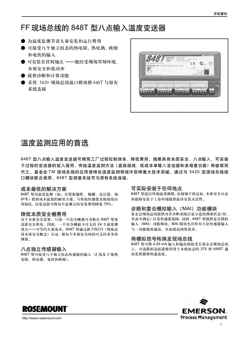
智能无线提供创新无线温度测量解决方案
• 自组网络提供可靠性高达 >99% 的丰富数据,且极其 稳定
• IEC 认证 WirelessHART® 协议 • 艾默生 SmartPower™ 方案提供本质安全电源模块,
支持现场更换,不需要从过程设备上拆卸变送器,从而 确保人员安全并节省维护费用 • 艾默生过程管理的多层无线网络安全方案可确保数据 传输的安全性
线路滤波器
标准
F5
50 Hz 线路电压滤波器
校准证书
标准
Q4
校准证书 (3 点校准)
舰载认证
标准
SBS
美国验船局 (ABS) 认证
SLL
劳氏船级社 (LR) 认证
特殊温度测试
扩展型
LT
测试至 –51.1 °C (–60 °F)
导管电气连接器
罗斯蒙特248温度变送器选型中文样本

248
!
!
!" !"# $ 4 !"#$%& ' !"#$ !"#$ 0 !"#$%&'
!
!"#$%& 5
!"
!
0.5 !"#$%&'( ! HART !"# !"#$
2
4-20 mA ! 4-20 mA !"
!" C1 !"
!"#$#%&
! "#$%&'()*+, !"#$ HART !"#$%
1/2
NPT K N
!"#$%
!l 18 AWG 8 mm
18 SWG 16 AWG ! "J !"PTFE
K
! " 19 SWG !"#$ 0. !"# IEC 584
! 500 V dc
!
!/ !"#$ !"# / / 760 C ! 0 0 1150 C 32 1400 F 32 2102 F 1.1 C 1.1 C 0.4% ! 0.4% ! !"# !"# ! ! 304 SST
0.2
C !"#$%&'(
!"#$%&'() -40 85 C -40 185 F. !"#$%&'() Pt 100 a = 0.00385 !"# 0-100 C !" 0.006 C x 30 - 20 = 0.06 C !"#$%&'( !"#$%&:
罗斯蒙特 248 变送器和温度监测装配件 快速说明书
罗斯蒙特 248 变送器和温度监测装配件开始安全仪表系统启动变送器检查过程连接件确认组态回路测试结束HART®¢00825-0100-482© 2006 罗斯蒙特股份有限公司版权所有。
保留所有权利。
商标所有人享有商标的一切财产权利。
该安装指南为罗斯蒙特® 248 提供基本指导原则。
但并不提供详细的组态、诊断、维护、维修、故障检修或安装指南。
欲了解更多指南,请参阅罗斯蒙特 248 参考手册(文件编号00809-0106-4825)。
欲浏览电子版参考手册和快速安装指南(QIG),请访问网站: 。
爆炸可导致死亡或重伤:在易爆环境中安装本变送器必须符合当地、国内和国际适用的标准、规范与规程。
与安装安全相关的限制条件,请参阅危险场所认证。
在隔爆/防燃环境安装时,在装置通电情况下严禁拆除变送器的封盖。
过程泄漏可引起受伤甚至导致死亡•在施加压力前安装并拧紧热电偶套管或传感器。
•在运行过程中严禁拆除热电偶套管。
电击可导致死亡或重伤•应尽量避免与引线和端子接触。
引线上可能存在的高压可导致电击事故。
Emerson Process Management Rosemount Inc.8200 Market Boulevard Chanhassen, MN USA 55317T (US) (800) 999-9307T (Intnl) (952) 906-8888F (952) 949-7001Emerson Process Management Shared Services Ltd.Heath PlaceWest Sussex PO22 9SH EnglandT 44 (1243) 863 121F 44 (1243) 867 554Emerson ProcessManagement Asia Pacific Private Limited1 Pandan Crescent Singapore 128461T (65) 6777 8211F (65) 6777 0947Enquiries@AP 第一步:组态(工作台标定)罗斯蒙特 248 采用 375 现场通信器进行通信(通信要求回路电阻介于 250 至 1100 Ohm 之间。
艾默生 Rosemount 248 温度变送器 数据表

产品说明书00813-0106-4248, Rev GE2022 年 9 月Rosemount™ 248 无线温度变送器■温度变送器提供无线过程监控解决方案。
■凭借经业界实践检验的能力和技术规格优化工厂效率,提高测量可靠性■艾默生无线技术可以提供创新性的无线温度测量与变送器总体性能方案■研究艾默生 Complete Point Solutions™的优势功能和优点标准温度变送器提供高成本效益的无线过程监控解决方案■具有支持通用传感器输入(RTD、T/C、mV 和 ohms)的单传感器的能力■IEC 认证Wireless HART®协议■大 LCD 显示屏凭借经业界实践检验的能力和技术规格优化工厂效率,提高测量可靠性■一年稳定性保证,可节省维护费用■以用户为中心的设备仪表板传送重要的诊断信息,确保过程健康性■开路/短路传感器诊断功能有助于检测传感器回路的问题■环境温度补偿能力提高变送器的性能■拥有四种可由用户组态的警报,提高用户对过程信息和测量点的洞察力无线技术可以提供创新性的无线温度测量与变送器总体性能方案■自组网络提供数据可靠性高达 99% 以上的丰富数据,并产生极其稳定的网络■智能无线功能可以把 Plantweb™的全部优点延伸到以前难以到达的温度测量地点■艾默生 SmartPower™解决方案提供本安电源模块,支持现场更换,不需要从工艺管道上拆卸变送器,从而确保人员安全并节省维护费用■艾默生的多层无线网络安全方案可确保数据传输的安全性内容功能和优点 (2)订购信息 (4)技术规格 (8)产品认证 (14)尺寸图 (18)Rosemount 248 无线2022 年 9 月研究整套罗斯蒙特温度测量解决方案的优点■艾默生提供一系列热电阻、热电偶和热套管,为温度感知领域带来了优异的耐用性和罗斯蒙特的可靠性,形成完整的罗斯蒙特变送器产品组合。
体验全球一致性以及由众多的全球罗斯蒙特温度测量产品制造点提供的本地支持■经验丰富的仪表顾问可帮助您为任何温度应用选择正确的产品,并提供最佳安装做法的建议■广泛的全球艾默生服务与支持人员网络能够在任何时间、任何地点提供现场服务■凭借全球制造,从各家工厂提供全球一致的产品以及满足任何规模的工程需求的能力使用资产位号随时获取信息新发运设备包含一个唯一的二维码资产位号,您可以通过它直接从设备访问序列化信息。
罗斯蒙特变送器运用以及选型

<br />
我们感到罗斯蒙特公司的AMS管理系统也是一个非常好的有创新的管理软件。投资不多,但能明显提高我们的工作效率和管理水平。符合现代化工厂的管理要求。所以我们也在二期工程中定购了一套单点AMS系统进行使用。不久就可以投入使用。</P>
<p> <wbr></P>
<p>
现在生产变送器的公司有很多。随着科学技术的进步。变送器之间的差别也在缩小。各个公司都把自己的产品宣传的比较好。产品样本提供的数据也多比较高,但我们的体会是:<br />
<br />
a.AMS管理系统可以对工厂使用的智能变送器建立一个完整的数据库。能随时记录这些变送器的全部特性、量程、材质、维修的更改。使用户能更方便、全面地管理这些设备。大大简化以前对变送器的管理工作量。并可以最大程度地减少人为差错。保证生产的稳定。<br />
<br />
b.在线的AMS管理系统可以让操作工程师在控制室内对在装置上的变送器进行实时的组态,诊断和调试。如果连在系统上的任何一台变送器出现问题。AMS管理系统能马上给于警告。指明故障所在。大大减少了判断故障所需的时间。便于维修人员能马上进行处理。保证生产的稳定。---------<br />
罗斯蒙特848T温度变送器选型中文样本
85
C
-40
185
F
!"#
C
1.8
F ! C
!"# !" = 0.00385 = 0.003916 Ni 120 0.003 0.003 0.003 0.004 0.03 C C C C C C CCC+
1 0.0054 0.0054 0.0054 0.0072 0.054 F R 0.0025% R - 300 0.011% R - 100 0.00043% R 0.00029% R 0.0025% |R| 0.00054% R 0.0025% |R| 0.00036% R R 0.0036% R 0.0043% |R| R R R 300 100 F F F F
7.5-11.9 mm !" 1/2 NPT
!"
!"#$% !" T1 !"#$ !"#$%!"&'()*+*,-./0-123 ! !"# 848T !"# $%& !ASME B 16.5 ANSI /IEEE C62.41-1991 IEEE 587 ! A2 B3 6 kV / 3 kA 1.2 x 50 S 8 x 20 S ! 6 kV / 0.5 kA 100 kHz ! 4 kV EFT 5 x 50 nS !"#$%
!"#$%&
!"#$%&'()*+,-./012345 !"# !"#$% 848T !"#$ MAI !"MAI !"#$%&'()* !"#$%& !"#$%&
罗斯蒙特 248温度变送器HART菜单

low alarm
high alarm
low sat修改报警输出
high sat修改报警输出
Hart output
polladdr
num req preams
burst mode
burst option
device information
tag
date 出厂日期
message
2.诊断与服务diag/service
1.测试/状况test device
loop test 回路测试
自诊断self test
master reset
status
micro board
A/D ASIC
operation
summary byte
sensor info
2.校验calibration
3.写保护 write protect
termnl units
termnl damp
termnl lsl -60度
termnl usl 100度
Dev output config
pv range values
pv lrv 0度
pv urv 200度
pv damp 阻尼
pv unit
pv lsl
pv usl
pv min span
alarm /saturation
lor min trim limt
lor max trim limt
upr min trim limt
upr maxtrim limt
snsr 1 lor trim sat
snsr 1 upr trim sat
terminal temp
Rosemount 248头部安装温度变送器快速安装指南说明书

快速安装指南00825-0206-4825, Rev CA2020 年 5 月Rosemount™ 248 头部安装温度变送器快速安装指南2020 年 5 月安全信息本指南提供 Rosemount 248 头部安装温度变送器的基本安装指导,但不提供组态、诊断、维护、检修、故障排除或安装的详细说明。
请参阅《Rosemount 248 温度变送器参考手册》获取更多说明。
手册和本指南的电子版本亦可以从/Rosemount获得。
警告爆炸爆炸可能会导致死亡或严重受伤。
在有爆炸危险的环境中安装本设备时,请务必遵守适用的当地、国家和国际标准、规范和规程。
请核对危险场所认证中是否有与安全安装相关的任何限制。
警告过程泄漏过程泄漏可能导致死亡或严重受伤。
在加压之前,应安装并拧紧热电偶套管和传感器。
在使用过程中不得拆卸热套管。
警告电力停供触电可能导致死亡或严重受伤。
不得接触引线或接线端子。
引线上可能存在的高压会导致触电。
除非另外标明,否则外壳中的导线管/电缆入口采用½–14 NPT 螺纹牙型。
标有“M20”的入口为M20 × 1.5 螺纹牙形。
在具有多个导线管入口的装置上,所有入口都采用相同的螺纹牙形。
在封闭这些入口时,只能使用具有相容螺纹牙形的堵头、接头、密封接头或导线管。
当在危险场所安装时,在电缆/导线管入口中仅使用已列出或通过 Ex 认证的适当堵头、密封套或接头。
警告物理接触未经授权的人员可能会对最终用户的设备造成明显受损和/或误组态。
这可能是有意或无意的,需要采取相应的防护措施。
物理安全措施是任何安全计划的重要部分,是保护您的系统的基础。
限制未经授权人员进行物理接触,以保护最终用户的资产。
这对于设施中使用的所有系统均是如此。
22020 年 5 月快速安装指南内容组态 (5)安装变送器 (7)接线 (11)执行回路测试 (16)认证安装 (17)产品认证 (18)快速安装指南3快速安装指南2020 年 5 月41组态1.1工作台标定有三种方式组态变送器:•现场通讯器•Rosemount 248 PC 编程工具包•在工厂中使用 C1 选项代码进行自定义有关更多信息,请参阅 Rosemount 248参考手册和现场手持通讯器用户指南。
罗斯蒙特温度仪表手册

NOTICE
Read this manual before working with the product. For personal and system safety, and for optimum product performance, make sure to thoroughly understand the contents before installing, using, or maintaining this product. The United States has two toll-free assistance numbers and one international number: Customer Central 1-800-999-9307 (7:00 a.m. to 7:00 p.m. CST) National Response Center 1-800-654-7768 (24 hours a day) Equipment service needs International 1-952-906-8888
v
Reference Manual
00809-0100-4148, Rev BB
vi
Reference Manual
00809-0100-4148, Rev BB
TableContents
1Section 1: Introduction
1.1 Safety messages . . . . . . . . . . . . . . . . . . . . . . . . . . . . . . . . . . . . . . . . . . . . . . . . . . . . . . . . 1 1.1.1 Warnings . . . . . . . . . . . . . . . . . . . . . . . . . . . . . . . . . . . . . . . . . . . . . . . . . . . . . . . . 1 1.2 Overview . . . . . . . . . . . . . . . . . . . . . . . . . . . . . . . . . . . . . . . . . . . . . . . . . . . . . . . . . . . . . . 2 1.2.1 Manual . . . . . . . . . . . . . . . . . . . . . . . . . . . . . . . . . . . . . . . . . . . . . . . . . . . . . . . . . . 2 1.2.2 Transmitter . . . . . . . . . . . . . . . . . . . . . . . . . . . . . . . . . . . . . . . . . . . . . . . . . . . . . . 2 1.3 Considerations . . . . . . . . . . . . . . . . . . . . . . . . . . . . . . . . . . . . . . . . . . . . . . . . . . . . . . . . . 3 1.3.1 General . . . . . . . . . . . . . . . . . . . . . . . . . . . . . . . . . . . . . . . . . . . . . . . . . . . . . . . . . . 3 1.3.2 Mechanical . . . . . . . . . . . . . . . . . . . . . . . . . . . . . . . . . . . . . . . . . . . . . . . . . . . . . . . 3 1.3.3 Electrical . . . . . . . . . . . . . . . . . . . . . . . . . . . . . . . . . . . . . . . . . . . . . . . . . . . . . . . . . 3 1.3.4 Environmental . . . . . . . . . . . . . . . . . . . . . . . . . . . . . . . . . . . . . . . . . . . . . . . . . . . . 3 1.4 Return of materials . . . . . . . . . . . . . . . . . . . . . . . . . . . . . . . . . . . . . . . . . . . . . . . . . . . . . 5 1.5 Product Recycling/Disposal . . . . . . . . . . . . . . . . . . . . . . . . . . . . . . . . . . . . . . . . . . . . . . 5
罗斯蒙特公司温度测量产品

简介
1.3 传感器漂移报警
3144/3244MV智能型温度变送器是罗斯蒙特公司温度 系列仪表高性能产品的发展。3144型是单一传感器输入的 变送器,3244MV 型可同时接收两个传感器输入。
变送器采用专用集成电路数字技术,以实现最好的精 度和信号一致性。每台变送器均在工厂进行环境温度特性 化,从而保证在很宽的工作温度范围内,变送器精度最高, 漂移最小。
三、全面解决方案 罗斯蒙特公司不仅有全系列的高精度、高可靠性、高稳定性的温度变送器和温度传感器,还
有各种温度测量的应用经验和方案,可为用户的温度测量提供一个全面解决方案。
2
3144 和 3244MV 型智能温度变送器
罗斯蒙特公司
3244MV 型具有多参数测量能力, 一台变送器可实现多种先进测量
· 传感器漂移报警,可预测传感器故障新!
1997年,罗斯蒙特公司收购了德国Hereaus公司,Hereaus公司有100年生产温度传感器的 经验,他的加入大大加强了罗斯蒙特公司在温度测量领域的实力,以实现为用户提供温度测量的 全面解决方案。
我们的主要应用行业包括:化工,石化,石油 &天然气,冶金,电力(包括核电),造纸, 制药,机械制造,食品及饮料,玻璃,水泥,陶瓷,塑料 &橡胶等。
两种变送器均易于在现场安装,既可与温度传感器组 件一体化安装,也可远离传感器安装。坚固的外壳带有全 球通用的导线管连接口,双室结构的铝外壳或不锈钢外壳 已取得危险场所认证。
3244MV型变送器独特的传感器漂移报警功能可帮助 预测传感器故障,该功能适用于如使用双测量元件传感器 测量同一过程温度时。当传感器正常工作时,两个测量元 件间的温差应近似为零。将变送器设置为传感器漂移报警 模式,设定传感器1与传感器2允许的最大温差(漂移量), 当变送器检测到的温差大于该设定最大值时,变送器会输 出一个报警信号,或传送给HART275手操器,AMS或采 用HART协议主机通讯。一条报警信息将显示在表头上。
罗斯蒙特248温度变送器手册
1. 把变送器固定到适当的轨道或面板上。 2. 把热套管安装到管道或工艺容器的壁上。在加压之前,应安装并拧紧热套管。 3. 连接必要的加长接嘴和适配器。使用硅胶带密封接嘴和适配器螺纹。 4. 把传感器拧入热套管中。如果出于恶劣环境的考虑或为了满足规范要求,可安装排放密
封件。 5. 把连接头拧到传感器上。 6. 把传感器引线连接到连接头的端子上。 7. 把附加的传感器引线从连接头连接到变送器上。 8. 安装并拧紧连接头盖。壳盖必须完全结合紧密,以满足防爆要求。 9. 把传感器引线和电源线连接到变送器上。应避免接触引线和端子。
8
快速安装指南
00825-0106-4825, DB 版 2011 年 2 月
罗斯蒙特 248
第 2 步 (续 ...)
轨道安装型变送器 螺纹式传感器连接头 螺纹式传感器
标准加长件 螺纹式热电偶套管
第 3 步:软件安装 (仅适用于 248C)
1. 安装 248C 软件 • 把 248C 的 CD-ROM 放入光驱中 • 从 Windows NT、 2000 或 XP 运行 setup.exe
第 4 步:接线
• 接线图在变送器的顶部标签上。 • 变送器需要外部电源才能工作。 • 变送器电源端子间所需的电压是 12 到 42.4 Vdc (电源端子的额定电压是 42.4 Vdc)。
描述符
1, 3, 4, 3
设备信息
1, 3, 4
设备输出配置
1, 3, 3
诊断与检修 滤波 50/60 Hz 硬件版本
1, 2 1, 3, 5, 1 1, 4, 1
Hart 输出 间断性检测
1, 3, 3, 3 1, 3, 5, 4
回路测试 LRV (范围下限值) LSL (传感器下限值) 测量滤波
罗斯蒙特差压液位选型样本

其他信息 规格:第 36 页 认证:第 45 页 尺寸图示:第 53 页
表 1。 罗斯蒙特 3051L 液位变送器订购信息
带★的标准选项为最常用的选项。为了缩短交货期,请选择带星号 ( ★ ) 的选项。 __ 扩展型选项会延长交货期。
甘油和水
1.13
Neobee M-20
0.92
丙二醇和水混合液 1.02
-75 至 145°C (-102 至 293°F) 0 至 205°C (32 至 401°F) -45 至 205°C (-49 至 401°F) -45 至 160°C (-49 至 320°F)
-15 至 95°C (5 至 203°F) -15 至 205°C (5 至 401°F) -15 至 95°C (5 至 203°F)
订 购 液 位 变 送 器 时,您 也 可 额 外 订 购 一 个 1199 远 程 密 封 件,以 组 成 Tuned-System 组件。与传统的对称式系统(平衡)组件相比,Tuned-System 组件性能有所提高,而安装成本有所下降。
产品特性和功能包括:
• 各种过程连接件
• 对整个变送器 / 密封组件提供量化的性能报告 (QZ 选项)
• 毛细管内径尺寸:0.7 毫米 (0.03 英寸)、 1.1 毫 米 (0.04 英寸)及 1.75 毫米 (0.07 英寸)
• 可维修的焊接式结构性能卓越,坚固耐用,适用于 绝大多数应用
• 全焊接式结构适用于高温和高真空应用 (低于 6 psi-a 或 414 mbar-a)
• 热优化器结构适用于过程温度高以及环境温度低 的应用
为什么使用膜片密封件?
H248 说明书

1H248温度变送器圆卡使用说明书一、概述H248温度变送器圆卡符合HART®协议。
用户能够利用HART®通信管理器对其进行检测和组态。
本手册包括H248技术指标以及使用C100A组态软件标定H248温度变送器圆卡的方法等。
用户在使用H248前,请认真阅读本手册,并按本手册提供的操作方法完成您的操作。
二、温变圆卡主要特点2.1接口特性与技术参数·可通过手持器和PC机组态调试软件远程管理。
· 4~20mA输出叠加HART®协议数字通信(两线制)。
·通信符合HART®协议标准。
· HART通信不影响4~20mA的模拟输出。
· HART变送器供电电压:12V~45V DC。
·输入输出隔离:隔离电压为500V AC。
· A/D数字精度:不同传感器对应的数字精度不同RTD为±0.1℃;E为±0.2℃、J为±0.25℃、K为±0.25℃、N为±0.40℃、R为±0.60℃、T为±0.25℃,S为±0.5℃,B为±0.75℃。
· D/A输出精度:±0.1%F.S。
·参比条件下总的模拟精度= A/D数字精度+ D/A输出精度(热电偶输入式还要加上冷端补偿所带来的±0.25℃的附加误差)·阻尼:0~32秒可调·工作环境温度:-40℃~+85℃2.2信号描述与接口定义2.2.1 HART通信输出波形图2-1 HART通信波形图2.2.2 连接端子定义1234-+电源接线端子图2-2 温度变送器圆卡接线端子2 H248注: “+”和“-”分别为外接电源的正极和负极;1、2、3、4为用于外接传感器的四个接线端子。
对于传感器为热电偶或热电阻及选择不同的接线方式时的接线方法如图2-3所示:图2-3传感器接线示意图注:在传感器为热电偶时,接线端子2接热电偶的正端,接线端子3接热电偶的负端。
罗斯蒙特248温度变送器尺寸图

K
K
L
***
3RD ANGLE SIZE
L
D
3/2 AD
SCALE
REV
CUSTOMER DWG NO. P.O. No. S.O. No. PROJECT NAME DO NOT SCALE PRINT
*** *** TITLE *** *** APP'D
DR.
M
FORM REV AA
ROSEMOUNT 248 TEMPERATURE TRANSMITTER
JLA JR 3/15/13 DRAWING NO. 3/15/13 - DOC TYPE SHEET
M
CAD MAINTAINED, (PRO/E) PRODUCT CODE
1
2
3
4
5
6
7
8
9
10
11
12
13
14
REVISION AD CONVERT TO PRO/E
15 REVISION TABLE
ECO NO. RTC1056505 DESCRIPTION APP'D JR
16
DATE 3/15/13
A
ROSEMOUNT 248 TEMPERATURE TRANSMITTER CONNECTION HEAD ENCLOSURE
UNLESS OTHERWISE SPECIFIED DIMENSIONS IN INCHES [mm].
TAG NO.
J
J
K
K
L
***
3RD ANGLE SIZE
248、644和3144温度快速接线

众所周知,罗斯蒙特是以温度起家的,基本温度变送器为温度测量点提供可靠的解决方案,尤其是推出的248、644和3144系列温度,深受广大客户的喜爱。
下面就给大家介绍这三款温度变送器的接线方式。
一、248可分为248H顶部安装型及248R导轨安装型变送器1、248H顶部安装型变送器由上图可看到248带外壳的变送器,模块中分为二个区域,电源区及接线区,*电源区外接24V电源;*传感器接线区接线方式具体如下(看连接图):红线接正极,白线接负级→2线制:红线接2(1、2串联),白线接3(3、4串联);→3线制:红线接2(1、2串联),白线接3、4;→4线制:红线接1、2,白线接3、4注意:串联情况仅为变送器未设置线制的情况,若客户所需线制与变送器线制一致,则无需串联。
2、248R导轨安装型变送器248R导轨型接线方式和248H顶部安装型一样,248温度变送器均为单传感器输入类型,此系列均不带显示。
二、644可分为单传感器输入(644H和644R)和双传感器输入类型644S1、单传感器输入644H由上图可看到644带外壳的变送器,模块中分为三个区域,电源区、报警开关及传感器接线区;*电源区外接24V电源;*报警开关:H和L表示故障模式,H表示高,L表示低;*单传感器接线区接线方式具体如下(看连接图):红线接正极,白线接负级→2线制:红接3(3、4串联),白接2(1、2串联);→3线制:红接3(3、4串联),白接1、2;→4线制:红接3、4,白接1、2注意:串联情况仅为变送器未设置线制的情况,若客户所需线制与变送器线制一致,则无需串联。
2、双传感器输入644S,双热电偶要特别注意正负极接线要正确,接线图如下:3、644R导轨式:接线图如下:三、3144P温度变送器可分为单传感器输入和双传感器输入1、3144P温度变送器单传感器输入2、3144P温度变送器双传感器输入注意事项:1、串联情况仅为变送器未设置线制的情况,若客户所需线制与变送器线制一致,则无需串联。
Rosemount 248 铁轨安装温度变送器 (RK 选项和 HART

Quick Start Guide00825-0300-4825, Rev BAJune 2022 Rosemount™ 248 Rail Mount Temperature Transmitterwith RK Option and HART® 7 ProtocolQuick Start Guide June 2022 ContentsAbout this guide (3)Installation (5)Configuration (8)Mount the transmitter (10)Product certifications (12)China RoHS (25)/RosemountJune 2022Quick Start Guide1About this guideThis guide provides basic guidelines to install the Rosemount 248R RailMount Temperature Transmitter. It does not provide instructions fordetailed configuration, diagnostics, maintenance, service, troubleshooting,or installations. Refer to the Rosemount 248R Temperature TransmitterReference Manual for more instruction. The manual and this guide are alsoavailable electronically at /Rosemount.1.1Safety messagesWARNINGExplosionsExplosions could result in death or serious injury.Installation of device in an explosive environment must be in accordancewith appropriate local, national, and international standards, codes, andpractices.Review the Hazardous Locations Certifications for any restrictionsassociated with a safe installation.Process leaksProcess leaks could result in death or serious injury.Install and tighten thermowells and sensors before applying pressure.Do not remove the thermowell while in operation.Electrical shockElectrical shock could cause death or serious injury.Avoid contact with the leads and terminals. High voltage that may bepresent on leads can cause electrical shock.Unless marked, the conduit/cable entries in the housing use a ½–14 NPTthread form. Entries marked “M20” are M20 × 1.5 thread form. Ondevices with multiple conduit entries, all entries will have the samethread form. Only use plugs, adapters, glands, or conduit with acompatible thread form when closing these entries.When installing in a hazardous location, use only appropriately listed orEx certified plugs, glands, or adapters in cable/conduit entries.Quick Start Guide3Quick Start Guide June 2022 WARNINGPhysical accessUnauthorized personnel may potentially cause significant damage to and/ormisconfiguration of end users’ equipment. This could be intentional orunintentional and needs to be protected against.Physical security is an important part of any security program andfundamental to protecting your system. Restrict physical access byunauthorized personnel to protect end users’ assets. This is true for allsystems used within the facility./RosemountJune 2022Quick Start Guide 2Installation2.1Safety messagesInstructions and procedures in this section may require special precautionsto ensure the safety of the personnel performing the operations.Information that potentially raises safety issues is indicated by a warningsymbol (). Please refer to the following safety messages before performingan operation preceded by this symbol.WARNINGFailure to follow these installation guidelines could result in death orserious injury.Ensure only qualified personnel perform the installation.Explosions could result in death or serious injury.Do not remove the housing covers in explosive atmospheres when thecircuit is live.Before connecting a handheld communicator in an explosiveatmosphere, ensure the instruments are installed in accordance withintrinsically safe or non-incendive field wiring practices.Verify that the operating atmosphere of the transmitter is consistentwith the appropriate hazardous locations certifications.All connection head covers must be fully engaged to meet explosion-proof requirements.Process leaks could result in death or serious injury.Do not remove the thermowell while in operation.Install and tighten thermowells and sensors before applying pressure.Electrical shock could cause death or serious injury.Use extreme caution when making contact with the leads and terminals. Quick Start Guide5Quick Start Guide June 20222.2ConnectionsSingle input(1)When using thermocouple input, the transmitter can be configured for eitherconstant, internal or external CJC via a Pt100 or Ni100 sensor. This must beselected during device configuration.2.3Multidrop modeThe communication is either by means of a HART® communicator or a HARTmodem.The HART communicator or a HART modem can be connected across BC orCD.The outputs of maximum 63 transmitters can be connected in parallel for adigital HART 2-wire communication.Before it is connected, each transmitter must be configured with a uniquenumber from 1 to 63. If two transmitters are configured with the samenumber, both will be excluded. The transmitters must be programmed formultidrop mode (with a fixed output signal of 4 mA). Maximum current inthe loop is therefore 252 mA./RosemountJune 2022Quick Start GuideA.Power supplyB.ConnectionC.ConnectionD.ConnectionE.250 Ω < R load < 1100 ΩF.TransmitterQuick Start Guide7Quick Start Guide June 2022 3Configuration3.1Safety messagesInstructions and procedures in this section may require special precautionsto ensure the safety of the personnel performing the operations.Information that potentially raises safety issues is indicated by a warningsymbol (). Please refer to the following safety messages before performingan operation preceded by this symbol.WARNINGFailure to follow these installation guidelines could result in death orserious injury.Ensure only qualified personnel perform the installation.Explosions could result in death or serious injury.Do not remove the housing covers in explosive atmospheres when thecircuit is live.Before connecting a handheld communicator in an explosiveatmosphere, ensure the instruments are installed in accordance withintrinsically safe or non-incendive field wiring practices.Verify that the operating atmosphere of the transmitter is consistentwith the appropriate hazardous locations certifications.All connection head covers must be fully engaged to meet explosion-proof requirements.Process leaks could result in death or serious injury.Do not remove the thermowell while in operation.Install and tighten thermowells and sensors before applying pressure.Electrical shock could cause death or serious injury.Use extreme caution when making contact with the leads and terminals. 3.2Configuration methodsThe device can be configured in the following ways:•With a HART® communicator with Emerson's DDL driver•Via programming framework (e.g. AMS Device Manager, DCS,PACTware™)/RosemountJune 2022Quick Start GuideHART communicatorTo get access to product-specific commands, the HART communicator mustbe loaded with Emerson's DDL driver. This can be ordered through either theFieldComm Group or Emerson.A.Rosemount transmitterB.Ex areaC.Safe areaD.250 Ω < R load < 1100 ΩE.Receiving equipmentF.+V supplyG.InputProgramming frameworkSupport for both EDD and FDT®/DTM™ technology, offering configurationand monitoring via relevant DCS/Asset Management Systems andsupported management packages (e.g. PACTware).A DA.Rosemount transmitterB.250 Ω < R load < 1100 ΩC.Process computerD.DCS, etc.Quick Start Guide9Quick Start Guide June 2022 4Mount the transmitter4.1Rail mount transmitter with remote mount sensorThe least complicated assembly uses:• a remote mounted transmitter•an integral mount sensor with terminal block•an integral style connection head• a standard extension• a threaded thermowellRefer to the Metric Sensor Product Data Sheet for complete sensor andmounting accessory information.4.1.1Assemble the deviceTo complete the assembly:Procedure1.Attach the transmitter to a suitable rail or panel.2.Attach the thermowell to the pipe or process container wall. Installand tighten the thermowell before applying pressure.3.Attach the sensor to the connection head and mount the entireassembly to the thermowell.4.Attach sufficient lengths of sensor lead wire to the sensor terminalblock.5.Attach and tighten the connection head cover. Enclosure coversmust be fully engaged to meet explosion-proof requirements.6.Run sensor lead wires from the sensor assembly to the transmitter.7.Attach the sensor and power leads to the transmitter. Avoid contactwith leads and terminals.4.2Rail mount transmitter with threaded sensorThe least complicated assembly uses:• a threaded sensor with flying heads• a threaded sensor connection head• a union and nipple extension assembly• a threaded thermowell/RosemountRefer to Rosemount Metric Sensor Product Data Sheet for complete sensorand mounting accessory information.4.2.1Assemble the deviceTo complete the assembly:Procedure1.Attach the transmitter to a suitable rail or panel.2.Attach the thermowell to the pipe or process container wall. Installand tighten the thermowell before applying pressure.3.Attach necessary extension nipples and adapters. Seal the nipple andadapter threads with silicone tape.4.Twist the sensor into the thermowell. Install drain seals if required forsevere environments or to satisfy code requirements.5.Screw the connection head to the sensor.6.Attach the sensor lead wires to the connection head terminals.7.Attach additional sensor lead wires from the connection head to thetransmitter.8.Attach and tighten the connection head cover. Enclosure coversmust be fully engaged to meet explosion-proof requirements.9.Attach the sensor and power leads to the transmitter. Avoid contactwith leads and terminals.5Product certificationsRev: 1.15.1European Directive informationA copy of the EU Declaration of Conformity can be found at the end of theQuick Start Guide. The most recent revision of the EU Declaration ofConformity can be found at /Rosemount.5.2Ordinary location certificationAs standard, the transmitter has been examined and tested to determinethat the design meets the basic electrical, mechanical, and fire protectionrequirements by a nationally recognized test laboratory (NRTL) as accreditedby the Federal Occupational Safety and Health Administration (OSHA). 5.3Installing equipment in North AmericaThe US National Electrical Code® (NEC) and the Canadian Electrical Code(CEC) permit the use of Division marked equipment in Zones and Zonemarked equipment in Divisions. The markings must be suitable for the areaclassification, gas, and temperature class. This information is clearly definedin the respective codes.5.4USA5.4.1I5 USA Intrinsically Safe (IS) and Division 2/Zone 2Certificate80072530Standards UL Std No 913 Ed. 8, UL 60079-0 Ed. 5, UL 60079-11 Ed. 6, UL60079-15 Ed. 4, UL 61010-1 Ed. 3Markings Class I, Division 1, Groups A, B, C, DClass I, Zone 0: AEx ia IIC T6…T4Class I, Zone 1: AEx ib [ia] IIC T6…T4Class I, Division 2, Groups A, B, C, DClass I, Zone 2: AEx nA IIC T6…T4Class I, Zone 2: AEx nA [ic] IIC T6…T4when installed per Control Drawing 00248-8000Table 5-1: IS Input Parameters vs Temperature RangeTable 5-2: IS Output Parameters per Terminal ConfigurationTable 5-3: Division 2/Zone 2 Input Parameters vs Temperature RangeSpecial Conditions for Safe Use (X):1.Install per Installation Drawing 00248-8000 as appropriate.2.Install in accordance with the US National Electrical Code (NEC) forthe US and in accordance with the Canadian Electrical Code (CEC) for Canada.3.The transmitter must be installed in suitable enclosure to meetinstallation codes stipulated in the Canadian Electrical Code (CEC) orfor the US the National Electrical Code (NEC).4.If the enclosure is made of non-metallic materials or of paintedmetal, electrostatic charging shall be avoided.5.For Div 2/Zone 2 applications, the transmitter must be installed in anenclosure providing a degree of protection of at least IP54 accordingto IEC60529 that is suitable for the application and is correctlyinstalled. Cable entry devices and blanking elements shall fulfil thesame requirements.e supply wires with a rating of at least 5 K above the ambienttemperature.7.For Div 2/Zone 2 applications, the temperature transmitter requiresconnecting to Class 2 Power Supply with Transient protection. Seeinstallation drawing as appropriate.5.5Canada5.5.1I6 Canada Intrinsically Safe (IS) and Division 2/Zone 2Certificate:80072530Standards:CSA C22.2 No. 157-92 (R2012), CAN/CSA C22.2 No.60079-0:11, CAN/CSA C22.2 No. 60079-11:11, CAN/CSAC22.2 No. 60079-15:12, CSA 61010-1-12Markings:Class I, Division 1, Groups A, B, C, DEx ia IIC T6…T4Ex ib [ia] IIC T6…T4Class I, Division 2, Groups A, B, C, DEx nA IIC T6…T4Ex nA [ic] IIC T6…T4when installed per Control Drawing 00248-8000Table 5-4: IS Input Parameters vs Temperature RangeTable 5-5: IS Output Parameters per Terminal ConfigurationTable 5-6: Division 2/Zone 2 Input Parameters vs Temperature RangeSpecial Conditions for Safe Use (X):1.Install per Installation Drawing 00248-8000 as appropriate.2.Install in accordance with the US National Electrical Code (NEC) forthe US and in accordance with the Canadian Electrical Code (CEC) for Canada.3.The transmitter must be installed in suitable enclosure to meetinstallation codes stipulated in the Canadian Electrical Code (CEC) orfor the US the National Electrical Code (NEC).4.If the enclosure is made of non-metallic materials or of paintedmetal, electrostatic charging shall be avoided.5.For Div 2/Zone 2 applications, the transmitter must be installed in anenclosure providing a degree of protection of at least IP54 accordingto IEC60529 that is suitable for the application and is correctlyinstalled. Cable entry devices and blanking elements shall fulfil thesame requirements.e supply wires with a rating of at least 5 K above the ambienttemperature.7.For Div 2/Zone 2 applications, the temperature transmitter requiresconnecting to Class 2 Power Supply with Transient protection. Seeinstallation drawing as appropriate.5.6Europe5.6.1I1 ATEX Intrinsic SafetyCertificate:DEKRA 21ATEX0003XStandards:EN60079-0:2012+A11:2013, EN60079-11:2012Markings: II 1 G Ex ia IIC T6…T4 GaII 2(1) G Ex ib [ia Ga] IIC T6…T4 GbII 1 D Ex ia IIIC DaI 1 M Ex ia I Mawhen installed per Control Drawing 00248-8001Special Conditions for Safe Use (X):1.For all potentially explosive atmospheres, if the enclosure is made ofnon-metallic materials, or if it is made of metal having a paint layerthicker than 0.2 mm (group IIC), or 2 mm (group IIB, IIA, I), or anythickness (group III), electrostatic charges shall be avoided.2.For EPL Ga, if the enclosure is made of aluminum, it must be installedsuch that ignition sources due to impact and friction sparks areexcluded.3.For EPL Da, the surface temperature “T” of the enclosure, for a dustlayer with a maximum thickness of 5 mm, is the ambienttemperature +20 K.5.6.2N1 ATEX Zone 2Certificate:DEKRA 21ATEX0004XStandards:EN60079-0:2012+A11:2013, EN60079-7:2015+A1:2018,EN60079-11:2012, EN60079-15:2010Markings: II 3 G Ex nA IIC T6…T4 GcII 3 G Ex ec IIC T6…T4 GcII 3 G Ex ic IIC T6...T4 GcII 3 D Ex ic IIIC Dcwhen installed per Control Drawing 00248-8001Table 5-7: Maximum Output of TransmitterSpecial Conditions for Safe Use (X):1.For all potentially explosive atmospheres, if the enclosure is made ofnon-metallic materials, or if it is made of metal having a paint layerthicker than 0.2mm (group IIC), or 2mm (group IIB, IIA, I), or anythickness (group III), electrostatic charges shall be avoided.2.The transmitter shall be installed in an enclosure providing a degreeof protection of not less than IP54 in accordance with EN 60079-0,which is suitable for the application and correctly installed, e.g. in anenclosure that is in type of protection Ex n or Ex e.3.Additional, for Ex nA or Ex ec, the area inside the enclosure shall bepollution degree 2 or better, as defined in EN 60664-1.4.For EPL Dc, the surface temperature “T” of the enclosure, for a dustlayer with a maximum thickness of 5mm, is the ambient temperature +20K.5.7International5.7.1I7 IECEx Intrinsic SafetyCertificate IECEx DEK 21.0002XStandards IEC 60079-0:2011, IEC 60079-11:2011Markings Ex ia IIC T6…T4 GaEx ib [ia Ga] IIC T6…T4 GbEx ia IIIC DaEx ia I Mawhen installed per Control Drawing 00248-8002Special Conditions for Safe Use (X):1.For all potentially explosive atmospheres, if the enclosure is made ofnon-metallic materials, or if it is made of metal having a paint layerthicker than 0.2 mm (group IIC), or 2 mm (group IIB, IIA, I), or anythickness (group III), electrostatic charges shall be avoided.2.For EPL Ga, if the enclosure is made of aluminum, it must be installedsuch that ignition sources due to impact and friction sparks areexcluded.3.For EPL Da, the surface temperature “T” of the enclosure, for a dustlayer with a maximum thickness of 5 mm, is the ambienttemperature +20 K.5.7.2N7 IECEx Zone 2Certificate:IECEx DEK 21.0002XStandards:IEC 60079-0:2011, IEC 60079-7:2017, IEC 60079-11:2011,IEC 60079-15:2010Markings:Ex nA IIC T6…T4 GcEx ec IIC T6…T4 GcEx ic IIC T6…T4 GcEx ic IIIC Dcwhen installed per Control Drawing 00248-8002June 2022Quick Start Guide Table 5-8: Maximum Output of TransmitterSpecial Conditions for Safe Use (X):1.For all potentially explosive atmospheres, if the enclosure is made ofnon-metallic materials, or if it is made of metal having a paint layerthicker than 0.2mm (group IIC), or 2mm (group IIB, IIA, I), or anythickness (group III), electrostatic charges shall be avoided.2.The transmitter shall be installed in an enclosure providing a degreeof protection of not less than IP54 in accordance with EN 60079-0,which is suitable for the application and correctly installed, e.g. in anenclosure that is in type of protection Ex n or Ex e.3.Additional, for Ex nA or Ex ec, the area inside the enclosure shall bepollution degree 2 or better, as defined in EN 60664-1.4.For EPL Dc, the surface temperature “T” of the enclosure, for a dustlayer with a maximum thickness of 5mm, is the ambient temperature+20K.5.8China5.8.1I3 China (NEPSI) Intrinsic SafetyCertificate GYJ21.1036XStandards GB3836.1-2010, GB3836.4-2010, GB3836.20-2010,GB12476.1-2013, GB12476.4-2010Markings Ex ia IIC T4/T5/T6 GaEx ib [ia Ga] IIC T4/T5/T6 GbEx iaD 20 T80 °C/T95 °C/T130 °CEx ibD [iaD 20]21 T80 °C/T95 °C/T130 °CSpecial Condition for Safe Use (X):See certificate for special conditions.5.8.2N3 China (NEPSI) Zone 2Certificate GYJ21.1036XQuick Start Guide21Quick Start Guide June 2022 Standards GB3836.1-2010, GB3836.4-2010, GB3836.8-2014,GB3836.20-2010Markings Ex nA [ic Gc] IIC T6…T4 GcEx ic IIC T6…T4 GcSpecial Condition for Safe Use (X):See certificate for special conditions./Rosemount5.9Declaration of conformityJune 2022Quick Start GuideQuick Start Guide 23Quick Start Guide June 2022/Rosemount6China RoHSJune 2022Quick Start Guide Quick Start Guide 25Quick Start Guide June 2022 /RosemountJune 2022Quick Start Guide Quick Start Guide27*00825-0300-4825*Quick Start Guide00825-0300-4825, Rev. BAJune 2022For more information: ©2022 Emerson. All rights reserved.Emerson Terms and Conditions of Sale areavailable upon request. The Emerson logois a trademark and service mark ofEmerson Electric Co. Rosemount is a markof one of the Emerson family ofcompanies. All other marks are theproperty of their respective owners.。
罗斯蒙特248温度变送器资料2011中文版

表 2. 248R 顶部安装型变送器
提供的标准选项代表了最常用的选项。打上星号的选项 ( ) 可以得到最佳的交货期。 __ 扩展选项交货期会稍长。
型号 产品说明
248R 导轨安装温度变送器
输出协议
标准
A
4-20mA,带有基于 HART 协议的数字信号
产品认证
标准 I5 I6 I1 NC I7(1) 不适用
标准的变送器设计提供了在过程环境中使用时所需灵活而可靠的性能
• 通过将传感器直接连接到数字控制系统,改善了测量精度和可靠性,从而降低整体安装成本 • 一年的稳定性降低了维护成本 • 传感器的开路 / 短路诊断系统可以帮助检测传感器回路中的问题 • 对环境温度进行补偿,强化了变送器的性能
通过罗斯蒙特温度测量技术,取得了全面单点温度测量解决方案的益处
推荐的最小测量量程
10 K
软件检测故障模式
在故障模式下,变送器强制改动的输出数值取决于其组态形式:标 准、自定义或符合 NAMUR (NAMUR 推荐标准 NE 43)运行。标 准及符合 NAMUR 运行要求的值如表所示:
图 1. 操作参数
标准(1)
NAMUR NE43- 符合
(1)
线性输出: “高”故障:
标准 标准 标准 标准 标准 标准
5
罗斯蒙特 248
变送器技术规格
产品数据表
00813-0100-4825,版本 JA 7 2011
功能规格
输入
可由用户选择;传感器端子额定值为 42.4Vdc。传感器选项见 “变 送器精度和环境温度影响”在第 8 页。
输出
2 线制 4-20 mA, 与温度或输入成线性;与 4-20 mA 信号重叠的数 字输出信号,适用于现场通讯器或控制系统接口。
艾默生 罗斯蒙特 148 型温度变送器 数据表

产品数据表2014年2月00813-0106-4148, FA版⏹基本温度变送器提供经济高效的温度监测点解决方案 ⏹标准变送器设计在过程环境中提供灵活可靠的性能⏹与对传感器直接接线的安装方式相比,本产品可降低总体安装成本,并减少对昂贵的分接线和多工器的需求⏹基于 PC 的 HART 组态界面提供变送器组态所需的编程器、线缆和软件⏹发掘整套罗斯蒙特温度点方案的优点罗斯蒙特 148 型温度变送器罗斯蒙特 148 型2014年2月罗斯蒙特 148 型温度变送器基本温度变送器提供经济高效的温度监测点解决方案⏹DIN B 型头部安装式变送器⏹有多种 DIN B 外壳选项⏹4-20 mA 模拟协议⏹支持通用传感器输入(RTD、T/C、ohms)的单传感器能力⏹基于 PC 的组态标准变送器设计在过程环境中提供灵活可靠的性能⏹与把传感器直接接线至数字控制系统的方法相比,可提高测量精度和可靠性,并降低总体安装成本⏹一年稳定性保证,节省维护费用⏹基于 PC 的组态界面提供变送器组态所需的编程器、线缆和软件⏹环境温度补偿能力提高变送器的性能探究整套罗斯蒙特温度测量点方案的优点⏹通过 “组装至传感器” 选项,艾默生提供全套温度测量点方案,提供可直接安装的变送器和传感器组件⏹艾默生提供一系列 RTD、热电偶和温度计套管,为温度感测领域带来了优异的耐用性和罗斯蒙特的可靠性,形成完整的罗斯蒙特变送器产品组合2014年2月罗斯蒙特 148 型体验全球一致性以及由众多的全球罗斯蒙特温度测量产品制造点提供的本地支持⏹通过全球制造,从每家工厂提供全球一致的产品以及满足任何规模的工程需求的能力⏹经验丰富的仪表顾问可帮助您为任何温度应用选择正确的产品,并提供最佳安装做法的建议⏹广泛的全球艾默生服务与支持人员网络能够在任何时间、任何地点提供现场服务⏹您是否正在寻求以经济高效的方式测量更多温度点?请考虑无线温度解决方案。
罗斯蒙特 248 型无线温度变送器性能稳定,并且经济。
- 1、下载文档前请自行甄别文档内容的完整性,平台不提供额外的编辑、内容补充、找答案等附加服务。
- 2、"仅部分预览"的文档,不可在线预览部分如存在完整性等问题,可反馈申请退款(可完整预览的文档不适用该条件!)。
- 3、如文档侵犯您的权益,请联系客服反馈,我们会尽快为您处理(人工客服工作时间:9:00-18:30)。
0.2
C !"#$%&'(
!"#$%&'() -40 85 C -40 185 F. !"#$%&'() Pt 100 a = 0.00385 !"# 0-100 C !" 0.006 C x 30 - 20 = 0.06 C !"#$%&'( !"#$%&:
!"#$%&
!"#$%&'( C
!"#
+
* 80
3.2
900
!"#
N=
!" U= !"#$% !"#$%&'(
! mm !"#
!
49
248
248
10 DIN !"#$%&'$ mm
!"
! 248H A 4 DIN B ! 20 mA ! !"# I1 E1 N1 NC 1 ND I5 E5 K5 I6 K6 I7 E7 N7 I2 I4 E4 NA A B N !/ 1 2 2 0 !" ZR ZJ ZK XA 3 NS 4 PT 100 J K ! !"#$%&#'()*+,! ! DIN DIN DIN 4 ! ! !IEC !IEC !IEC M20 x 1.5 1/2 NPT !"# BUZ !"#$%DIN IP68 !"DIN IP65 ATEX ATEX ATEX n ATEX n ATEX FM FM FM CSA CSA SAA SAA SAA n CEPEL JIS JIS ! !"# !"# ! !"#$ !"#$ I !"#$ !"# ! !" I 2 !" I 2 !" 2 !" !" !" !" !"#$ I 2 !" !"#$%& !"# ! !"#$ A B N A A N A A B N A A A B N A A B N A A A B N A B N A A B N A= B= C= D= E= !"#$ HART ! ! !"#$%&'()
!"#$%&'()
!"#$
60 Hz 0.21 mm 2000 Hz 3 g
!"
!" U !" !" A ! NEMA 4X IP66 IP68 !" !"#$% 1/2 NPT CSA ! 4X BUZ B IP65 !"
!
!"# !$%&'12 0.1% 0.1 C
!"#$%& !"#$% &
!"#
1/2
NPT K N
!"#$%
!l 18 AWG 8 mm
18 SWG 16 AWG ! "J !"PTFE
K
! " 19 SWG !"#$ 0. !"# IEC 584
! 500 V ቤተ መጻሕፍቲ ባይዱc
!
!/ !"#$ !"# / / 760 C ! 0 0 1150 C 32 1400 F 32 2102 F 1.1 C 1.1 C 0.4% ! 0.4% ! !"# !"# ! ! 304 SST
! rms
/ !" 50/60 Hz 707V dc
500 V ac
!"#$ !"#$%&'()*+,-. !"# NAMUR NAMUR ! NE 43 !" NAMUR !"#$%& ! 1 NAMUR NE43 1 ! 3.9 I 20.5 3.8 I 20.5 21 I 23 ! 21 I 23 I 3.75 I 3.6
! = 0.2
C + 0.06
C = 0.26
C
0.22+0.062=0.21
C
46
!
!"#$
! 10 !"
IEC 584
10 12 11
! 100 V dc
!
!"#$
!"#$% 100
4 DIN ! DIN 1/2 !"#$%&'()*+ IEC 584 CLASS 1 !"#$%&'(#) !"# !"#$%& '()*+,J /
!"#$
248
!"#$%&'()*+,-./0123./ !"#$%&'()*+,. ! !"# 248 DIN ! 13
! -40 ! -58
!
185 248 F -40 85 120 C C
F -50
44
!
!
248 248 U B BUZ A !"#$%&' 42 g 1.5 oz !" 520 g 18.4 oz ! 240 g 8.5 oz !"#$ 524 g 18.5 oz 10 60
248
!
!
!" !"# $ 4 !"#$%& ' !"#$ !"#$ 0 !"#$%&'
!
!"#$%& 5
!"
!
0.5 !"#$%&'( ! HART !"# !"#$
2
4-20 mA ! 4-20 mA !"
!" C1 !"
!"#$#%&
! "#$%&'()*+, !"#$ HART !"#$%
0.1 0.1 0.1 0.1 0.1 0.1 0.1 0.1 0.1 0.1 0.1 0.1 0.1 0.1 0.1 0.1 0.1 0.1 0.1 0.1
Pt 200(2) Pt 500(2) Pt 1000(2) Ni 120(4) Cu 10(5)
(6)
-200 850 -200 850 -200 300 -70 300 -50 250 100 1820 -50 1000 -180 760 -180 1372 -200 1300 0 1768 0 1768 -200 400 -200 900 -200 600 0 2000 -10 100 mV 0 2000
!"#$ !" Q8 !" R01 !"#$%&'()*+, ASME B 16.5 ANSI DIN 2519 2527 2633 2635 DIN 2526 C
!"#$%&'()*+,-./0 85 C !"#$% 40 C !"#$% 540 C !"#$%&'()*+,&'-./0123 !"#$% 85 - 40 45 C 1 C 90 mm 100 mm !" 25 C 150 mm !"#$%& !"#$%&'!() 22 !"#$%& !' !"# !"#$%& !"#$%&'()*+ !"#$%&'()
!
321 SST
!
PTFE 22 !"#$% !" !
!"#$%&
!"#$%& !"#$%& ! ! "#$%&'()*+, !"# !"#$%&'()*+,-./0 !"#$%&' !"#$%&'() !"#$%&'()*+ 1 ! !"#$%&'()*+%,-.,/01 1 !"#$%&'( !"#$ !"#$% 1 !"#$%&'()*)$+,!"#$%&'()*+,!"#$%&' 1 2 3 !"# !"#$%&'()*+,!"#$%&'()*+900 !"#$%&%'( 0.8 m 32 in. CLA.N6 .)/ !"# !"#$
!"# $%
!"#$%& ' !"#$ 1.0 ) !"# !"
(1.8
1
!"#$ ==== c 2 3 4 Pt 100(2) Pt 100(3) ! = 0. 00385 = 0. 003916 -200 -200 850 645 -328 -328 1562 1193 0.2 (0.36 c) 0.2 (0.36 c) 1.17 (2.11 0.47 (0.85 0.23 (0.41 0.16 (0.29 2 (3.60 F) c) c) c) c)
! mA
!"#$%
HART !"#$%& !"#$ !"#$ 12.0 42.4 VDC !" 250 1100 !" !"#$% 17.75 VDC 250 !"# $% 42.4 V DC ! = 40.8 x ! -12.0