立式多级离心泵使用说明书
dl20215;4dl型单级多吸立式离心清水泵型号说明

本信息由三昌水泵厂发布,水泵专业技术团队,二十余年水泵制造经验,优质服务,质量可靠,实力保证,三昌品牌销售,如有需要,可与我厂联系!DL型单级多吸立式离心清水泵单吸立式多级离心泵概述:DL型泵系立式、单吸、多级、分段式离心泵,适用于城镇供水和集中供热系统。
用来输送清水或物理和化学性质类似于清水的液体之用。
DL型泵输送介质温度在80℃以下,DLR型泵输送介质温度在150℃以下。
单吸立式多级离心泵参数范围:流量Q 4.9~200m3/s扬程H 21.6~239m单吸立式多级离心泵型号说明:80DL20×4 80DLR20×480-进水口直径(毫米)20-单级扬程(米)DL-立式多级分段式离心泵DLR-立式多级分段式热水离心泵4-4级单吸立式多级离心泵结构型式:泵为立式安装,具有结构紧凑、噪声低、占地面积小的特点,泵的轴封为填料密封、机械密封。
单吸立式多级离心泵旋转方向:从电机端看,泵为逆时针方向旋转。
单吸立式多级离心泵主要零件材质:泵的过流部件进水段、中段、出水段、叶轮、密封环材质为铸铁,轴为优质碳素钢。
单吸立式多级离心泵成套范围:成套供应泵和电动机。
本信息由三昌水泵厂发布,水泵专业技术团队,二十余年水泵制造经验,优质服务,质量可靠,实力保证,三昌品牌销售,如有需要,可与我厂联系!84参数型号流量Q扬程H转速n轴功率Pa配带电动机效率η必须汽蚀余量叶轮名义直径进出口径泵重功率型号m3/s L/s m r/min kw kw % m mm mm kg40DL-12×2 4.96.27.41.361.722.0624.823.621.614800.8911.121.5 Y90L-4B53740393.19 201404021040DL-12×3 4.96.27.41.361.722.0637.235.432.414801.341.491.672.2 Y100L1-4B53740393.19 201404025040DL-12×4 4.96.27.41.361.722.0649.647.243.214801.791.992.233 Y100L2-4B53740393.19 201404027040DL-12×5 4.96.27.41.361.722.0662595414802.242.492.794 Y112M-4B53740393.19 201404029040DL-12×6 4.96.27.41.361.722.0674.470.864.814802.682.993.354 Y132S-4B53740393.19 201404031040DL-12×7 4.96.27.41.361.722.0686.882.675.614803.133.493.915.5 Y132S-4B53740393.19 201404033540DL-12×8 4.96.27.41.361.722.0699.294.486.414803.583.984.465.5 Y132M-4B53740393.19 201404035540DL-12×9 4.96.27.41.361.722.0611210697.214804.044.475.027.5 Y132M-4B53740393.19 201404037540DL-12×10 4.96.27.41.361.722.0612411810814804.474.985.587.5 Y132M-4B53740393.19 201404039540DL-12×11 4.96.27.41.361.722.0613613011914804.95.496.157.5 Y160M-4B53740393.19 201404041540DL-12×12 4.96.27.41.361.722.0614914213014805.375.996.7211 Y100L2-4B53740393.19 201404044050DL12×2912.616.22.53.54.526.624.421.214801.31.551.83 Y100L2-4B55054522.582.663.16200504023550DL12×3912.616.22.53.54.539.936.631.814801.962.332.73 Y100L2-4B55054522.582.663.16200504025685参数型号流量Q扬程H转速n轴功率Pa配带电动机效率η必须汽蚀余量叶轮名义直径进出口径泵重功率型号m3/s L/s m r/min kw kw % m mm mm kg50DL12×4912.616.22.53.54.553.248.842.414802.613.13.64 Y112M-4B55054522.582.663.16200504028550DL12×5912.616.22.53.54.566.5615314803.263.884.55.5 Y132S-4B55054522.582.663.16200504032650DL12×6912.616.22.53.54.579.873.263.614803.914.655.45.5 Y132S-4B55054522.582.663.16200504034750DL12×7912.616.22.53.54.593.185.474.214804.565.436.37.5 Y132M-4B55054522.582.663.16200504038150DL12×8912.616.22.53.54.5106.497.684.814805.226.27.197.5 Y132M-4B55054522.582.663.16200504040250DL12×9912.616.22.53.54.5119.7109.895.414805.876.988.0911 Y160M-4B55054522.582.663.16200504046850DL12×10912.616.22.53.54.513312210614806.527.758.9911 Y160M-4B55054522.582.663.16200504048965DL-16×2 18303558.339.7237322914803.244.224.615.5 Y132S-4B55662602.412.823.03232655037965DL-16×3 18303558.339.7255.54843.514804.866.336.97.5 Y132M-4B55662602.412.823.03232655044765DL-16×4 18303558.339.7274645814806.488.449.2111 Y160M-4B55662602.412.823.03232655053665DL-16×5 18303558.339.7292.58072.514808.110.611.515 Y160L-4B55662602.412.823.03232655060065DL-16×6 18303558.339.72111968714809.7212.713.815 Y160L-4B55662602.412.823.03232655064465DL-16×7 18303558.339.72130112102148011.414.816.218.5 Y180M-4V15662602.412.823.03232655072886参数型号流量Q扬程H转速n轴功率Pa配带电动机效率η必须汽蚀余量叶轮名义直径进出口径泵重功率型号m3/s L/s m r/min kw kw % m mm mm kg65DL-16×8 18303558.339.7214812811614801316.918.422 Y180L-4V15662602.412.823.03232655079465DL-16×9 18303558.339.72167144131148014.61920.822 Y180L-4V15662602.412.823.03232655083965DL-16×10 18303558.339.72185160145148016.221.12330 Y200L-4V15662602.412.823.03232655096280DL-20×2 32.450.465.1691418.143.24034.214806.287.849.1311 Y160M-4V160.77066.52.162.492.82255806556680DL-20×3 32.450.465.1691418.164.86051.314809.4211.813.715 Y160L-4V160.77066.52.162.492.82255806564080DL-20×4 32.450.465.1691418.186.48068.4148012.615.718.322 Y180L-4V160.77066.52.162.492.82255806575680DL-20×5 50.465.161418.110085.51480 19.622.830 Y200L-4V17066.52.492.82255806590080DL-20×6 32.450.465.1691418.1129.6120102.6148018.823.527.430 Y200L-4V160.77066.52.162.492.82255806594580DL-20×7 32.450.465.1691418.1151140120148021.927.53237 Y225S-4V160.77066.52.162.492.822558065103880DL-20×8 32.450.465.1691418.1173160137148025.131.436.645 Y225M-4V160.77066.52.162.492.822558065112080DL-20×9 32.450.465.1691418.1194180154148028.235.341.445 Y225M-4V160.77066.52.162.492.822558065117580DL-20×10 32.450.465.1691418.1216200171148031.439.245.655 Y250M-4V160.77066.52.162.492.822558065133580DL-30×2 2643487.211.913.36860562980810.110.615 Y160M2-2B560.77066.52.162.492.82162808016787参数型号流量Q扬程H转速n轴功率Pa配带电动机效率η必须汽蚀余量叶轮名义直径进出口径泵重功率型号m3/s L/s m r/min kw kw % m mm mm kg80DL-30×3 2643487.211.913.3102908329801215.115.918.5 Y160L-2B560.77066.52.162.492.82162808019080DL-30×4 2643487.211.913.313612011129801620.121.230 Y200L1-2B560.77066.52.162.492.82162808021480DL-30×5 2643487.211.913.3170150139298020.125.226.530 Y200L1-2B560.77066.52.162.492.82162808023880DL-30×6 2643487.211.913.3204180167298024.130.231.837 Y200L2-2B560.77066.52.162.492.82162808026180DL-30×7 434811.913.32101952980 35.237.145 Y225M-2B57066.52.492.82162808028480DL-30×8 2643487.211.913.3272240222298032.140.242.455 Y250M-2B560.77066.52.162.492.82162808030780DL-30×9 2643487.211.913.3306270250298036.145.347.755 Y250M-2B560.77066.52.162.492.821628080330100DL-20×2 721001262027.83543.44034148013.115.116.722 Y180L-4V16572702.833.534.426710080764100DL-20×3 721001262027.83565.16051148019.622.72530 Y200L-4V16572702.833.534.426710080900100DL-20×4 721001262027.83586.88068148026.230.333.337 Y225S-4V16572702.833.534.426710080995100DL-20×5 721001262027.83510910085148032.937.941.745 Y225M-4V16572702.833.534.4267100801079100DL-20×6 721001262027.835130120102148039.345.45055 Y250M-4V16572702.833.534.4267100801241100DL-20×7 721001262027.835152140119148045.95358.475 Y280S-4V16572702.833.534.426710080144388参数型号流量Q扬程H转速n轴功率Pa配带电动机效率η必须汽蚀余量叶轮名义直径进出口径泵重功率型号m3/s L/s m r/min kw kw % m mm mm kg100DL-20×8 721001262027.835174160136148052.560.566.775 Y250M-4V16572702.833.534.4267100801500100DL-20×9 721001262027.835195180153148058.868.17590 Y280S-4V16572702.833.534.4267100801600100DL-20×10 721001262027.835217200170148065.575.683.390 Y250M-4V16572702.833.534.4267100801657125DL-25×2 12016020033.344.455.6535044148024.128.732.837 Y225S-4V17276733.13.53.8301150125825125DL-25×3 12016020033.344.455.679.57566148036.14349.255 Y250M-4V17276733.13.53.8301150125970125DL-25×4 12016020033.344.455.610610088148048.157.365.775 Y250M-4V17276733.13.53.83011501251110125DL-25×5 12016020033.344.455.6133125110148060.471.782.190 Y280S-4V17276733.13.53.83011501251255125DL-25×6 12016020033.344.455.6159150132148072.28698.5110 Y315S-4V17276733.13.53.83011501251410125DL-25×7 12016020033.344.455.6186175154148084.2100115132 Y315M-4V17276733.13.53.83011501251570125DL-25×8 12016020033.344.455.6212200176148096.2115132132 Y315M-4V17276733.13.53.83011501251880125DL-25×9 12016020033.344.455.62392251981480108129148160 Y315L1-4V17276733.13.53.8301150125。
25LG3-10X4-多层建筑水泵说明书

25LG3-10X4型高层建筑多级给水泵一、产品概述:LG 型高层建筑多级给水泵,系立式单吸多级分段式离心泵,供输送常温清水及物理化学性质类似于清水的液体。
LG 系列泵为立式安装,电机轴与泵轴通过爪型连轴器联接,具有结构紧凑、噪音低、占地面积小等优点。
本司产品全部采用计算机设计和优化处理,公司拥有雄厚的技术力量、丰富的生产经验和完善的检测手段,从而保证产品质量的稳定可靠。
二、适用范围:主要应用于高层建筑供水,也可应用于厂矿、企业给排水以及低压锅炉循环用水。
三、产品特点:1、水力模型先进:效率高,性能范围广。
2、更少的运行、维修费用:采用优质机械密封,耐磨损、无泄漏、使用寿命长,故障率低,具有更少的运行维修费用。
3、独特部件、降低噪音:独特的水力部件设计,良好的过流性能,最大地减少流动噪音。
4、立式结构,占地面积小。
四、技术参数:流量:3.0-50m3/h;扬程:20-150m;功率:0.75-30kw;转速:2900r/min;口径:φ25-φ80;温度范围:0-+80℃;工作压力:≤1.2Mpa。
25LG3-10*4 立式多级离心泵(简称:LG多级泵),系立式单吸多级分段式离心泵,供输送常温清水及物理化学性质类似于清水的液体。
LG系列泵为立式安装,电机轴与泵轴通过爪型联轴器联接,具有结构紧凑、噪音低、占地面积小的优点,主要应用于高层建筑供水,也可应用厂矿,企业给水排水以及低压锅炉循环用水.25LG3-10*4 立式多级离心泵结构说明25LG3-10*4 立式多级离心泵为立式结构,其吸入口位于泵座上,吐出口位于后段上,呈180°水平方向布置,根据需要,吸入口和吐出口也可以呈0°90°270°布置,可根据扬程的需要选择水泵的级数。
(见泵外形安装尺寸图)25LG3-10*4 立式多级离心泵的主要零件有:泵座、中段、后段、叶轮、导叶套、导叶、后导叶、支座、电机座、轴、轴承、轴套、密封环、平衡鼓、平衡鼓套等。
DL、DLR立式多级泵说明书
80DL、DLR 50-20×2
80DL、DLR 50-20×3
80DL、DLR 50-20×4
80DL、DLR 50-20×5
80DL、DLR 50-20×6
80DL、DLR 50-20×7
100DL、DLR 72-20×2
流量 Q
m3/h 22 32 42 22 32 42 22 32 42 22 32 42 32 50 73 32 50 73 32 50 73 32 50 73 32 50 73 32 50 73 50.4 72 90
50DL、DLR 12-12×8
50DL、DLR 12-12×9
50DL、DLR 12-12×10
50DL、DLR 12-12×11
65DL、DLR 32-15×2
65DL、DLR 32-15×3
65DL、DLR 32-15×4
流量 Q
m3/h 9
12.6 18 9
12.6 18 9
12.6 18 9
泵口径
吸入 mm
吐出 mm
50
40
50
40
50
40
50
40
50
40
50
40
50
40
50
40
65
65
65
65
65
65
机组 重 Kg 253 302 339 363 429 453 477 501 271 312 382
性能参数表
型号
65DL、DLR 32-15×5
65DL、DLR 32-15×6
65DL、DLR 32-15×7
L/s 6.11 8.89 11.67 6.11 8.89 11.67 6.11 8.89 11.67 6.11 8.89 11.67 8.89 13.89 20.28 8.89 13.89 20.28 8.89 13.89 20.28 8.89 13.89 20.28 8.89 13.89 20.28 8.89 13.89 20.28 8.89 13.89 20.28
D型煤矿用多级清水离心泵说明书

3、看压力表水泵出口处是有压力而水泵不出水。
出水管阻力太大、旋转方向不对,叶轮淤塞、或损坏,水泵转数不够。
检查或缩短水管及检查电机取下水管接头、清洗或更换叶轮提高转数。
4、流量不足。
水泵淤塞、密封环磨损过多,转数不足。
清洗水泵及管子更换密封环提高转数。
中心线对中是指泵和电动机轴中心线的对正程度。用直尺在两联轴器圆周各个方向测量,两联轴器外圆表面直尺间隙允差应使c≤0.08(见下图),不符合时可用调整垫进行调整。
4.8主要管路的联接
泵灌浆后且紧固在地基上以后,在不受外力条件下对正且联接泵法兰和管路的法兰。这个对正联接不能依靠法兰螺栓的力。
对管路支撑(附加)应避免管路系统的振动,应减少管路对泵的外加力:
10 D型煤矿用多级清水离心泵性能曲线 ……………………(12)
11 D型煤矿用多级清水离心泵安装图 ………………………(47)
12 D型煤矿用多级清水离心泵安装尺寸表 …………………(50)
、
1概述
1.1 D型泵是卧式或多级单吸清水离心泵:它适用于煤矿输送清水及固体颗粒含量不大于1.5%(体积浓度)的中性矿井水(粒度小于0.5)以及类似的其它污水中,被输进介质温度不高于80℃的泵;
单级扬程(m)单级扬程(m)
流量(m3)多级离心泵
多级离心泵流量(m3)
1.5 产品执行标准:114-2005(煤矿用多级离心泵)
图1
1.瓜型弹性联轴器 2. 轴 3. 滚动轴承体 4. 填料压盖 5. 吸入段 6. 密封环 7. 中段 8. 叶轮 9.导叶 10. 导叶套 11. 平衡水管 12. 吐出段 13. 平衡套(环) 14. 平衡盘 15. 填料函体 16. 轴承
Webtrol 25ISB-M 9 06版立式系列增压不锈钢多级离心泵安装使用说明书

I n s t a l l a t i o n & O p e r a t i n g M a n u a lVertical Series BoosterStainless Steel Multistage Centrifugal PumpCongratulations On Your Choice In Purchasing This Webtrol PumpIts Quality is unsurpassed in material and workmanship and has been factory tested.If properly installed, it will give many years of trouble free service.25ISB-M 9/06 EditionIntroduction2 General Information and Warnings2 Specifications3 Sectional View4 Sectional View - Legend5 Parts Breakdown- Per Pump5 Pump Checks6 Installation6 Operation7 Motor Installation7 Motor Removal8 Disassembly Of Pump9 Mechanical Seal Replacement10 Replacement Of Pump Hydraulic Assembly10Caution:The V Series pumps with motor installed tend to be top heavy, care should be taken in handling and transporting to prevent damage or injury caused by the pump falling over.Caution:Be careful not to exceed the given specifications in the use of your products.Liquid Handled:Type of Liquid Clean WaterTemperature5° to +248°F (-15° to 120°C)Working pressure 230/360 PSI (16/25 Bar)Construction:Impeller Closed Centrifugal SealMechanical Shaft SealPump Bearing Sealed Ball Bearing / Tungsten Carbide Suction/DischargeANSI 250 Lb. 1 1/4” - 4 / 2” - 8 bolt flangeMaterials:See Sectional View Parts List Motor:NEMA C / TC FrameSpeed: 60 Hz, 3450 RPM (2 Poles)3H ftH mExamine the components carefully to ensure that no damage has occurred to the pump or motor during ship-ment. Report damage immediately to the shipping carrier or to your dealer. The Webtrol Vertical Series pump should remain in the shipping carton until it is ready to be installed. Do not drop or mishandle the pump prior to installation.Always check the pump label against the requirement to make sure you are installing the proper pump specified for the job.Make sure that the pump suction, marked by a sticker, is connected to the liquid source and that the discharge, similarly marked, is connected to the discharge line.Caution:On three phase motor installations, always check for proper motor rotation prior to starting by jogging the motor. Shaft rotation must turn clockwise when viewed from back of the motor.Make sure the motor is correctly wired, refer to instructions on motor name plate.Make sure that the pump base is firmly secured to a solid flat surface and that the suction and discharge lines are aligned and properly supported to prevent pipe strain on the pump.where necessary.Using a funnel, fill the pump body with water until it overflows and replace plug.Alternatively for installations with positive suction heads, close the discharge valve and remove the vent plug. Open the suction valve until liquid flows out the vent plug opening and then replace the vent plug securely and open discharge valve.Caution:Extreme caution should be used if priming the pump in this manner in a hot water application. Replace the coupling guards if previously removed.Warning:Operating the pump without the coupling guards in place can cause physical injury.It is recommended that a bleed valve be installed in the discharge line, or in a line from the vent port to the reservoir. This will allow the pressure in the pump to be relieved for service.Installing a bleed valve is especially necessary in hot water application to prevent injury.Pipe, valves and fittings must have a pressure rating equal to or greater than the maximum system pressure.A bypass or pressure relief valve should be installed in the discharge line if there is any possibility the pump may operate against a closed valve in the discharge line.Minimum flow is required for proper cooling and lubrication of the pump without which, damage and premature failure will occur.3. Position the motor, shaft down, about 1” above the pump assembly. Check the motor for balance and align-ment.4. Ensure that the motor key has been placed firmly into the motor shaft keyway.5. Align the motor key and keyway with the coupling keyway and slowly lower the motor into position ensuring that the key slides into the coupling keyway.6. Prior to lowering the motor completely, rotate the motor so that the mounting holes are aligned with the corre-sponding holes in the pump bracket. After alignment, lower the motor onto the pump head.7. Insert the four motor bolts with lock washers and tighten evenly using an alternating criss cross pattern. Tighten the set screws in the coupling.8. Replace the coupling protection guards.Installation procedures for the following pump models:V10B2S - V10B7S, V20B2S - V20B7S, V40B2S - V40B3S1. Make sure the motor protection guard is removed from the pump end.2. Carefully loosen the screws on the coupling and place motor key in the motor shaft keyway.3. Position the motor vertically over the pump with the keyways lined up on the motor shaft and coupling. Then lower the motor into place.4. With the motor positioned over the pump and the motor shaft correctly inserted in the coupling, rotate the motor so that the mounting bolt holes line up with the corresponding holes in the motor bracket. Insert the mounting bolts with lockwashers and firmly tighten using a criss crossing pattern.Warning:When lifting the pump, use appropriate crane (or hoist), check position and tightness of lift system so that weight of the pump is not unbalanced.Failure to observe this precaution can result in serious accidents.1. Remove the motor as detailed in (Motor Removal) section.2. Isolate the pump by closing the suction inlet and discharge valves.3. Carefully relieve the pressure in the pump by opening the vent or drain plugs.4. Remove the vent plug5. Remove the coupling guards with a Phillips head screwdriver.6. Using an Allen wrench (a T-handle is recommended) loosen and remove the pump coupling bolts and remove the lower coupling section.7. Using 900 snap ring pliers, engage coupling snap ring and lift up to clear end of the pump shaft.8. Loosen and remove the four tie rods.9. Rotate the tie rods counter clockwise to loosen from pump base and remove. This will allow the solid coupling to clear the end of the shaft.10. Gently tap the base of the motor bracket with a soft mallet to loosen the fit on the pump assembly.11. Turn the solid coupling half so that it is aligned with the vent pipe.12. Lift the motor bracket off of the pump assembly by tilting the bracket towards the vent pipe and lifting.13. Remove and retain the pump shaft key.14. Remove the seal plate (casing cover) vertically off of the pump shaft assembly.Caution:Extreme caution should be exercised in this operation since the pump is under system pressure at this point. Use a pressure bleed valve in hot water applications where water temperature could cause physical injury.Pump BaseMechanical Seal Replacement1. Complete disassembly of pump as detailed in previous section.2. Remove the old rotating seal assembly by lifting vertically off the pump shaft. The rotating assembly is rubber boot mounted.3. Press the old stationary seal assembly out of the seal plate from the outside of the seal plate. The stationary seat is rubber cup mounted.4. Place the rotating seal assembly retainer onto the shaft taking care not to scratch or touch the seal face. If touching the seal face in necessary, gently wipe with a clean soft tissue.5. Carefully place the rotating seal assembly onto the shaft using a non-metallic sleeve to push the assembly into place on the shaft, seating the rubber boot snugly.6. Using a non-metallic sleeve, press the stationary seal assembly into the seal plate evenly, seating the rubber boot snugly.7. Reassemble the pump as instructed in (Replacement of Pump Hydraulic Assembly) section.Replacement Of Pump Hydraulic Assembly1. Remove the old mechanical seal assembly, refer to “Disassembly of Pump for Mechanical Seal Replacement”.2. Remove the pump body from the pump casing and remove the o-ring located in the pump casing.3. Ensure that the proper replacement hydraulic (stack) assembly has been selected and provided for the appli-cable pump size.4. Lift the replacement hydraulic (stack) assembly and place it onto the pump casing ensuring that it is firmly seated. Ensure that the pump shaft keyway is aligned vertically with the drain connection on the pump casing for ease of later assembly completion.5. Using a new lower pump body o-ring, apply a light film of silicone grease to the o-ring and place it over the hydraulic assembly and into the pump casing ensuring that it is seated.6. Place the pump body onto the entire assembly and align it with the o-ring installed into the pump casing.7. Using new upper pump body lower o-ring, apply a light film of silicone grease to the o-ring and place it into the o-ring groove on the upper pump body ensuring that it is seated.8. Replace the rotating mechanical seal and seal assembly. Refer to “Mechanical Seal Replacement”9. Replace the stationary mechanical seal Assembly. Refer to “Mechanical Seal Replacement”10. Carefully place the seal plate over the pump shaft Be sure the seal face is not damaged during assembly (cracked, scratched, or chipped) or the seal will leak. Ensure that the vent pipe is vertically aligned with the drain connection of the pump casing.11. Install the pump shaft key into the keyway.12. Place the motor bracket onto the pump seal cover by tilting the assembly over the vent pipe. The solid cou-pling half must be turned toward the vent pipe to ensure that the pump shaft hey will slide into the coupling key-way. The motor bracket should fit snugly onto the stationary seal assembly.13. Replace four tie rods, threading them into the pump mounting base.14. Replace the tie rod washers and nuts onto the tie rods finger tight.15. Commence staggered tightening of the tie rod nuts to ensure even distribution of pressure and proper seat-ing of the seal cover plate onto pump body. Tighten all nuts to fit snugly.16. Place handle of soft mallet, or similar lever, into the pump suction so that the entire shaft may be raised slightly until the snap ring groove is above the lower lip of the pump coupling.17. With the pump shaft assembly lifted slightly, replace the pump shaft snap ring or until seated into the groove at the end of the shaft. This will lock the pump shaft into the coupling.18. Replace the lower coupling half and insert coupling bolts tightening them firmly. Ensure that coupling bolts are tightened evenly.19. Replace coupling guards and fasten with coupling guard screws tightening them evenly.20. Reinstall vent pipe plug.21. For reassembly of motor, refer to “Motor Installation”.We at Webtrol are constantly working on new products to make your job easier, while making your systems more efficient, reliable and affordable.Your opinion means a lot to us, so please let us know what you think about our Vertical Series Pump.Weber Industries, Inc. / Manufacturers of Webtrol Products8417 New Hampshire Ave. / St. Louis, MO 63123Phone:(314) 631-9200 Fax:(314) 631-3738 E-mail:********************。
CR型格兰富水泵说明书
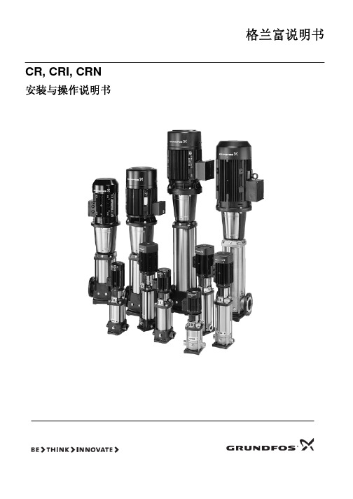
图3 9 最小入口压力的计算方法:
4.9 尺寸和重量 尺寸:请参见第 69 页图 C。 重量:请参见包装上的标签。
4.10 噪音等级ຫໍສະໝຸດ 请参见第 30/31 页图 D。5.安装
泵必须用螺栓通过法兰孔或者泵座孔安全在可靠的坚实的基 础上。 在安装泵时,必须严格按照以下过程序进行操作,以免损坏泵。
步骤
安装方法
4.5 最大进口压力 第 27/28 页图 B 标示了进口最大压力。但是,泵入口压力加 泵在闭阀时的扬程必须低于最大允许压力。 应该如第 27/28 页图 B 所示,压力测试在所示压力的 1.5 倍 下进行。
4.6 最小流量 由于过热的危险,泵不应该工作在最小流量状态下。 下图显示在相应温度下,最小流量占正常流量的百分比。 虚线为空气冷却曲线顶点。
CR, CRI, CRN
安装与操作说明书
格兰富说明书
设计标准申明
我们格兰富公司申明:在我们销售的职责范围内,对于 CR,CRI 和 CRN 型号的产品,符合欧共体成员国试行法工作委员会指 令性文件,相关文件如下: —机械(98/37/欧共体).
采用标准:EN ISO 12100.[译者注:英语 国际标准 12100] —电磁相容性(89/336/欧洲经济共同体).
·安装有功率最大为 11kW 的格兰富 MG 电机的 CR,CRN 32,45,64,90 泵,应该通过提升泵端部的环状螺母来提升 泵。
·安装有功率在 15kW 以上的西门子电机的 CR,CRN 32,45, 64,90 泵,应该通过提升电机法兰上的的环状螺栓来提升泵。
·对于安装除上述之外的其它型号的电机的泵,建议用皮带等
在开始安装之前,应该仔细阅读如下安装和操作
说明。安装和操作也应该参照当地的有关法规或
广一P-DLS立式多级多出口离心泵

末级出水口级数为6级(泵总级数为6级) 第I出水口级数为3级 规定点单级扬程为20mm 规定点流量为108m3/h 立式多级多出水口离心泵 吸入口直径100mm
GU G DLS型泵配4级电机,转速1450r/min N 总流量Q=30~200m3/h
总扬程H=40~252m采用调整水泵级数达到。使用温度小于80℃清水。 本型泵可以多出水口同时工作,也可以单出水口工作。单出口时为该泵的额定流量。若两个出口同时工作时,两
转速 n
(r/min) 1480
1480
1480
1480
1480
1480
1480
1480 1480
效率 η (%)
59 70 69 59 70 69 59 70 69 59 70 69 59 70 69 59 70 69 59 70 69 59 70 69 59 70 69
轴功率 电机功率 汽蚀余量 叶轮直径 总重量
UA Y G DLS型泵结构
UANG YI 1. 电机座 G2 拉紧螺栓
3. 上轴承
G 4. 出水段 N 5. 平键
6. 导水叶
A 7. 叶轮 Y 8. 中间出水段
9. 中段
I U G 10. 轴套 11. 轴
12. 轴套螺母(右旋)
G N 13. 下轴承 14. 下轴承套
GYI GUA15. 进水段
P
(NPSH)r
(kW)
kW
(m) (mm) (kg)
6.28
11
2.1
8.4
2.2
9.23 y160M-4 2.8
9.42
15
2.1
12.6
2.2
13.8 y160M-4 2.8
立式多级泵操作规程(正式)
立式多级泵操作规程(正式)
Standardize The Management Mechanism To Make The Personnel In The Organization Operate According To The Established Standards And Reach The Expected Level.
使用备注:本文档可用在日常工作场景,通过对管理机制、管理原则、管理方法以及管理机构进行设置固定的规范,从而使得组织内人员按照既定标准、规范的要求进行操作,使日常工作或活动达到预期的水平。
下载后就可自由编辑。
一、起动前准备
1、用手拨转电机,叶轮应无卡磨现象,转动灵活;
2、打开进口阀门,打开排气阀使液体充满整个泵腔,然后关闭排气阀;
3、严禁机械密封在干磨情况下工作,应先用手盘动泵联轴器几圈以使润滑水进入机械密封端面,避免突然起动造成机械密封断裂损坏。
4、点动电机,确定转向是否正确。
二、起动与运行
1、全开进口阀门,管闭吐出管路阀门;
2、接通电源,当泵达到正常转速后,再逐渐打开吐出管路上的阀门,并调节到所需工况;
3、注意观察仪表读数,检查轴封泄漏情况,正常时机械密封泄漏为3滴/分,检查电机、轴承处温升≤70℃,如果发现异常情况,应及时处理。
三、停车
1、逐渐关闭吐出管路阀门,切断电源;
2、关闭进口阀门;
3、如环境温度低于0℃,应将泵内液体放尽,以免冻裂;
4、如长期停用,应将泵拆卸清洗,包装保管。
请在这里输入公司或组织的名字
Please enter the name of the company or organization here。
立式多级离心泵安装使用说明书

立式多级离心泵安装使用说明书系列: MVA, MVS代斯米泵业技术有限公司电话: +45 96 32 81 11传真: +45 98 17 54 99邮件: ***************网站: 说明书: T1536 语言:中文版本:A1(03/20)目录1手册说明 (4)1.1前言 (4)1.2图标和符号 (4)2担保 (5)2.1 担保条款 (5)3产品 (6)3.1 产品介绍 (6)3.2 型号说明 (6)3.3 机械密封代号 (6)3.4 额定电流 (7)4安全与环境 (8)4.1通用 (8)4.2用户 (8)4.3安全措施 (8)4.4安全保护措施 (8)4.5环境方面 (9)5用途及使用范围 (10)5.1产品特点 (10)5.2用途 (10)5.3使用范围 (10)5.4工作介质 (10)6技术参数 (11)6.1环境温度 (11)6.2液体温度 (11)6.3最小进口压力的计算方法 (11)6.4压力与温度 (12)6.5电气参数 (12)6.6电机起/停次数 (12)6.7尺寸及重量 (12)6.8噪音等级 (12)7安装及使用前注意事项 (13)7.1安装时请按照以下事项操作,以免损坏泵 (13)7.2启动泵前检查 (14)7.3启动步骤 (15)8性能参数 (16)9保养 (17)10运输储存 (18)10.1运输 (18)10.2存储 (18)11故障解决 (19)12尺寸图 (21)13爆炸图 (29)1 手册说明1.1 前言本手册包含了正确、可靠和有效操作及使用产品的重要信息。
遵守操作说明对于确保产品的可靠性和较长的使用寿命以及避免任何风险都是至关重要的。
本章包含关于本手册和一般安全的信息。
以下章节提供了关于产品的正常使用、安装、维护和修理的信息。
•熟悉手册内容。
•准确地遵循指示和说明。
•按照手册,永远不要改变操作要求的顺序。
•将本手册或本手册的副本放在产品附近的固定位置,以便所有操作人员都能使用。
QDL不锈钢轻型多级泵使用说明书

■QDL、QDLF不锈钢轻型多级离心泵■QDL/QDLF轻型不锈钢多级离心泵上海沈泉泵阀制造有限公司■QDL 、QDLF 不锈钢轻型多级离心泵■☆QDL2/QDLF2轻型立式多级离心泵 管路连接方式工作条件冷热清洁的,非易燃易爆并不含有固体颗粒或纤维的液体; 液体温度:-15℃至+120℃ 环境温度:最高+40℃最小入口压力:根据NPSH 曲线+最小安全扬程量0.5米水头。
尺寸及重量性能表泵型号 配用电机 (KW) Q m3/h1 1.2 1.6 2.0 2.4 2.8 3.2 3.5 QDL2-20 0.37 18 17 16 15 13 12 10 8 QDL2-30 0.37 27 26 24 22 20 18 15 2 QDL2-40 0.55 36 35 33 30 26 24 20 16 QDL2-50 0.55 45 43 40 37 33 30 24 20 QDL2-60 0.75 53 52 50 45 40 36 30 24 QDL2-70 0.75 63 61 57 52 47 41 35 28 QDL2-90 1.1 80 78 73 67 61 54 45 37 QDL2-110 1.1 98 95 89 82 73 64 54 44 QDL2-130 1.5 116 114 106 98 89 78 65 52 QDL2-150 1.5 134 130 123 112 100 90 7360 QDL2-180 2.2 161 157 148 136 121 108 91 76 QDL2-220 2.2 197 192 180 165 148 130 110 90 QDL2-2603.0H m232228214198179158130110焊接(快装接管) DIN25mm或32mm 螺纹(椭圆法兰)ZG1"或ZGl1/4”尺 寸(毫米) 泵型号B1B2 BI+B2 D1 D2 重量(公斤)QDL2-20 220 225 445 145 11020 QDL2-30 238 225 463 145 11020 QDL2-40 256 225 481 145 11020 QDL2-50 274 225 499 145 11020 QDL2-60 297 225 522 145 11025 QDL2-70 315 225 540 145 11025 QDL2-90 351 245 596 170 15030 QDL2-110 387 245 632 170 15030 QDL2-130 440 245 685 170 15035 QDL2-150 476 245 72l 170 15035 QDL2-180 530 265 795 180 15540 QDL2-220 602 265 867 180 15545 QDL2-26068229097218015550上海沈泉泵阀制造有限公司型号意义性能曲线应用范围★ 普通型适用于液体传输,冷热清洁水、软化水的循环和增压。
GDL多级管道泵使用说明书

上海沈泉泵阀制造有限公司☆ 产品简介及特点GDL型多级管道离心泵是我单位在国内外优秀泵型之基础上结合用户的使用要求及消防有关标准,并根据JB/TQ6435-92标准设计制造的新一代产品。
本型泵采用立式节段式外加不锈钢壳体结构,使得泵的进出口位于同一水平线上且口径相同,能象阀门一样安装于管路之中,它同时集中了多级泵之高压,立式泵之占地面积小及管道泵之安装方便的优点,同时由于采用了优秀的水力模型,所以还具有高效节能,运行平稳等优点,且轴封采用耐磨机械密封,无泄漏使用寿命长。
为了能更好地满足用户的要求,本单位还开发了出水口位于上部的GDLS型,其进出口可以不同的相对位置(0°、90°、180°)安装,使用极为方便。
为了使用户能更加安全、可靠的使用该型泵,本单位特别研制了便拆式结构型,它除拥有GDL、GDLS的一切优点外,更为您更换机械密封等易损件提供了更加方便,快捷、省力的途径,使本型泵更无忧运行与维护。
应用范围本型泵主要适用于高压运行系统中冷热清水的循环和增压、高层建筑多台泵并联供水、消防、锅炉给水和冷却水系统及各种冲洗液的输送等。
工作条件1.本型泵可输送清水或物理化学性质类似于清水的液体;2.液体温度:-15℃~+120℃;3.工作压力:最大工作压力<2.5MPa,即系统压力=入口压力+闭阀工作时的压力<2.5MPa;4.周围环境的温度应低于40℃,相对湿度不超过95%;5.输送含腐蚀性介质及热液体时,请于订货时提出,以便采用特殊材质满足使用要求。
☆ 型号意义☆ 结构简图1 泵体 11 联轴器 1 泵体 11联接座 1吸入段 11 联接座2 拉紧螺栓 12 联接座 2 拉紧螺栓 12密封座 2拉紧螺栓 12 密封座3 外筒 13 气嘴 3 外筒 13轴承座 3外筒 13 复合轴承4 叶轮 14 机械密封 4 叶轮 14机械密封 4叶轮 14 轴承座5 时轮挡套 15 轴 5 叶轮挡套 15轴 5叶轮挡套 15 机械密封6 轴套 16 中段 6 轴套 16中段 6密封垫 16 轴7 密封垫 17 轴套螺母 7 密封垫 17轴套螺母 7螺母 17 中段 8 螺母 18 轴瓦 8 螺母 18轴瓦8出水段 18 轴套螺母 9 销 19 回水管部件 9 联轴器 19回水管部件9联轴器 19 轴瓦 10 电机10 电机10电机☆型谱图☆ 性能曲线图25GDL2 25GDL240GDL6 50GDL1250GDL18 65GDL2480GDL36 80GDL54100GDL72 125GDL100150GDL-160☆性能参数表流量功率(KW)型号(m3/h) (L/S) 扬程(m) 效率(%)转速(r/min)轴功率电机功率 汽蚀余量(m) 进出 口径 (mm) 高度 H (m) 重量(kg)高度h1 (m)25GDL2-12×31.4 22.4 0.39 0.56 0.67 38 36 33 23 30 32 2900 0.630.650.67 1.1 1.4 1.7 1.8 25 606 58 12525GDL2-12×41.4 22.4 0.39 0.56 0.67 50 48 44 23 30 32 2900 0.830.870.90 1.1 1.4 1.7 1.8 25 646 62 16525GDL2-12×51.4 22.4 0.39 0.56 0.67 63 60 55 23 30 32 2900 1.041.091.12 1.5 1.4 1.7 1.8 25 711 68 20525GDL2-12×61.4 22.4 0.39 0.56 0.67 76 72 66 23 30 32 2900 1.261.301.35 1.5 1.4 1.7 1.8 25 751 72 245 25GDL2-12×71.4 22.4 0.39 0.56 0.67 88 84 77 23 30 32 2900 1.461.521.57 2.2 1.4 1.7 1.8 25 816 78 28525fiDL2-12×81.4 22.4 0.39 0.56 0.67 101 96 88 23 30 32 2900 1.631.741.80 2.2 1.4 1.7 1.8 25 856 82 32525GDL2-12×91.4 22.4 0.39 0.56 0.67 114 108 99 23 30 32 2900 1.891.962.02 2.2 1.4 1.7 1.8 25 896 86 36525GDL2-12×101.4 22.4 0.39 0.56 0.67 126 120 110 23 30 32 2900 2.012.172.24 3 1.4 1.7 1.8 25 981 98 40525GDL2-12×111.4 22.4 0.39 0.56 0.67 139 132 121 23 30 32 2900 2.312.392.47 3 1.4 1.7 1.8 25 1021 102 44525GDL2-12×121.4 22.40.39 0.56 0.67152 144 13223 30 3229002.522.612.7031.4 1.7 1.825106110648525GDL4-11×3 2.844.80.781.111.33363328.532404129000.860.900.911.11.41.71.825 606 58 12525GDL4-11×4 2.844.80.781.111.3348443832404129001.141.201.211.51.41.71.825 671 65 16525GDL4-11×5 2.844.80.781.111.33605547.532404129001.431.501.512.21.41.71.825 736 72 20525GDL4-11×6 2.844.80.781.111.3372665732404129001.721.801.822.21.41.71.825 776 76 24525GDL4-11×7 2.844.80.781.111.33847766.532404129002.002.102.1231.41.71.825 861 86 28525GDL4-11×8 2.844.80.781.111.3396887632404129002.292.402.4231.41.71.825 901 90 32525GDL4-11×9 2.844.80.781.111.331089985.532404129002.572.702.7331.41.71.825 941 94 36525GDL4-11×10 2.844.80.781.111.331201109532404129002.863.003.0341.41.71.825 1011 110 40525GDL4-11×11 2.844.80.781.111.33132121104.532404129003.143.303.3341.41.71.825 1051 114 44525GDL4-11×12 2.844.80.781.111.3314413211432404129003.433.603.6441.41.71.825 1091 118 48525GDL4-11×13 2.844.80.781.111.33156143123.532404129003.723.903.9441.41.71.825 1131 122525注:1: GDLS、GDL-B、GDLS-B型除重量H尺寸稍有不同外其性能参数与GDL型相同。
多级 立式 离心泵 使用说明

多级立式离心泵是一种常用的工业设备,广泛应用于供水、加压输送、供暖、空调等领域。
在使用多级立式离心泵时,需要遵守一定的操作规程和注意事项,以确保设备的安全运行和有效工作。
下面将针对多级立式离心泵的使用说明进行详细介绍。
一、设备介绍1. 多级立式离心泵是一种由进口轴承、轴封、泵体、叶轮等部件组成的泵类设备。
它具有高效节能、流量大、扬程高等特点,适用于中小型工业和民用建筑的供水和水循环系统。
2. 多级立式离心泵可根据用户的需求选择不同的材质,例如不锈钢、铸铁、铜等,以适应不同的工作环境和介质。
3. 设备采用了先进的结构设计和制造工艺,确保了设备的稳定性和可靠性。
多级立式离心泵的安装、使用、维护都比较简便。
二、操作规程1. 在启动多级立式离心泵之前,需要先检查设备的电源接线是否牢固,电机是否正常接地。
2. 启动时,应按照设备的操作说明书操作,以免因操作不当引起损坏或事故。
3. 注意监测设备的电流、电压和运行声音,确保设备的正常运行状态。
三、设备维护1. 定期检查设备的轴承、轴封、叶轮等部件的磨损情况,发现问题及时更换。
2. 维护人员应具备一定的机械和电气知识,能够及时发现和处理设备的故障。
3. 在设备不使用时,需要及时清洗泵体内部的介质并进行防腐处理,以延长设备的使用寿命。
四、安全注意事项1. 在使用多级立式离心泵时,需保持设备周围的清洁和整洁,避免进入异物影响设备的正常工作。
2. 禁止在设备运行中进行维修和保养操作,以免发生危险。
3. 正确操作设备,避免超负荷运行,以免损坏设备和降低设备的寿命。
五、环保要求1. 多级立式离心泵使用过程中,需要注意减少设备的能耗和杜绝泄漏现象。
2. 设备使用寿命结束后,应按照环保要求进行处理,避免对环境造成污染。
六、结语通过以上介绍,我们对多级立式离心泵的使用说明有了更加全面的了解。
在实际操作中,我们需要严格依照设备的说明书和操作规程来进行操作,从而确保设备的正常运行和安全工作。
QS潜水多级泵使用说明书

■QS潜水多级离心泵■上海沈泉泵阀制造有限公司☆ 使用需知一、电机使用前必须灌满清水,拧紧注水放气螺栓,否则不准使用。
二、陆地试运转不得超过—秒。
三、电泵不准倒卧或斜倾使用。
四、电动机必须完全潜入水中,但潜入深度府不大于70米。
五、引线与电缆接头按规定操作(详见附图)。
六、订购高扬程潜水电泵请参阅《高扬程潜水电泵型谱》及《高扬程潜水电泵使用手册》。
☆ 电缆接法1、去掉绝缘层,不得损坏导体。
2、3根导线长短错开。
3、刮净导体绝缘漆膜。
4、保证接头不存有油、水和其 它污物。
1、把接头分为数股(不小于6股)均匀分开。
2、把两个接头交叉在一起,交叉长度以两端线头与绝缘层对齐为宜。
1、把各股紧合一起,从中部分出一股向一端缠绕,使各股一次缠绕完毕。
2、另一端以同样方法进行。
3、用手钳把接头缠紧,有条件时可把接头挂锡,使效果更佳。
1、先用普通黑胶布对缠绕部分包扎两层,包扎要紧。
2、亚敏胶粘带(黑色)包扎3层,每包扎一层用手挤压一次,保证包扎质量。
3、最后用塑料绝缘胶带包扎两层即可。
1、先整理好小接头,用亚敏胶粘带包扎5层(不得少于4层)并要包住电缆护套部分25mm以上。
2、用塑料绝缘胶带包3层,两端部超过前一层5mm以上左右。
3、为防止下井时增破包扎层,最好再用5 0 m m宽,长度适当的自行车内胎,锉净两面,涂上胶水,在接头外面缠绕一层,起保护作用。
采用电弧焊接接头更佳。
也可采用套管冷压接头方法。
在包扎第一层黑胶布时,不得让铜丝头漏出或扎透胶布请 您 注 意 1、包扎接头前需要检查电机的绝缘,符合说明书要求方可接线,接头包好后必须在室温水中浸泡12小时后,测量绝缘,达到要求后方可下井。
2、两种胶带均有弹性,包扎时应拉紧,最后一层包完后原处绕几圈,防止长时间后脱开。
3、每个接头在包扎中,当胶带缠绕到两端头时,后缠绕层必须超出前层5 mm以上。
4、包扎三根单蕊引线时,把亚敏胶带卷成三角形状垫入孔隙处,预防水渗入。
立式多级泵操作规程通用版
操作规程编号:YTO-FS-PD377立式多级泵操作规程通用版In Order T o Standardize The Management Of Daily Behavior, The Activities And T asks Are Controlled By The Determined Terms, So As T o Achieve The Effect Of Safe Production And Reduce Hidden Dangers.标准/ 权威/ 规范/ 实用Authoritative And Practical Standards立式多级泵操作规程通用版使用提示:本操作规程文件可用于工作中为规范日常行为与作业运行过程的管理,通过对确定的条款对活动和任务实施控制,使活动和任务在受控状态,从而达到安全生产和减少隐患的效果。
文件下载后可定制修改,请根据实际需要进行调整和使用。
一、起动前准备1、用手拨转电机,叶轮应无卡磨现象,转动灵活;2、打开进口阀门,打开排气阀使液体充满整个泵腔,然后关闭排气阀;3、严禁机械密封在干磨情况下工作,应先用手盘动泵联轴器几圈以使润滑水进入机械密封端面,避免突然起动造成机械密封断裂损坏。
4、点动电机,确定转向是否正确。
二、起动与运行1、全开进口阀门,管闭吐出管路阀门;2、接通电源,当泵达到正常转速后,再逐渐打开吐出管路上的阀门,并调节到所需工况;3、注意观察仪表读数,检查轴封泄漏情况,正常时机械密封泄漏为3滴/分,检查电机、轴承处温升≤70℃,如果发现异常情况,应及时处理。
三、停车1、逐渐关闭吐出管路阀门,切断电源;2、关闭进口阀门;3、如环境温度低于0℃,应将泵内液体放尽,以免冻裂;4、如长期停用,应将泵拆卸清洗,包装保管。
该位置可输入公司/组织对应的名字地址The Name Of The Organization Can Be Entered In This Location。
DL立式多级离心泵品牌型号及参数说明
■DL立式多级离心泵■上海沈泉泵阀制造有限公司☆概述DL 、DLR 型泵系立式单吸多级分段式离心泵,供输送不含固体颗粒的清水及物理性质类似于水的液体之用。
主要用于高层建筑供水,也可应用于厂矿给排水、输送液体的流量范围为 4.9~200m3/h ,扬程范围为22~239m ,配套功率范围为1.5~160KW ,口径范围为φ40~φ150mm 。
本厂生产的DL 、DLR 型系列泵质量可靠、性能稳定,欢迎各新老客户选购。
☆ 用途DL 、DLR 型系列泵适用于工业和城市给排水、高层建筑增压送水、消防增压、远距离送水、采暖、浴室、锅炉冷暖水循环增压、空调制冷系统送水及设备配套等场合。
DL 型介质使用温度不超过80℃,DLR 型介质使用温度不超过l20℃。
☆ 结构说明1 进水段2 中段3 密封环4 叶轮挡套5 叶轮6 平衡鼓7 平衡套8 出水段9 机械密封 10 填料体 11 轴套 12 挡水套 13 轴承盒 14 推力球轴承 15 轴承盖 16 连接架 17 连轴器 18 水中轴承套 19 水中轴承 20 下轴套 21 卡环 22 卡环套 23 导叶管 24 导叶 25 叶轮密封环 26 出水段导叶 27 灌水回水管 28 填料压盖 29 电动机DL 型泵由电机和泵两部分组成,电机为Y 型三相导步电机,泵和嘲采用联轴器连接,整体为刚性连接,使用时无需校正。
泵由定子部分利转子部分组成。
泵定子部分由进水段、中段、导叶、出水段、填料函体等零件组成。
为防止定子磨损,定子上装有密封环、平衡套等,磨损后可用备件更换。
转子部分由轴、中轮、平衡鼓等组成。
转子下端为水润滑轴承,上部为角接触球轴承,泵的轴向力绝大部分由平衡鼓来承担,其余小部分残余轴向力由角接触球轴承来承受。
进水段、中段和出水段的结合面用纸垫通过拉紧达到密封。
轴封采用填料或机械密封,用户可根据需要选择。
泵旋转方向从驱动端向下看为逆时针方向转动。
☆ 主要特点1.泵结构紧凑、体积小、外形美观,其立式结构决定安装占地面积小,其重心重合于泵脚中心,因而增强了泵的运行稳定性和使用寿命。