南高齿偏航齿轮箱使用说明书
齿轮箱操作手册.
用以驱动风力发电机的PPSC1290-MY型齿轮箱操作手册Jahnel-Kestermann Getriebewerke 有限公司Hunscheidtstrasse 街116号44789 Bochum市(德国)操作手册内容目录技术数据----------------------------------------------------安全------------------------------------------------------------100-0003-01 综述------------------------------------------------------------100-0003-02 运输------------------------------------------------------------100-0012-03 结构和功能---------------------------------------------------350-0019-04 装配-------------------------------------------------------------100-0006-05 准备工作-------------------------------------------------------100-0004-06 启动-------------------------------------------------------------100-0001-07 运行-------------------------------------------------------------100-0001-08 维护-------------------------------------------------------------100-0006-11 推荐的润滑剂-------------------------------------------------100-0006-11在运行之前请仔细阅读并遵守操作手册和安全措施1,采购订货数据客户名称客户编号合同编号2,订货数据齿轮箱型号-------------------------------------------------PPSC1290-MY 外形尺寸图纸编号-----------------------------------------零件图纸编号----------------------------------------------零件表编号------------------------------------------------- 40 267 691 00 订货编号3,齿轮箱数据3.1 齿轮箱使用范围齿轮箱应使用在满足规范中规定的载荷和条件的风力发电机中。
齿轮箱说明书
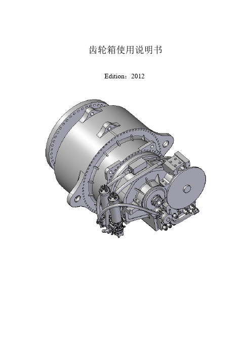
齿轮箱使用说明书Edition:2012版本升级记录从Edtion:2011升级到Edtion:2012版本的主要内容:1.在6.4章节中增加了严禁对齿轮箱进行敲击装配的提醒;2.在8.2章节中增加了对风机传动链长时间锁死对齿轮箱会造成严重损害的重要提示;3.在9.1章节中进一步明确了电机泵的启动关闭控制流程,删去了单速电机泵的控制流程;4.在9.2章节中进一步明确了风扇的启动和关闭控制流程,删去了单速风扇或水冷的的控制流程;5.在10章中重新整合本章的内容,并增加了10.9级螺栓预紧力矩检查标准。
目录1 前言 (5)2 开箱 (6)3技术参数 (7)3.1 铭牌 (7)3.2 应用领域 (7)4 安全事项 (8)4.1正常使用 (8)4.2客户义务 (8)4.3环境保护 (9)4.4特殊危险 (10)5 运输和储藏 (11)5.1运输 (11)5.2 储藏 (12)6齿轮箱的安装 (14)6.1 拆箱 (14)6.2 排油、去除防腐剂 (14)6.3高速轴连轴器的安装 (14)6.4 加油 (16)6.5 连接电路 (16)6.6 机舱试车前的检查 (16)6.7 机舱试车 (17)6.8 齿轮箱随机舱的运输 (17)7齿轮箱拆卸 (18)7.1拆除高速轴连轴器 (18)7.2防腐防锈处理 (18)8启动与停机 (19)8.1启动 (19)8.2齿轮箱的停机 (20)9监控要求 (22)9.1 电机泵的控制 (23)9.2 风扇或水冷的控制 (24)9.3运行温度 (24)9.4 油位检查 (25)9.5 取油样 (26)9.6油压 (26)9.7 齿轮箱内部检查 (27)10维护和修复 (28)10.1中分面及齿圈螺栓的检查 (28)10.2必须维护的项目 (29)10.3齿轮箱常见故障 (30)11润滑系统 (32)11.1润滑油 (32)11.2 换油 (33)11.3更换滤芯 (33)11.4安装滤芯 (34)12 重要事项 (35)12.1 空气滤清器 (35)12.2 滤芯 (35)12.3 润滑油 (35)1 前言用户在安装使用前请详细阅读本说明书。
南高齿高速箱介绍之欧阳主创编
系列往复式压缩机1.NGSS用齿轮箱为NGGS型及NGSD型齿轮箱延伸型,采用国际先进标准,应用公司十几年产品试制经验进行设计,选用一流设备,按ISO9001:2000质量控制体系程序,设计制造的高精度硬齿面高速齿轮箱。
可适用于汽轮机、燃气发电机、离心以及轴流风机、鼓风机、压缩机、高低压泵、裂化催化能量回收、制氧机、平衡机、军用与民用试验台等机组配套增(减)高速齿轮箱。
产品具有以下技术特点:1.高转速:产品最高转速30000r/min。
2.多规格:标准产品中心距192-545,并可根据用户要求进行非标设计。
3.高精度:齿轮精度达到ISO4-6级,动平衡精度达到ISO0.4-1.6。
4.高标准:齿轮精度标准为ISO1328-1:1995和ISO1328-2:1997,齿轮强度标准AGMA420.04-1975和AGMA421.06-1969。
齿轮箱设计检验标准API613-2003,齿轮材料热处理标准ISO6336-5:1996,振动检验标准API670-2000,润滑系统标准API614-1999。
5.高技术:产品采用三维CAD设计,采用有限元分析,齿形热弹性变形的修形,齿根喷丸强化工艺及轴系动态分析等公司最新研究成果。
6.高可靠度:齿轮箱设计寿命10年中心距规格:192、215、240、272、305、340、385、430、480、545 功率范围:11kW~1558kW最高转速:30000r/min 速比:6.3-182.大功率燃透平机专用高速齿轮箱主要用于透平机带动发电机、风机。
一般为单级减速传动,该种高速齿轮箱拥有承载能力大,节圆线速度高,防爆等特点。
齿轮箱设计检验按API613标准;齿轮强度按AGMA420.04, AGMA421.06;振动检验按API1670。
齿轮材料:17Cr2Ni2Mo、25Cr2Niv或20CrNi2Mo,渗碳、淬火、磨齿;圆柱齿轮精度:ISO1328-1:2001的3、4、5级,齿轮进行齿廓和螺旋线修整;齿轮材料和热处理质量按ISO6336-5:1996中的最高质量等级ME级控制;齿轮均进行齿根喷丸强化;齿面采用特殊处理;转子残余不平衡量按(ISO标准)G1.0 级进行;盘车装置安装于齿轮箱上采用电动盘车,或手动。
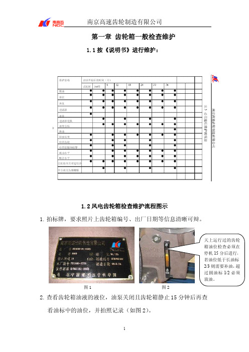
南高齿维护手册
2.将原有的电加热器拆下,清理孔及周围的原有胶层;
3.安装新的电加热器,如果是平面密封的加热器(例如 FD1660
机型),则在加热器套筒的密封面打胶 515,打胶时,利用小铲刀
将胶层轻轻的刮平,保证胶层平整、均匀;如果是螺纹密封的加
热器(例如 FD1775 机型),则在螺纹部分打密封胶 577;
4.重新添加齿轮箱润滑油,观察有无漏油现象,并连接加热器电
7. 查看风冷器有无漏油情况,灰尘污渍是否将风冷器堵死,需拍照 记录(实物见右上图)。
8. 开启电机泵,听油泵电机声音有无异常。 9. 打开天窗盖板,查看齿面状况:断齿、点蚀、较大凹坑、较重压
痕等异常情况;检查高速级、低速级齿面啮合情况,要求照片上 齿面啮合痕迹清晰可辩
3
南京高速齿轮制造有限公司
高速轴工作齿面 高速级啮合区喷油
源,查看加热器工作是否正常,在确定无漏油,加热器工作正常
的情况下,结束更换工作。
5.压力表、PT100
1.在更换时,不需要将齿轮箱内部润滑油放干净;
2.拆下需要更换的压力表或 PT 100,并清理螺孔周围的原有胶层,
在清理时要注意,防止异物通过螺孔进入齿轮箱内部并用清洗剂
清洗干净;若在液面以下,更换前做好接油准备并检查密封垫片
(3) 依次拧紧收缩盘各螺栓,直至收缩盘内外环高度差达到 要求的高度差为止。
15
南京高速齿轮制造有限公司 2.4 轴承温度报警问题处理方案: 1、确认 PT100 工作正常,若不正常,更换 PT100; 2、打开视孔盖并开启润滑系统,检查轴承喷油是否正常,检 查润滑系统的压力,若有问题,检查润滑系统; 3、检查高速轴对中,并记录数据。 4、观测运行时齿轮箱的振动及噪音,如有异常,分析产生原 因并检查相关零件。
齿轮箱说明书
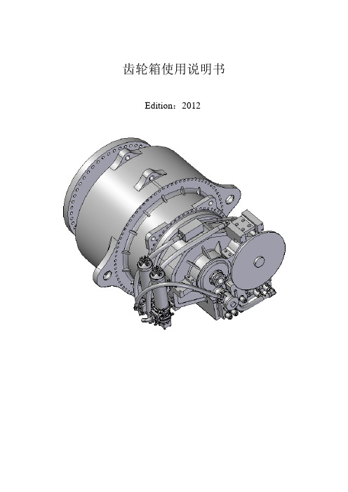
齿轮箱使用说明书Edition:2012版本升级记录从Edtion:2011升级到Edtion:2012版本的主要内容:1.在6.4章节中增加了严禁对齿轮箱进行敲击装配的提醒;2.在8.2章节中增加了对风机传动链长时间锁死对齿轮箱会造成严重损害的重要提示;3.在9.1章节中进一步明确了电机泵的启动关闭控制流程,删去了单速电机泵的控制流程;4.在9.2章节中进一步明确了风扇的启动和关闭控制流程,删去了单速风扇或水冷的的控制流程;5.在10章中重新整合本章的内容,并增加了10.9级螺栓预紧力矩检查标准。
目录1 前言 (5)2 开箱 (6)3技术参数 (7)3.1 铭牌 (7)3.2 应用领域 (7)4 安全事项 (8)4.1正常使用 (8)4.2客户义务 (8)4.3环境保护 (9)4.4特殊危险 (10)5 运输和储藏 (11)5.1运输 (11)5.2 储藏 (12)6齿轮箱的安装 (14)6.1 拆箱 (14)6.2 排油、去除防腐剂 (14)6.3高速轴连轴器的安装 (14)6.4 加油 (16)6.5 连接电路 (16)6.6 机舱试车前的检查 (16)6.7 机舱试车 (17)6.8 齿轮箱随机舱的运输 (17)7齿轮箱拆卸 (18)7.1拆除高速轴连轴器 (18)7.2防腐防锈处理 (18)8启动与停机 (19)8.1启动 (19)8.2齿轮箱的停机 (20)9监控要求 (22)9.1 电机泵的控制 (23)9.2 风扇或水冷的控制 (24)9.3运行温度 (24)9.4 油位检查 (25)9.5 取油样 (26)9.6油压 (26)9.7 齿轮箱内部检查 (27)10维护和修复 (28)10.1中分面及齿圈螺栓的检查 (28)10.2必须维护的项目 (29)10.3齿轮箱常见故障 (30)11润滑系统 (32)11.1润滑油 (32)11.2 换油 (33)11.3更换滤芯 (33)11.4安装滤芯 (34)12 重要事项 (35)12.1 空气滤清器 (35)12.2 滤芯 (35)12.3 润滑油 (35)1 前言用户在安装使用前请详细阅读本说明书。
1.5MW南高齿齿轮箱拆检步骤

齿轮箱拆检步骤一、放油工具:吊机(10t/50t)、吊带(两根)、吊链、10mm内六角、油桶二、拆吊油附属系统及水冷却系统工具:吊机(10t/50t)、吊带(两根)、活动扳手(40mm)、内六角(一套)、开口扳手(一套)方法:拆除螺栓及油管(注意齿轮箱内残余的润滑油),并用吊机移除水冷系统及润滑油泵。
三、拆齿轮箱低速轴涨紧套工具:吊机(10t/50t)、吊带(宽)、吊链、千斤顶、砂纸、长木棍方法:除漆后用砂纸打磨干净,将吊带环绕在涨紧套上,用吊机加以保护,再使用木棍将涨紧套玩外撬,最后使用千斤顶将涨紧套顶出。
四、拆吊高速轴外端盖工具:吊机(10t/50t)、吊链、H16内六角、棘轮、M16吊环(两个)方法:用H16内六角以及棘轮将螺栓拆除,利用顶丝和吊机将端盖移除五、拆吊平行级上部壳体工具:吊机(10t/50t)、吊链、液压扳手、H19内六角、H27内六角、棘轮、通口千斤顶(ssz270-40)、螺杆、M36吊环(一个)方法:用H19、H27内六角、液压扳手和棘轮将螺栓拆除,使用通口千斤顶和螺杆将定位销拉出来,利用吊机将壳体移除。
六、拆吊空心轴工具:吊机(10t/50t)、吊链、H16内六角、棘轮、16mm弯头螺杆方法:用H16内六角和棘轮将螺栓拆除,利用吊机将其移除。
七、拆吊高速轴工具:吊机(10t/50t)、吊链、吊环工具:吊机(10t/50t)、吊链、H19内六角、H27内六角、棘轮、通口千斤顶(ssz270-40)、螺杆、M36吊环(一个)方法:同步骤五九、拆吊平行级大齿轮工具:吊机(10t/50t)、吊链、M16吊环(两个)、吊带、开口扳手方法:将挡油板拆除,利用吊机将其移除。
工具:吊机(10t/50t)、吊链、36套筒、棘轮、液压扳手、千斤顶、撬棍、M36吊环(4个)方法:用千斤顶将壳体往上顶,使壳体在水平方向缓慢上升,待定位销紧力消失,利用撬棍和吊机将其移除(空间过小,没有预先拆除定位销)。
南高齿偏航齿轮箱使用说明书
偏航变桨技术质量部
偏航齿轮箱使用说明书
南京高速齿轮制造有限公司
2010/3/11
1
偏航变桨技术质量部
3
偏航变桨技术质量部
四、运输、存放 齿轮箱运输、存放时应处于垂直状态,按图 1 状态进行运输、存放。不
允许水平状态下进行运输、存放(见图 2)。
图 1 运输、存放时的正确状态
图 2 运输、存放时的不正确状态ห้องสมุดไป่ตู้
齿轮箱运输、存放时应放置在木制支架上或平滑干燥的基础上,请勿
直接放在水泥地面上。运输时应进行可靠的固定,防止撞击,防止轴转动。
6
重新装螺塞时,螺纹处应 涂螺纹胶,loctite 271
油杯
图 3 添加润滑脂处
七、启动与运行 启动前的检查
5
偏航变桨技术质量部
启动前应按次序进行下列检查,确认无误时方可进行试运行: ① 安装位置的准确性; ② 各紧固件紧固的可靠性; ③ 电机接线是否正确; 八、 维修保养 8.1 应保持润滑系统清洁,采取措施防止灰尘、湿气及化学物质进入齿 轮及润滑系统,下列情况应特别加强对油的检查分析: ① 环境温度引起箱体内壁产生水珠,使油污染形成沉淀; ② 齿轮箱内油的温度经常在 80℃以上; ③ 因间断性的重载引起油温急速上升之后冷却; ④ 齿轮箱在极度潮湿的情况下工作; 8.2 检查到齿轮箱油位过低时,应及时补充油; 8.3 若齿轮箱长期停机,应按长期储存要求进行防锈保养;
齿轮箱严禁在室外存放,其防腐期为发货之日起在室内存放 6 个月(。如
(整理)南京高精齿轮MLX110立磨减速机使用说明书.

1.概述MLX110立式水泥磨减速齿轮箱采用圆锥齿轮与行星齿轮联合传动形式,一对直角传动的圆锥齿轮与一套输入轴为垂直向上的行星传动,通过双齿联轴器将二者联接起来。
太阳轮用球头支承在推力盘上,立式磨机的轴向支承由一个扇形的油模可倾瓦推力轴承来承受,这两个自由度使内圈及三个行星轮受力均匀。
内齿圈被刚性的固定在箱体上,设计成圆筒状箱体为轴向推力轴承提供了理想的支撑形式。
另外,圆筒状箱体的内外壁都配置了对称的加强筋,是箱体有很好的刚性。
输出轴与行星架焊成一体使结构简单合理。
圆锥齿轮采用克林根贝尔齿形的螺旋齿,太阳轮,行星轮为渐开线直齿,这些齿轮均采用高强度的渗碳钢,齿轮经渗碳磨齿具有较高的精度。
减速齿轮箱的所有支承轴承均采用滚动轴承,轴向推力轴承为可倾瓦推力轴承,由十六块扇形轴瓦组成,它承受立式磨机的轴向推力。
工作时轴瓦直接浸泡在油池中,并经过环形喷嘴不断提供新鲜润滑油,使油池始终保持一定的液面高度,当滑油系统突然停止工作或发生其它机械故障时,使磨机仍然能工作一段时间。
滑油系统采用独立的油站,并有油压,油温的自动保护系统,使全套装置工作时安全可靠。
2. 主齿轮箱技术性能参数:齿轮箱连续功率:N=1250KW 输入转速:n1=994r/min额定垂直静载荷:F静=2750KN 垂直动负荷:F动=8250KN减速比:I=31.058 齿轮箱重量(千克):G=35183齿轮箱用润滑油:硫磷型极压工业齿轮油N320齿轮箱用油入口温度:37~43°C3 减速齿轮箱的安装与找正:3.1地基:减速齿轮箱必须安装在刚性好,无振动,水平的地基上,例减速齿轮箱可安装在支承面经过机械加工的基础框架上,基础框架须与水泥基础浇灌成一体。
经找正后的齿轮箱心须用锥销定位后再用螺栓把其也基础框架连接在一起。
3.2找正:3.2.1减速齿轮箱与主电机找正齿轮箱与主电机相连接的输入轴在运转必须与电机轴同心。
为了满足这个需要,其轴向与经向跳动必须用专用测量装置来测量,具如需要R>200mm,轴向跳动值可相应增大3.2.2减速齿轮箱与磨机的安装与找正:减速齿轮箱与磨机之间的安装工作必须正确而细致的进行。
齿轮箱操作控制说明书
INSTRUCTIONS FOR OPERATION, CONTROL,MAINTENANCE ANDMOUNTINGGEARBOX LUBRICATIONKTM 1600CONTENT0. INTRODUCTION 31. EQUIPMENT DESCRIPTION 3 1.1 Technical parameters 3 1.2 Packaging, transportation, conservation 3 1.3 Mounting 41.4 Documentation 42. DESCRIPTION OF FUNCTION 43. ELECTRIC CONTROL 4 3.1 Electric appliances 43.2 Interlocking, signaling, control 54. PUTTING INTO OPERATION 5 4.1 Oil filling of gearbox 5 4.2 Flushing and testing 5 4.3 Working pressure set up 6 4.4 Flow rate signaling 6 4.5 Pressure control 6 4.6 Oil filtration 6 4.7 Temperature control 64.8 Level control 65. EQUIPMENT OPERATION 66. EQUIPMENT MAINTENANCE 77. SPARE PARTS AND GASKETS 8 7.1 Instructions for spare parts and gaskets ordering 80. INTRODUCTIONWe provide you this accompanying documentation to supplied equipment. You will find technical parameters and instructions for correct putting the equipment into operation, for control and maintenance.1. EQUIPMENT DESCRIPTIONThe equipment consists of the following parts : - aggregate- pipe distributionLubrication aggregate is a source of lubrication oil. It consists of the frame on which lubrication unit is placed (pump and electric motor), filter, cooler, contact thermometer, safety valve and flow rate switch.Pipe distribution is made with the pipes connected with flat flanges and closing valves. Pipe distribution is connected to the gearbox with hoses or rubber compensators for vibration compensation. On the gearbox body there is a level gauge with level switch and ball valve for discharge.Lubrication function is shown on the functional diagram dr.no. 4-OCH-31 011.1.1 Technical parametersLubrication aggregate∙Tank capacity -∙Delivered quantity 43 dm3min-1∙Safety pressure 10 bar∙Max. input 1,5 kW∙Electric motor revolutions 1400 min-1∙Working liquid Mineral oil ISO VG 100 ( according to DIN 51 519 ) ∙Working temperature 20 - 55 °C.∙Filtration rate 25 μm∙Heating In gearbox – 2 x 750 W∙Cooling Water cooler, P CH=18 kWat ∆t=25°C∙Electric motors voltage ~400 V, 50 Hz∙Elements voltage 24 V DC1.2 Packaging, transportation, conservationAll the parts of lubrication system are conserved with the lubrication oil and the parts of pipe distribution and the outlets from the aggregate and separate elements are plugged for transportation. Lubrication aggregate is possible to replace only for the lower part of the frame.1.3 MountingEquipment mounting is performed by the specialists for lubrication equipment or by the staff properly trained. Mounting shall be done in accordance with attached technical documentation.All parts of the pipe distribution shall be properly cleaned prior to mounting.The lubrication aggregate is mounted to the machine prior to the assembly of pipe distribution and is fixed with anchor bolts to the footing. After proper cleaning of the inlets the lubric. aggregate is connected with the gearbox by means of pipe distribution. Connection spots are shown on the lubrication aggregate layout drawing dr.no. 3-OCH-31 128and piping distribution is connected according to the functional diagram dr.no. 4-OCH-31 011.Mounting shall be documented with the assembly book mentioning the firm that performed mounting.1.4 DocumentationThe lubrication aggregate is usually supplied with :∙The instructions for operation, control, maintenance and mounting∙functional diagram∙specification of elements∙layout drawing of lubrication aggregate∙motor list2. DESCRIPTION OF FUNCTIONLubrication liquid is sucked with gear hydrogenerator (pos. 103) from the gearbox housing. Liquid flows further under pressure about 1÷3 bar through double filter (pos. 107) and the cooler (pos. 119) back to the gearbox housing on three lubricated spots. Filter clogging signal is electric.Pressure part of lubrication circuit is secured with pressure about 10 bar by means of pressure valve mounted on gear hydrogenerator (pos. 103).Working pressure is possible to control visually by means of manometer (pos. 109).Flow rate of lubrication oil is controlled with flow rate switch (pos. 114).Liquid temperature in gearbox is remote controlled with temperature sensor (pos. 117).Minimal oil level in the gearbox is signaled with level switch (pos. 122) mounted on gearbox.Remote control of pickup values is terminated on control panel.3. ELECTRIC CONTROL3.1 Electric appliancesPos. 102 - electric motor FCPA 90 L-4, 1,5 kW, 1400 min-1, 400 VPos. 106 - terminal switch DIN EN 50 041 – A1 250 VPos. 107 - filter clogging indicator AE.70.P.-.B, 3 VA, 24 VPos. 114 - flow rate sensor SI5000, 0,4 A, 24 VPos. 117 - temperature sensor T1005, 4÷20 mA, 230 VPos. 119 - water valve AB 21-23 / G3/4-G24 Z4, 12W, 24 VDCPos. 122 - level switch SNK 176 V-C-O-12-R, 0,5A, 24 VPos. 124 - heating element type 14070, 750 W, 230 V3.2 Interlocking, signaling, control-oil level drop in the gearbox below MIN –level switch SL1=0(pos.122) –electric motor run interlock M1 (pos.102) – FAILURE-closed ball valve SQ1=0(pos.106) –electric motor run interlock M1(pos.102) –FAILURE-insufficient lubrication – flow rate switch SQ2=0(pos.114) for a period more than 2 min. – electric motor run interlock M1 (pos.102) – FAILURE-filter clogging SF1=1 (pos.107) – signaling-low oil temperature (<15︒C) – temperature sensor BT1 (pos.117) – electric motor run interlock M1 (pos.102) – FAILURE-high oil temperature (>55︒C) – temperature sensor BT1 (pos.117) – water valve Y1=1 switched (pos.119)-high oil temperature (=60︒C) –temperature sensor BT1(pos.117) - visualization - warning-very high oil temperature (>70︒C) –temperature sensor BT1(pos.117) - electric motor run interlock M1 (pos.102) – FAILURE-oil heating – is automatically on at electric motor start M1 (pos.102) in case that oil temperature in the gearbox BT1 < 25 °C. It is off at BT1 = 35 °C4. PUTTING INTO OPERATIONPutting into operation is performed at the customer after it is connected to the machine lubrication and electric circuit. After transportation it is necessary to check the assembly of the aggregate parts, especially seating of electric motors and pumps.Putting into operation shall be done only by the equipment fabricator or by the persons trained by the fabricator who will be approved by the fabricator in written.During putting into operation the whole course of putting into operation shall be documented in the book. Putting into operation shall be done in accordance with the following points:4.1 Oil filling of gearboxGearbox filling shall be done with filtration filling unit with possibility of filtration min. 25 μm. Prescribed liquid is mentioned in technical parameters p.1.1. Level shall be checked on the level indicator (pos. 122)4.2 Flushing and testingPrior to putting into operation it shall be checked, whether the direction of electric motor turning corresponds to the data on the pump plate, on right-handed pump the direction of turning is in clockwise direction, with a view from electric motor to the pump. Pressure valve is released. Having performed the check, start the pump and let it run without pressure. During commissioning check and refill working fluid.After flushing it is necessary to take off oil sample from the gearbox to estimate liquid purity. If oil meets purity class 9 according to NAS 1638, it is possible to start with the lubrication equipment testing.Flushing shall be done also after long shut-downs and bigger repairs that involve pipe distribution.4.3 Working pressure set upMax. working pressure in lubrication circuit shall be set up by means of safety valve to 10 bar. Pressure is adjusted with the screw turning ( supply – pressure raise).Maximal working pressure can be adjusted at closed closing valve (pos. 120) at the outlet from the lubrication aggregate.4.4 Flow rate signalingFlow rate switch (pos. 114) signals liquid flow rate at the outlet from the aggregate.4.5 Pressure controlPressure can be controlled by means of built-in pressure gauge (pos. 109).4.6 Oil filtrationOil filtration is assured with double outlet filter (pos. 117). Filter is equipped with electric sensor of clogging and by-pass valve in case of clogging. Filtration degree is mentioned in technical parameters.Filtration insert substitution shall be done in case of :- impurity indicator signal (for more than 2 minutes)- after the first 500 hours after putting equipment into operation or once a year (according to the laboratory oil analysis – performs specialized firm ) -oil substitution4.7 Temperature controlOil temperature is measured with temperature sensor (pos. 117). Oil temperature can be checked with thermometer (pos. 118) – only when the pump runs.4.8 Level controlOil level height is controlled with level switch (pos. 122) that sends electrical signal if oil level in the gearbox is minimal and interlocks the drive, when oil level drops below emergency level.5. EQUIPMENT OPERATIONThe equipment operators shall be familiar with:a) the work of lubrication circuit in accordance with the functional diagramb) have basic knowledge about maintenance of lubrication equipmentc) safety rules and principles of safe work during manipulation with mineral oilsd) the function of lubrication elements and the way of their controlThe operators duties are :-performance of preventive examinations of equipment-control of hydraulic elements at adjustment-determination of requirements for equipment maintenance-maintain the book documenting running of the lubrication equipment and performed repairs6. EQUIPMENT MAINTENANCEMaintenance is an important condition for operation of the lubrication equipment. Any interferences for the maintenance of equipment are performed when it is out of operation (without pressure) and by the workers specially assigned for this work who are responsible for this work and properly trained for this activity.A part of the equipment maintenance Is the implementation of so called inspection system, duly documented with the book and checked, in which the following data are especially mentioned :-examination of equipment, in particular connections of pipe distribution-record of finding the first drop or oil leakage and the way of removal-assignment of repair date and responsible worker-confirmation about performance of the repair and its control-parallel oil check performed by specialized firm at least once a month and oil refill, as requiredImplementation of the inspection system is a necessary presumption foreventual claim procedure.Prior to eventual repair all lubrication equipment shall be cleaned in order to prevent from dirty entry into oil during repair. All the repairs are performed when agreed with the equipment operators.Especially for the first 3 months after passing-over the equipment to the User it is necessary to follow-up leaks of the pipe distribution and the connections shall be regularly retightened.At each long equipment shut-down it is useful :-to check the level height, or refill oil (only assigned quality with auxiliary hydrogenerator through the filter 25 m)At each repeated start :-to check oil level-to check filter cloggingFurthermore, during operation it is necessary to follow-up :-operation oil temperature-equipment noise7. SPARE PARTS AND GASKETSFor the equipment it is possible to order from the firm OCHI –INŽENÝRING, s.r.o. any spare parts or gaskets in accordance with the specification of elements dr.no. 4-OCH-31 129.7.1 Instructions for spare parts and gaskets orderingWhen ordering the spare parts you must mention :-production number of aggregate and number of the order as per the plate-date of production-name and marking of the element or the gasket in accordance with the specification of elements-number of pieces。
ILG S 齿轮箱使用说明书

INSTALLATION AND
OPERATING
for the gearbox model ILG/S
ILG/S gearbox
ቤተ መጻሕፍቲ ባይዱ
manual
1. 1.1 1.2
3. 4. 5.
Preface ...................................................................................................................................................... 3 Technical data ........................................................................................................................................... 3 Handling and safety precautions ............................................................................................................... 3 Adjustment of the stopscrews ................................................................................................................... 6 Operating .................................................................................................................................................. 7 Maintenance.............................................................................................................................................. 8
风力发电用偏航变桨齿轮箱使用说明书(通用版)

风力发电用偏航变桨齿轮箱操作维护手册版本号:A南京高速齿轮制造有限公司目录1前言 (3)2开箱 (3)3技术参数 (3)4安全事项 (4)5运输、储存 (6)6齿轮箱的安装 (8)7润滑与冷却 (9)8启动与运行 (9)9维修保养 (10)10电机使用要求 (10)1前言用户在安装使用前请详细阅读本说明书。
齿轮箱在出厂前已做过空负荷试车。
出厂时已将齿轮箱中的油加至规定要求,并按合同的规定进行包装。
除合同另有规定外(如用户要求协助安装),出厂后对齿轮箱所进行的所有活动均已超出我厂所能控制的范围。
故本说明书特别提醒并明确以下属于用户的责任。
●存放和防腐蚀●运输●超期存放●安装●拆卸●启动前的检验●操作与维护2开箱开箱时应核对产品的型号、规格是否正确;零部件及附件是否齐全;技术文件是否齐全;检查运输及存放过程中有无损伤、锈蚀。
(如发现有损伤、锈蚀,应查清原因,并予以修复,修复的质量应经制造厂和使用单位共同认可后才可使用)。
3技术参数3.1铭牌重要的技术参数已完整体现在齿轮箱的铭牌上,主要包括以下内容:1齿轮箱型号2功率3速比4输入转速5制造编号6出厂编号7制造日期8润滑油牌号以上内容为通用版本所具备信息,具体标注内容见各齿轮箱铭牌。
3.2应用领域和结构特点3.2.1应用领域该齿轮箱仅为风力发电机使用。
其设计制造是严格按照用户所提供的技术规范中描述的载荷与条件进行的。
在任何超出以上条件的使用情况下,齿轮箱制造商对于可能出现的问题不负任何责任,不经齿轮箱制造商同意而进行的任何改动,将不被齿轮箱制造商接受。
3.2.2齿轮箱结构特点该齿轮箱内部由多级行星轮系组成,每级有多个行星轮,以实现大传动比的要求。
其中或太阳轮或行星轮为浮动基本构件,以达到均载目的。
齿轮箱具有结构紧凑、体积小、承载能力高、效率高、噪音低、运转平稳等特点。
4安全事项在起吊、运输、安装、调试及使用过程中必须严格遵照当地政府安全生产的有关规定,必须有防护措施。
南高齿风电主齿轮箱使用说明书

风电主齿轮箱使用说明书Edtion:2012南京高速齿轮制造有限公司目录1 前言 (5)2 开箱 (6)3技术参数 (7)3.1 铭牌 (7)3.2 应用领域 (8)4 安全事项 (9)4.1正常使用 (9)4.2客户义务 (9)4.3环境保护 (10)4.4特殊危险 (11)5 运输和储藏 (12)5.1运输 (12)5.2 储藏 (13)6齿轮箱的安装 (15)6.1 拆箱 (15)6.2 排油、去除防腐剂 (15)6.3 收缩盘的安装 (15)6.4高速轴连轴器的安装 (16)6.5 加油 (17)6.6 连接电路 (17)6.7 机舱试车前的检查 (18)6.9 齿轮箱随机舱的运输 (18)7齿轮箱拆卸 (20)7.1拆除主轴 (20)7.2拆除高速轴连轴器 (20)7.3防腐防锈处理 (20)8启动与停机 (21)8.1.1 检查油 (21)8.1.2启动 (21)8.1.3润滑系统 (21)8.1.4启动时监测项目 (22)8.2齿轮箱的停机 (22)9监控要求 (23)9.1 电机泵的控制 (24)9.2 风扇或水冷的控制 (25)9.3运行温度 (26)9.4 油位检查 (27)9.5 取油样 (28)9.6油压 (28)9.7 齿轮箱内部检查 (29)10维护和修复 (30)11润滑系统 (34)11.2 换油 (35)11.3更换滤芯 (35)11.4安装滤芯 (36)12 重要事项 (36)说明:该使用手册适用于3500KW以下风力发电机用主齿轮箱,齿轮箱具体技术参数另见附件。
用户在安装使用前请详细阅读本说明书。
齿轮箱在出厂前已做过空负荷试车,并按合同要求进行了负荷试车。
出厂时已将齿轮箱中的油排空,并按合同的规定进行包装。
除合同另有规定外(如用户要求协助安装),出厂后对齿轮箱所进行的所有活动均已超出我厂所能控制的范围。
故本说明书特别提醒并明确以下属于用户的责任。
● 运输● 存放和防腐蚀● 安装● 超期存放● 拆卸● 启动前的检验● 操作与维护开箱时应核对产品的型号、规格是否正确;零部件及附件是否齐全;技术文件是否齐全;检查运输及存放过程中有无损伤、锈蚀。
ILG D齿轮箱安装和操作手册说明书

1.2 Handling and safety precautions
Be sure to read and understand this manual before installation and use of our standard AB-gearbox.
1. The gearbox is standard delivered in the closed position. 2. It is recommended to mount a handwheel on the insputshaft, before assembling the gearbox to the
Storage The gearboxes need to be stored in in a safe way to avoid accidents. Also avoid storage in areas subjected to high temperature extremes and /or areas subjected to large amounts of humidity and dust.
Inputshaft Output
14
140
28.5
330
78
934
123
1620
139
2640
219
4160
25
250
45
500
75
950
100
1250
电机齿轮箱说明书

Part numbers
Type 82 334 734 3.5 Watts
Type 82 334 5
Output speed 60 rpm
Specifications
Motor Gearbox Maximum permitted torque from gearmotor under continuous conditions for 1 millions turns of the gearmotor (Nm) Axial load static (daN) Radial load static (daN) Absorbed power (W) Motor output (W) Maximum temperature rise (°C) Ambient temperature (°C) Weight (g) Wires length mm (approximately) Protection rating
82 330 5 81 021 0
0,5
1 8 3,5 0,42 55 -5 →+60 210 250 IP40
Principles
Ratios (i) 10
Direction of rotation Anti-clockwise
Voltages/Frequencies 230 V 50 Hz
This device is situated inside the gearbox and is particularly recommended when gearbox protection is required in the event of accidental overloading. In this system, the final gear is connected to the gearbox output shaft by means of a friction assembly. In some cases, this device can be used for time adjustment or zero reset on timers. The standard torque setting is from : - 1.8 to 2.5 cm/kg for gearbox 810210 - 7 to 10 cm/kg for gearbox 810330
风电主齿轮箱使用说明书南高齿DOC

风电主齿轮箱使用说明书Edtion:2008南京高速齿轮制造有限公司目录1 前言 (5)2 开箱 (6)3技术参数 (7)3.1 铭牌 (7)3.2 应用领域 (8)4 安全事项 (9)4.1正常使用 (9)4.2客户义务 (9)4.3环境保护 (10)4.4特殊危险 (11)5 运输和储藏 (12)5.1运输 (12)5.2 储藏 (13)6齿轮箱的安装 (15)6.1 拆箱 (15)6.2 排油、去除防腐剂 (15)6.3 收缩盘的安装 (15)6.4高速轴连轴器的安装 (16)6.5 加油 (16)6.6 连接电路 (16)6.7 机舱试车前的检查 (17)6.9 齿轮箱随机舱的运输 (17)7齿轮箱拆卸 (19)7.1拆除主轴 (19)7.2拆除高速轴连轴器 (19)7.3防腐防锈处理 (19)8启动与停机 (20)8.1.1 检查油 (20)8.1.2启动 (20)8.1.3润滑系统 (20)8.1.4启动时监测项目 (21)8.2齿轮箱的停机 (21)9监控要求 (22)9.1 电机泵的控制 (23)9.2 风扇或水冷的控制 (24)9.3运行温度 (25)9.4 油位检查 (27)9.5 取油样 (27)9.6油压 (28)9.7 齿轮箱内部检查 (28)10维护和修复 (29)11润滑系统 (33)11.2 换油 (33)11.3更换滤芯 (34)11.4安装滤芯 (35)E12技术说明书(具体数值见附件) (36)说明:该使用手册适用于3000KW以下风力发电机用主齿轮箱,齿轮箱具体技术参数另见附件。
用户在安装使用前请详细阅读本说明书。
齿轮箱在出厂前已做过空负荷试车,并按合同要求进行了负荷试车。
出厂时已将齿轮箱中的油排空,并按合同的规定进行包装。
除合同另有规定外(如用户要求协助安装),出厂后对齿轮箱所进行的所有活动均已超出我厂所能控制的范围。
故本说明书特别提醒并明确以下属于用户的责任。
实用文档之南高齿高速箱介绍

1.实用文档之""2.NGSS系列往复式压缩机用齿轮箱为NGGS型及NGSD型齿轮箱延伸型,采用国际先进标准,应用公司十几年产品试制经验进行设计,选用一流设备,按ISO9001:2000质量控制体系程序,设计制造的高精度硬齿面高速齿轮箱。
可适用于汽轮机、燃气发电机、离心以及轴流风机、鼓风机、压缩机、高低压泵、裂化催化能量回收、制氧机、平衡机、军用与民用试验台等机组配套增(减)高速齿轮箱。
产品具有以下技术特点:1.高转速:产品最高转速30000r/min。
2.多规格:标准产品中心距192-545,并可根据用户要求进行非标设计。
3.高精度:齿轮精度达到ISO4-6级,动平衡精度达到ISO0.4-1.6。
4.高标准:齿轮精度标准为ISO1328-1:1995和ISO1328-2:1997,齿轮强度标准AGMA420.04-1975和AGMA421.06-1969。
齿轮箱设计检验标准API613-2003,齿轮材料热处理标准ISO6336-5:1996,振动检验标准API670-2000,润滑系统标准API614-1999。
5.高技术:产品采用三维CAD设计,采用有限元分析,齿形热弹性变形的修形,齿根喷丸强化工艺及轴系动态分析等公司最新研究成果。
6.高可靠度:齿轮箱设计寿命10年中心距规格:192、215、240、272、305、340、385、430、480、545 功率范围:11kW~1558kW最高转速:30000r/min速比:6.3-183.大功率燃透平机专用高速齿轮箱主要用于透平机带动发电机、风机。
一般为单级减速传动,该种高速齿轮箱拥有承载能力大,节圆线速度高,防爆等特点。
齿轮箱设计检验按API613标准;齿轮强度按AGMA420.04,AGMA421.06;振动检验按API1670。
齿轮材料:17Cr2Ni2Mo、25Cr2Niv 或20CrNi2Mo,渗碳、淬火、磨齿;圆柱齿轮精度:ISO1328-1:2001的3、4、5级,齿轮进行齿廓和螺旋线修整;齿轮材料和热处理质量按ISO6336-5:1996中的最高质量等级ME级控制;齿轮均进行齿根喷丸强化;齿面采用特殊处理;转子残余不平衡量按(ISO标准)G1.0 级进行;盘车装置安装于齿轮箱上采用电动盘车,或手动。
- 1、下载文档前请自行甄别文档内容的完整性,平台不提供额外的编辑、内容补充、找答案等附加服务。
- 2、"仅部分预览"的文档,不可在线预览部分如存在完整性等问题,可反馈申请退款(可完整预览的文档不适用该条件!)。
- 3、如文档侵犯您的权益,请联系客服反馈,我们会尽快为您处理(人工客服工作时间:9:00-18:30)。
偏航变桨技术质量部
一、 前言 用户在安装使用前请详细阅读本说明书。 齿轮箱在出厂前已做过空负荷试车。出厂时已将齿轮箱中的油加至规
定要求,并按合同的规定进行包装。除合同另有规定外(如用户要求协助 安装),出厂后对齿轮箱所进行的所有活动均已超出我厂所能控制的范围。 故本说明书特别提醒并明确以下属于用户的责任。
重新装螺塞时,螺纹处应 涂螺纹胶,loctite 271
油杯
图 3 添加润滑脂处
七、启动与运行 启动前的检查
5
偏航变桨技术质量部
启动前应按次序进行下列检查,确认无误时方可进行试运行: ① 安装位置的准确性; ② 各紧固件紧固的可靠性; ③ 电机接线是否正确; 八、 维修保养 8.1 应保持润滑系统清洁,采取措施防止灰尘、湿气及化学物质进入齿 轮及润滑系统,下列情况应特别加强对油的检查分析: ① 环境温度引起箱体内壁产生水珠,使油污染形成沉淀; ② 齿轮箱内油的温度经常在 80℃以上; ③ 因间断性的重载引起油温急速上升之后冷却; ④ 齿轮箱在极度潮湿的情况下工作; 8.2 检查到齿轮箱油位过低时,应及时补充油; 8.3 若齿轮箱长期停机,应按长期储存要求进行防锈保养;
3
偏航变桨技术质量部
四、运输、存放 齿轮箱运输、存放时应处于垂直状态,按图 1 状态进行运输、存放。不
允许水平状态下进行运输、Байду номын сангаас放(见图 2)。
图 1 运输、存放时的正确状态
图 2 运输、存放时的不正确状态
齿轮箱运输、存放时应放置在木制支架上或平滑干燥的基础上,请勿
直接放在水泥地面上。运输时应进行可靠的固定,防止撞击,防止轴转动。
6
5.2 齿轮箱出厂前已注油至要求,安装前无需另外注油。
5.3 齿轮箱起吊时应有防护措施,防止其表面被钢丝绳等物碰伤。
5.4 往齿轮箱上装配连接件及附件时,不允许用锤子敲打。
六、润滑与冷却
齿轮箱采用油池润滑方式。
6.1 润滑油牌号:用户指定
4
偏航变桨技术质量部
6.2 齿轮箱自然冷却。 6.3 换油 在运行 3 年后,应对齿轮箱进行换油操作。 6.4 换油由放油孔将油放出,然后在由此处注油,上螺塞时应在螺纹处涂 螺纹胶: ,loctite 271。 6.5 润滑脂 在齿轮箱的输出轴处,有润滑脂孔用于润滑轴承,齿轮箱出厂前已注 满润滑脂。润滑脂牌号为:Mobilith SHC 460。在运行每三年后应添加新的 润滑脂。(注:所供货齿轮箱外形与图示不一定完全相同,但油杯、油塞位 置均与图示一致。)
偏航变桨技术质量部
偏航齿轮箱使用说明书
南京高速齿轮制造有限公司
2010/3/11
1
偏航变桨技术质量部
目录
一、前言……………………………………………………………………3 二、开箱……………………………………………………………………3 三、安全……………………………………………………………………3 四、运输、存放……………………………………………………………4 五、安装……………………………………………………………………4 六、冷却与润滑……………………………………………………………4 七、启动与运行……………………………………………………………6 八、维修保养………………………………………………………………6
齿轮箱严禁在室外存放,其防腐期为发货之日起在室内存放 6 个月(。如
合同对防腐另有规定,按合同执行)。存放期超过允许的防腐期时应重新进
行防腐处理,具体方法可向我厂咨询。
如齿轮箱外表面重新涂漆时应防护好输入轴处的骨架式油封,已免油
漆中的溶剂和橡胶接触后会引起橡胶老化,而导致漏油。
五、安装
5.1 齿轮箱为整体供货,整体安装,在现场不必进行重新解体装配。
● 存放和防腐蚀 ● 运输 ● 超期存放 ● 安装 ● 启动前的检验 ● 操作与维护 二、 开箱 开箱时应核对产品的型号、规格是否正确;零部件及附件是否齐全; 技术文件是否齐全;检查运输及存放过程中有无损伤、锈蚀。(如发现有损 伤、锈蚀,应查清原因,并予以修复,修复的质量应经制造厂和使用单位 共同认可后才可使用)。 三、 安全 在起吊、运输、安装、调试及使用过程中必须严格遵照当地政府安全 生产的有关规定,必须有防护措施。
