机械产品英文说明书
机械液压设备产品说明书
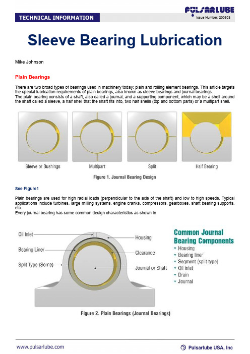
Sleeve Bearing Lubrication Mike JohnsonPlain BearingsThere are two broad types of bearings used in machinery today: plain and rolling element bearings. This article targets the special lubrication requirements of plain bearings, also known as sleeve bearings and journal bearings.The plain bearing consists of a shaft, also called a journal, and a supporting component, which may be a shell around the shaft called a sleeve, a half shell that the shaft fits into, two half shells (top and bottom parts) or a multipart shell.See Figure1Plain bearings are used for high radial loads (perpendicular to the axis of the shaft) and low to high speeds. Typical applications include turbines, large milling systems, engine cranks, compressors, gearboxes, shaft bearing supports, etc.Every journal bearing has some common design characteristics as shown inFigure 2.The components that are separated by the oil film in a plain bearing are the bearing liner and the shaft. The shaft is composed of high-quality, wear-resistant, structurally strong steel. The bearing liner may be made of a single layer or multiple layers, depending on the design features of the equipmentLubrication RegimeUnder normal operating conditions, the lubrication regime will be a hydrodynamic full-fluid film. A hydrodynamic film occurs when there is sufficient lubricant between the lubricated surfaces at the point of loading to form a fluid wedge that separates the sliding surfaces. In this state, the lubricated components do not touch each another, reducing friction and wear.This condition is represented by the equation ZN/P, where Z = viscosity, N = speed (rpm) and P = load. This equation is represented by Figure 4.The curve on this graph is called the Stribeck Curve. It is the classical representation of the relationship between speed, load and friction.Mixed film conditions occur when a loss of the film resulting in momentary contact between the two surfaces is apparent. This can occur in response to momentary variations in loading, called shock-loading, that can collapse the film, resulting in physical contact of opposing asperities.Another condition that can occur is boundary film lubrication. This is when the film that separates the surfaces undergoes significant loss resulting in a high load of metal-to-metal contact. This happens any time the relative motion of component surfaces are slow and no oil film is formed.Lubrication Needs of a Plain BearingOperating under proper speed, surface area, viscosity and oil volume, a plain bearing can support very heavy loads. The balance between these conditions is important. If the load or the speed changes, the lubricant viscosity must be adjusted to compensate for the change. There is no simple formula that is used to calculate the viscosity requirements for oil lubricated plain bearings, but the ZN/P formula demonstrates the results of complex calculations used to arrive at the proper clearance.Criteria to consider once you have identified the proper viscosity grade include oxidation stability, corrosion inhibition, wear protection, water and air separation properties, etc. Because plain bearings can be used in a variety of applications, there is no single set of criteria that should be used. Selection depends on the equipment design and operating conditions.Plain bearings are normally oil lubricated, but may be lubricated with grease for slow-speed equipment, particularly if they are subject to frequent starts and stops or the bearings may be physically difficult to reach.The type and amount of grease depends on continuous replenishment of the body of grease that is held within the dynamic clearances (empty spaces while the bearing is turning) in order to maintain effective lubricant condition and hydrodynamic lift. Equipment with poor sealing characteristics may require a heavier body of lubricant and more frequent replenishment cycles.Under manual (intermittent) relubrication, the volume and the frequency are influenced by operating conditions, grease quality and available time for the task. Grease selection begins with consideration of the oil to be used. Heavy oils are used to formulate greases used to manually lubricate plain bearings in high-duty service.After the proper viscosity oil has been selected, then the soap thickener, oxidation and rust characteristics, worked consistency properties, pumpability (for automatic systems) and load-bearing (EP/AW) properties are considered. For long intervals and very heavy loading, solid additives such as molybdenum disulfide or graphite may be incorporated. The solid additives would serve to mechanically prevent metal contact in mixed film and boundary lubrication conditions.The grease should be pumped into the bearing in front of the load zone and at the location of the grease grooves used for lubricant distribution (Figures 5 and 6).Figure 6Wear and Failure Modes in Plain BearingsThere are several factors that can wipe or damage a plain bearing surface. Abrasive wear is one of the most common. If the wear is caused by a hard particle rubbing between the lubricated surfaces, it is called three-body wear. Wear caused by an asperity on one surface cutting the other surface is called two-body abrasion.Wear can also result from insufficient volume of lubricant (starvation leading to boundary conditions), overheated lubricant (viscosity at operating temperature cannot support the load causing frictional heat and additional oil thinning), rough surfaces (asperities on the journal cause rubbing), imbalance (improper loading of the support element causing shock loading), journal eccentricity (egg-shaped journal causing rubbing on the high spots), and metal fatigue from improper metallurgy. Journal bearing wear can be effectively monitored by oil and ferrographic analysis.See Figure7The telltale indicators that may point to high wear conditions include high metallic particle counts (two levels above norm), darkened metal surfaces, blued metal surfaces and wear metals formed into spirals or platelets. As oils age and become contaminated with moisture or acidic oxidation compounds, we can see evidence of corrosion and metallic oxidation on stationary surfaces in the reservoir.。
达克(Dake)机械工业有限公司产品说明书:达克(Dake)机械工业有限公司型号4M机械杠杆螺纹压机

Dake CorporationPhone: 800.937.3253DAKE RATCHET LEVER ARBOR PRESSModel 4MINSTRUCTIONAL MANUALWARNING!Read and understand all instructions and responsibilities before operating. Failure to follow safety instructions and labels could result in serious injury.TABLE OF CONTENTSDAKE STANDARD LIMITED WARRANTY (2)RETURN & REFUND POLICY (4)DAKE STANDARD TERMS & CONDITIONS OF SALE (5)SPECIFICATIONS (6)SAFETY (6)HANDLE POSITION (7)OPERATION (7)MAINTENANCE (7)LUBRICATION (7)EXPLODED VIEW & PARTS LIST (8)EXPLODED PARTS VIEW (8)PARTS LIST (9)ORDERING INFORMATION (9)DAKE STANDARD LIMITED WARRANTYFinished MachinesDake warrants to the original purchaser the finished machine manufactured or distributed by it to be free from defects in material and workmanship under normal use and service within 1 year (12 months) from the delivery date to the end user.PartsDake warrants to the original purchaser the component part manufactured or distributed by it to be free from defects in material and workmanship under normal use and service within 30 days from the delivery date to the end user. The standard limited warranty includes the replacement of the defective component part at no cost to the end user.Sale of Service (Repairs)Dake warrants to the original purchaser the component part repaired by Dake Corporation at the manufacturing facility to be free from defects in material and workmanship under normal use and service within 90 days from the return date to the end user, as it pertains to the repair work completed. The standard limited warranty includes repair of the defective component part, at no cost to the end user. Warranty ProcessSubject to the conditions hereinafter set forth, the manufacturer will repair or replace any portion of the product that proves defective in materials or workmanship. The manufacturer retains the sole right and option, after inspection, to determine whether to repair or replace defective equipment, parts or components. The manufacturer will assume ownership of any defective parts replaced under this warranty.All requested warranty claims must be communicated to the distributor or representative responsible for the sale. Once communication has been initiated, the Warranty Representative at Dake Customer Service must be contacted for approval:Phone: (800) 937-3253Email: ****************************When contacting Dake, please have the following information readily available: - Model # - Serial # - Sales Order #Purchasers who notify Dake within the warranty period will be issued a Case number and/or a Return Material Authorization (RMA) number. If the item is to be returned per Dake’s request, the RMA number must be clearly written on the exterior packaging. Any item shipped to Dake without an RMA will not be processed.Warranty Exceptions:The following conditions are not applicable to the standard limited warranty:a) Part installation or machine service was not completed by a certified professional, and is not inaccordance with applicable local codes, ordinances and good trade practices.b) Defects or malfunctions resulting from improper installation or failure to operate or maintain theunit in accordance with the printed instructions provided.c) Defects or malfunctions resulting from abuse, accident, neglect or damage outside of prepaidfreight terms.d) Normal maintenance service or preventative maintenance, and the parts used in connection withsuch service.e) Units and parts which have been altered or repaired, other than by the manufacturer specificallyauthorized by the manufacturer.f) Alterations made to the machine that were not previously approved by the manufacturer, or thatare used for purposes other than the original design of the machine.RETURN & REFUND POLICYThank you for purchasing from Dake! If you are not entirely satisfied with your purchase, we are here to help.ReturnsAll Dake manufactured / distributed machines and parts include a 30-day return option. These policies are valid from the date of final shipment to the end user.To be eligible for a return, the item must be unused and in the same condition as received.All requested warranty claims must be communicated to the distributor or representative responsible for the sale. Once communication has been initiated, Dake Customer Service must be contacted for approval by the distributor or representative: Phone: (800) 937-3253 Email:****************************Once the return request has been approved by Customer Service, a representative will supply a Return Material Authorization (RMA) number. The returned item must have the provided RMA number clearly marked on the outside packaging. Any item received without an RMA number clearly visible on the packaging will not be processed. An RMA number can only be provided by the Dake Customer Service team and must be obtained prior to the return shipment.The item must be shipped and received back to Dake within 30 days from being issued the RMA number, or the return will be void and nonreturnable.RefundsOnce the item has been received and inspected for damages, a representative will notify the requestor referencing the provided RMA number.If the return is approved, a refund will be issued to the original method of payment, less a 20% restocking fee. The restocking fee may be waived if an order is placed at the time of return with like-value merchandise.Transportation costs are the responsibility of the end user and will not be credited upon return approval. Any item that is returned after the initial 30 days or has excessive/obvious use will not be considered for a full refund.DAKE STANDARD TERMS & CONDITIONS OF SALE All proposals and quotations for the original sale of our products are subject to the following terms and conditions:ACCEPTANCE OF ORDER: All orders are subject to acceptance by Dake at its main office in Grand Haven, Michigan.APPLICABLE LAWS: This quotation or acceptance shall be governed in all respects by the laws of the State of Michigan.CANCELLATION: We reserve the right to cancel and/or refuse to complete your order if, in our opinion, you have not established credit to promptly meet the payment terms of your order. Any cancellation from the Purchaser may be subject to a 10% cancellation fee for any of our standard machinery and/or component parts upon the discretion of Dake. All non-standard or special quotes will not be eligible for cancellation, nor returns.DELIVERY: The proposed shipment date is an estimate and is contingent upon causes beyond Dake’s control. Under no circumstances shall Dake have any liability for loss of use or for any direct or consequential damages resulting from delay. All shipments from the Dake facilities are F.O.B.FREIGHT CLAIM: Lost or damage freight claims must be submitted to Dake within thirty (30) days of shipment from Dake’s facility. If shipment for order was set up by the Purchaser, Dake is not liable to handle the freight claims.PERMITS AND COMPLIANCE: Dake shall not be responsible for obtaining any permits, inspections, certifications, or licenses required for the installation or use of the equipment. Dake makes no promise or representation that the equipment or any services to be furnished by Dake will conform to any federal, state, or local laws, ordinances, regulations, codes or standards.PRICES: Unless otherwise agreed to in writing, all prices are F.O.B. from our plants in Grand Haven, Michigan, Grand Prairie, Texas, and Riverside, CA. In any event, the quoted prices for component parts become invalid ten (10) days after date of quotation, and machinery may become invalid sixty (60) days after date of quotation. Unless otherwise specified in Dake’s quotation, installation services and final on-site adjustments are not included in the quotation.TAXES: Prices do not include taxes. If any sales, use or similar tax is payable to Dake in connection with any transaction or part thereof between the Purchaser and Dake with respect to goods delivered, the Purchaser will, upon demand, pay to Dake the amount of any such tax. If you are tax exempt, please include your exemption document when submitting your order.TERMS OF PAYMENT: Terms of payment are as stated in Dake’s quotation subject to credit approval by our home office. Dake will invoice Purchaser when the equipment is completed and ready for shipment. Payment terms run from invoice date. Purchaser may be required to issue a down payment before production of order, at the discretion of Dake Accounting. For credit card purchases, a 2% processing fee may be applicable to the order. The following states are exempt from the 2% processing fee: CA, CO, KS, OK, TX, FL, NY, CT, MA, and ME.WARRANTY: If, within a period of one (1) year from date of shipment of the original order, any part of any equipment sold by Dake is defective in material or workmanship and is so found after inspection by Dake, it will be replaced or repaired at the option of Dake, providing the equipment has been given normal and proper usage and is still the property of the original Purchaser. Purchased components such as Micro Drop mist system or the like, installed as a part of Dake equipment are warranted only to the extent of the original Manufacturer’s warranty. Dake is not responsible for any service work performed unless authorized in advance.THE FOREGOING WARRANTY IS EXCLUSIVE AND IN LIEU OF ALL OTHER WARRANTIES WHETHER WRITTEN, ORAL, OR IMPLIED (INCLUDING ANY WARRANTY OF MERCHANTABILITY OR FITNESS FOR PARTICULAR PURPOSE). UNDER NO CIRCUMSTANCES SHALL DAKE BE LIABLE FOR ANY INCIDENTAL OR CONSEQUENTIAL DAMAGES.SPECIFICATIONSModel 4M Largest arbor 5-1/4” Number 902006 Capacity over table 26” Capacity 5 tons Capacity over table plate 24-1/2” Leverage ration 55:1 Base length21-1/2” Ram size2 x 2 x 23” Base width24” Max diameter work 20” Height 58” Throat 10” Weight1045 lbsSAFETYThis is the safety alert symbol. When you see this symbol on your press be alert to the potential for personal injury.Employer is responsible to perform a hazard/PPE assessment before work activity.Follow recommended precautions and safe operating practices. Carefully read all safetymessages in theseinstructions and on yourpress safety signs.Keepsafety labels in goodcondition. Replace missing ordamaged safety labels.This machine is intended tobe operated by one person.This person should beconscious of the press rammovement not only forthemselves but also forpersons in the immediatearea of the machine.Under no circumstancesincrease the leverage ratioof the press by using alonger handle or by placinga pipe over the handle.Never hammer on top of theram.HANDLE POSITIONCAUTION: NEVER PULL THE PRESS HANDLE PAST THE HORIZONTAL POSITION!To avoid personal injury and damaging the press only pull until the handle is horizontal, then return the handle back up as far as it allows before bringing the handle back down. This ensures that the pawl fully engages with the gear teeth to prevent tooth damage and gear slippage that can cause harm to the machine and worker. Examples above show the ideal minimum and maximum handle positions.OPERATIONHandwheel: The handwheel (item 15) can be turned to raise or lower the ram to and from the workpiece without exerting force on the workpiece.Handle: The handle (item 23) can be used to lower the ram to exert force onto the workpiece. See safety instructions for more information on handle position.MAINTENANCELUBRICATION•Keep all working parts of the press well-oiled for easier operation.•Keep a light film of oil over the entire surface of the ram to prevent rust.EXPLODED VIEW & PARTS LIST EXPLODED PARTS VIEWPARTS LISTItem Part Name Part Number Qty1 Frame 295 12 Mandrel Catcher 254 13 Table Pinion 271 14 Table Pinion Shaft 291 15 Table Crank 270 16 Table Pawl Handle 266 17 Table Pawl Shaft 287 18 Table Pawl 265 19 Spring (1/2” x 2”) 302436 110 Table Plate Assembly 701227 111 Hex Cap Screw (1/2”-13 x 1-3/4”) 43350 412 Label – Made in U.S.A. 76936 113 Ram Cap 296 114 Ram Cap Shim (.015”) 252 615 Handwheel 257 116 Ram Cap Shim (.008”) 251 217 Hex Cap Screw (3/8”-16 x 2”) 43333 118 Ram 253 119 Table 262 120 Hand Brake Stud 223A 121 Handbrake Clamp 215 122 Handbrake 214 223 Handle 283 124 Hex Jam Nut (1/2”-13) 43940 125 Flat Washer (1/2”) 43634 126 Compound Rest Pin 280 127 Headless Set Screw (1/2”-13 x 1-1/2”) 43608 128 Pawl 297 129 Spindle 256 130 Table Stud 282 231 Table Washer 279 232 Table Spring 281 233 Hex Cap Screw 53759 234 Table Clamp 267 135 Hex Nut (1-8) 43922 236 Headless Set Screw (3/8”-16 x 5/8”) 43589 437 Lever Weight 258 138 Pawl Pin 255 139 Retaining Ring 67955 140 Warning Label – Pinch Point 87130 141 Warning Label – Tipping 79979 142 Warning Label – Ganged 300168 1Please contact factory for current prices.ORDERING INFORMATIONParts are available for direct purchase from Dake or through a distributor. When placing a parts order, you will need to provide the part number, name of part, and model number. All parts shipped F.O.B. Factory in Grand Haven, MI.。
英文版焊线机说明书

EDP-No.
EDP-No.
Vertical grinding motor:
Nominal capacity: Connection voltage: Nominal current: Number of revolutions: Grinding wheel: 0,25 220 1,8 2880 0900-0105 kW V A min-1 EDP-No.
Dimensions (with carrier), abt.:
Weight (with carrier), abt.: Year of construction:
Illuminated magnifier:
Fluorescent tube:
230 V / 50 Hz 0550-0009 4W 0550-0011
8 8.1 8.2 9 9.1 9.1.1 ends
wire
9.2 9.3 9.4 9.5 9.6 9.7 9.8 10 10.1 10.2 10.2.4 10.2.5 10.2.6 10.2.7 11 12
../ 4
- 4 -
1.
Foreword
These operating instructions are designated to familiarize the user with the machine and its' designated use. The instruction manual contains important information on how to operate the machine safely, properly and most efficiently. Observing these instructions helps to avoid danger, to reduce repair costs and downtimes and to increase the reliability and life of the machine. The user has to supplement the instruction manual by the respective national rules and regulations for accident prevention and environmental protection. The operating instructions must always be available wherever the machine is in use. These operating instructions must be read and applied by any person in charge of carrying out work with or on the machine such as: transport, operation, including setting up, trouble-shooting in the course of work or upkeep, as well as maintenance such as servicing, inspection and repair. In addition to the operating instructions and to the mandatory rules and regulations for accident prevention in the country and place of use of the machine, the generally recognized technical rules for safe and proper working must also be observed.
LC型泵安装使用说明书-中英文

LC型泵Type LC Pump安装使用说明书Installation and Operation ManualC a u t i o n■请仔细阅读本说明书,理解各项内容,以便能正确安装、运行操作和保养维护等。
Please read this manual carefully and understand all the contents in it for correct installation, operation andmaintenance.■本说明书应保存在实际最终使用人的手中。
This manual should be kept in the hands of the actual end users.■本产品技术规范可能发生变化,恕不另行通知。
The technical specification of this product may change without notice.襄樊525泵业有限公司Xiangfan 525 Pump Industry Co., Ltd.目录Contents 1. 适用范围Scope of application2.泵的结构The Structure of the pump.3.开箱检查Unpacking and checking4.泵的安装Installation of the pump5.泵的运行Startup and operation of the pump 6.泵的维护Maintenance of the pump7.泵的拆卸Disassembling8.泵的装配Assembling9.故障原因及解决办法Possible troubleshooting and solutions 10.常用备件Spare parts1.适用范围Scope of applicationLC、LC——B系列泵是我公司引进的法国日蒙施乃德(JS)公司制造许可证技术,奥特桑伯尔(HS)公司耐腐蚀耐磨蚀泵用材料冶炼铸造技术。
车床 CZ系列C型说明书(机械部分)英文版
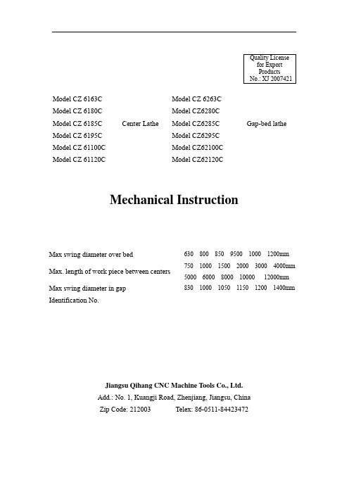
QualityLicensefor ExportProductsNo.: XJ 2007421Model CZ 6163C Model CZ 6263CModel CZ 6180C Model CZ6280CModel CZ 6185C Center Lathe Model CZ6285C Gap-bed latheModel CZ 6195C Model CZ6295CModel CZ 61100C Model CZ62100CModel CZ 61120C Model CZ62120CMechanical InstructionMax swing diameter over bed 630 800 850 9500 1000 1200mmMax. length of work piece between centers 750 1000 1500 2000 3000 4000mm 5000 6000 8000 10000 12000mmMax swing diameter in gapIdentification No.830 1000 1050 1150 1200 1400mmJiangsu Qihang CNC Machine Tools Co., Ltd.Add.: No. 1, Kuangji Road, Zhenjiang, Jiangsu, ChinaZip Code: 212003 Telex: 86-0511-********ContentI. Notice on use of the machine tool and safety measures thereof (2)II. Main purposes of the machine tool (8)III. Main technical parameters of the machine tool (8)IV. Transmission system of the machine tool and its structure (12)V. Lubrication and cooling of the machine tool (20)VI. Manipulation, adjustment and safety maintenance of the machine tool (21)VII. Conveying, installation and commissioning of the machine tool (37)VIII. Distribution diagram and list of rolling bearings of the machine tool (38)Ⅸ. Catalog and working diagram of wearing parts of the machine tool (48)X. Jointing techniques for bed, lead screw and feed rod (55)I. Notice on use of the machine tool and safety measures thereof1. Notice on operation1). The operator must accept skill trainings before operating on the machine.2). The operator shall refer to Instructions on Mechanical and Electrical Safety before using the machine tool for the first time, sufficiently lubricating each part as required and activating the machine tool only after having had a full understanding of positions and purposes of each handle and button.3). Before activating the machine during each shift, it is required to check the cleanness of various lubricating surfaces, sufficiency of lubricants as well as fastness of screw-nails on various places in addition to running each part idly for a short period.4). In case the machine tool is to be restarted after a long stop, it shall first idle for a certain period of time and shall be put into production only after all parts have been confirmed to be in a normal state.5). In case the spindle and gears in the feeding box are rotating, no change to rotational speed or feeds shall be made. Where any changes are required, it is imperative to stop the operation and place each gear-shift handle at specified positions in accordance with the label plate on the machine tool.6). When the tool post is moving at a fast pace, the direction of such a rapid move shall first be determined before pressing down the fast forward button.7). When utilizing the tailstock to support and hold the work-piece, the locking nuts between the bed and the tailstock as well as the locking handle of the tailstock sleeve shall be fastened.8). When adopting centers for processing, please pour oil onto centers and stop the machine immediately upon discovery of an over-heating center. It is not allowed to operate with damaged centers.9). Where steady rest and traveling rest are used for supporting the turning of work-piece, the contacting place between the support and the work-piece shall be lubricated.10). The voltage of the grid shall be kept in the range of AC380±15% so as to ensure normal operation.2. Maintenance and proper use1). It is not allowed to place any articles tend to damage the machine tool on the finishing surface or each guide-way surface of the machine tool.2). It is required to add oil, change oil and check the oil inlet/outlet within the spindlebox according to the lubrication diagram on a regular basis so as to prevent the oil inlet/outlet from clogging.3). The lubricant shall be replaced once within one month after the initial use of the machine tool and since then it shall be replaced every two months.4). When replacing the lubricant, strictly filter and clean the same so as to prevent bearings and gears from damaging.5). When the work is finished, clean the guide-way surface and apply an oil coating thereto.(6) The machine tool shall be kept working under good working conditions. Such situations as abnormal noises, smokes, heats or damages shall be reported to relevant personnel in time upon discovery and shall be inspected after the machine is off.(7) The tightness degree of the triangular belt shall be inspected on a regular basis so as to maintain a good working status.(8) The maintenance of the machine tool shall be carried out on the prerequisite that the machine is off.(9) Please refer to drawings of relevant parts before carrying out maintenance or repair.(10) The repairman eligible to repair this machine tool shall have a clear understanding of its structure and obtain mechanical and electrical knowledge to a certain degree.3. Safety knowledge(1) Concentrate on works and always maintain safety consciousness. It is forbidden to smoke while working or operate the machine tool when drunk.(2) When operating the machine tool, no such accessories as tie, watch, ring and diamond is allowed to wear. People will get hurt if come in contact with rotating parts, so do not get close to the rotating head of the spindle in operation or hold the rotating part.(3) Various kinds of spanners, tools and parts shall be kept away from the spindle, work station or moving parts of the machine tool.(4) The ground around the machine tool shall always keep clean. No iron scraps shall accumulate on the ground or machine oil and liquid coolant spill over onto the ground, thus influencing the machine tool.(5) When the machine tool is running, do not put hands at somewhere close to the tool or moving devices.(6) Before running the machine tool, it is required to grip the work-piece and the clamp; otherwise, the machine tool shall not be started up.(7) The machine tool has to stop running when changing the tool.(8) The guard door of the change-gear device is not allowed to be open during work, soas to prevent abrupt power failure which might bring avoidable accidents.(9) The operator shall keep in mind positions of all emergency stop buttons, so as to be ready for any eventualities.(10) The tailstock is equipped with an unloading devise, so please be careful when pulling it.(11) The power supply must be cut off when examining and repairing the machine tool.(12) People getting an electrical shock of high voltage may die. Thus, person in charge of the implementation of maintenance and repair of electric appliances shall limit to those who have acquired knowledge on circuits of the machine tool and have accepted trainings on safety issues of electric appliances. The work shall be carried out only when the main power source has been cut off and an indication of “in operation” has been marked.(13) The cutting fluid, machine oil and cutting powders spilled over on the ground might hurt people by letting them fall over themselves or hit somewhere. Cut off the power of the machine and clean the interior of the machine and surrounding areas before operating the same. During installation and operation, it is required to wear safety helmet and protective shoes.(14) If any tools or work-pieces get stuck by the machine tool which activates abruptly, the broken and damaged ones might fly off and seriously hurt people. It is strongly required to cut off the power before carrying out maintenance and inspection.(15) In case the spindle is rotating, no change to rotational speed or feeds shall be made. When using three-jaw chuck and four-jaw chuck, their specification shall not exceed Ф630mm. Where four-jaw chuck of Ф4000mm is used, the rotational speed of the spindle shall not go beyond 380rpm. The Specification mainly aims at equipping the operator with a preliminary knowledge of the machine tool’s performance, proper operation, simple adjustment and maintenance. For profounder understanding and special requirement, please contact the After-sale Service Department of our company.Fig.1: Profile drawing of the machine toolFig.1: Profile drawing of the machine tool (5M 6M)Fig.1: Profile drawing of the machine tool (8M 10M 12M)II. Main purposes of the machine toolThis machine tool is capable of various coarse and fine turning of ferrous metal, nonferrous metal and non-metal work-pieces, such as turning of inner and outer cylindrical surfaces, conical surface and other surfaces of revolution. It is also capable of turning of end faces and various metric, inch, module and pitch threads in common use as well as multiple-threads. Moreover, it enables drilling, reaming, oil channeling and so on thereon. The dimensional accuracy of work-pieces processed on this machine tool can reach IT7 level, with its roundness error being no larger than 0.01 and its cylindricity on 300 mm length being no larger than 0.03. Its surface roughness can reach 1.6 (for standard sample piece).III. Main technical parameters of the machine tool310mm CZ6163C CZ6263C 400mm CZ6180C CZ6280C 425mm CZ6185C CZ6285C 475mm CZ6195C CZ6295C 500mm CZ61100C CZ62100C Central Height600mm CZ61120CCZ62120C 630mm CZ6163C CZ6263C 800mm CZ6180C CZ6280C 850mm CZ6185C CZ6285C 950mm CZ6195C CZ6295C 1000mm CZ61100C CZ62100C Max. Swing Diameter over Bed1200mm CZ61120CCZ62120C 345mm CZ6163C CZ6263C 485mm CZ6180C CZ6280C 535mm CZ6185C CZ6285C 635mm CZ6195C CZ6295C 685mm CZ61100C CZ62100C Max. Swing Diameter over Tool Post800mm CZ61120CCZ62120C830mm CZ6263C Max. Swing Diameter over Gap (Saddle Machine tool)l000mmCZ6280C1050mm CZ6285C1150mm CZ6295C1200mm CZ62100C1400mm CZ62120CMax. Turning Length 450/700/1200/1600/2600/3600/4600/560/7600/9600/11600mmWidth of Bed Guide-way 550mmSpindle Taper 1:16Taper of Spindle Center Sleeve No.6 (Morse)Spindle Bore 105mmRotational Speed Step/RangeClockwise 18 Steps 14-750 r/minof Spindle Counterclockwise9 Steps 21-857 r/min Kinds and Ranges of FeedsBasic FeedsLongitudinal 32 Kinds 0.10-1.42 mm/rCross 32 Kinds 0.03-0.45 mm/r Fine FeedsLongitudinal 8 Kinds 0.048-0.089 mm/rCross 8 Kinds 0.015-0.028 mm/r Increased FeedsLongitudinal 32 Kinds 1.52-22.8 mm/rCross 32 Kinds 0.48-7.2 mm/r Kinds and Ranges of ScrewingMetric Thread 54 Kinds 1-240Inch Thread 37 Kinds l-28 threads/inchModule Thread 45 Kinds 0.5~60mmPitch Thread 27 Kinds l-30 threads/inchMax. Travel of Top Slide 230mmMax. Travel of Cross Slide 400mmDistance from Spindle32mmCenterline to Tool BearingSurfaceCross-Section of Tool 30×30mmDiameter of Tailstock Spindle Ф100mm or Ф120mm Taper of Tailstock Spindle No.5 or 6 (Morse)Max. Travel of Tailstock Spindle200mm Y160M-4Power 11KW Model of Main MotorRotational Speed1460 r/minYS5634 Power0.12 KW or 0.18 KW Model of Rapidly-Traveling Motor of ApronRotational Speed1400 r/minLongitudinal 6 m/minRapid Traveling Speed of Apron Cross 2 m/min AB-25 or AB-100Power 0.09 KW or 0.12 KW Model of Cooling MotorFlow25 L/min or 100 L/min1000 kg CZ6163C CZ6263C Max. Weight between Two Centers1200 kgCZ6180CCZ6280C and aboveLength of BedExternal Dimensions of Machine Tool(L×W×H)Weight of Machine Tool (approximately, t)750 2702×1276×1260 3.8 1000 2952×1276×1260 4.0 1500 3452×1276×1260 4.5 2000 3952×1276×1260 5.0 3000 4952×1276×1260 5.5 4000 5952×1276×1260 6.5 5000 6952×1276×1260 9 6000 7952×1276×1260 10 8000 9952×1276×1260 11.5 10000 11952×1276×1260 13 12000 13952×1276×126014.5F i g .2: D i a g r a m o f t h e m a c h i n e t o o l t r a n s m i s s i o n s y s t e mn =1460 r /m i nIV. Transmission system of the machine tool and its structure(I) Machine tool transmission systemShown in Fig.2 is the machine tool transmission system.1. Main transmission systemThe work-piece shall be clamped on the chuck or between two centers. The motor drives the spindle via transmission of belts and gears so as to rotate the work-piece.There are two routes for its rotational transmission in clockwise direction, having been divided into 18 steps.Low-speed portion: (14-190 r/min)Main motor →Shaft I →Shaft II →Shaft III →Shaft IV →Shaft V →Shaft VI (Spindle) High-speed portion: (230-750 r/min)Main motor →Shaft I →Shaft II →Shaft III →Shaft V →Shaft VI (Spindle)There are also two routes for its rotational transmission in counterclockwise direction, having been divided into 9 steps.Main motor →Shaft I →Shaft VII →Shaft II →Shaft III→Shaft IV →Shaft V →Shaft VI Shaft V→ Shaft VI2. Feeding transmission systemThe feeding motion of the machine tool is enabled by the feeding box and apron. Its transmission route is: Headstock’s Shaft III or Shaft V →Shaft VIII →Shaft IX (or Shaft VIII →Shaft X →Shaft IX) →Change-Gear Bracket →Feeding box →Apron. The longitudinal, cross, clockwise and counterclockwise feeding motion of the machine tool can be realized via change of directions within the apron.3. Rapid movement of the tool carriage of the machine toolThe rapid movement of the tool carriage of the machine tool is realized by the rapidly-traveling motor installed on the apron.(II) Explanation on the structure of main subassemblies1. BedThe guide-ways of the bed include two planar ones and two rhombic ones. The front rhombic guide-way and the rear planar guide-way are used by the tool carriage, while the rest are for the tailstock and steady rest.2. Spindle boxThe rotational motion of the spindle is enabled by the main motor via the action of triangular belt and gear shift, having been divided into 18 steps. Its rotational speed ranges from 14 r/min to 750 r/min.A fiction clutch is installed on Shaft I of the spindle box so as to protect the transmission component of the machine tool as well as realize clockwise and counterclockwise rotation of the spindle in a convenient way without stopping the rotation of the main motor.The Shaft III and Shaft V of the spindle box lie in the same centerline and they can be joined together directly via internal gear 18 and gear 19 under the condition that gears 14, 15, 16 and 17 are disengaged in respect to each other (see Fig.2), thus realizing branch transmission of spindle rotation.The front bearings of the spindle are adjustable double-row short centripetal cylindrical roller bearings while the rear ones are single-row tapered roller bearings. In addition, single-direction thrust ball bearings are installed on the rear end of the spindle so as to bear axial load.The spindle box is an enclosed box which adopts splash lubrication.The maximum tolerable torque at gears of the spindle box is 1500N m.3. Feeding boxThe feeding box is a two-shaft sliding gear mechanism made up of three parts, namely, basic group, multiplication group and inch/mm conversion group.The feeding box is an enclosed box which adopts centralized lubrication by manual oil-pump.Operating relevant handles while shifting change-gears as per the upper pitch of the feeding box and the indication on the label plate of feeds may acquire different pitches of various screw threads and feeds.4. Apron (See Fig.3)It is mainly used to transfer the motion of the feed rod or lead screw to the tool post so as to provide the tool post with power-driven feeds in cross/longitudinal direction or screwing.In order to avoid interferences of power-driven feeds with the motion of screwing mechanism, an interlocking mechanism is installed in the apron for preventing these two motions from happening simultaneously. Also provided in the apron is an out-of-gear worm security device to avoid extremely heavy loads of the feed mechanism. In order to reduce the labor intensity of the operator, the apron is equipped with a rapidly-traveling motor and amechanical/electrical interlocking stopper to ensure that the motor won’t be activated during the process of power-driven feeds.5. Tool post (See Fig.4)The tool post can not only be driven in longitudinal direction along the bed and in cross direction along the cross slide but also be operated manually or traveling rapidly. But the compound rest can only be operated manually.The tool post swivel (1) can rotate 60° in left and right directions respectively in relation to the tool carriage (2) so as to facilitate the turning of conical parts.For machine tools of models above CZ6180C, the quadrate base of the cross slide can be properly adjusted in cross direction along the slide so as to broaden the processing scope of various parts.6. Tailstock (See Fig.5)The tailstock is tightly fixed onto the bed by the clamping plate (1) and this can be realized by rotating the locking handle (6) or nuts (7). For turning of long but less tapered work-pieces, the upper body of the tailstock (4) shall move crossly on the tailstock base (5) by bolts (2) and nuts (3) for the sake of center shift.The movement of the tailstock sleeve (8) is realized by the hand-wheel (9) while its locking and loosening are realized by the handle (10).The tailstock base (5) is equipped with an unloading device for facilitating the movement of the tailstock. It is made up of a disc spring (11), a rolling bearing (12) and subassemblies (13), (14) and (15). The screw-nail (16) is used as an axial limit.7. Steady rest (See Fig.6)The steady rest is used as a support when processing slender shaft components so as to prevent any bending caused by cutting force. The clamping scope is Ф20-145mm for CZ6163C or Ф20-185mm or Ф300mm for series above CZ6180C. It can also be used for processing parts with large length under circumstances where using the tailstock as the support is inappropriate.The traveling rest is a steady rest moving alongside with the tool post while fixed on the carriage. The clamping scope is Ф20-105mm for CZ6163C or Ф20-135mm or Ф180mm for series above CZ6180C.Fig.3: ApronV. Lubrication and cooling of the machine tool1. The spindle box of the machine tool adopts splash lubrication while the feeding box and apron adopt centralized lubrication by manual oil-pump. The rest utilize manual lubrication by oiling. For specific parts to be lubricated and the requirement thereof, please refer to the indications about machine tool lubrication on the label plate. Since part of the lubricant cannot return to the apron after having reached guide-ways of the bed, the apron shall be refilled with some lubricant according to specific situations so as to ensure that the surface of the lubricant is maintained at a certain level within the apron. The lubricant shall be filled to a depth of 80 mm in the spindle box where the oil scale for CZ6163C is placed. The lubricant shall be filled to a position reaching half of the orifice for series above CZ6180C. The feedbox needs 1.0L oil. The above-mentioned machines and components normally require HJ30 oil.2. The liquid coolant for the machine tool shall be replaced every three months in case of processing of casting and every six months in case of processing of steel parts. The coolant shall be replaced immediately upon deterioration and the water tank shall also be cleaned in time therewith, where the scrap iron shall be cleared by the magnet.3. The cooling system of the machine tool (See Fig.7).VI. Manipulation, adjustment and safety maintenance of themachine tool(I). Manipulation of the machine tool1. For information on positions of various manipulation handles of this machine tool, please refer to Fig.8, while for information on their names, please refer to Sheet2.2. Manipulating method of the main transmission systemThe rotational speed of the spindle is achieved by switching handles (1), (2) and (5), where the handle (5) has three positions marked as 1:1, 1:4 and 1:16, respectively. The handle (5) enables low-speed transmission at the position of 1:4 or 1:16 and can obtain a rotational speed of step 12 in clockwise direction and another of step 6 in counterclockwise direction when in cooperation with handles (1) and (2). In case a high-speed transmission is required, please turn the handle (5) to the position of 1:1 where a rotational speed of step 6 in clockwise direction and another of step 3 in counterclockwise direction can be attained in cooperation with handles (1) and (2).The manipulation handle (21) or (28) has three positions, where the spindle rotates in clockwise direction when the handle is lifted up and rotates in counterclockwise direction when the handle is pressed down. The spindle stops rotation when the handle is place at the middle position.The machine tool must be stopped when the gear shift handle is in operation; otherwise transmission gears might be damaged.3. Operating method of the feeding systemThe feeding motion is realized through proper switch of handles (3) and (4) of the headstock and handles (15), (16), (17) and (20) on the feeding box. The handles shall be placed at proper positions as indicated on the label plate above them.(1) The handle (3) is a handle for left/right threads. Aligning it with the mark□ can produce right-hand threads and feeds in clockwise direction; while aligning it with the mark□can produce left-hand threads and feeds in counterclockwise direction. No feeding motion will be generated when it is placed at the middle position.(2) The handle (4) is a standard handle for pitch enlargement. Aligning it with the mark□1/1 can attain basic pitch and basic feeds; while aligning it with the mark□ x/1 can attain enlarged pitch and increased feeds. No feeding motion will be generated when it is placed at the middle position.F i g .8: P o s i t i o n D i s t r i b u t i o n D i a g r a m o f M a n i p u l a t i o n H a n d l e s o f t h e M a c h i n e T o o lF i g .8: P o s i t i o n D i s t r i b u t i o n D i a g r a m o f M a n i p u l a t i o n H a n d l e s o f t h e M a c h i n e T o o l (5M 6M )F i g .8: P o s i t i o n D i s t r i b u t i o n D i a g r a m o f M a n i p u l a t i o n H a n d l e s o f t h e M a c h i n e T o o l (8M 10M 12M )Name Sheet of Various Manipulation Handles of the Machine Tool Sheet 2Numerals in DistributionDiagram of VariousManipulation Handles ofthe Machine ToolNames1 Gear Shift Handle for Changing the Rotational Speed of the Spindle of the Machine Tool2 Gear Shift Handle for Changing the Rotational Speed of the Spindle of the Machine Tool3 Handle for Left/Right Threads4 Standard Handle for Pitch Enlargement5 1:1, 1:4, 1:16 Gear Shift Handle for Changing the Rotational Speed of the Spindle6 Button for Starting/Stopping the Machine Tool7 Handle for Moving the Cross Slide8 Handle for Moving the Top Slide9 Handle for Clamping/Loosening the Quadrate Tool Post10 On/Off Button for the Coolant11 Button for Rapidly Moving the Slide12 Handle for Locking/Loosening the Spindle of the Tailstock13 Hand-wheel for Moving the Spindle of the Tailstock14 Handle for Locking/Loosening the Tailstock15 Handle for Inch/mm Conversion of Threads16 Hand-wheel for Speed Adjustment of the Basic Group17 Hand-wheel for Speed Adjustment of the Multiplication Group19 Handle for Lubricating the Feeding Box by Manual Oil-Pump20 Handle for Connecting the Lead Screw and the Feed Rod21 Handle for Manipulating the Spindle Rotation in Clockwise/Counterclockwise Direction22 Hand-wheel for Moving the Slide in Longitudinal Direction23 Hand-wheel for Switching Feeds in Clockwise/Counterclockwise Direction24 Handle for Lubricating the Apron by Manual Oil-Pump25 Handle for Feeds in Longitudinal/Cross Direction26 Handle for Manipulating Slit Nuts27 Handle for Manipulating the Out-of-Gear Worm28 Handle for Manipulating the Spindle Rotation in Clockwise/Counterclockwise Direction(3) The handle (15) on the feeding box is a handle for inch/mm conversion of threads.Placing the handle (15) at means cutting of metric and module threads in addition togaining feeds; while at means cutting of inch and pitch threads.The handle (16) is a manipulation hand-wheel for the basic group, and there are 1-8 positions indicated on its label. By aligning it with points indicated on the guard ring respectively, the pitches and feeds can be switched in sequence. In order to change the position of the hand-wheel (16), it is required to pull out the same and rotate it to the desired position before pushing it in. The hand-wheel can rotate in both clockwise and counterclockwise directions during manipulation.The handle (17) is a shift handle for the multiplication group, bearing I-IV positions. By aligning the Roman numerals with the L above them respectively, multiplied pitches and feeds can be attained. The handle (17) can rotate in both clockwise and counterclockwise directions during manipulation.The handle (20) is a handle for switching between the lead screw and the feed rod.Placing the handle (20) at will enable feed-rod transmission so as to realizepower-driven feeds of the tool post; while placing it at will enable lead screw transmission, thus processing various threads.The above-mentioned handles shall work in proper cooperation with other and with gears in Fig.9 as per locations indicated on the label plate of pitches and feeds so as to attain the desired feeding motion.(4) When processing threads with a dimension of 19 threads /inch, change the ratio of gears as required in Fig.12 and, at the same time, place the hand-wheel (16) at the position of numeral “7” and the hand-wheel (17) at “I”.4. Control of tool post motions(1) When cutting the threads, the movement of the tool post shall be controlled by thehandle for slit nuts (26). Press down the handle (26) to the position of , then the apron will be driven directly by the lead screw. The carriage will stop moving when the handle is lifted up.(2) Power-driven feeds of the tool post in longitudinal/cross direction shall be driven by the feed rod and controlled by handles (23), (25) and (27). The handle (23) is a handle for switching feeds in clockwise/counterclockwise direction. Feeds in clockwise direction can be achieved by aligning the mark indicated on the label of the handle (23) with the right T; while those in counterclockwise direction can be achieved by aligning the markwith the right T.The handle (25) is a handle for switching feeds in longitudinal/cross direction. Feeds orrapid movement in longitudinal direction can be achieved by aligning the mark indicated on its label with the upper T; while those in cross direction can be achieved byaligning the mark with the upper T.The handle (27) is a handle for controlling the out-of-gear worm. When lifting up the handle, the worm engages with the worm wheel, thus realizing power-driven feeds in the direction matching with the handle (25). When pressing down the handle, the worm disengages with the worm wheel so as to stop power-driven feeds. During the process of power-driven feeds, the handle (27) will fall off automatically when the resistance against feeds of the tool post in longitudinal direction reaches 5830N, thus serving as a security mechanism.(3) The manual control of the tool post can be realized via hand-wheel (22) and (7). Both hand-wheels are equippted with reading devices where an illuminating device is provided above the reading device of the hand-wheel (22). The hand-wheel (22) can control the manual longitudinal motion of the tool post in clockwise/counterclockwise direction; while the hand-wheel (7) can control the manual cross motion of the tool post in forward/backward direction.(4) In order to reduce the labor intensity of the operator, this machine tool is equipped with a rapidly-traveling device, which can be realized via cooperation by the button box (11)and the handle (25). When the handle (25) is placed at the position of , activating the button to connect with the left button will enable the carriage to move rapidly towards left; while activating the button to connect with the right button will enable the carriage to moverapidly towards right. When the handle (25) is placed at the position of , activating the button to connect with the left button will enable the tool post to move rapidly in forward direction; while activating the button to connect with the right button will enable the tool post to move rapidly in backward direction. The rapid motor can only be activated when the button is pressed down, and it will stop rapid movement as soon as the button is loosened. When the rapid motor is activated, the handle (27) must be put down. If the handle (27) is at “connected” position (namely, if the power-driven feeds are activated), then activating the button will not generate rapid movement (An interlocking device for power-driven feeds and rapid movement is provided in the apron).(5) In order to prevent lead screw and feed rod from interfering with each other and thus causing damages to various parts, an interlocking mechanism is provided in the apron. When the handle (25) stays at the middle position, the handle for slit nuts (26) can be connected in downward direction and if the handle (25) stays elsewhere, the handle for slit nuts (26) is unable to be connected. Also, when the handle for slit nuts (26) is connected in downward direction, then the handle (25) is unable to turn to other positions.(6) In order to prevent feeds and rapid motions from interfering with each other and thus causing damages to various parts, another interlocking security mechanism is also provided in。
数控加工中心机械说明书 中英文

目录Catalog AI安全注意事项Safety precautions………………………………………II安全操作指导原则Safe operating guide…………………………………III★★★重要说明★★★★★★Important★★★……………………………IV安装须知Installation notice……………………………………V环保须知Environmental notice………………………………VI前言Foreword………………………………………………VII第一次启动前注意事项Notice before the first time starting………………..VIII目录Catalog B………………………………….使用说明书 Operating instructionOperating manual电气说明书 electrical operating instructionElectrical operating manual机械使用说明书Mechanical operating instructionMechanical operating manualI安全注意事项 Safety precautions在安装、运行、编程、维护、检修之前,请务必熟读机械制造商所刊行的规格书、本说明书、相关说明书、附属文件,然后正确使用。
请在熟悉了本装置相关知识、安全信息及注意事项之后再使用。
Before installing, operating, programming, maintaining, and overhauling, please be sure to read up on all related specification, instruction, manual book, and files.Before using this machine, please be familiar with all related knowledge, safety information, and precautions.在本说明书中,将安全注意事项的等级分为“危险”、“警告”、“注意”。
英特诺物流机械操作说明书 - DriveControl 20 DriveControl 54 Dri

INSPIRED BY EFFICIENCY操作说明书Interroll DriveControl DriveControl 20DriveControl 54DriveControl 2048制造商地址INTERROLL(Suzhou) Co. LTD.NO. 16 Huipu RoadSuzhou Industrial ParkJiangsu Province, P.R.ChinaZip code:215126英特诺物流机械(苏州)有限公司中国江苏苏州工业园区惠浦路16号;邮编215126内容我们力求信息的准确性,及时性和完整性,并精心准备了本文档中的内容。
无论如何,错误和更改均明确保留。
版权/知识产权文本,图片,图形等及其排列受版权保护和其他保护法的保护。
禁止以任何形式复制,更改,传播或出版本文档的部分或全部内容。
本文档仅用于提供信息和预期用途,无权复制有问题的产品。
本文档中包含的所有标记(受保护的标记,例如徽标和商业名称)均为Interroll AG,CH或第三方的财产,未经事先书面许可,不得使用,复制或分发。
在线版本 - 仅适用于彩色打印!目录1 关于本文档 7 1.1 本文档中的警告提示 81.2 符号 92 与安全相关的信息 10 2.1 最新技术水平 10 2.2 按规定使用 10 2.3 违反规定使用 10 2.4 员工资质 11 2.5 危险 12人身伤害 12电力 12工作环境 12运行中的故障 12维护 12无意中启动 12 2.6 与其他设备之间的接口 13 2.7 功能安全 13根据DIN EN ISO 13849-1:2015的性能水平信息 13 2.8 运行模式/运行阶段 14正常模式 14特殊模式 142.9 其他适用文档 143 产品信息 15 3.1 产品描述 15能量回收/过压保护 15过载保护 15信号变化的封闭时间 16 3.2 结构 16DriveControl20/DriveControl2048 16DriveControl54 17 3.3 供货范围 17DriveControl20/DriveControl2048 17DriveControl54 17版本 2.0 (07/2022) 在线原版操作说明书译文第3页/共58页第4页/共58页版本 2.0 (07/2022) 在线原版操作说明书译文目录3.4 DriveControl 20/DriveControl 54技术参数 183.5 DriveControl 2048技术参数 183.6 DIP 开关/旋转编码开关19DriveControl 20 19DriveControl 54 20DriveControl 2048 203.7尺寸21DriveControl 20/DriveControl 2048 21DriveControl 54 214 运输和储存 224.1 运输 224.2 储存 225 装配和安装 235.1 关于装配的警告提示 235.2 DriveControl 的装配235.3 关于电气装配的警告提示 245.4电气安装25连接供电25DriveControl 20/DriveControl 2048 25DriveControl 54 265.5输入和输出端27DriveControl 20/DriveControl 2048 27DriveControl 54 295.6接线图31DriveControl 20、DriveControl 54原理图 31DriveControl 2048原理图31DriveControl 20、DriveControl 54 、DriveControl 2048 最小电路 33多个故障信号连接到一个PLC 上34目录6 调试和运行 35 6.1 调试 35首次调试前的检测 35 6.2 配置选项 35调整速度 35DriveControl20、DriveControl54通过DIP开关预选速度 36DriveControl20、DrivControl54通过数字输入端预选速度 38DriveControl20、DriveControl54将DIP开关RAMP用于加速和制动斜坡时的加速度 40DriveControl2048通过旋转编码开关预选速度 41DriveControl2048通过数字输入端预选速度 42DriveControl2048旋转编码开关DIR/RAMP 43 7 维护和清洁 44 7.1 维护 44检查DriveControl 44更换DriveControl 447.2 清洁 458 故障帮助信息 46 8.1 故障查找 468.2 LED指示灯的含义 479 停止运行和废弃处理 48 9.1 停止运行 489.2 废弃处理 4810 附录 49 10.1 DriveControl20、DriveControl54接口的电气数据 49输入/输出端接口 49RollerDrive接口 51 10.2 DriveControl2048接口的电气数据 53输入/输出端接口 53RollerDrive接口 55 10.3 欧盟一致性声明译文 57版本 2.0 (07/2022) 在线原版操作说明书译文第5页/共58页版本 2.0 (07/2022) 在线第6页/共58页原版操作说明书译文版本 2.0 (07/2022) 在线原版操作说明书译文第7页/共58页关于本文档1 关于本文档有关本操作说明书的信息该操作说明书描述Interroll DriveControl 系统• DriveControl 20• DriveControl 54• DriveControl 2048接下来将使用“控制系统”这个名称来代替。
Kaba 机械锁芯 产品说明书

Kaba 机械锁芯产品概述Kaba gemini SKaba quattro S系统特点•排列于3个不同的行列位置•合计32个弹子(tumbler pins)位置•合计16组弹子(tumbler pins)•特殊设计的弹子外形,有”防拍功能”,适用于小型至中型的主总匙系统•149万亿个独立钥匙•369万亿个钥匙组合•专利保护直到2009年•标准首盖颜色-蓝色•圆头版本Kaba gemini S keyKaba quattro S key•标准首盖颜色-蓝色•大头版本系统特点•排列于4个不同的行列位置•合计44个弹子(tumbler pins)位置•合计22组弹子(tumbler pins)•特殊设计的弹子外形,有”防拍功能”•超过2兆个独立钥匙•超过1千万亿个钥匙组合•专利保护直到2009年•适用于大型至复集的主总匙系统Kaba quattro pluS Kaba penta系统特点•排列于4个不同的行列位置•合计44个弹子(tumbler pins)位置•合计22组弹子(tumbler pins)•特殊设计的弹子外形,有”防拍功能”•超过2兆个独立钥匙•超过1千万亿个钥匙组合•专利保护直到2021年•标准首盖颜色-蓝色•大头跟首盖或没有首盖版本Kaba quattro pluS keyKaba penta key•标准首盖颜色-深红色•大头跟首盖或没有首盖版本系统特点•排列于5个不同的行列位置•合计85个弹子(tumbler pins)位置•合计22组弹子(tumbler pins)•特殊设计的弹子外形,有”防拍功能”•867兆个独立钥匙•31 septillion 个钥匙组合•专利保护直到2021年•适用于大型至复集的主总匙系统•适用于大型至复集的主总匙系统经销商产品概述Kaba gemini TKaba experT系统特点•排列于3个不同的行列位置•合计32个弹子(tumbler pins)位置•合计16组弹子(tumbler pins)•特殊设计的弹子外形,有”防拍功能”•专利保护直到2009年•标准首盖颜色-蓝色•圆头版本Kaba gemini T keyKaba experT key•标准首盖颜色-蓝色•大头版本系统特点•排列于4个不同的行列位置•合计44个弹子(tumbler pins)位置•合计22组弹子(tumbler pins)•特殊设计的弹子外形,有”防拍功能”•专利保护直到2021年•适用于大型至复集的主总匙系统供应香港及中国市场•适用于通匙锁芯系统过去的产品概述Kaba geminiKaba quattro系统特点•排列于3个不同的行列位置•合计32个弹子(tumbler pins)位置•合计16组弹子(tumbler pins)•不供应于新的系统,只供应锁芯更换或系统伸延•圆头版本Kaba gemini keyKaba quattro key•圆头版本系统特点•排列于4个不同的行列位置•合计44个弹子(tumbler pins)位置•合计22组弹子(tumbler pins)•不供应于新的系统,只供应锁芯更换或系统伸延机械锁芯系列技术参数系统特点双面互用式钥匙专利保护安全级别独立钥匙数量行列位置数量钥匙组合数量适用于中型至大型的主总匙系统于主总匙系统的独立钥匙数量适用于复集的主总匙系统根据EN1303防盗级别防盗级别第6级防攻击级别第2级根据DIN18252第82级于主总匙系统防盗级别根据VdS B 级防钻防钻及防拉主总匙系统安全功能大头钥匙可于其它家具锁配合主总匙系统主总匙系统可提供短形锁芯,可升级至电子主总匙系统钥匙复制只限于由制造商根据匙卡,顾客签名或密码才可复制基本长度为25/35mm Kaba gemini T是AT 396.502 1)是--3--------是是----------有是有是授权经销商系统代码= 92009Kaba experT是WO 01/177466 1)是907 billion 476.1 trillion 是最多12870--是是是M105323M105324M105325有是有是授权经销商系统代码= 52021Kaba quattro pluS 是WO 01/177466 1)是> 2 trillion 4> 1 quadrillion --> 30 million是是是是M105323M105324M105325有是有是是系统代码= 72021Kaba penta是WO 01/177466 1)是> 500 trillion 5> 30 septillion --> 50 million是是是是M105323M105324M105325有是有是是系统代码= 62021Kaba gemini S是AT 396.502 1)是149 billion 4369 billion --最多87,000--是是是--------有是有是是系统代码= 22009Kaba quattro S是AT 396.502 1)是> 2 trillion 4> 1 quadrillion --最多12,870是是是是M105323M105324M105325有是有是是系统代码= 42009机械锁芯一般资料5. Kaba security master key systems offer maximumcustomer protection. System keys are copy-protected by a technological and patented copy protection process.A specially designed key tip prevents unauthorized keys from being inserted into the keyway.Replacement keys are produced without exception at the factory after checking the security card and/or code.6. Kaba keys are manufactured from wear-resistant nickel silver and delivered with a colored clip bow (standard: Kaba blue, for penta dark red). An additional 11 colors are also available as an option.7. Systems have up to 32, 44 and/or 85 tumbler pin positions per cylinder side. Unlocking security is also increased through the use of special pin shapes. The block lengths of the pin pairs are always the same –this provides the highest security against lock picking.Each pin pair can be varied at several levels. The pin rows are arranged radially to the cylinder center and are not subjected to any reciprocal variation limitations.8. Kaba master key systems have a modular design . In combination with various lengths of cylinder housings(complete housings), cams and couplings, cylinders previously supplied can be quickly modified with regards to the length and/or function.The concept of modular inserts also allows the use of other cylinder types such as single cylinders, thumbturn cylinders, furniture cylinders in the modular system.9. All tumbler pins (in the stator and rotor) are made from hardened, chemically nickel plated steel to achieve increased drilling protection . In addition, the fixing area is secured with a 4 mm thick stud bolt made from hardened steel.10. Increased protection against pulling or ripping out the lock is provided as an option withVdSapproval . This protection can withstand a force of at least 15 kN for both the cylinder plugs and the cylinder body.11. As an option, Kaba cylinders in master key systems can also be equipped with a steel housing and additional special carbide fastening pins to provide increased protection against drilling, pulling and tearing.Kaba lock cylinders are ergonomically correct reversible key systems. The tumbler pin positions are arranged on each cylinder side in 3, 4 or 5 rows in a radial pattern around the keyway. The cylinder is hereby reliably resistant against picking -even with modern tools.The additional codes required for master key systems are not achieved by using additional subdivisions of the tnumbler pins, which would decrease securityconsiderably, but rather by using a different arrangement of the tumbler pins in the cylinder. Central locks are coded via a special groove on the key. In this way, they are as secure as individual locks.Kaba profile cylinders are serially equipped with increased drilling protection. All tumbler pins are made fromhardened, chemically nickel plated steel. In addition, a 4 mm thick stud bolt made from hardened steel is also integrated into the cylinder body for each cylinder side.The reversible key is protected against copying to a high degree. The code on factory made keys is not made by drilling but by using a special milling process which conceals the exact position of the code on the key. The key is made from nickel silver and offers high breakresistance, the best gliding properties and the lowest wear.Special labeling on the key and cylinder is possible ifdesired by the system user. A security card is required to receive duplicate keys (optional with signature and code).Features of Kaba Master Key Systems1. Kaba master key systems quattro S, quattro pluS and pentameet all the requirements of VdS approval for Grade B . In addition, they also fulfill DIN 18252and European Standard EN 1303 Key Related Security Grade 6requirements. With additional security elements, they can also meet European Standard EN 1303 Attack Resistance Grade 2 requirements.2. The systems Kaba quattro pluS and penta are suitable for large master key systems . For example, there aremore than 30 million individual locks possible for a system master key for Kaba quattro pluS and 50 million for Kaba penta.3. Kaba systems are ergonomically correct reversible key systems , i.e. the Kaba reversible key is inserted vertically into the cylinder keyway.4. Central lock functions for Kaba systems areimplemented without a loss of security, i.e. without additional pin subdivision.Mechatronic systems, consoles for access control and time attendance can also be integrated into the master key system. We also provide suitable software for access control and time attendance.19. We also offer an optional master key system management program.12. Double cylinders can be supplied optionally as short cylinders with full master key system functionality (basic length 25/35 mm).13. The system can be used with Euro profile double cylinders witha) Priority function(the cylinder can also be locked from the outside when a key is inserted in the inside)b) Emergency override key function(locking out one side is overcome by using an emergency override key) Note: Standard for double cylinders inEuroprofile, the emergency override key must be ordered separately.c) Cam with 360°freewheel function14. The following can also be integrated into the system:a) Cam locks with an installation diameter of 19 mm b) Switch/Elevator cylinders (round cylinders) with an installation diameter of 19 mmc) Furniture cylinders with an installation diameter of 22 mm d) Padlocks15. Euro profile cylinders are supplied standard with a 2x12 adjustable cam (in 15°increments).16. If required, mortise lock cylinders in "Swiss Profile“(22 mm) for special doors (main entrances, etc.) can beintegrated into master key systems with Euro profilecylinders while maintaining all lock functions.17. Kaba systems can optionally be equipped with a Duplo function (the regular key can only be turned so far so that only the lock latch can be activated).18. The mechanical master key system can also beupgraded with an electronic master key system. The Kaba reversible key can be upgraded with a Legic®transponder without having to change the existing mechanical master key system. Such keys may be used in mechanical, mechatronic and electronic master key systems.Kaba modular expands the application area of authorized dealers, especially in the service area. A quick conversion of an existing cylinder and an adjustment to changed customer desires and requirements increases versatility and flexibility.Specially trained and authorized modular dealers have an agreement with Kaba to carry out cylinder conversion. Kaba provides a dealer set to support these dealers (basic equipment of required cylinder parts for length changes and/or other conversions) as well as installation tools.Investment security and upward compatibility -in short, long term use and usability of products once purchased have always been an important issue for -and an substantial differentiating characteristic of Kaba. Kaba reversible key systems Kaba penta, Kaba quattro pluS, Kaba quattro S, Kaba gemini S, Kaba experT and Kaba gemini T have a module system design that makes it quick and easy to modify cylinder lengths and types.Existing cylinders can be modified quickly and easily regarding length and/or function in combination with different cylinder bodies (complete housings), couplings and cam hubs. The locking system itself cannot bemodified by the dealer. A general 2x12 conversion of the cam is possible.The module insert concept allows the inserts to be used trouble-free in other cylinder types (single cylinders, thumbturn cylinders, rim cylinders, furniture cylinders, padlocks and cam locks).Kaba模块式结构When determining the required cylinder length, the thickness of the door furniture and/or rosette being used must always be added to the door leaf thickness.The required cylinder length is determined after inserting the the mortise lock:1. Outside = distance from cylinder fastening screw to the outside (including door furniture)2. Inside = distance from cylinder fastening screw to the inside (including door furniture)3. Select the next larger dimension from the Kaba cylinder list.确定锁芯长度请注意下列事项信息是如何订购我们的产品。
IL-NT-MRS3.4-AMF8.9中英文说明书

InteliLite controller SW and HW versions compatibility
Be aware that IL-NT SW version 1.2.1 and older is not possible to use with IL-NT HW version 1.3 and newer!!! Software IL-NT 1.3 is compatible with IL-NT hardware version 1.3 and older.
unexpected automatic start of genset and GCB closing.
每次当您想要断开InteliLiteNT制MCB
切换InteliLite到手动或在关模式或者断开二进制输出启动和燃油以防止发动机自动起动动和GCB合闸。
接地端子总是连接的! 在任何情况下不要断开 InteliLiteNT电流端子!
!警告!
Adjust set points 调整设定点
All parameters are preadjusted to their typical values. But the set points in the “Basic settings” settings group !!must!! be adjusted before the first startup of the gen-set. 调整所有参数的标准值,但是在“基本设定”项目里面所有的设定点必须在第一次起动前设定好。
软件和硬件必须(例如AMF9硬件和AMF9 固件版本)相配,要不然功能将无效。如果下载软件有问题在控制器的屏 幕上会显示“HARDWARE INCOMPATIBLE”信息。在这种情况下使用跳线闭合跳线并按照LiteEdi操作指南指导“起动跳 线程序设计”,并下载正确的编程软件。
GEA 产品说明书 - 液压机械制冷系统

Compresores de tornillo de GEACompresores de tornillo para refrigeraciónindustrial y aire acondicionado2Máxima calidad basada en un desarrollo demostradoYa sea la industria alimentaria, la industria química, el transportenaval o en climatización de oficinas, todos ellos necesitanrefrigeración. GEA dispone de las soluciones de refrigeración y aireacondicionado adecuadas para sus necesidades. Otorgamos especial valor a la eficiencia energética, la fiabilidad, la optimización decostes y la sostenibilidad.Como líder tecnológico internacional, GEA se especializa en latecnología de soluciones y en componentes para sofisticadosprocesos de producción. GEA también está muy especializada enla tecnología de compresores. La excelente calidad de nuestroscompresores de tornillo es fruto de años de experiencia endicha tecnología. Nos esforzamos en ofrecer valor añadidoy funcionalidad desde el desarrollo en nuestros laboratoriosde investigación hasta el control de calidad, pasando por losprocesos de producción.Con una red global de ventas y servicio, podemos atenderle casien cualquier sitio lugar del mundo donde nos necesite. Nuestrasherramientas de software también le ayudan a seleccionar launidad compresora óptima, así como a encontrar los repuestosadecuados..Energéticamente eficiente• Capacidad y control de Vi (relación de volumen interno) lineal • Perfil de rotor 5/6 diseñado por GEAFiable y seguro• Sistema patentado de protección ante vibraciones, que evita pulsaciones en carga parcial a relaciones de presión alta.• Rodamientos de alto rendimiento y compensación de fuerza axial hidráulica para una larga vida útil de producto.• Indicador de posición de corredera estandarizado y sellado herméticamenteFácil mantenimiento• Cambio fácil de los cojinetes de empuje y el cierre mecánico, sin necesidad de desmontar el compresor o el motor • Diseño a prueba de explosiones bajo petición• Certificaciones según la API 619 o la ISO 10440, otras certificaciones bajo petición• Presiones de servicio: 28 bares y 52 bares, otros diseños bajo petición.• Diseño particular para compresores de alta presión: Material de carcasas (por ejemplo, hierro fundido nodular), geometría de rotor personalizada, cojinetes de empuje reforzados (diseño TRIAX), cierre mecánico de alto rendimiento, extremo del eje de transmisión reforzado, etc.ASPECTOS DESTACADOSVISTA GENERAL DEL PRODUCTOSerie Volumen desplazado (m3/h)01002003004005006007008009001000200040006000800010,00012,00014,000GEA Grasso M a 2940 rpm 231–870 m3/ha 4500 rpm 354–1332 m3/hGEA Grasso LT a 2940 rpm805–11467 m3/ha 3550 rpm972–13846 m3/hOPCIONES3GEA Grasso M – Aumentando la eficienciaLos compresores GEA Grasso M son los primeros compresores de tornillo con una válvula de retención integrada activada por presión que asegura baja caída de presión. La integración del filtro de aspiración y la campana de acoplamiento simplifica aún más el montaje de la unidad. La excelente eficiencia energética de estos compresores se basa en la capacidad ajustable linealmente combinada con una relación Vi variable ampliada. La velocidad variable desde 1000 hasta 4500 rpm (6000 rpm para los C, D, E y G) asegura un amplio rango de funcionamiento y una eficiencia máxima a carga total y parcial.GEA Grasso M viene en ocho tamaños de modelo y cubre un rango de volumen desplazado de 231 a 870 m 3/h a 2940 rpm (de 354 a 1332 m 3/h a 4500 rpm).En resumen• Excelente eficiencia energética • Fácil montaje de la unidadGEA Grasso M (C, D, E, G)GEA Grasso M (H, L, M, N)4CARACTERÍSTICAS Y VENTAJAS ÚNICAS1. Rotores de alta eficiencia • Perfil de rotor 5/6 diseñado por GEA • Diseño compacto y rígido2. Capacidad/control de Vi • Sistema compacto e integrado • Control de capacidad lineal (10-100 %)• El mejor coeficiente de rendimiento a carga total y parcial3. Indicador de posición de la corredera • Herméticamente sellado • Adecuado para zonas peligrosas4. Cierre mecánico• Diseño y materiales de alto rendimiento • De fácil acceso para el mantenimiento• Montado en el lado de aspiración para una mayor vida útil de servicio5. Rodamientos axiales• Acceso rápido y fácil desde el extremo de no accionamiento • Reemplazables in situ• Descargado mediante pistón de balance para una larga vida útil 6. Conexión de aceite centralizado• Conexión opcional el lado macho o hembra del rotor • La mayoría de casos no necesitan bomba de aceite • Inyección de aceite ajustable7. Filtro de aspiración integrado • Diseño compacto para un montaje fácil8. Válvula de retención en aspiración activada por presión• Mínima caída de presión• Sin ruidos de vibración de válvula o muelles• Diseño simétrico permite la instalación del recíproco en aspiración (solo para C, D, E, G)Protección por pulsación de gas• Vibraciones y pulsaciones de gas reducidas a bajas cargas parcialesCampana de acoplamiento embridada • Menores costes de montaje • No es necesario alinear la unidad• Acoplamiento que facilita el mantenimientoFiltro de aceite integrado• D isponible como opción (solo para C, D, E, G)GEA Grasso M (C, D, E, G)GEA Grasso M (H, L, M, N)12345678123456875GEA Grasso LT – Compacta y potenteLa serie GEA Grasso LT viene en 16 modelos y con un desplazamiento volumétrico que va desde los 805 hasta los 11467 m3/h a 2940 rpm. Gracias ala combinación de cojinetes lisos y rodamientos antifricción de los rotores, el compresor disfruta de un ciclo de vida extremadamente largo y de bajos niveles de vibración y ruido. Es posible conectar los sensores de presión, temperatura y vibración. Su diseño simple ofrece una integración inteligente de la gestión de aceite mediante electroválvulas directamente conectadas para la Vi (relación de volumen interno) y para los ajustes de capacidad. El acceso directo de las electroválvulas y otros componentes facilita el montaje y las tareas de mantenimiento de la unidad.En resumen• Vida útil del producto extremadamente larga • Excelente nivel de ruido y vibración en todas las condiciones de funcionamiento6CARACTERÍSTICAS Y VENTAJAS ÚNICAS1. Control de la vibración• Conexiones para sistemas de control de la vibración2. Cojinetes radiales• Cojinetes de deslizamiento para altas cargas• Funcionamiento sin contacto ni desgaste3. Rodamientos axiales• Acceso rápido y fácil desde el extremo de no accionamiento • Sustituibles in situ• Descargado mediante pistón de balance para una larga vida útil4. Protección por pulsación de gas• Vibraciones y pulsaciones de gas reducidas a bajas cargas parciales5. Corredera de capacidad/Vi• Sistema compacto e integrado• Control de capacidad lineal (10-100 %)• El mejor rendimiento a carga total y parcial 6. Cierre mecánico• Diseño y materiales de alto rendimiento• De fácil acceso para el mantenimiento• Montado en lado de aspiración para una mayor vida útil7. Rotores de alta eficiencia• Perfil de rotor 5/6 diseñado por GEA• Diseño compacto y rígidoPuerto economizador• Conexiones ECO para un aumento de capacidadmáximo y mayor eficienciaIndicador de posición de la corredera• Herméticamente sellado• Adecuado para zonas peligrosasServicio y mantenimiento sencillos• Diseño compacto y que facilita el mantenimiento• Fácil acceso a las piezas móviles12345677Datos técnicosSerieTipo de compresorVolumen desplazado(m 3/h)Presión máx. de diseño (bar)Dimensiones 1)(mm)DN1 2) (mm)DN2 3) (mm)Peso 1) (kg)2940 rpm3550 rpm 4500 rpm L A H GEA Grasso MC 231279354288526606608065/80392D 265320406288826606608065/80401E321388491288986606678080444G 372449569289276606678080451H 47156972128 / 5296480082012580581L 54465783328 / 52100080082012580605M 708855108428 / 521094800856150100772N8701051133228 / 5211458008201501008001)con campana de acoplamiento 2)conexión de aspiración 3)conexión de descargaGEA GRASSO M8M1746737432202N21582891424741) a 2940 rpm con recalentamiento de 5 K y subenfriamiento de 0 K, valores de temperatura indicados: evaporación/condensación2) con economizadorSerieTipo de compresorCompresor 28 bares 1)(kW)Compresor 52 bares 1)(kW)Capacidad frigorífica 2)R717 | -35/+35 °CCapacidad frigoríficaR717 | 0/+35 °CCapacidad frigorífica R744 | -50/-5 °CCapacidad de calefacción R717 | +35/+80 °CGEA Grasso LTP 2017728512679R 26099710993433S 328126114184318T 368141315994814V 443169018685780W 506193221356631Y614234425917990Z 714271*********XA 8443209359510853XB 107040704499–XC 126048075366–XD 149156896351–XE 18427030––XF 22008393––XG 25209615––XH294611244––1) a 2940 rpm con recalentamiento de 5 K y subenfriamiento de 0 K, valores de temperatura indicados: evaporación/condensación 2)con economizadorGEA GRASSO LT11R T -002-0301-E S -E U © G E A G E A R e f r i g e r a t i o n G e r m a n y G m b H . T o d o s l o s d e r e c h o s r e s e r v a d o s . S u j e t o a m o d i fic a c i ón .GEA GermanyGEA Refrigeration Germany GmbH Holzhauser Straße 16513509 Berlin, GermanyTel +49 30 43592-600Fax +49 30 43592-777************GEA Group es una empresa global de ingeniería mecánica con un volumen de ventas de miles de millones de euros, que realiza operaciones en más de 50 países. Fundada en 1881, la empresa es uno de los mayores proveedoresde equipamiento innovador y tecnología de procesos. GEA Group forma parte del índice STOXX® Europe 600.Vivimos nuestros valores.Excelencia • Pasión • Integridad • Responsabilidad • GEA-versidad。
中国工业机械品牌 Horizontal Band Saw 产品说明书

Horizontal Band Saw*Study Carefully Before OperatingSPECIFICATIONSCapacity 90 8” (200mm) 8”x9.5” (200x240mm)(120mmx305mm)4.75”x12”45 4” (105mm) 4”x5.5” (100x140mm)Motor1HP 4P 1720RPM(20x0.85x2362mm)Blade Size 3/4”x0.032”x93”Blade Speed78 / 118 / 160 / 232 FPM (24 / 36 / 48 / 70 MPM)Packing Measurement 51”x18”x42” (1295x457x1067mm)N.W. / G.W. 308 lbs / 352 lbs (140kgs / 160kgs)! WARNING1. Read and understand the entireinstruction manual before operatingmachine.2. Always wear approved safetyglasses/face shields while using thismachine.3. Make certain the machine is properlygrounded.4. Before operating the machine, remove tie,rings, watches, other jewelry, and roll upsleeves above the elbows. Remove allloose clothing and confine long hair. Donot wear gloves.5. Keep the floor around the machine cleanand free of scrap material, oil and grease.6. Keep machine guards in place at all timeswhen the machine is in use. If removedfor maintenance purposes, use extremecaution and replace the guardsimmediately.7. Do not overreach. Maintain a balancedstance at all times so that you do not fallor lean against blades or other movingparts.8. Make all machine adjustments ormaintenance with the machine unpluggedfrom the power source.9. Use the right tool. Don’t force a tool orattachment to do a job which it was notdesigned for.10. Replace warning labels if they becomeobscured or removed.11. Make certain the motor switch is in the offposition before connecting the machine to the power supply. 12. Give you work undivided attention.Looking around, carrying on aconversation, and “horse-play” arecareless acts that can result in seriousinjury.13. Keep visitors a safe distance from thework area.14. Use recommended accessories; improperaccessories may be hazardous.15. Make a habit of checking to see that keysand adjusting wrenches are removedbefore turning on the machine.16. Always keep hands and fingers awayfrom the blade when the machine isrunning.17. Never hold the material with the saw inthe horizontal position. Always use thevise and clamp it securely.18. Read and understand warning posted onthe machine.19. Keep the belt guard and wheel covers inplace and in working order.20. Always provide adequate support for longand heavy material.21. Use a sharp blade and keep machineclean for best and safest performance. 22. Failure to comply with all of thesewarnings may cause serious injury.23. This machine is only used for horizontalmetal cutting, not vertical woodworkcutting.Magnetic SwitchUnpacking and Clean-Up1. Finish uncrating the saw. Inspect it for shippingdamage. If any damage has occurred, contact you are distributor.2. Unbolt the saw from the skid and place it on a level surface.3.Clean rust protected surfaces with kerosene, diesel oil, or a mild solvent. Do not use cellulose based solvents such as paint thinner or lacquer thinner. These will damage painted surfaces.CFig. 1Assembly1. Place blocking under the ends of the saw base to allow wheel installation. Caution: Make sure saw is steady while temporarily supported.CABD2. Slide wheel axles through holes in base.3. Slide wheels (C, Fig. 1) onto axles and fasten with pins. Bend pins to hold in place.4. Slide material stop bar (A, Fig. 2) into base and secure by tightening bolt (B). Slide material stop (C) onto bar and tighten bolt (D).Fig. 25. Slide belt cover over pulley assemblies and fasten with screws and washer (A, Fig. 3).AB6. Close belt cover and secure with lock knob (B, Fig. 3).7. Remove transportation strap and keep for later use should the saw be moved any distance.Coolant Tank PreparationFig. 3Use of a water-soluble coolant will increase cutting efficiency and prolong blade life. Do not use black cutting oil as a substitute. Change cutting lubrication often and follow manufacturers instructions as to its uses and precautions.1. Disconnect machine from the power source.2. Remove the coolant return hose from tank.3. Slide tank out of saw base.4. Fill tank to approximately 80% of capacity.5. Place tank assembly back into base.6. Replace return hose back into hole in tank. Hydraulic Feed Selector OperationB AThe hydraulic feed selector is used to control blade feed rateand to lock the bow in the vertical position. To increase thefeed rate, turn knob (A, Fig. 4) counter-clockwise. Todecrease the feed rate, turn knob (A) clockwise. To turn offthe flow of hydraulic fluid, turn lever as in figure 4. To turnthe hydraulic cylinder on, raise lever (B) to parallel with thecylinder.Fig. 4 Prior to Operation1. Check to see blade tooth direction matches diagram onsaw body.2. Check to see that blade is properly seated on wheels afterproper tension has been applied.3. Set blade guide roller bearing snug against blade. SeeAdjusting Blade Guide Bearings for more details.4. Check for slight clearance between vertical rollers andback of blade.5. Position both blade guides as close to work as possible.6. Select proper speed and feed rate for materials being cut.7. Material to be cut must be held securely in vise.8. Check to see that coolant level is adequate.9. Do not start cut on a sharp edge. File the edge first.10. Keep machine lubricated. See Lubrication section.Changing Blade Speed1. Disconnect machine from the power source.A B2. Loosen the motor plate lock bolts (B, Fig. 5)3. Loosen motor tension bolts (A) until belt can be movedon the pulleys.4. Move belt to the desired pulley combination.5. Tighten motor tension bolts (A) to re-tension belt.6. Tighten motor plate lock bolt (B).7. Connect machine to the power source. Fig. 5Adjusting Blade GuidesFig. 6ABAC1. Disconnect machine from the power source.2. Loosen knobs (A and B, Fig. 6). Slide blade guide assemblies as close as possible to the material with interfering with the cut.3. Tighten knob (A and B) and connect machine to the power source.Vise OperationLoading and Clamping1. Open the vise. Lift handle (C, Fig. 7) and move themovable vise-jaw (D, Fig. 7) toward the vise hand wheel (C, Fig. 6). EDC B A2. Load work piece. Place the work-piece against thefixed vise-jaw.3. Quickly approach the jaw to the work-piece. Lift thehandle (C, Fig. 7) and approach movable vise-jaw (D, Fig. 7) to the work-piece. Lower handle (C, Fig. 7) and adjust movable vise-jaw (D, Fig.7) back and forth until the jaw locks* in place.Fig. 7* Within the table, a spring lock mechanism should fall into a slot on leadscrew.4. Clamp the work-piece. Turn hand wheel (C, Fig. 6) toapproach and clamp the work piece.* Use the handle (C, Fig. 7) for large vise movements.* Use the hand wheel (C, Fig. 6) for small vise movements and repeat clamping operations for similar size materials.Extending the Capacity to Maximum CB A1. Remove the 2 Bolts (B, Fig. 8).2. Reposition the fix vise-jaw (C, Fig. 8) to align with thesecondary holes (A, Fig. 8).3. Re-install bolts and tighten down the fixed vise-jaw (C,Fig. 8). Fig. 8Setting the Angle to 0-45º Cutting CC BA1. Free the independent vise-jaw. Loosen the springratchet handle* (A, Fig. 9).2. Set the cutting angle. Move the independent vise-jaw(B, Fig. 9) until its index reaches the desired cutting angle on the degree scale (C, Fig. 9).3. Lock the vise-jaw. Tighten the spring ratchet handle* (A,Fig. 9). Fig. 94. Open the vise. Lift handle (C, Fig. 7) and move themovable vise-jaw (D, Fig. 7) toward the vise hand wheel (C, Fig. 6).5. Load work piece. Place the work-piece against thefixed vise-jaw (C, Fig. 8) and independent vise-jaw (B, Fig. 9).6. Release the movable vise-jaw. Loosen the hollow hexhead bolt (E, Fig.7). Rotate the movable vise-jaw relative to the cutting angle.7. Set the vise-jaw angle. Lift handle (C, Fig. 7) and Slidethe movable vise-jaw toward the work-piece until the matching angle is achieved.8. Secure the vise-jaw. Release the handle (C, Fig. 7) andtighten down the hollow hex head bolt (E, Fig. 7).9. Securely clamp work-piece. Slide the movable vise-jaw(D, Fig.7) back and forth until the jaw locks in place. Turn the vise hand wheel to clamp.* Spring ratchet handle (A, Fig. 9) only tightens or loosens when handle is down or normal position. Lift the handle to reposition it without screwing action.Adjusting Blade TensionBlade tension is important to the proper operation of the saw. Proper blade tensions in 700 to 900kgs (1550-2000lbs) as measured on blade tension gauge.To set the blade tension without the use of a blade tension gauge:1. Install blade between wheel and insert blade betweenbearings on blade guides.2. Tension blade slightly to remove any sag in bladebetween blade wheels.3.Turn blade tension knob (A, Fig. 10) one and three quarters to two revolutions, clockwise. This equals approximately 800kgs of blade tension.4. After blade has been completely installed, close covers,connect to the power source, and run saw for two to three minutes so blade can seat properly. AFig. 105. Disconnect machine from the power source. Opencover and loosen blade just until it begins to sag.6. Tighten blade until it becomes straight between bladewheel and all sage has been eliminated.7. Tighten blade by turning blade tension wheel two fullrevolution. Blade is now properly tensioned and ready for use.8. Close covers and connect the machine to the powersource.Changing BladesABFig. 111. Disconnect machine from the power source.2. Raise saw bow to vertical position and lock in place byturning hydraulic cylinder off.3. Remove yellow blade guard assembly (A, Fig. 11) byremoving two screws (B). 4. Remove brush assembly (C) by removing two screws(D).5. Loosen blade tension by turning blade tension knobcounter-clockwise.6. Carefully remove old blade. C aution: blade teeth aresharp. Handle with care.7. Install new blade by placing blade between bladeguides first. Make sure blade teeth face the samedirection as indicated on the label found on the saw bow.8. Place blade around both wheels. Make sure the bladeedge rests near the wheel flange on both wheels.9. Turn blade tension knob clockwise to tension blade. Donot over tension. See section titled Adjusting BladeTension.10. Close blade cover door and secure with lock knobs.11. Attach red blade guard and brush assembly.12. Connect machine to the power source.13. Run saw and make sure blade is tracking properly.Adjusting Blade Square to Table1. Disconnect machine from the power source.2. Place machinist’s square on the table next to the bladeas in Figure 12.3. Check to see blade makes contact with the squarealong the entire width of the blade.4. If adjustment is necessary, loosen bolts (A, Fig. 12) androtate blade guide assemblies slightly in the samedirection until blade makes contact with the squarealong its entire width.Fig. 125. Tighten bolts (A, Fig. 12).6. Connect machine to the power source.Note: If adjustment to square blade to table is necessary, besure to check blade adjustments again.Adjusting Blade Square to Vise1. Disconnect machine from the power source.2. Place a machinist’s square as pictured in fig. 13 squareshould lie along entire length of vise and blade without agap.3. If adjustment is necessary, loosen bolts holding viseand adjust vise so that square lines up properly.Tighten bolts.4. Connect machine to the power source.Fig. 13Adjusting Blade trackingFig. 14Fig. 15ABNote: Before making any tracking adjustments, try a new blade. Warped blades do not track well.Blade tracking has been set at the factory and should not require adjustment. If a tracking problem occurs, adjust the machine as follows:1. Move saw bow to the vertical position and lock in placeby shutting off the hydraulic cylinder valve.2. Confirm that blade tension is set properly. To adjust,see section titled Adjusting Blade Tension .3. Open back cover by loosening lock screws.4. Run saw and observe blade. Blade should run next tobut not tightly against wheel flange.5. Loosen bolts (A, Fig.14).6. Turn setscrew (B) while observing blade tracking onwheel. Turn setscrew clockwise to track blade closer tothe wheel flange. Turn set screw counter-clockwise to track blade away from the wheel flange.7. Once tracking is set, tighten bolts (A).1. Disconnect machine from the power source.2. Raise arm to vertical position and lock in place byturning off the hydraulic cylinder valve.3. Loosen hex cap screw (A, Fig. 15) and adjust assemblyso that back roller bearing is approximately 0.08mm-0.12mm from the back of the blade.4. Turn nut (B) to adjust eccentric bearing snug to theblade. Blade should still move up and down freely when grasped as in Fig. 16. Warning! Make sure power is disconnected and hands are protected before handling blade. Be sure that blade teeth do not interfere with the roller bearings:5. Repeat for other blade guide assembly.6. Connect machine to the power source.Adjusting Bow WeightBow weight is one of the most important adjustments of thesaw. If the bow weight is not set properly, one can expectpoor performance, crooked cuts, tooth stripping, stalling, andthe blade popping off the blade wheels. The hydraulic feedrate unit will not compensate for improper bow weight. Bowweight has been set at the factory and should not needadjustment. If adjustment is necessary:1. Disconnect machine from the power source.2 Turn hydraulic cylinder valve ON and place saw bow inhorizontal position.3. Turn feed rate valve on hydraulic cylinder counter-clockwise until it stops. A 4. Place a fish-type scale under blade tension handle andlift the saw bow. Scale should indicate approximately 5-6kgs.5. Adjust tension to approximately 5-6kgs by turning bolt(A, Fig. 17). Fig. 17 6. Connect machine to the power source.LubricationBall bearings on the blade guide assemblies and the bladewheels are permanently sealed and require no lubrication.Lightly lubricate vise screw with #2 tube grease.Change gear box oil after the first 90 days of operation.There after, change every six months.To change gear box oil:A1. Disconnect machine from the power source.2 Place saw bow in the horizontal position.3. Remove screws (A, Fig. 18) from the gear box andremove cover plate and gasket.4. Draw off the oil from gear box.5. Place the saw bow in the horizontal position again.Fig. 18 Wipe out remaining oil with a rag.6. Fill gear box with approximately 0.3liter of 90-weightgear oil.7. Replace gasket and cover. Fasten cover with screws.8. Connect machine to the power source.Maintenance1. Keep all surfaces clean and free of rust, slag, chips, andcoolant build-up.2. Do not use compressed air to clean band saw.Compressed air may force chips into the guide bearingsand other critical areas of the saw.3. Use a small paint brush or parts cleaning brush toremove metal particles.4. Wipe saw down with a clean dry cloth and oil all unpaintedsurfaces with light machine oil.5. Keep blade guides clean and free of metal chips.6. Check guide bearings frequently to make sure they areproperly adjusted and turning freely.Chip Cleaning BrushIt is very important that the blade cleaning brush be properly adjusted and kept in good working order. Replace the brush if it becomes damaged or worn out. Blade life will be shortened severely if the brush is allowed to go out of adjustment, becomes damaged, or is worn out.Starting & Stopping the machine1. “Start”: Flip toggle switch up2. “Stop”: Machine will automatically stop at end of cutting.3. “Emergency Stop”: Flip toggle switch down and blade willstop running.4. Warning! Do not stop machine through the interlock limitswitch on the pulley cover or stop toggle in a routineoperation.D1 BOTTOM PAN 1 62 HEX. HD. SCREW 3/8x1 1D2 LEG (LEFT) 1 63 NUT 3/8x4mm 1 D3 LEG (RIGHT) 1 64 90° POSITION SUPPORT 1 D4 SKIRT 1 65 NUT 3/8 2 D5 SHELF 1 66 SPRING WASHER 3/8 2 5-1 HEX. HEAD WOOD SCREW 1/4x2 1/2 2 67 LIMIT SWITCH 1306 1 5-2 HEX. HEAD WOOD SCREW 1/4x1 1/2 2 68 LIMIT SWITCH SEAT 1 5-3 SETTING PLATE 2 69 ROUND HD. SCREW 5/32x1 2 10 SWITCH BRACKET 1 70 HEX. HD. SCREW 3/8x1 1/2 2 11 TOGGLE SWITCH 1 71 HEX. HD. SCREW 5/16x3/4 1 12 ELECTRICAL BOX 1 71-1 HEX. HD. SCREW 1/4x1/2 1 13 HEX. HD. SCREW 5/16x3/4 8 72 THUMB SCREW 1 14 WASHER 5/16x2x18 16 D73 STOP BLOCK 1 15 WASHER 5/16x2x18 8 D74 WORK STOP ROD 1 16 SPRING WASHER 5/16 8 75N FIBER HEX. NUT 1/2 2 17 NUT 5/16 16 76 WASHER 1/2x2x28 2 18 HEX. HD. SCREW 3/8x2 1/2 1 77 BEARING BUSHING (FRONT) 1 19 NUT3/8 1 78 RUBBER COVER 1 D20 CYLINDER 14mm 1 79 WASHER M4x1x10 2 D21 UPPER ROD 1 80N SUPPORT SHAFT 22mm 1 D22 SPRING PIN 3/32 1 80-1 BUSHING Ø22x28x7 1 D27 LOWER ROD 1 D81 PIVOT ARM 1 D29 CYLINDER COVER 1 85 SPRING WASHER 3/8 2 29-1 HEX. HD. SCREW 1/4x1/2 2 85-1 WASHER 3/8x2x27 2 29-2 SPRING WASHER 1/4 2 86 HEX. HD. SCREW 3/8x1 1/2 2 33 WASHER 5/8x1.2x25 4 87 SPRING 6.5mm 1 34 WHEEL 5” 4 88 ADJUSTABLE SPRING ROD 1 D35 WHEEL SHAFT 2 89 SPRING BRACKET 1 36 CUTTER PIN 3/32 4 90 HEX. HD. SCREW 5/16x1 1 37 TOGGLE SWITCH 1 91 NUT 3/8 2 38 ELECTRIC CORD ASSEMBLY 1 92 SPRING WASHER 5/16 1 D39 TABLE 1 93 NUT 5/16 1 40 HEX. HD. SCREW 5/16x1 8 D94 FRONT VISE 1 41 WASHER 5/16 8 D95 REAR VISE 1 42 SPRING WASHER 5/16 8 D96 VISE BOLT 1 43 NUT 5/16 8 D96-1SPRING 1.2mm 1 44 FILTER 1 D96-2VISE THRUST SHAFT 1 45 ROUND HD. SCREW 3/16x3/8 2 D97 HANDLE 3/8 1 46 ELECTRIC BOX ASSEMBLY 1 D97-1VISE NUT BLOCK 1 47 HANDLE WHEEL 1 98 HEX. HD. SCREW 1/2x1 1/4 1 48 SET SCREW 5/16x3/8 1 98-1 SPRING WASHER 1/2 2 49 KEY 5x5x20 1 D100SCALE 1 D50 LEAD SCREW 1 101 HEX. SOC. SCREW 3/8x1 3/4 1 D51 NUT SEAT 1 101-1NUT 3/8 1 D52 T NUT SEAT 1 102 HOSE 1” 1 D53 FREE VISE 1 103 PUMP 1 D54 HANDLE3/8x35 1 104 HEX. HD. SCREW 1/4x1/2 4 54-1 SPRING WASHER 3/8 1 105 STRAIN RELIEF 1 D55 LEAD SCREW SEAT 1 107 COOLANT TANK 1 55-1 SPRING WASHER 5/16 2 108 HOSE FITTING 1 55-2 WASHER5/16x18x2 2 109 HOSE CLAMP 13mm 1 55-3 HEX. HD. SCREW 5/16x1 2 110 HOSE 5/16 1 57 HEX. HD. SCREW 5/16x5/8 2 D111SAW BOW 1 58 SPRING WASHER 5/16 2 112N TAPPING SCREW 6x20 4 58-1 WASHER 5/16x2x18 2 113 VENT PLUG 8mm 1 59 SUPPORT PLATE 1 114N GEAR BOX COVER 1 60 STOP SCREW 1 115N GEAR BOX GASKET 1 61 NUT5/16 2 116 WORM GEAR 1117 KEY 6x6x20 1 167 SET SCREW 5/16x3/4 1118 BALL BEARING 6205 3 168 HEX. HD. SCREW 5/16x1 1/2 2 119 HEX. HD. SCREW 3/8x1 1 169 BLADE TENSION SLIDING BLOCK 1 119-1 SPRING WASHER 3/8 1 170 HEX. HD. SCREW 1/4x1/2 1 119-2 WASHER 3/8x4x35 1 170-1SPRING WASHER 1/4 1 120 OIL SEAL 25. 47. 7 1 170-2WASHER 1/4x1.2x16 1 121N GEAR BOX 1 171 SLIDING DRAW BLOCK 1 122 SPRING WASHER 5/16 4 172 BRACKET 1 123 HEX. HD. SCREW 5/16x1 1/4 4 173 BEARING BUSHING (REAR) 1 123-1 ADJ. SCREW 1/4x3/8x3 2 174 BALL BEARING 6203ZZ 2 124 BLADE WHEEL (REAR) 1 175 BLADE WHEEL (FRONT) 1 125 BEARING BUSHING 1 176 WASHER 5/16x2x25 1 126 HEX. SOC. SCREW 3/16x5/8 3 176-1SPRING WASHER 5/16 1 127 BLADE1 177 HEX. HD. SCREW 5/16x3/4 1 D128 BLADE BACK COVER 1 178 ROUND HD. SCREW 1/4x1/2 2 129 WHEEL COVER 1 179 WASHER 1/4x1.2x16 2 130 PLUM SCREW 1/4x13 2 180 WASHER 3/8x2x25 1 130-1 WASHER 1/4x1.2 2 181 BLADE ADJUSTABLE HANDLE 3/8x138 1 131 ADJUSTABLE GUIDE KNOB3/8x30 2 182 VERTICAL CUTTING PLATE OPTION 1 D132 ADJUSTABLE BRACKET (REAR) 1 183 BELT 3V270 1 133 BALL BEARING608Z 2 184 WORM PULLEY 1 134ADJUSTABLE BLADE SEAT (REAR) 1 185 MOTOR PULLEY 1 135 BEARING PIN 2 186 SET SCREW 5/16x3/8 3 136 ECCENTRIC SHAFT ASSEMBLY 2 187 HEX. HD. SCREW 1/4x1/2 2 136-1 CENTER SHAFT ASSEMBLY 2 188 WASHER 1/4x1.2x16 2 137 NUT3/8x24UNF 4 189 PULLEY COVER 1 137-1 SPRING WASHER 3/8 4 190 PLUM SCREW 1/4x13 1 138 WASHER 5/16x2x18 2 191 KEY 5x5x20 1 139 SPRING WASHER 5/16 2 192 MOTOR 1 140 HEX. SOC. SCREW 5/16x1 1/8 1 193 HEX. HD. SCREW 5/16x1 4 141 HD. SCREW1/4x1/2 2 194 MOTOR MOUNT PLATE 1 142VERTICAL CUTTING PLATE (SMALL) 1 195 WASHER 5/16x2x18 4 143ADJUSTABLE BLADE SEAT (FRONT) 1 196 SPRING WASHER 5/16 4 144 HEX. HD. SCREW 3/8x1 1/4 2 197 NUT 5/16 4 D145 TOP SUPPORT 1 198N WORM SHAFT STOPPER 1 146 SPRING WASHER 3/8 2 198-1SET SCREW 5/16x3/8 1 147 NUT 3/8 2 199 BALL BEARING 6003 3 148 ROUND HD. SCREW 1/4x1/2 2 200 BLOCK PLATE 1 149 WASHER 1/4x1.2x16 2 201 OIL SEAL 17. 35. 7 1 150 BRUSH HOLDER 1 202 BEARING BUSHING 1 151 HEX. HD. SCREW 5/16x2 1/2 2 203N WORM SHAFT 1 152 NUT 5/16 2 203-1KEY 5x5x50 1 153 BRUSH 1 204 HEX. HD. SCREW 1/4x1/2 2 154 HEX. HD. SCREW 5/16x5/8 3 205 WASHER 1/4x1.2x16 2 154-1 SPRING WASHER 5/16 3 206 SUPPORT PLATE 1 155 MAGNETIC SWITCH MS-11 1 207 LIMIT SWITCH RACK 1 156 NOZZLE 1 208 HEX. HD. SCREW 1/4x1/2 1 157 SET SCREW 1/4x3/8 1 209 NUT 1/4 1 158 NOZZLE SUPPORT 1 210 WASHER 1/4x1.2x16 1 159 VALVE 1 211 SPRING WASHER 1/4 1 160 ROUND HD. SCREW 3/16x3/8 2 212 HEX. HD. SCREW 1/4x1/2 1 161 HEX. SOC. SCREW 5/16x1 1/8 1 213 NUT 5/16 1 161-1 SPRING WASHER 5/16 1 214 HEX. HD. SCREW 5/16x1 1/4 1 163 ADJUSTABLE BRACKET (FRONT) 1 217 C-RING R47 2 164 BLADE GUARD 1 218 SHUT-OFF BRACKET 1 164-1 ROUND HD. SCREW 3/16x1/4 2 219 WASHER 1/4x1.2x16 1 165 HEX. HD. SCREW 1/4x1/2 4 220 SPRING WASHER 1/4 1 166 SLIDING GUIDE PLATE2 221 HEX. HD. SCREW 1。
EPSON机器人产品说明书

EPSON RC+ 7.0 SPEL +语言参考Rev.4 C1M218S4861FVer.7.5EPSON RC+ 7.0 (Ver.7.5) SPEL+语言参考Rev.4EPSON RC+ 7.0 (Ver.7.5)SPEL+语言参考Rev.4Copyright 2012-2021 SEIKO EPSON CORPORATION. All rights reserved. EPSON RC+ 7.0 (Ver.7.5) SPEL+ 语言参考 Rev.4i前言感谢您购买本公司的机器人产品。
本手册记载了正确使用 EPSON RC+7.0 软件所需的事项。
请阅读本手册及相关手册后正确使用系统。
阅读之后,请妥善保管,以便随时取阅。
本公司的产品均通过严格的测试和检查,以确保机器人系统的性能符合本公司的标准。
但是如果在超出本手册所描述的环境中使用本产品,则可能会影响产品的基本性能。
本手册阐述了本公司可以预见的危险和问题。
请务必遵守本手册中的安全注意事项,安全正确地使用机器人系统。
商标Microsoft、Windows、Windows 标识、Visual Basic、Visual C++ 为美国MicrosoftCorporation 在美国及其它国家的注册商标或商标。
Pentium为美国英特尔公司的商标。
其它公司名称、商标名称、产品名称均为各公司的注册商标或商标。
关于标记Microsoft® Windows® 8 Operating systemMicrosoft® Windows® 10 Operating system在整个手册中,Windows 8以及Windows 10分别指上述相应的操作系统。
在某些情况下,Windows泛指Windows 8和Windows 10。
注意事项禁止擅自复印或转载本手册的部分或全部内容。
本手册记载的内容将来可能会随时变更,恕不事先通告。
DL 系 列 袋 式 过 滤机中英文说明书
五、 主要规格和技术参数(仅供参考) Main Specifications and Technical Parameters
型号 Model
过滤面积 Filtration
area (m²)
进出 口径 Caliber of the inlet/outlet
最高流量 M³/h
筒体直径
<粘度=1 厘泊>
Email : xsb@ Tel:+86-510-87501891、86-510-875088993
Website:
Fax: +86-510-87501218
一、 产品简介 Brief Introduction to the Products
DL 系 列 袋 式 过 滤 机 Serial DL Bag-type Filters
使 用 说 明 书 User's Manual
江苏巨能机械有限公司 JIANGSU JUNENG MACHINERY CO;LTD
Address : Chaoyang Rd , Zhoutie Town, Yixing City, Jiangsu Province , P.R.China
锁紧圈,用专用锁紧工装锁紧滤袋及“O”形圈,然后合上上封头盖,旋紧锁紧手轮,即可 投入工作。Multi-core bag-type filter: Open the upper end plate cover, place the filer bag with the required degree of fineness into every reinforced filter gauze, place the locking ring, lock the filter bags and O-ring with special locking tools, cover the upper end plate cover and screw the locking hand-wheel tight. Then the filer can be brought into use. 2. 泵启动后,过滤机上压力微微上升,初时压力约 0.05MPa 左右,随着使用时间的延长,缸内 滤渣逐渐增多,当压力达到 0.4MPa 时,应停机打开缸盖,检查滤袋积渣情况,可更换滤袋继 续使用(滤袋经过清洗一般可重复使用)。After the pump has been started up, the pressure of the filter begins to ascend lightly and the initial pressure of the filter is about 0.05MPa. Along with the extension of time, the filter residue in the jar increases gradually. When the pressure reaches 0.4MPa, the filter should be stopped to open the cover of the jar to check the residue accumulation in the filer bag. The filter can be continually used after the filter bag has been replaced(the replaced filter bag can be repeatedly used after being cleaned). 3.过滤缸压力一般可调在 0.1~0.3MPa 比较合适,这可调节泵上回流阀来达到,滤缸压力过高会 损坏滤袋以及加强网,须格外注意。 Generally, it is very moderate for the pressure of the filtering jar to be regulated between 0.1 and 0.3MPa, which can be realized through the regulation of the return valve on the pump. If the pressure is too high, it might be possible for the filter bag and reinforced gauze to be damaged. Therefore, you’d better to be especially cautious.
油锯4500英文说明书

Before using our chain saws. please read this manual carefully to understand the proper use of your unit. keep this manual handy.Caution!CHAIN SAW4500concern critical points which must be taken into consideration to prevent possibleserious bodily injury , and for this reason you are requested to read all such instructions care fully and follow them without fail.NOTES ON TYPES OF WARNINGS IN THE MANUALSAFETY FIRSTThis mark indicates instructions which must be followed in order to prevent accidents which could lead to serious bodily injury or death.This mark indicates instructions which must be followed, or it leads to mechanical failure, breakdown, or damage.This mark indicates hints or directions useful in the use of the product.IMPORTANTContents1.PARTS LOCATION..............................................................................2.WARNING LABELS ON THE MACHINE............................................3.SYMBOLS ON THE MACHINE...........................................................4.SAFETY PRECAUTIONS...................................................................5.INSTALLING GUIDE BAR AND SAW CHAIN.....................................6.FUEL AND CHAIN OIL........................................................................7.OPERATING ENGINE.........................................................................8.SAWING...............................................................................................9.MAINTENANCE..................................................................................10.MAINTENANCE OF SAW CHAIN AND GUIDE BAR.......................11.SPECIFICATIONS.............................................................................2233791014161820NOTE1. P ARTS LOCA TION2. WARNING LABELS ON THE MACHINE(1)Read owner’s manual before operating this machine.(2)Wear head, eye and ear protection.(3)Use the chain saw with two hands(4)Warning! kickback is danger(5)Warning/Attention If warning seals peel off or become soiled and impossible to read, you should contact the dealer from which you purchased the product to order new seals and affix the new seal(s) in the required location(s).IMPORTANT1. Front guard2. Starter knob3. Air cleaner4. Choke knob5. Throttle interlock6. Rear handle7. Throttle trigger8. Engine switch9. Fuel tank10. Oil tank11. Front handle12. Saw chain13. Guide BarNever remodel the product. We won’t warrant the machine, if you use the remodeled product or you don’t observe the proper usage written in the manual.For safe operation and maintenance, symbols are carved in relief on the machine.According to these indicafions, please be careful not to make a mistake.(a).The port to refuel the “MIX GASOLINE”Position: fuel tank cap(b).The port to refuel the “CHAIN OIL”Position: oil capswitch to the “O” (STOP) direction, the engine stops.Position: rear-leftof the unit(d).The indication regarding the choke.Pulling out the choke knob, the choke closes.Position: rear-right of the unit(e).The indication regarding the chain oil adjuster nut.“MIN” direction-the oil flow decrease“MAX” direction-the oil flow increasePosition: bottom of the clutch side(f).The position of H-needleThe position of L-needleThe position of idle adjusting screwPosition: rear-left of the unit a. Read this owner’s manual carefully to understandhow to operate this unit properly.b. You should never use the product when under the influenceof alcohol, when suffering from exhaustion or lack of sleep,when suffering from drowsiness as a result of havingtaken cold medicine, or at any other time when a possibility3. SYMBOLS ON THE MACHINE4. SAFETY PRECAUTIONSBEFORE USING THE MACHINEexists that your judgment might be impaired or that you might not be able to operate the machine properly and in a safe manner.c. Avoid running the engine indoors. The exhaust gases contain harmful carbon monoxide.d. Never use the product under circumstances like thosedescribed below:1.When the ground is slippery or when other conditions exist which might make it not possible to maintain a steady posture2.At night, at times of heavy fog, or at any other times whenyour field of vision might be limited and it would be difficult to gain a clear view of the area.3.During rain storms, during lightning storms, at times of strong or gale-force winds, or at any other times when weatherconditions might make it unsafe to use this product.e. when using this product for the first time, before beginning actual work, leam to handling it from skilled worker.f. Lack of sleep, tiredness, or physical exhaustion results in lower attention spans, and this in turn leads to accidents and injury. Limit the amount of time of using the machine continuously to somewhere around 10 minutes per session, andtake 10~20 minutes of rest between work sessions. Also try to keep the total amount of work performed in a single day under 2 hours or less.g. Be sure to keep this manual handy so that you may refer to it later whenever any questions arise.h. Always be sure to include this manual when selling, lending, or otherwise transferring the ownership of the product.I. Never allow children or anyone unable to fully understand the directions given in this manual to use this product. a. When using the product, you should wear proper clothing and protective equipments as follows.b. And you should carry with you.1.Attached tools and files.2.Properly reserved fuel and chain oil.(1) Helmet(2) Protection goggles or face Protector(3) Thick work gloves(4) Non-slip-sole work boots(5) Ear protectorsWORKING GEAR AND CLOTHING3.Things to notify your working area (Rope, warning signs)4.Whistle (for collaboration or emergency)5.Hatchet or saw (for removal of obstacles)c. Never use the product when wearing pants withloose cuffs, when wearing sandals, or when barefoot.a. The engine of this product is designed to runon a mixed fuel which contains highly flammablegasoline. Never store cans of fuel or refillthe fuel tank in any place where there is a boilerstove, wood fire, electrical sparks, welding sparks,or any other source of heat or fire which might ignite the fuel.b. Smoking while operating the product or refilling its fuel tank isextremely dangerous. Always be sure to keep lit cigarettes away from the product at all times.c. When refilling the tank always turn off the engine first and take a careful look around to make sure that there are no sparks or open flames anywhere nearby before refueling.d. If any fuel spillage occurs during refueling, use a dry rag to wipe up spills before turning the engine back on again.e. after refueling, screw the fuel cap back tightly onto the fuel tank and then carry the product to a spot 3 m or more away from where it was refueled before turning on the engine.Check working place, the cutting object and cutting direction.If there is obstacle, remove it.Never start cutting until you have a clear work area, secure footing and a planned retreat path from the falling tree.Use caution and keep bystanders and animals out of the working area whose diameter is 2.5 times of the cutting object.Inspect the machine for worn, loose, or damaged parts. Never operate the machine that is damaged, improperly adjusted, or is not completely and securely assembled. Make sure that the saw chain stops moving when the throttle control trigger is released.Always hold the machine firmly with both hands when the engine is running. Use a firm grip with thumb and fingers encircling thehandles.Keep all parts of your body away from the machine when the engine running.WORKING CONSIDERING HANDLING OF FUELBEFORE STARTING ENGINEWHEN STARTING THE ENGINEBefore starting the engine, make sure the saw chain is not contacting anything.Keep the handles dry, clean and free of oil or fuel mixture.Never touch the muffler, spark plug or other metallic parts of the engine while the engine is in operation or immediately after stopping the engine. Doing so could result in serious bums or electrical e extreme caution when cutting small size brush and saplings because slender material may catch the saw chain and be whipped toward you or pull you off balance.When cutting a limb that is under tension, be alert for spring back to that you won’t be struck when the tension in the wood fibers is released check the tree for dead branches that could fall during the felling operation.Always shut of the engine before setting it down.Kickback may occur when the nose or tip of the guide bar touches an object, or when the wood closes in and pinches the saw chain in the cut. Tip contact in some cases may cause a lightning fast reverse reaction, kicking the guide bar up and back towards the operator. Pinching the saw chain along the top of the guide bar may push the guide bar rapidly back towards the operator. Either of these reactions may cause you to lose control of the saw which could result in serious personal injury.Do not rely exclusively on the safely devices built into your saw. As a chain saw user you should take several steps to keep cutting jobs free from accident or injury.With a basic understanding of kickback you can reduce oreliminate the element of surprise. Sudden surprise contributes to accidents.Keep a good grip on the saw with both hands, the right handon the rear handle, and the left hand on the front handle,when the engine is running. Use a firm grip with thumbs and fingers encircling the chain saw handles. A firm grip will help you reduce kickback and maintain control of the saw.Make certain that the area in which you are cutting is free fromobstructions Do not let the nose of the guide bar contact a log,branch, or any other obstructions which could be hit while you are operating the saw.Cut at high engine speeda.OPERATION KICKBACK SAFETY PRECAUTIONS FOR CHAIN SAW USERS(1)(2)(3)(4)Do not overreach or cut above shoulder height.Follow manufactures sharpening and maintenance instructions for saw chain.Only use replacement bars and chains specified by themanufacturer or the equivalent.In order to maintain your product in proper working order,perform the maintenance and checking operations described in the manual at regular intervals.Always be sure to turn off the engine before performing and maintenance or checking procedures.Leave all maintenance other than the items listed in the Owner’s Manual to your competent servicing dealer.Always carry the unit with the engine stopped, the guide bar covered with the protector to the rare , and muffler away from your body.A standard saw unit package contains the items as the items as illustrated.(F1)Open the box and instal the guide bar and thesaw chain on the power unit as follows:(1) Power unit(2) Bar protector(3) Guide bar(4) Chain saw(5) Plug wrench(6) Screwdriver for carburetor adjustment(7) Spike and mounting screws(5)(6)(7)The metallic parts reach high temperatures immediately after stopping the enging.MAINTENANCE TRANSPORTATION5. INST ALLING GUIDE BAR AND SAW CHAINThe saw chain has very sharp edges. Use thick protective gloves for safety.Pull the guard towards the front handle to check that the chain brake is not on.loosen the nuts and remove the chain cover.Install the attached spike to the power unit.Gear the chain to the sprocket and, while fittingthe saw chain around the guide bar, mount the guide bar to the power unit. Adjust the position of chain tensioner nut on the chain cover to the lower hole of guide bar.(F2)Pay attention to the correct direction of the saw chain.(F3)Fit the chain cover to the power unit and fasten thenuts to finger tightness.While holding up the tip of the bar, adjust the chaintension by turning the tensioner screw until the tie straps just touch the bottom side of the bar rail.(F4)Tighten the nuts securely with the bar tip held up(12~15N.m). Then check the chain for smoothrotation and proper tension while moving it by hand.If necessary, readjust with the chain cover loose.Tighten the tensioner screw.(8) Hole(9) Tensioner nut(10) Chain cover(1)Moving Direction(2) Loosen(3) Tighten(4) Tensioner screw1.2.3.4.5.6.7.8.NOTEA new chain will expand its length is the beginning of use. Check and readjust the tension frequently as a loose chain can easily derail or cause rapid wear of itself and the guide bar.Mix a regular gasoline (leaded or unleaded, alcohol-free)and a quality-proven motor oil for air cooled 2 cycle engines.Keep open flames away from the area where fuel is handled or stored.Mix and store fuel only in an approved gasoline container.Most engine troubles are caused, directly or indirectly,by the fuel used on the machine. Take special care not to mix a motor oil for 4 cycle engines.Use motor oil SAE# 10 W ~30 all year round or SAE #30~#40 in summer and SAE# 20 in winter.Do not use wasted or regenerated oil that can cause damage to the oil pump.6. FUEL AND CHAIN OILCHAIN OIL FUELRecommended mixing ratio:Condition Gasoline : OilUp to 20 hours use 20:1After 20 hours use 25:1Gasoline liters 1 2 3 4 52-cycle oil ml. 40 80 120 160 20025:1 Mix Chart NOTE NOTE NOTEFill fuel and chain oil tanks respectively,and tighten the caps securely.(F7)Put the switch to “l” position.(F8)While holding the throttle lever together with the throttle interlock, push in the side throttle lock button and release the throttle lever to hold it at the starting position.(F9)(1) Chain oil (2) Fuel (3) Switch (4) Throttle lever (5) Throttle interlock (6) Choke knob Pull out the choke knob to the closed position.(F10)When restarting immediately after stopping the engine, leave the choke knob at the open position.While holding the saw unit securely on the ground, pull the starter rope vigorously.(F11)Do not start the engine while hanging the chain saw with a hand. The saw chain may touch your body. It’s very dangerous.When engine has ignited first, push in the choke knob and pull the starter again to start the engine Allow the engine to warm up with the throttle lever pulled slightly.Keep clear of the saw chain as it will startrotating upon starting of engine.After starting the engine. run the chain at medium speed and see if chain oil is scattered off as shown 7. OPERATING ENGINESTARTING ENGINE CHECKING OIL SUPPLY1.2.3.4.5.6.7.NOTEin the figure.(F12)(1)Chain oilThe chain oil flow can be changed by insertinga screwdriver in the hole on bottom of the clutch side. Adjust according to your work conditions.(F13)The oil tank should become nearly empty by the time fuel is used up. Be sure to refill the oil tank every time when refueling the unit.The carburetor on your unit has been factoryadjusted, but may require fine tuning due to change in operating conditions. Before adjusting thecarburetor, make sure that provided are cleanair/fuel filters and fresh, properly mixed fuel. When adjusting, take the following steps:Be sure to adjust the carburetor with thebar chain attached1.Stop engine and screw in both H and Lneedles until they stop. Never force. Then set them back the initial number of turns as shown below.Start engine and allow it to warm up at half-throttle.Turn L needle slowly clockwise to find a positionwhere idling speed is maximum, then set theneedle back a quarter(1/4) turncounterclockwise.Turn idle adjusting screw(T) counterclockwiseto that saw chain does not turn. If idling speed is too slow, turn the screw clockwise.ADJUSTING CARBURETOR(F14)(1) Adjuster3H needle: 1/81L needle: 1/42.3.4.NOTE NOTE5. Make a test cut and adjust the H needle for best cutting power, not for maximum speed.(1) L needle(2) H needle(3) Idle adjusting screwOperating the chain saw in temperatures of 0-5℃at times of high humidity may result in ice forming within the carburetor, and this in turn may cause the output power of the engine to be reduced or for the engine to fail to operate smoothly. Thisproduct has accordingly been designed with aventilation hatch the back of the air cleaner cover to allow warm air to be supplied to the engine and to there by prevent icing from occurring.Under normal oircumstances the product should be used in normal operating mode, i.e., in themode to which it is set at the time of shipment.However when the possibility exists that icing may occur, the unit should be set to operate inanti-freeze mode before use.(f15)Flip the engine switch to turn off the engine.Remove the air cleaner cover from the cylinder cover Loosen a screw and remove the screen on the back of the air cleaner cover.Reattach the screen right side left so as to theanti-icing plate is on the right. Reinstall thecover.(1) Air cleaner cover(2) Anti-icing plate(3) Screw(4) Normal operating mode(5) Anti-freeze mode (6) Screen CARBURETOR ANTI-FREEZE MECHANISM HOW TO SWITCH BETWEEN OPERATING MODES (F15)1.2.3.4.Continuing to use the product in anti-freeze mode even when temperatures have risenand returned to normal may result in theengine failing to start properly or in theengine failing to operate at its normal speed,and for this reason you should always besure to return the unit to normal operatingmode if there is no danger of icing occurring.When using the saw with the anti-freeze mode,frequently check the screen and keep it clean of saw dust.This machine is equipped with an automatic brake to stop saw chain rotation upon occurrence of kickback while in saw cutting operation. The brake isautomatically operated by inertial force which acts on the weight fitted inside the front guard. This brake can also be operated manually with the front guard turned down to the guide bar.(F16)To release brake, pull up the front guard toward the front handle till”click”sound is head.Be sure to confirm brake operation on the daily inspectionHow to confirm(1)Turn off the engine.(2)Holding the chain saw horizontally, release your hand from the front handle, hit the tip of the guide bar to a stump or a piece of wood, and confirm brake operation. Operating level varies by bar size.(F17)In case the brake is not effective, ask our dealer inspection and repairing. The engine, If being dept rotated to high speed with the brake engaged, heats the clutch, causing a trouble, When the brake is operated while in operation, immediately release your fingers from the throttle lever and keep the engine idling.1.Release the throttle lever to allow the engine idling CHAIN BRAKESTOPPING ENGINGE[Caution]for a few minutes.2.Put the switch to the “O” (STOP) position.(F18)(1) SwitchBefore proceeding to your job, read Operation” section. It is recommended to firstpractice sawing easy logs. This also helps you get accustomed to your unit.Always follow the safety regulations. The chain saw must only be used for cutting wood. It isforbidden to out other types of material.Vibrations and kickback vary with differentmaterials and the requirements of the safetyregulations would not be respected. Do not use the chain saw as a lever for lifting, moving orsplitting objects. Do not lock it over fixedstands. It is forbidden to hitch tools orapplications to the P.t.o. that are not specified by the manufacturer.It is not necessary to force the saw into the cut.Apply only light pressure while running theengine at full throttle.When the saw chain is caught in the cut, do not attempt to pull it out by force, but use a wedge or a lever to open the way.“For SafeThis saw is equipped with a chain brake that will stop the chain in the event of kickback if operating properly. You must check the chain brake operation before each usage by running the saw at full the throttle for 1-2 seconds and pushing the front hand guard forward. The chain should stop immediately with the engine at full speed. If the chain is slow to stop or does not stop, replace the brake band and clutch drum before use.GUARD AGAINST KICKBACK (F19)8.SAWINGIt is extremely important that the chain brake be checked for proper operation before each use and that the chain be sharp in order to maintain the kickback safety level of this saw. Removal of the safety devices. Inadequate maintenance, or incorrect replacement of the bar or chain may increase the risk or serious personal injury due to kickback.Decide the felling direction consideringthe wind, lean of the tree, location of heavybranches, ease of job after felling and otherfactorsWhile clearing the area around the tree, arrange a good foothold and retreat path.Make a notch cut one-third of the way into the tree on the felling side.Make a felling cut from the opposite side of the notch and at a level slightly higher than thebottom of the notch.When you fell a tree, be sure to warn yourneighboring workers of the danger.(1) Notch cut(2) Felling cut(3) Felling directionAlways ensure your foothold. Do not stand on the log.Be alert to the rolling over of a cut log.Especially when working on a slope, stand on the uphill side of the log.Follow the instructions in”For safe Operation”to avoid kickback of the saw.Before starting work, check the direction of bending force inside the log to be cut. always finish cutting from the opposite side of bending direction to preventFELLING A TREE(F20)1.2.3.4.Bucking and Limbingthe guide bar from being caught in the cut.Saw down halfway, then roll thelog over and cut from the opposite side.In area A, saw up from the bottom one-third and finish by sawing down from the top. In area B, saw down from the top one-third and finish by sawing up from the bottom.First check to which side the limb is bent.Then make the initial cut from the bent side and finish by sawing from the opposite side.Be alert to the springing back of a cut limb.Pruning of Standing Tree(F24)Cut up from the bottom, finish down from the top.Do not use an unstable foothold or ladder.Do not overreach.Dot not cut above shoulder height.Always use your both hands to grip the saw.Before cleaning, inspecting, or repairing your unit, make sure that engine has stopped and is cool. Disconnect the spark plug to preventaccidental starting.Dust on the cleaner surface can be removed by tapping a corner of the cleaner against a hardsurface. To clean dirt in the meshes, split the cleaner in. o halves and brush in gasoline. When using compressed air, blow from the inside.(F25)Dismount the guide bar and check theA Log lying on the ground (F21)A Log hanging off the ground (F22)Cutting Limb of Fallen Tree (F23)1.Air filter2.Oiling portMAINTENANCE AFTER EACH USE 9. MAINTENANCEoiling pot for clogging.(F26)When the guide bar is dismounted, removeSaw dust in the bar groove and the oiling port.(F27)Grease the nose sprocket from the feedingport on the tip of the bar.(F28)Check for fuel leakage and loose fastenings and damage to major parts.especially handle joints and guide bar mounting. If any defects are found, make sure to have them repaired before operating again.Dust clogging between the cylinder fins will cause overheating of the engine Periodically check and clean the cylinder fins after removing the aircleaner and the cylinder cover.When installing the cylinder cover, make sure that switch wires and grommets are positionedcorrectly in place.(F29)Be sure to black the air intake hole.Clean the electrodes with a wire brush and reset the gap to 0.65 mm as necessary.Check for cracks and for excesslve wear interfering with the chain drive. If the wearing is foundobviously, replace it with new one. Never fit a new chain on a worn sprocket, or a worn chain on a new sprocket.(1) Oiling port(2) Grease port(3) Sprocket3. Guide bar4. Others1. Cylinder fins2. Spark plug(F30)3. Sprocket(F31)(1) Sprocket PERIODICAL SERVICE POINTSNOTE(2) Needle bearing(3) Clutch drum(4) Spacer(5) Clutch shoe4. Fuel filter5. Oil filter6. Front and Rear dampersDisassemble the filter and wash with gasoline, or replace with new on if needed.Disassemble the filter and wash with gasoline, or replace with new on if needed.Replace if adhered part is peeled or crack is observed on the rubber part.It is very important for smooth and safeoperation to keep the cutters always sharp.Your cutters need to be sharpened when:●Sawdust becomes powder-like.●You need extra force to saw in.●The cut way does not go straight●Vibration increases●Fuel consumption increasesBe sure to wear safety gloves.●●Make sure the saw chain in heldsccurely●Make sure the engine is stopped●Use a round file of proper size foryour chain.Chain type: 21VBFile size: 3/16 in (4.76 mm)Before filing:SAW CHAIN10.MAINTENANCE OF SAW CHAIN AND GUIDE BAR.Place your file on the cutter and push straight forward. Keep the file position as illustrated.(F32)After every cutter has been set, check the depth gauge and file it to the proper level as illustrated.(F33)Be sure to round off the front edge to reduce the chance of kickback or tie-strap breakage.Make sure every cutter has the same length and edge angles as illustrated (F34)Reverse the bar occasionally to prevent partial wear.The bar rail should always be a square.Check for wear of the bar rail. Apply a ruler tothe bar and the outside of a cutter. If a gap is observed between them the rail is normal.Otherwise, the rail is worn. Such a bar needs to be corrected or replaced.(F35)(1) Appropriate gauge checker (2) Make the shoulder round (3) Depth gauge standard (4) Cutter length (5) Filling angle (6) Side plate angle (7) Top plate cutting angle (1) Ruler (2) Gap(3) No gap(4) Chain tilts GUIDE BAR11.SPECIFICA TIONS1 2 3 4 5 6 7 8 91011 12 13 14 15 16 17Chain saw ModelMass (without guide bar and chain)Dimensions(without guide bar and chain)FuelFuel tank capacityChain oilOil tank capacityEngine displacementMaximum engine powerMaximum engine speed with cuttingattachmentMaximum Engine speed at idlingSprocketSaw chain pitchSaw chain gaugeGuide bar typeGuide bar sizeOil feeding system45005.50 (kg)410×235265 (mm)Mixture (Gasoline 25:Two-cycle oil 1)550 (ml)Motor oil SAE#10W-30260 (ml)345.2 (cm)1.7kw/7500rpm10000rpm2800rpm7T×0.3250.325(in)0.058(in)Sprocket nose16 18 20(in)Automatic pump with adjuster×NOTICE: Specifications are subject to change without notice.21。
赫尔莱机器人机械工业(Hermle)的产品介绍说明书

C52 www.hermle.deMilling at its best: Hermle machines are often at the forefront when it comes to optimized results.The proverbial Hermle precision in conjunction with process consultation and project management has made us an important machine manufacturer in nearly all key sectors:from large complex components to the smallest componentsin the high-tech area. Versatile applications, uncompromising results – Hermle “The Original”.Contents.01Industry sectors02The machine03Technical data04Automation05Precision06Energy efficiency07ServicesMachine constructionHermle is at home in all sectors. For us, ensuring the highest precision and reliable machining is always paramount. Our machines are made for daily operation, whether as linked linear segments in production or as stand-alone workshop machinery.Tool and mould construction Subcontractor industry060702The machineThe C 52: a highly dynamic machining centre designed consistently for 5-axis/5-side machining.Features galore to ensure high-precision, economical parts production. Numerous automation solutions extend the application range many times over.02.1The machine . MTThanks to the revolutionary MT design, all turning operations can be performed even with the table swivelled. The C 52 U MT machining centre can also process workpieces up to 2000 kg in weight.02.2A new dimension of dynamics3 axes in the tooldynamics independent of workpieceForce characteristics: 3 guideways with one guide shoe for ideal force balanceTandem drive (Y axis) for high machine dynamicsin the Y axisTorque motor (C axis) for high dynamics Modified gantry designwith optimum main axis support Pick-up magazine integrated into the base body to save spaceSwivelling range of swivelling rotary table +100° to -130°Stainless steel lining of entire working areaLarge working area relative to the installation area Tandem drive (A axis) Torsion avoidance and high level of accuracyOptimised chip ejection in working area during dry machining Accessibility,excellent ergonomicsLinear axes above the working area121302.3The workpieceMany important points must be observed in order to guarantee that every workpiece is machined perfectly. For this reason, Hermle has been working on perfecting and optimising the machining process for many years. This is the reason that the C 52 is now equipped with: - The largest working area relative to the installation area- The largest swivelling range of workpieces in the working area- Utilisation of the entire traverse range- A large collision circle between the table flanges5-axis / MTØ 1000 x 810 mmmax. 2000 kgMT: max. 1000 / 2000 kgCollision circle: Ø 1290 mmVertical table clearance: max. 950 mm1415ErgonomicsBuilt for daily use: the Hermle C 52 can be ergonomically adapted for every machine operatorfor optimum ease of use, simple operation and uncomplicated maintenance.Door opening 1250 mm Vertical table clearance 950 mm Loading height 890 mm Control panel pivotable02.5Table variantsHermle’s swivelling rotary table has revolutionised the concept of 5-axis machining.Also with the C 52, five axis operation is a key attribute, this capability is enhanced through the use of a torque drive. All machining tables are manufactured exclusively and entirely at our plant in Gosheim.Uncompromised perfection: this tandem drive design accesses the gearwheel on the table housing directly and so completely eliminates shaft torsion. This is the only way to achieve the highest precision.02.5Made in Germany – made in Gosheim: the C 52 table variants stand for the highest quality and optimum material usage from the cast housing to the installed torque motors.At our main plant in Gosheim, these machining tables are laying the foundations for the precision, accuracy and quality of the machined surfaces.Hermle tables are equipped with cutting edge drive technology for high dynamic performance during 5 axis machining, as it is the slowest axis that determines the speed when milling in 5 axes. High-torque motors and the adapted gear can position loads of up to 2000 kg rapidly and, most importantly, with exceptional precision.Tandem drive20Zero-point clamping systems / pallet clamping systemsClamping surface: Ø 700T grooves:parallel 9 / 14 H7 Swivelling range: + 100° / - 130°C-axis drive type: Torque Speed - rotary axis C:30 rpm Speed - swivelling axis A (tandem drive): 20 rpm Max. table load: 2000 kgClamping surface: Ø 1150 x 900T grooves:parallel 9 / 18 H7 Swivelling range: + 100° / - 130°C-axis drive type: Torque Speed - rotary axis C:30 rpm Speed - swivelling axis A (tandem drive): 20 rpm Max. table load: 2000 kgThe “Torque” swivelling rotary table provides the ideal conditions for highly dynamic 5-axis and simultaneous 5-axis machining.Swivelling rotary tableClamping surface: Ø 1000T grooves:star 16 / 18 H7Swivelling range: + 100° / - 130°C-axis drive type: Torque Speed - rotary axis C:500 rpm Speed - swivelling axis A (tandem drive): 20 rpm Max. turning table load: 1000 kg Max. milling table load: 2000 kgZero-point clamping systems / pallet clamping systemsSwivelling rotary table . MT2202.640 %100 %20 %120007800890040001500n [rpm]356,0293,026,0M [Nm]24,0197,056,0P [kW]31,046,040 %100 %20 %9000780040001500n [rpm]356,0293,048,0M [Nm]35,0197,056,0P [kW]31,045,5The C 52 is equipped with compact spindles. All spindles can be replaced quickly and easily in case of failure.With the different speed ranges and tool holding fixtures the tool spindles are suitable for a wide variety of machining tasks. Like the machining tables, all tool spindles are manufactured exclusively and entirely at our plant in Gosheim.40 %100 %20 %180001180040001500n [rpm]215,018,0M [Nm]9,0166,0108,035,0P [kW]17,527,040 %100 %20 %150001550n [rpm]215,0166,011,0M [Nm]108,016,035,0P [kW]17,527,040001180024Tool Spindle 9000 rpm40%100%20%m]90005200650023001200n [rpm]560,0441,043,0M [Nm]324,070,0P [kW]41,056,002.7The tool magazineThe C 52’s tool magazine holds up to 60 tools in the standard version and is integrated into the machine bed to save space. On the rear of the machine is the ground-level tool loading point with operator control panel. The adapted platform enhances ergonomics with easy accessibility.Integration into the machine bed Pick-up magazineTool changer (pick-up)Excellent accessibility Covers for tool holding fixtureAdditional control panel next to tool loading pointErgonomically optimum platform for the machine operator28Additional magazine single Additional magazine doubleThe Hermle additional magazine, for space-optimised expansion of the tool storage capacity.Adjustable feet with integrated transport rollers facilitate attachment to the Hermle machiningcentre C 52. The additional magazine is available as a single or double version.Two magazines that canbe combinedLoading and unloading positionwith 2 x 2 or 2 x 3 tool pockets(depending on the interface)Up to 325 tool pockets(depending on the interface)With an additional control panelOnly 3 m2 footprintThe C 52 can be equipped with two types of control unit. All control units provide diverse pro-gram functions. Hermle simplifies programming and operation still further with comprehensiveextra features.02.8Control unitMilling and turning using one control unitHeidenhain TNC 640- Dynamic Efficiency – Active Chatter Control (ACC),Adaptive Feed Control (AFC), trochoidal milling- Dynamic Precision – Cross Talk Compensation (CTC),Active Vibration Damping (AVD), Load Adaptive Control (LAC)- Further special turning cycles are integrated such as roughing,finishing, grooving and threading- Easy to switch from milling to turning mode- 19" TFT colour flat screen- Keyboard unit with full keyboard, integrated trackball, USB andEthernet interfaces- Fully digital with HSCI interface andEnDat interface- P rogramming in Heidenhain plain textor per DIN/ISO- Standard drilling and milling cycles- Touch probe system cycles- Free contour programming- Special functions for fast 3D machining- Automatic calculation of cutting data- Pallet management- Software option Kinematic Opt (Measurement cycle for improvingaccuracy of rotational and swivelling operations)For further advantages and detailed technical data, please see the Heidenhain brochures.Milling and turning using one control unitSiemens S 840 D sl- 19" TFT colour flat screen- Keyboard unit with full keyboard, additional panel with integratedtrackball, key-operated switch and buttons, USB and Ethernetinterfaces- Complete and flexible diagnostics and service concept- All inverter and control components are connected with each otherby the Drive-Cliq-Interface- I ncluding shell transformation, 5-axis transformation,process-oriented measuring, 3D tool radius compensationand Spline-Interpolation- Incl. software option Kinematic Opt(Measurement cycle for improvingaccuracy of rotational andswivelling operations)- Tool management forall machines HOTS- The S 840 D sl is also equipped forturning mode and can handle allintegrated milling and turningprocesses- Operating Interface OPERATE with ShopMill- SINUMERIK MDynamics incl. Advanced Surface- High Speed Settings - CYCLE832For further advantages and detailed technical data, please see the Siemens brochures.32 33Hermle setupsHeavy Duty Machining StandardHigh-Production - Standard setting.- S witches back to the standardsetting after a different setuphas been used.- Q uicker machining with programs which have many cycle calls or sub-programs. Standard Heavy duty machining Production - For roughing in conjunction with high milling power. - Greater machining performance possible thanks to reduced machinevibration (depending on the tool andthe selected technology data). 02.8Control unit Machine status is continually monitored by the Hermle wear diagnosis system.It facilitates rapid machine diagnosticsand status-oriented detection of maintenance tasks.Hermle "Wear Diagnosis System"Simple, Hermle tool management for Heidenhain controls.Hermle "Tool Management Control"Simple, Hermle order management software.Hermle "Automation Control System"Simple, Hermle tool management for the Siemens S 840 D sl.Hermle “Operate-Tool-System”The …Information-Monitoring-Software“ isused to display the live status of machi-nes and send events via e-mail.Hermle “Information-Monitoring-Software“02.9The detailsThe C 52 is built using an elegant cassette panel construction. This high-tech building blockconcept is used throughout from the standard machine to the flexible manufacturing system.The machining centre can be transported without any disassembly and set up without a foundation. Furthermore, all units are arranged for easy maintenance and servicing.Comprehensive fluid technologyOptimised chip managementDiverse cooling lubricant unitsSpace-saving chip conveyor arrangementChip conveyorChip conveyor with internal cooling lubricant supplyand recooling unit Chip conveyor with internal cooling lubricant supply, recooling unitand emulsion mist extraction Chip conveyor with internal cooling lubricant supply 363703Technical data . C 5238 3903.1 Technical data . C 52TraverseX axis 1000 mm TraverseY axis 1100 mm TraverseZ axis 750 mm Rapid linear traversesX-Y-Z 60-60-55 m/min Linear accelerationX-Y-Z 6 m/s2Linear feed forceX-Y-Z 16000 N Max. vertical table clearance950 mm Max. workpiece diameterØ 1000 mm Max. workpiece height810 mm Collision circle (A-axis) 0° position Ø 1290 mm Working area SpeedMain power/Torque9000 rpm 20% c.d.f.SK 50 56 kW / 356 Nm SpeedMain power/Torque12000 rpm 20% c.d.f.HSK A 10056 kW / 356 Nm SpeedMain power/Torque15000 rpm 20% c.d.f.SK 4035 kW / 215 Nm Speed Main power/Torque18000 rpm 20%c.d.f.HSK A 6335 kW / 215 Nm SpeedMain power/Torque 9000 rpm 20% c.d.f.HSK T 100 70 kW / 560 Nm Speed12000 rpm HSK T 100 Main power/Torque 20% c.d.f.35 kW / 215 NmMain spindle drive Control unitInterface SK 40 / HSK A 63 / HSK T 63SK 50 / HSK A 100 / HSK T 100Magazine pockets6042Chip-to-chip time* approx. 7.0 s*(chip-to-chip times for 3-axis units inmilling mode calculated in keepingwith German standard VDI 2852, page 1)approx. 7.0 sMax. tool length500 mm500 mmMax. tool diameterØ 160 mmØ 250 mmMax. magazine load480 kg462 kgMax. tool weight15 kg30 kgTool changer (pick-up)Clamping surface flattenedon 2 sides-900 mm-Swivelling range+100° / -130°+100° / -130°+100° / -130°C-axis drive mode torque torque torqueSpeed - swivelling axis A (tandem)20 rpm20 rpm20 rpmSpeed - rotary axis C30 rpm30 rpm500 rpmMax. milling table load2000 kg2000 kg2000 kgMax. turning table load--1000 kgT grooves parallel9 units / 14 H79 units / 18 H7-T grooves star-shaped--16 units / 18 H7*All tables available on demand Table variants*Included in standard deliveryAvailable upon requestSK 50ZM 72 / ZM 92 ZM 176 / ZM 21672 / 92176 / 216HSK A 63 / HSK T 63ZM 110 / ZM 135ZM 265 / ZM 325110 / 135265 / 325HSK A 100 / HSK T 100ZM 88 / ZM 108ZM 212 / ZM 26088 / 108212 / 260*The tool length depends on the use of the magazineand is at max. 500 mm. More details on request. Extension of toolstorage capacity*4041Operating pressure120 bar(standard version without optional extras, attachments, workpieces and cooling lubricant)Approx. 21.0 tTp in X-Y-Z axes according to VDI/DGQ 3441(calculated at a constant ambient temperature of 20 °C +/-1 °C. Our products are subject to the German Export Lawand require authorization since the attainable precision may be less/greater than 6 µm.)0.008 mmHinged belt conveyor Chip conveyor ejection height at least 940 mmChip cart450 l Amount of cooling lubricant 500 lPump capacity5 bar / 80 l/minAmount of cooling lubricant 1700 lPressure (manually adjustable up to)max. 80 bar / 47 l/minMains connection (ICS)400 V / 50 HzPower consumption (ICS)18.5 kVA Mains connection 400 V / 50/60 HzPower consumption C 52 U to 94 kVA Power consumption C 52 U MT to 94 kVACompressed air6 barChip conveyorCooling lubricant unitConnected loadsInternal cooling lubricant supply Hydraulics Central lubrication Weight Included in standard delivery Available upon requestPositional tolerance03.2 OptionsThe C 52 is prepared for anything: Numerous optional extras make machining even more efficient and powerful in real applications and enable you to optimise your work with the machining centre still further.1 Machining centre2 Emulsion mist extraction3 Chip conveyor4 Chip cart5 Internal cooling lubricant supply6 Recooling unitC 52 U dimensionsexternal - BDE signal- Control panel height adjustable with 19“ swivel screen - Bed flushing- Blow air through spindle centre- Recooling unit - Chip conveyor - Coolant nozzle - Chip cart- Air purge for linear scales - Status lamp-Preparation buttonmodule- Elec. heat compensation - Emulsion mist extraction - Internal cooling lubricant supply- Touch probe incl. preparation - Pallet storageC 52 U MT dimensions1 Machining centre2 Emulsion mist extraction3 Chip conveyor4 Chip cart5 Internal cooling lubricant supply6 Recooling unit- Additional magazine44451 Machining centre2 Emulsion mist extraction3 Chip conveyor4 Chip cart5 Internal cooling lubricant supply6 Recooling unit7 Additional magazine singleC 52 U dimensions . Additional magazine singleexternal- BDE signal- Control panel height adjustablewith 19“ swivel screen- Bed flushing- Blow air through spindlecentre- Recooling unit- Chip conveyor- Coolant nozzle- Chip cart- Air purge for linear scales- Status lamp- Preparation buttonmodule- Elec. heat compensation- Emulsion mist extraction- Internal cooling lubricantsupply- Touch probe incl. preparation- Pallet storage- Additional magazine1 Machining centre2 Emulsion mist extraction3 Chip conveyor4 Chip cart5 Internal cooling lubricant supply6 Recooling unit8 Additional magazine doubleC 52 U dimensions . Additional magazine double464704AutomationC 52 U with pallet changer PW 200004.1Our pallet changer is setting new standards for parallel setup in our highly dynamic machining centres. A further increase in productivity allows for more adaptable storage systems.Machining centres can be set up via pallet storage for production-oriented machine runs with minimum operator interference/without operator interference or for customer-specific runs using a wide range of parts. Furthermore, multiple machining centres can be linked to form a complete manufacturing system.。
德国凯尔贝等离子切割机说明书PA-S45W_engl(英文版)

Our products are of first-rate quality and high reliability and are in operational condition at any time. You fully will enjoy all these benefits, as long as you carefully observe these instructions for operation, maintenance and handling.We ourselves reserve the right of alternations to the product in order to follow the latest technical development. Therefore, claims whatever kind can't be derived from this operating manual.For any request you are kindly asked to quote Model Name and Model Number.• Please keep this Instruction Manual always ready for use. Read carefully all chapters before starting the unit!• The operating personnel must have through knowledge of the Instruction Manual.• The Instruction Manual always must accompany the machine.For damages due to misuse or wrong service we will not take any responsibility.Table of Contents 1 Safety Instructions2 General Information2.1 The Plasma Process2.2 Characteristic and Features2.3 Application3 Technical Data3.1 Plasma Rectifier PA-S45 W3.2 Plasma Torches3.2.1Plasma Torch PB-S25 W3.2.2Plasma Torch PB-S45 W-1/O23.3 Components3.3.1Plasmagas Mixing Unit PM-S45 W3.3.2Plasma Ignition Box PZ-S45 W3.3.3Plasma Ignition Box PZ-S45 W-14 Technical Description4.1 Plasma Rectifier PA-S45 W4.2 Plasma Torches4.2.1Plasma Hand Torch PB-S45 WH/PB-S45 WH-14.2.2Plasma Machine Torch PB-S45 W/PB-S45 W-14.2.3Plasma Machine Torch PB-S45 W-1/O24.3 Accessories4.3.1Remote Control FB 14.3.2Plasma Ignition Box PZ-S45 W with cable set PZL-S45 W4.3.3Plasma Ignition Box PZ-S45 W-1 w. cable set PZL-S45 W-14.3.4Plasmagas Mixing Unit PM-S45 W4.3.5Tractor Unit FE 14.3.6Accessories for Hand Torches4.4 Compressor Taifun 2165 Installation5.1 Checkout, Placement and Transportation5.2 Mains Connection5.3 Workpiece cable connection5.4 Filling up coolant5.5 Terminal board PA-S45 W5.6 Connection of Plasma Torches5.6.1Connection of the Plasma Torches to PA-S45 W5.6.2Connection of the Plasma Torches to the Plasma IgnitionBox PZ-S45 W5.6.3Connection of Plasma Torches to the Plasma Ignition BoxPZ-S45 W-15.7 Connection of Plasma Ignition Boxes to the PA-S45 W5.7.1Connection of Plasma Ignition Box PZ-S45 W to the PA-S45W with cable set PZL-S45 W5.7.2Connection of Plasma Ignition Box PZ-S45 W-1 to the PA-S45 W with cable set PZL-S45 W-15.8 Connection of the Plasmagas Mixing Unit PM-S45 W5.9 Connection gas supply5.10 Connection to CNC-controls5.11 Protective Circuits6 Operation6.1 Front Panel Controls6.2 Starting PA-S45 W6.3 Cutting and Gouging with Hand Torch6.3.1Cutting Operation6.3.2Gouging Operation6.4 Machine Torch operation6.5 Switching OFF PA-S45 W6.6 Changing Spare Parts6.7 Trouble Shooting7 Maintenance7.1 Plasma Rectifier PA-S45 W7.1.1Cleaning of PA-S45 W7.1.2Gas Supply Components7.1.3 Electrical Inspection7.1.4Water Cooling System7.2 Plasma TorchesEnclosures 1. Dimension PA-S45 W with 2-axle undercarriage andcompressor2. Cutting speed tables3. Wiring diagram PA-S45 W (No. .11.031.802 SP a)Wiring diagram compressor (No. .11.821.500 SP b)4. Summary PA-S45 WPlasma torches and spare parts5. PZ-S45 W• Wiring diagram PZ-S45 W (No. .11.821.920 SP C)• Connection diagram PZ-S45 W to PA-S45 W with PZL-S45 W (No. .11.821.010 AS 1B)6. PZ-S45 W-1• Connecting diagram .11.821.923 ÜP 1b• Connection diagram PZ-S45 W-1 to PA-S45 W with PZL-S45 W-1 .11.823.210 AS 1c• Connection diagram PA-S45 W .11.031.802 Bst. 1a(direct torch connection)• Connection diagram PA-S45 W .11.031.802 Bst. 2a (withhose parcel extension)7. Spare part lists• PB-S45 W• PB-S45 W-1• PB-S45 W-1/O2• PB-S45 WH• PB-S45 WH-11. Safety Instructions All endangerments through plasma cutting are related with theprocess itself.Endangerments may occur due to:- High contact voltage- Hf ignition- Heat and light radiation- Gases and smoke- Noise- Hot metal and spatter- Handling of pressure cylindersThe Plasma Cutting Machine has been developed in conformity withfollowing standards:- EN 60974-1 (VDE 0544 part 1)Safety requirements for installations for arc welding and weldingpower sources- EN 50078 (VDE 0544 part 203)Safety requirements for installations for arc welding- EN 50199 (VDE 0544, part 206) Electromagnetic compatibility- prEN 50192 Arc welding and plasma cutting systems- UVV 26.0 (VBG15)accident prevention rulesThe rules of the UVV 26.6 "Welding, cutting and related methods"have to be followed strictly through the user. Before starting thePlasma Cutting Machine carefully read this Instruction Manual. Onlyadvised personnel is allowed to operate the plasma installation!Endangerment due to high contact voltage:Warning:Before opening the plasma rectifier generally the input powerhas to be disconnected visible from the mains (unplug mainscable)!Only advised personnel is allowed to carry out any repairs tothe machine.ATTENTION:Connect the workpiece cable and earth the workpiece beforestarting the machine!The power source is equipped with a cooling unit and there is anelectric potential between housing and workpiece in case theworkpiece is not earthed and the machine is switched on. Becausethe high resistance of more than 10 kOhm in the coolant the contactvoltage is absolute not dangerous but sensible.In the PA-S45 W the water cooling circuit is insulated from thehousing. Therefore no contact voltage! The pump is controlled by afault-voltage switch.Special hints:• Connect power source only to correct earthed mains socket withproper connected safety conductor• Wear insulating protective clothing (safety shoes, leather apron,gloves)• Place torch on insulated holder• Keep cutting area and plasma machine components dry andclean• Arrange regular inspections• Never shorten safety circuits (door switch, protective cap etc.) Working under elevated electrical endangerment:The Plasma Cutting Machine in conformity with valid standards (EN 60974-1, UVV 26.0) can be used for operation under elevated electrical endangerment:• The power source and the plasma torch are forming a safety-proofed installation which can be separated only by using tools.• The PA-S45 W can't be switched ON when the door in the right cover plate is not closed completely.• The Hand Torch PB-S45 WH (-1) is equipped with a protective cap which prevents an accidentally contact to the nozzle cap. If the protective cap is missing or not properly fitted switching ON the plasma power source is not possible (safety circuit).Therefore the PA-S45 W is marked with the S-sign and operation under enhanced electrical endangerment is allowed.ATTENTION:Always follow the local safety rules (UVV 26.0 and EN 60974)! Endangerment trough high voltage (HV):A HV-igniter starts the pilot arc. The HV-supply is cut-off automatically after pilot arc has struck.ATTENTION:Never touch nozzle cap when power source is switched ON!Hf-ignition may establish electromagnetic fields and can influence: • heart pace-makers• electronic devicesEndangerment through electromagnetic interferences:The plasma cutting unit is in conformity with the conditions of the EN 50199 (VDE 0544, part 206) "Electromagnetic compatibility". This standard is valid for arc welding and related processes (plasma cutting) which comes in use in commercial and private fields. WARNING:Special precautions may be required if the plasma unit is used in private fields (for instance screened cables etc.)The user takes the full risk when installing and using the machine. He has to follow strictly the instructions of the supplier. If electromagnetic interferences are noticed the user has to contact the producer to solve the problem.Recommendations to classify the environment (EN 50199): Before the installation takes place the user has to value the environment for electromagnetic problems and to take into consideration:• other mains supplies, control cables, signal and telecommuni-cation lines along, above, below or besides the installation• broadcasting or television installations• computer or other controls• safety devices, protection circuits• the health of people in the neighbourhood (heart pace makers, hearing aids etc.)• devices for measuring and calibrating• the noise immunity of equipments in the environment. The user has to secure that all equipments around the installation are compatible to electromagnetic interferences. That could require special protections• the day time plasma cutting is performedRecommendations to minimise interferences:If interferences take place following should be done:• Filter for mains connection• Screening of mains cable of the plasma installation (safe contact between screen and housing required)• constant maintenance• keep cover plates and doors of the plasma machines always closed• avoid excessive welding or cutting cables• arrange potential equalisation between metallic parts around the installation (the operator has to be insulated from those parts)• earthing of the workpiece• selective screening of other cables and installations Endangerment through fumes and smoke:Due to the plasma process itself hazardous substances may be produced. To avoid risks on health the following has to be done:• Keep cutting place well ventilated.• Remove fumes and smoke by exhaustion devices.• Remove all chlorinated and other solvents from the cutting area because they could form phosgene gas when exposed to ultraviolet radiation.• Wear breathing mask when cutting galvanised materials.• Ensure that toxic limits are not exceeded.Endangerment trough noise:Be aware that during plasma cutting a high noise level arises.Cutting current Thickness Noise level in distance of0,5m 1,0mno load 45A 85A 130A-4mm16mm16mm82dB(A)86dB(A)96dB(A)56dB(A)79dB(A)83dB(A)92dB(A)Therefore wear correct ear protection.Endangerment through spatter:During plasma cutting parks, slag and hot metal are produced. the risk of burns and fire exists!To avoid this endangerments the following has to be advised:• Remove all potential flammable materials from cutting area, at least in a 10m distance.• Cool down freshly cut material before handling.• Make fire extinguisher available in the cutting area.Handling of pressure cylinders:For the plasma cutting process compressed gases are required. Toavoid endangerments the following has to be advised:• Place cylinders upright in secured position.• Don't use damaged cylinders, pressure reducers and armatures.• Use pressure reducers only for the gas it is determined.• Never lubricate pressure reducers with grease or oil.• All parts coming in touch with oxygen have to be prevented fromoil and grease.• When using oxygen the pressure reducer has to be equippedwith an explosive-proofed device (backfire-device).2. General Information2.1 The Plasma Process(schema.plt)Fig. 1: Plasma cutting principle1 2 3 4 5 Pilot arc resistor HV-ignitorGas supply Cathode Nozzle6 7Plasma arc (main arc) WorkpieceThe safe ignition of the (main) plasma arc will be achieved through (Fig. 1):• Striking a pilot arc between cathode and nozzle (nontransferred arc) by using Hf-impulses.• Just after pilot arc has struck HV-supply becomes cut off automatically.• The pilot arc current is limited through pilot resistors.• Main arc strikes as far as pilot arc has contact to the workpiece, pilot arc supply becomes disconnected after a short overlapping.2.2 Characteristic andFeatures The Fine Focus Plasma developed from Prof. Manfred von Ardenne is defined by an extreme high density of energy offering various technological advantages:• DOUBLE-STRAIGHT-Effect (same cutting quality on both the cutting surfaces)• Narrow cutting kerfes• Low loss of material• Low heat input• Low distortion• High cutting speed• Perfect cutting qualityDue to the concept of the PA-S45 W following features are given:• Alternative use of machine or hand torches• Wide range of plasma gases applicable for optimal cutting quality on all metals: Air, ArH2, ArH2N2, O2• The hand torch is suitable for:− Plasma cutting with distance holder− Plasma cutting with nozzle contact− Plasma gouging• The adaption of the torch to the different operations is easy and uncomplicated by changing only the consumables• Cutting range from 1- 35mm (quality cut) up to 45mm (material depending)• Three cutting current ranges 45A, 85A and 130A for adaption of the cutting power• Internal water cooling system for extended life time of nozzles and cathodes• Very easy to handle, safe operation start because of:− HV-ignition for pilot arc− Main arc starts if pilot arc touches the workpiece• Safety circuits for perfect operation:− Pressure switch for gas flow control− Water flow switch ensures sufficient cooling− Time limitation for pilot arc• High working security on Plasma Hand Torch PB-S45 WH/WH-1 because of contact protection through safety circuit• Electrical protected torch connection board• Easy operation, control board with symbols for service and control display• High efficiency and low operation costs because of:− Internal water cooling system, therefore low consumption of plasma gases− Use of inexpensive air for plasma gas• Up to date industrial design, easy to transport by crane or fork lift 2.3 Application The transferred arc principle allows cutting on all electricallyconductive materials up to 5mm (depending of the material). Alsogouging on these materials is possible.With the Plasma Hand Torch PB-S45 W it is possible to start bypiercing, either stationary or running.Cutting is possible at all positions, also bevel cutting and profilecutting.A circle attachment for the hand torch enables to cut perfect circles,also a tractor unit FE 1 for both the torches is available.The three current ranges give the possibility to adapt the cuttingpower to the material thickness.Recommendations for the plasma gas• Mild steels - plasma gas AIR:high productivity, nearly no dross, small content of nitrogen oroxygen in cutting surfaces possible- plasma gas O2:high productivity, nearly no dross, cutting surface clean ofnitrogen• CrNi steels - plasma gas AIR:high productivity, nearly no dross, agreeable cutting quality, aftertreatment eventually necessary (when welding follows)- plasma gas ArH2/ArH2N2very clean surfaces, nearly no dross when using ArH2N2-mixtures• Aluminium - plasma gas AIR:high productivity, nearly no dross, agreeable cutting quality- plasma gas ArH2:perfect cutting quality3 Technical Data3.1 Plasma Rectifier Art. no.PA-S45 W .11.031.8xxPrimary sideInput voltages U1:.11.031.802 .11.031.803 .11.031.805 .11.031.8063~ 400V, +5/-10%, 50Hz3~ 230/400V (changeable), +5/-10%,50Hz 3~ 400/500V (changeable), +5/-10%,50Hz 3~ 500V, +5/-10%, 50HzFuse, slow: 230V400V500V Fuse slow100A63A50ACross section Cu4x10mm24x6 mm24x6 mm2Power factor cos phi: Efficiency:0,77 0,66Secondary sideCutting range:Open circuit voltage U0: Cutting current I S: Cutting voltage U S: Cutting power P S:Duty cycle: Sequence:Material thickness:Quality cut:Max. cut:Pilot arc:"45 A"370 V45 A150 V6,7 kW100 %14 mm16 mm15 A"85 A"370 V85 A155 V13 kW100 %20 mm25 mm15 A"130 A"370 V130 A160 V20,8 kW75 %20 min35 mm45 mm15 ACharacteristic: Mode of ignition: Workpiece cable: drooping• HV-ignition for pilot arc• Main arc start through pilot arc 35 mm2Weight: Dimensions: Protection class: Insulation class: Cooling: 240 kg1025 x 711 x 970 mm IP22FThrough fanTorch cooling: Coolant:Flow rate: Pressure: Tank capacity: integrated cooling circuitdestilled water (pH-value 6 - 7) or at temperatures below 00 C Kjellfrost pure 3 ,8 l/min0,45 MPa (4,53bar)approx. 7 lGas supply: Pressure: Flow rate: Connector:Air (free of oil and moisture) 0,4 to 0,6 MPa (4 to 6 bar) 1100 to 1600 l/h (18 to 26 l/min) G1/4"Gas supply with PM-S45 W: Pressure:Flow rate: Connector:Argon(weldingquality)0,5-0,6MPa(5 - 6 bar)1100-1600l/h18 - 26 l/minG1/4"Hydrogen(99,2 - 98 %)0,5-0,7MPa(5-7bar)G3/8"Nitrogen0,5-0,7 Mpa(5 - 7 bar)1100-1600l/h18 - 26 l/minG1/4"Gas supply with PZ-S45 W-1: Pressure:Flow rate: Air0,4-0,6MPa (4-6bar)1100-1600 l/hOxygen(dry, use filter)0,4-0,6MPa (4-6bar)1100 - 1600 l/h3.2 Plasma Torches 3.2.1 Plasma Torches PB-S45 WArt.no. Hand Torch PB-S45 WH/L .11.831.601PB-S45 WH-1/L .11.831.701PB-S45 WH-1/A .11.831.711Art.no. Mach. Torch PB-S45 W/L .11.832.401PB-S45 W-1/L .11.832.501PB-S45 W-1/A .11.832.511Max.open circuit voltage: Max. cutting current I S: Max. pilot arc current I Pb: Duty cycle:Ignition:Max. thickness: Weight:PB-S45 WH-1PB-S45 W(-1) 400 V70 A17 A100 %HV-ignition (max. 10 kV) with pilot arc 25 mm (at 70 A)3,2 kg (6 m hose parcel)2,7 kg (6 m hose parcel)CoolingCoolant:below 00C (up to -150C) Flow rate:Water pressure: destilled water, pH-value 6 - 7 Kjellfrost, pure2,3 l/min0,3 MPa (3 bar)Plasma gases Pressure: Flow rate:Air(free of oil andmoisture)0,4 - 0,6 MPa(4 - 6 bar)1100 - 1600 l/min(18 - 26 l/min)Ar/H2/N2-mixture *)(with PM-S45 W)0,5 - 0,7 MPa(5 - 7 bar)1100 - 1600 l/h(18 - 26 l/min)Hose parcelLength 6m or 10m Water return/cathode cable:Water inlet:Plasma gas/pilot cable: Pilot cable *)Control cable *):Connectors G3/8"G1/8"G1/4"1 pin plug3 pin plugProtection **):Protective cap with safety circuit Remarks: *) only for PB-S45 W-1 or PB-S45 WH-1**) only for PB-S45 WH or PB-S45 WH-1 3.2.2 Plasma Torches PB-S45 W-1/O2Art.no. .11.832.521Max.open circuit voltage: Max. cutting current I S: Max. pilot arc current I pb: Duty cycle:Ignition:Max. thickness: Weight: 400 V130 A19 A100 %HV-ignition (max. 10 kV) with pilot arc 45 mm (at 130 A)3,0 kg (6 m hose parcel)CoolingCoolant:below 00C (up to -150C) Flow rate: Closed water circuitdestilled water, pH-value 6 - 7 Kjellfrost, pure2,8 l/minPlasma gas: Pressure: Flow rate:O2(PZ-S45 W-1) 0,4 - 0,6 MPa(4 - 6 bar)1100 - 1600 l/min (18 - 26 l/min)Hose parcelLength 6m or 10m Water return/cathode cable:Water inlet:Plasma gas/pilot cable:Connectors G3/8"G1/8"G1/4" left3.3 Components 3.3.1 Plasmagas Mixing Unit PM-S45 WArt.no.:Voltage (solenoids) Dimensions: Weight:Gas entry Ar:H2:N2:Gas outlet Ar/H2/N2 - mixture:Connected to:.11.824.21124 V AC, 50/60 Hz400 x 185 x 180mm6,9 kgG1/4" 0,5-0,7 MPa (5-7 bar) G3/8" left 0,5-0,7 MPa (5-7 bar) G1/4" 0,5-0,7 MPa (5-7 bar) G1/4" 1100 - 1600 l/h(18 - 26 l/min)PA-S45 W and PZ-S45 W-13.3.2 Plasma Ignition Box PZ-S45 WArt.no.:Voltage (solenoids): Dimensions: Weight: Plasmagas: Connected to: .11.821.92024 V AC, 50/60 Hz500 x 185 x 348 mm10 kgAirPA-S45 W with cable set PZL-S45 W3.3.3 Plasma Ignition Box PZ-S 40 W-1Art.No.:Voltage (solenoids): Dimensions: Weight: Plasmagas: Connected to:.11.821.92324 V AC, 50/60 Hz500 x 185 x 348 mm11 kgAir, O2, Ar/H2/N2 with PM-S45 W-2PA-S45 W with cable set PZL-S45 W-14 Technische Beschreibung To use the PA-S45 W for plasma cutting or plasma gouging following parts are required (minimum configuration)Plasmagas AIR:- Plasma Rectifier PA-S45 W- Plasma Hand Torch PB-S45 WH/PB-S45 WH-1 orPlasma Machine Torch PB-S45 W/PB-S45 W-1 with appropriate spare partsand torch tools- Filter regulator or pressure reducer with gas hosePlasma gas ArH2N2 - mixture:- Plasma Rectifier PA-S45 W- Plasma Hand Torch PB-S25 WH-1 with appropriate spare parts and torch tools- Plasmagas Mixing Unit PM-S45 W- Pressure reducer with gas hosePlasma gas Oxygen:- Plasma Rectifier PA-S45 W- Plasma Machine Torch PB-S45 W-1/O2 with appropriate spareparts and torch tools- Plasma Ignition Box PZ-S45 W-1 with cable set PZL-S45 W-1- Pressure reducer with back fire device and gas hose- Micro filter for oxygen cleaning4.1 Plasma Rectifier PA-S45 W The components of the power source are mounted into a movable housing. The front side contains all the controls and displays, the workpiece cable connector, the entry for the torch hose parcel.On the back side wall the plasma gas connector, the coolant filler neck, the mains cable entry and the slots for the cooling air exit are located.The fuses F1 to F6, the connectors for the plasma torch and the hose parcel extensions, for the remote control and the interface for CNC-controls are accessible after opening the door in the right side cover plate.The circulating cooling system consists of the pump, the tank, the heat exchanger and the flow switch, which switches off the power source if the flow rate is to low.The plasma rectifier is provided with an air supply, consisting of an air filter, the solenoid valve and a gas pressure switch, which switches off the power source if the gas pressure is below 0,3 MPa (< 3 bar).When using Ar/H2/N2-mixtures for plasma gas the gas supply takes place through the Plasmagas Mixing Unit PM-S45 W and when using oxygen through the Plasma Ignition Box PZ-S45 W-1.The power source of the PA-S45 W itself consists of the main transformer, the rectifier set with contactors, the Hf-ignitor and the pilot arc resistors for striking the pilot arc.4.2 Plasma Torches ATTENTION:Only plasma torches of the PB-S45 series and the PB-S45 W-1/O2 (in connection with the PZ-S45 W-1) are allowed to be usedin connection with the PA-S45 W.Before carrying out any maintenance or service on plasmatorches disconnect input power visible (unplug mains cable).The plasma torches are suitable for following plasma gases:• PB-S45 W, PB-S45 WH: Air• PB-S45 W-1, PB-S45 WH-1: Air, ArH2N2-mixtures• PB-S45 W-1/O2: OxygenThe plasma torches of the PB-S45 W series and PB-S45 W-1/O2are based on similar design principles.A copper cable inserted in the water return hose transfers the cuttingcurrent from the power source to the cathode.The replaceable nozzle cap keeps the nozzle in a centred position inthe nozzle holder. The cooling water circulates between nozzle andnozzle cap. A cooling tube directs the water flow into the cathodeassuring a very effective heat transfer. This cooling system grants ahigh life time of all torch parts.ATTENTION:Before using the plasma torch be sure that the torch head isequipped with parts suitable for the job you are performing!After changing torch parts blow out water which occasionallyhas collected in the nozzle by using the gas purge switch S6 inthe front panel. Wet nozzles and cathodes could be the reasonfor double arcing.ATTENTION:The operator is allowed to change only above mentionedwearing parts!Torch repairs have to be carried out only through advisedpersonnel.Always use spare parts and consumables of Kjellberg origin.Otherwise no guarantee for cutting performance and quality.4.2.1 Plasma Hand Torch PB-S45 WH / PB-S45 WH-1The plasma hand torches of the PB-S45 WH series are suitable formax. 130A cutting current, that means for thickness up to 45mm.The torch consists of the torch head, the handle with torch switch,the hose parcel and the consumables.Following torches of the PB-S45 WH series are available:• PB-S45 WH/L - for plasma gas Air• PB-S45WH-1/L - for plasma gases Air and ArH2N2-mixtures- the torches easily can be adapted to different plasma gasesonly by changing the consumables- .../L = torch is prepared for air- .../A = torch is prepared for ArH2N2With the Plasma Hand Torch PB-S45 WH the pilot cable is inserted into the gas supply hose, where as the PB-S45 WH-1has separate supplies for gas and pilot current. Therefore the gas supply for the PB-S45 WH-1 is possible either from the power source (Air) or from the Plasmagas Mixing Unit (ArH2N2)..In the following charts the consumables for the different applications are given:Application PlasmaCuttingwith distanceholder PlasmaGougingThickness up to Cutting current Cathode Nozzle Ø (mm) Nozzle cap16mmup to 50AKb/flatLle/1,09,5mm25mmup to 90AKb/flatLde/1,39,5mm45mmup to 90AKb/flatLee/1,49,5mm-up to 130AKb/flatLk/2,5 / Ln/3,09,5mmProtective cap Plasma gas Gas pressure for distance holder for gougingAir - mixture0,4-0,6 MPa (4-6 bar)Chart 1: Consumables PB-S45 W(H)(-1) for plasma gas AirApplication Plasma cuttingwith distance holder Plasma gougingThickness(mm) Cutting current Nozzle Ø (mm)up to 25up to 80AAde 1,3up to 30 upto 100AAee 1,4up to 45up to 130Afe 1,6-up to 130AAk/2,5 / An/3,0Cathode Nozzle cap Protective capKa/sharp9,5mmfor distance holderKa/sharp9,5mmfor gougingPlasma gas Gas pressureArH2N2 - mixture0,6 / 0,6 / 0,7MPa (6 / 6 / 7bar)Chart 2: Consumables PB-S45 WH-1 for plasma gas ArH2N2-mixture ATTENTION:Before using the plasma torch be sure that the torch head is equipped with parts suitable for the job you are performing! After changing torch parts blow out water which occasionally has collected in the nozzle by using the gas purge switch S6 in the front panel. Wet nozzles and cathodes could be the reason for double arcing.Consumables are: Cathodes, nozzles, nozzle cap, distance holder, protective caps, O-rings (20x2; 12x1,5; 6x2).Torch tools: Cathode puller, spanner for nozzle cap (see chapt. 6.6).4.2.2 Plasma Machine Torches PB-S45 W/PB-S25 W-1The machine torches of the PB-S45 W series are suitable for max 130A cutting current, that means for a thickness up to 45mm. The torch consists of the torch head, the torch shaft, the torch hose parcel and the spare parts.Following torches of the PB-S45 W series are available:• PB-S45 W/L - machine torch for plasma gas Air• PB-S45 W-1/L, PB-S45 W/A- machine torch for plasma gas Air and ArH2N2-mixtures- ease adaption to other gases only by changingthe consumables- .../L = torch prepared for plasma gas Air- .../A = torch prepared for plasma gas ArH2N2The following charts are showing the consumables for the different applications.Application Plasma cutting Plasma gougingThickness (mm) Cutting current Nozzle Ø (mm)up to16mmup to 50ALle/1,0up to 25up to 90ALde/1,3up to 45up to 130ALee/2,5-up to 130ALk/2,5 / Ln/3,0Cathode Nozzle cap Plasma gas Gas pressureKb/flat9,5mmAir0,4-0,6MPa (4-6bar)Chart 3: Consumables PB-S45 W(-1) for plasma gas AirApplication Plasma cutting PlasmagougingThickness (mm) Cutting current Nozzle Ø (mm)up to 25up to 80AAde/1,3up to 30up to 100AAee/1,4up to 45up to 130AAfe/1,6-up to 130AAk/2,5 / An/3,0Cathode Nozzle cap Plasma gas Gas pressureKa/sharp9,5mmArH2N2 - mixturedepending on application: 0,6/0,6/0,7MPa (6/6/7bar)Chart 4: Consumables PB-S45 W(-1) for plasma gas ArH2N2-mixturesConsumables are: Cathodes, nozzles, nozzle cap, cooling tube, gasguide ring, O-rings (20x2; 12x1,5; 6x2).Torch tools: Cathode puller, spanner for nozzle cap.For changing consumables see chapter 6.6.4.2.3 Plasma Machine Torch PB-S45 W-1/O2ATTENTION:Keep all parts coming in touch with Oxygen absolutely free ofoil and grease (also consumables)!The Machine Torch PB-S45 W-1/O is designed for 130A cutting。
IH泵说明书-中英文

IH型化工泵Type IH Chemical Pump安装使用说明书Product Introduction襄樊五二五泵业有限公司XIANGFAN 525 PUMP Led Co P.RCHINA目录Contents1、概述Brief introduction2、泵的结构Description of construction3、泵的装配与拆卸Assembling and disassembling of pump4、泵的安装Installation of pump5、泵的使用Usage of pump5.1起动 startup5.2运转operation5.3停车shutdown6、使用机械密封注意事项Notes in using mechanical seal7、可能发生的故障及消除方法Possible troubleshooting and solutions8、成套供应范围及随机资料Supplying scope and documents with the equipment1. 概述Brief introductionIH型化工泵为单级单吸悬臂式离心泵。
其标记、额定性能点和尺寸等效采用国际标准ISO2858~1975(E)。
是机械工业部确定取代F型耐腐蚀离心泵的节能更新换代产品。
能满足化工流程中输送有腐蚀性粘度类似于水的液体。
Type IH chemical process pump is of single stage single suction cantilever centrifugal pump, which equivalently adopt with ISO2858-1975 (E). It is the update product determined by the Mechanism Industry Ministry to substitute type F corrosive resistant centrifugal pump to transfer some corrosive medium in chemical process.泵输送介质的温度一般为-20℃~105℃The temperature of medium: -200C~1050C泵的最高工作压力按16bar设计Maximum working pressure (designed): 16 bar根据所输送介质对泵腐蚀的情况,用户可选用相适应的触液部分的材质。
美国机械与工具公司产品维修部件手册说明书
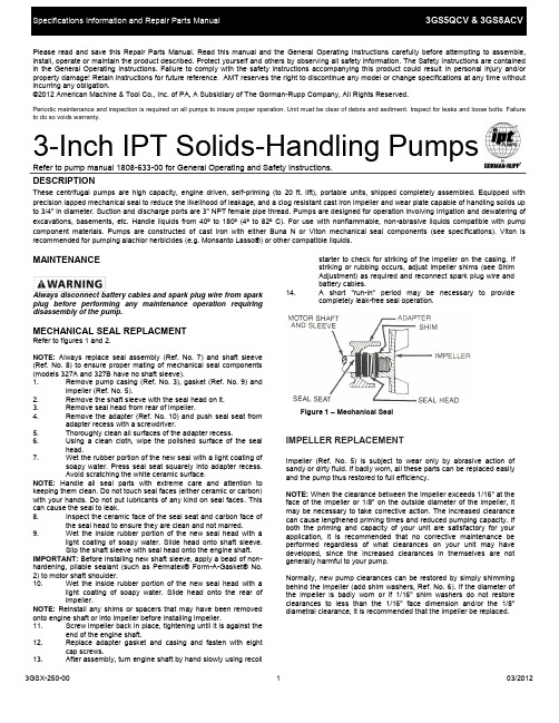
Please read and save this Repair Parts Manual. Read this manual and the General Operating Instructions carefully before attempting to assemble, install, operate or maintain the product described. Protect yourself and others by observing all safety information. The Safety Instructions are contained in the General Operating Instructions. Failure to comply with the safety instructions accompanying this product could result in personal injury and/or property damage! Retain instructions for future reference . AMT reserves the right to discontinue any model or change specifications at any time without incurring any obligation.©2012 American Machine & Tool Co., Inc. of PA, A Subsidiary of The Gorman-Rupp Company, All Rights Reserved.Periodic maintenance and inspection is required on all pumps to insure proper operation. Unit must be clear of debris and sediment. Inspect for leaks and loose bolts. Failure to do so voids warranty.3-Inch IPT Solids-Handling PumpsRefer to pump manual 1808-633-00 for General Operating and Safety Instructions.DESCRIPTIONThese centrifugal pumps are high capacity, engine driven, self-priming (to 20 ft. lift), portable units, shipped completely assembled. Equipped with precision lapped mechanical seal to reduce the likelihood of leakage, and a clog resistant cast iron impeller and wear plate capable of handling solids up to 3/4" in diameter. Suction and discharge ports are 3" NPT female pipe thread. Pumps are designed for operation involving irrigation and dewatering of excavations, basements, etc. Handle liquids from 40º to 180º (4º to 82º C). For use with nonflammable, non-abrasive liquids compatible with pump component materials. Pumps are constructed of cast iron with either Buna N or Viton mechanical seal components (see specifications). Viton isrecommended for pumping alachlor herbicides (e.g. Monsanto Lasso®) or other compatible liquids.MAINTENANCEAlways disconnect battery cables and spark plug wire from spark plug before performing any maintenance operation requiring disassembly of the pump.MECHANICAL SEAL REPLACMENTRefer to figures 1 and 2.NOTE: Always replace seal assembly (Ref. No. 7) and shaft sleeve (Ref. No. 8) to ensure proper mating of mechanical seal components (models 327A and 327B have no shaft sleeve). 1. Remove pump casing (Ref. No. 3), gasket (Ref. No. 9) andimpeller (Ref. No. 5).2. Remove the shaft sleeve with the seal head on it.3. Remove seal head from rear of impeller.4. Remove the adapter (Ref. No. 10) and push seal seat fromadapter recess with a screwdriver.5. Thoroughly clean all surfaces of the adapter recess.6. Using a clean cloth, wipe the polished surface of the sealhead.7. Wet the rubber portion of the new seal with a light coating ofsoapy water. Press seal seat squarely into adapter recess. Avoid scratching the white ceramic surface.NOTE: Handle all seal parts with extreme care and attention to keeping them clean. Do not touch seal faces (either ceramic or carbon) with your hands. Do not put lubricants of any kind on seal faces. This can cause the seal to leak. 8. Inspect the ceramic face of the seal seat and carbon face ofthe seal head to ensure they are clean and not marred.9. Wet the inside rubber portion of the new seal head with alight coating of soapy water. Slide head onto shaft sleeve. Slip the shaft sleeve with seal head onto the engine shaft.IMPORTANT: Before installing new shaft sleeve, apply a bead of non-hardening, pliable sealant (such as Permatex® Form-A-Gasket® No. 2) to motor shaft shoulder. 10. Wet the inside rubber portion of the new seal head with alight coating of soapy water. Slide head onto the rear of impeller.NOTE: Reinstall any shims or spacers that may have been removed onto engine shaft or into impeller before installing impeller. 11. Screw impeller back in place, tightening until it is against theend of the engine shaft.12. Replace adapter gasket and casing and fasten with eightcap screws.13. After assembly, turn engine shaft by hand slowly using recoilstarter to check for striking of the impeller on the casing. If striking or rubbing occurs, adjust impeller shims (see Shim Adjustment) as required and reconnect spark plug wire and battery cables.14. A short "run-in" period may be necessary to provide completely leak-free seal operation.IMPELLER REPLACEMENTImpeller (Ref. No. 5) is subject to wear only by abrasive action of sandy or dirty fluid. If badly worn, all these parts can be replaced easily and the pump thus restored to full efficiency.NOTE: When the clearance between the impeller exceeds 1/16" at the face of the impeller or 1/8" on the outside diameter of the impeller, it may be necessary to take corrective action. The increased clearance can cause lengthened priming times and reduced pumping capacity. If both the priming and capacity of your unit are satisfactory for your application, it is recommended that no corrective maintenance be performed regardless of what clearances on your unit may have developed, since the increased clearances in themselves are not generally harmful to your pump.Normally, new pump clearances can be restored by simply shimming behind the impeller (add shim washers, Ref. No. 6). If the diameter of the impeller is badly worn or if 1/16" shim washers do not restore clearances to less than the 1/16" face dimension and/or the 1/8" diametral clearance, it is recommended that the impeller be replaced.Figure 1 – Mechanical Seal3-Inch IPT Solids-Handling PumpsRepair Parts List1 Suction Plate Kit 3270-050-95 3270-050-95 12 Flapper Valve Kit - Viton 2874-071-90 2874-071-90 13 Casing Kit - Viton 3270-002-95 3270-002-95 1(includes Ref. Nos. 1, 2, 3, & 4) 14 NPT Pipe Plug * * 35 Impeller Kit 327A-010-95 2870-010-95 16 Shim Kit 3827-172-90 1656-000-90 17 ⑤Shaft Seal Assembly - Viton 1641-163-00 1640-163-91 18 Shaft Sleeve N/A 1555-140-03 19 Casing Gasket 1546-000-00 1546-000-00 110 Adapter Kit 327A-030-95 2870-031-95 111 Engine: Honda 1639-042-00 N/A 1Engine: B&S N/A 1639-024-00 112 Frame Mount Kit Incl. w/Ref 13 Incl. w/Ref 13 113 Frame Kit 3120-105-K0 1696-100-K0 1(includes Ref. No. 12)14 Battery Tray Kit (E-Start Models Only) N/A 1696-BAT-K0 1 ❒ 3" NPT Pipe Nipple Kit C367-90 C367-90 1 ❒ Wheel Kit (optional) C402-99 C402-99 1 ❒ 3” NPT Street Elbow1602-000-00 1602-000-00 1 ❒ NPT Suction Strainer (optional) C519-90 C519-90 1 (*) Standard Hardware Item, Available Locally(⑤) Seal assembly available as set only (includes seal head and seat).(❒) Not Shown。
- 1、下载文档前请自行甄别文档内容的完整性,平台不提供额外的编辑、内容补充、找答案等附加服务。
- 2、"仅部分预览"的文档,不可在线预览部分如存在完整性等问题,可反馈申请退款(可完整预览的文档不适用该条件!)。
- 3、如文档侵犯您的权益,请联系客服反馈,我们会尽快为您处理(人工客服工作时间:9:00-18:30)。
Manuale di istruzioni per l’uso e la manuten - Instructions and maintenance manual forZione delSOLLEVATORE ELETTROIDRAULICO ELECTROHYDRAULIC LIFTPER VEICOLI FOR VEHICLES Modello 204I/A Model 204I/AAnno di costruzioneYear of manufactureCOSTRUTTORE: MANUFACTURER:WERTHER INTERNATIONAL S.p.A WERTHER INTERNATIONAL S.p.A Via F. BRUNELLESCHI, 12 Via F. BRUNELLESCHI, 12 42124 CADE’(RE)-ITALY 42124 CADE’(RE)-ITALYTelefono ++/+522/9431 (r.a.) Telefono ++/+522/9431 (r.a.) Telefax ++/+522/941997 Telefax ++/+522/941997WEB WEB E-mail ******************** **************************Rev.1……………………………………29/12/2009CONTENTSPACKING, TRANSPORT AND STORAGE (5)PACKING (5)LIFTING AND HANDLING (5)STORAGE (5)CRATE STACKING (6)OPENING THE CRATES (6)DISPOSAL OF CRATES (6)INTRODUCTION WARNING (6)LIFT SATETY (6)THE SAFETY OF LIFTED VEHICLES (6)CONSERVING THE MANUAL (6)LAWS (7)CHAPTER 1 DESCRIPTION OF THE MACHINE (8)1.1 FIXED STRUCTURE (FIG.4) (9)1.2 MOVING UNITS (SEE FIG.4) (9)1.3 LIFT UNIT (SEE FIG.4) (9)1.4 HYDRAULIC POWER UNIT (FIG.5) (10)1.5 CONTROL BOX (FIG.6) (10)1.6 SAFETY DEVICE (10)CHAPTER 2 TECHNICAL SPECIFICATIONS (11)2.1 ELECTRIC MOTOR (12)2.2 HYDRAULIC UNIT PUMP (12)2.3 OIL (12)2.4 HYDRAULIC OIL DIAGRAM (12)2.5 VEHICLE WEIGHT AND SIZE (14)2.6 MAXIMUM DIMENSIONS OF VEHICLES TO BE LIFTED (15)CHAPTER 3 SAFETY (16)3.1 GENERAL PRECAUTIONS (17)3.2 RISKS OF ELECTRIC SHOCK: (17)3.3 RISKS AND PROTECTION DEVICES (17)3.4 LONGITUDINAL AND LATERAL MOVEMENT (17)3.5 RISKS WHILE THE VEHICLE IS BEING RAISED (18)3.6 RISKS OF PERSONS (19)3.6.1 RISK OF CRUSHING (OPEARATOR) (20)3.6.2 RISK OF CRUSHING (PERSONNEL) (20)3.6.3 RISK OF IMPACT (20)3.6.4 RISK DUE TO VEHICLE MOVEMENT (21)3.6.5 RISK OF VEHICLE FALLING FROM LIFT (21)3.6.6 SLIPPING (22)3.6.8 RISK OF COMPONENT FAILURE DURING OPERATION. (22)3.6.9 RISK RELATED TO IMPROPER USE (23)CHAPTER 4 INSTALLATION (23)4.1 INSTALLATION REQUISITE CHECKLIST (23)4.2 LIGHTENING (24)4.3 FLOOR (25)4.4 ASSEMBLING (26)PUT COLUMN (26)4.4.2 HYDRAULIC PLANT (27)4.4.3 ELECTRIC PLANT CONNECTION (28)4.4.4 ARM ASSEMBLING (29)TESTING AND CHECKS TO PERFORM BEFORE START-UP (30)4.5.1 MECHANIAL TESTS (30)4.5.2 ELECTRIC TESTS (30)4.5.3 OPERATING OF THE FOLLOWING DEVICES (30)4.5.4 HYDRAULIC OIL TEST (31)4.5.5 ROTATION DIRECTION TEST (31)4.6 SET UP (31)4.6.1 VACUUM TEST (without vehicles loaded) (31)4.6.2 LOAD TESTS (31)CHAPTER 5 OPERATIONS AND USE (32)CONMANDS (32)5.1.1 MAIN SWITCH (IG) (32)5.1.2 UP PUSH BUTTON (32)5.1.3 DOWN PUSH BUTTON (32)5.1.4 LOCK PUSH BUTTON (32)5.2 OPERATING SEQUENCE (32)5.2.1 LIFTING (32)5.2.2 PARKING (33)5.2.3 LOWERING (33)CHAPTER 6. MAINTENANCE (33)PRECAUTIONS (33)6.2 PERIODIC MAINTENANCE (34)6.2.1 OPERATION FREQUENCY (34)6.2.2 EVERY MONTH (35)6.2.3 EVERY 3-MONTH... (35)6.2.4 EVERY 6-MONTH... (35)6.2.5 EVERY 12-MONTH... . (36)6.3 PERIODIC LUBRIFICATION CHART (37)CHAPTER 7 TROUBLESHOOTING (38)7.1 TROUBLESHOOTING GUIDE (38)7.2 POSSIBLE PROBLEMS AND SOLUTIONS (38)APPENDIX A-SPECIAL NOTES (39)APPENDIX B SPARE PARTS (39)PACKING, TRANSPORT AND STORAGEALL PACKING, LIFTING, HANDLING, TRANSPORT AND UNPACKING ORERATIONS ARETO BE PERFORMED EXCLUSIVELY BY EXPERT PERSONNEL WITH KNOWLEDGE OF THE LIFT AND THE CONTENTS OF THIS MANULPACKINGThe lift is shipped disassembled into following parts: Weight (kg)Command post; complete with carriage, chain, hydraulic cylinder and control panel 320kg Service side post, complete with carriage, chain and hydraulic cylinder 310kgCrossbeam 30kgLong arms complete with extension and plate 35kgShort arms complete with extension and plate 30kgPower unit complete with motor and support 30kgAccessory package, nuts and bolts 27kgFoot guards 3kgBox containing 4 arm-blocking kitsThe lift is dispatched in an iron crate (Fig.1), weighing approx.850kg.LIFTING AND HANDLINGThe crates may be lifted and moved with a lift truck (Fig.1).If either of the latter two are used , crates must be harnessed with at least 2 slings.Fig.1 Fig.2The equipment chosen must be suitable for safe lifting and moving, bearing in mind the dimensions and weight.STORAGEPacked machinery nut always be kept in a covered, protected place, at a temperature between -10。
And +40。
And must not be exposed to direct sunlight.CRATE STACKINGThe type of packing allows the possibility of stacking up to 3 crates.Up to 3 crates may be stacked one upon the other on lorries or in containers if property positioned and provided they are restrained to prevent falling.OPENING THE CRATESWhen the crates arrive, check that the machine has not been damaged during transport and that all parts listed are present. The crates must be opened using all possible precautionary measure to avoid damaging the machine or its parts. Make sure that parts do not fall from the crate during opening.DISPOSAL OF CRATESThe crates may be reused or recycled.INTRODUCTION WARNINGThis manual has been prepared for workshop personnel expert in the use of the lift (operator) and technicians responsible for routine maintenance (maintenance fitter): read the manual before carrying out any operation with the lift and /or the packing. This manual contains important information regarding:THE PERSONAL SAFETY OF operators and maintenance workers LIFT SATETYTHE SAFETY OF LIFTED VEHICLESExpress the rated load is 4000kg ,don’t allow the lift load weigh excess 4000kg. This symbol express attention should be taken for electrical hazardsCONSERVING THE MANUALThe manual is an integral part of the lift, which it should always accompany even if the unit is sold .The manual must be kept in the vicinity of the lift in an easily accessible place so that the operator and maintenance staff must be able to locate and consult the manual quickly at any time.ATTENTIVE AND REPEATED READING OF CHAPTER 3, WHICH CONTAINS IMPORTANT INFORMATION AND SAFETY WARNINGS, IS PARTICULARLY RECOMMENDED.Lift rack has been designed and built in compliance with the following:LAWSThe lifting, transport, unpacking, assembling, installation, starting up, initial adjustment and testing, EXTRAORDINARY maintenance, repair, overhauls, transport and dismantling of the lift must be performed by specialist personnel from the LICENSED DEALER or an SEVICE CENTRE authorized by the manufacturer (see authorized dealer on frontispiece).The manufacturer declines all responsibility for injury to persons or damage to vehicles or objects when any of the above mentioned operations have been performed by unauthorized personnel or when the rack has been subject to abuse.This manual indicates only the operative and safety aspects that may prove useful to the operator and maintenance works better understanding the structure and operation of the lift and for best use of the lift.In order to understand the terminology used in this manual, the operator must have specific experience in workshop, service, maintenance and repair activities, the ability to interpret correctly the drawings and descriptions contained in the manual and be acquainted with the general and specific safety rules relevant to the country in which the machine has been installed.The same applies to the maintenance fitter, who must also possess specific and specialized knowledge (mechanical, engineering) needed to perform the operations described in the manual in complete safety.The words “operator” and “maintenance fitter” used in this manual are construed as follows:OPERATOR: person authorized to use the lift.WORKING CONDITIONS:1、Regarding ambient temperature shall be 5-40℃.2、Regarding humidity shall be 30-95%.3、Regarding transportation and storage temperature shall bebetween25-55℃,and short period no exceeding 24 hours at up to70℃.4、Regarding installation altitude max 1000m.MAINTENANCE FITTER: person authorized for routine maintenance of the lift.The end user can only use the machine in correct way as defined in instruction.Loose clothes shall not be used protection cap shall also be used for long hair person, etc.The end user should provide the MSDS (Material Safety Data Sheet) at easy accessible place when providing lubrication.CHAPTER 1 DESCRIPTION OF THE MACHINEThe 2-post electro-hydraulic lift is a fixed installation. This means that it is anchored to the ground and built for lifting and positioning automobiles and vans at a certain height off the ground.The lift consists of the following main parts:1. Fixed structure (posts + upper beam);2. Mobile units (carriages + arms);3. Lift units (2 hydraulic cylinders + power unit);4. Control box;5. Safety devices;Figures 3 and 4 illustrate the various parts of the lift and the work areas reserved for use by operators around the lift.Command side: this side of the lift includes the area reserved for the operator to access the control box.Service side: this is the opposite side of the command side.Front side: the side with the short arms.Rear side: the side with the long arms.Fig.31.1 FIXED STRUCTURE (FIG.4)This structure consists of:1. 2 posts, (service 15 and command 3 side post) built with bent steel plate. The base is welded to adrilled plate to be anchored to the floor. The electric control box 4 and the hydraulic power unit 5 are attached to the command post. Inside each post are the moving parts to lift the vehicles. The control panel and the hydraulic unit are fixed to the command post.2. An upper beam 1,17 built with bent steel plate, connecting the upper posts with bolts.Fig.41.2 MOVING UNITS (SEE FIG.4)Each unit consists of:1. Both carriage (10 and 14) built with welded steel plate. It joints by chain 8 and the steel wire 7,and at the bottom to the lift arms by means of pins.The carriage moves along the post, guided by plastic sliding pads, located inside the post itself.2. Two telescopic arms, one long (13) and one short (12), built with tubular steel with a pad at eachend that can be height adjusted to hold the car and on the opposite side the carriage connection hole.1.3 LIFT UNIT (SEE FIG.4)It consists of:1 2 hydraulic cylinders (10), the carriages run by chains, and the cable keep both of them inparallel.1.4 HYDRAULIC POWER UNIT (FIG.5)The hydraulic power unit consists of:1. An electric motor2. A geared hydraulic pump3. Descent hand-valve equipped with a manual oil drain valve (see the use and maintenancechapter)4. A maximum pressure valve5. Oil tank6. An oil delivery and return flexible pipe to the cylinders feeding circuitNote: The oil delivery pipe may be under pressure1.5 CONTROL BOX (FIG.6)The panel that houses the electric control box contains the following:1 Main switch2 Rise push button3 Down push button4 Lock push buttonFig.5 Hydraulic power unit Fig.6 Control panel1.6 SAFETY DEVICEThe safety devices include:1 Mechanical safety device for carriage2 Arms locking system3 4 foot guards on the arms4 A synchronous device to control the carriages movement.5 2 post end limit switches6 General electric safety devices7 General hydraulic safety devicesThese safety devices will be described in further detail in the following chaptersCHAPTER 2 TECHNICAL SPECIFICATIONSCAPACITY……………………………………………4000kg(39200N)Car max lifting height…………………………………1820mmLift min stand height………………………………….100mmClearance between carriages………………………….2760mmTotal width……………………………………………3640mmLong arm maximum len gth………………………….1330mmLong arm minimum length…………………………..845mmShort arm maximum length………………………….1050mmShort arm minimum length…………………………..685mmRise time with three-phase motor……………………≤60secRise time with single-phase motor……………… ….≤75secDescent time…………………………………………18≤t≤40secTotal lift weight………………………………………about 850kgNoise………………………………………………….≤70db (A) 1mOperating temperature……………………………….5℃/40℃Work environment: …………………………… ……closed roomRelative humility……………………………………..90%Sea level height (3500)Fig.7 Dimensions and overall clearances2.1 ELECTRIC MOTORThe motor must be connected with reference to the attached wiring diagrams.The motor rotation wise must be the same as shown by the arrow on the pump: if not, modify the electrical connections (see ch.4.INSTALLATION-electric plant connection)2.2 HYDRAULIC UNIT PUMP2.3 OILThe oil reservoir contains hydraulic mineral oil in accordance with ISO/DIN 6743/4 with a level of contamination that does not exceed class 18/15 according to ISO 4406, for example IP HYDRUS OIL 32; SHELL TELLUS OIL T32 or equivalent.2.4 HYDRAULIC OIL DIAGRAMFig.8 Principle of Hydraulic PartKM SADOWNLOCKKTSBDSBLYA2YA1KTYVYA3YA4UP KTSQ1SBUKM+U124V 160VAT FU16A-FU22APEL3L1 1.5mm20223231I>I>QL2I>SQ2UWV 1112141516172122123456131078DOWNLOCKKTSBDSBLYA2YA1KTYVYA3YA4UP KTSQ1SBUKM+U124V 160VAT FU16A-FU22A20223231SQ2111214151617212213107KM SA UPE NL1.5mmI>Q12N2.5 VEHICLE WEIGHT AND SIZELift rack can be adapted to virtually all vehicles no heavier than 4000kg, the dimensions of which donot exceed the following.2.6 MAXIMUM DIMENSIONS OF VEHICLES TO BE LIFTEDMax width: 2400mmMax wheelbase: 3000mmThe underbody of cars with low ground clearance may interfere with the structure of the lift .Pay particular attention in the case of low body sports cars.Always keep the capacity of the lift in mind in the case of vehicles with particular characteristics. THE SAFETY area will be determined by the dimensions of the vehicle.CHECK OF LARGER VEHICLES. MAXIMUM WEIGHT OF THE VEHICLE TO BE LIFTFig.11 Weight distributionCHAPTER 3 SAFETYIt is vital to read this chapter of the manual carefully and from beginning to end as it contains important information regarding the risks that the operator and the maintenance fitter may be exposed to in the eventuality that the lift is used incorrectly.The following text contains clear explanations regarding certain situations of risk or danger that may arise during the operation or maintenance of the lift, the safety devices installed and the correct use of such systems, residual risks and operative procedures to use (general and specific precautions to eliminate potential hazards).Lift is designed and built to lift vehicles and hold them in the elevated position in a closed workshop. All other uses are unauthorized; in particular, the lift is not suitable for:-Washing and respire work;-Creating raised platforms or lifting personnel;-Use as a makeshift press for crushing purpose;-Use as goods lift-Use as a jack for lifting vehicles or changing wheels.THE MANUFACTURE DISCLAIMS ALL LIABILITY FOR INJURY TO PERSONS OR DAMAGE TO VEHICLES AND OTHER PCABLERTY CAUSED BY THE INCORRECT AND UNAUTHORISED USE OF THE LIFT.During lift and descent movements, the operator must remain in the command station as defined in figure 15. The presence of persons inside the danger zone indicated in the same figure is strictly prohibited. The presence of persons beneath the vehicle during operations is permitted only when the vehicle is parked in the elevated position.DO NOT USE THE LIFT WITHOUT PROTECTION DEVICES OR WITH THE PROTECTION DEVICES INHIBITED. FAILURE TO COMPLY WITH THESE REGULATIONS CAN CAUSE SERIOUS INJURY TO PERSONS, AND IRREPERABLE DAMAGE TO THE LIFT AND THE VEHICLE BEING LIFTED.Fig.12 Working Area3.1 GENERAL PRECAUTIONSThe operator and the maintenance fitter are required to observe the prescriptions of accident prevention legislation in force in the country of installation of the lift.Furthermore, the operator and the maintenance fitter must:1. Always work in the scheduled working area as shown in the manual.2. Never remove deactivate the guards and mechanical, electrical, or other types of safetydevices.3. Read the safety notices affixed to the machine and the safety information in this manual.In the manual all safety notices are shown as follows:DANGER: indicates imminent danger that can result in serious injury or death.WARNING: indicates situations and /or types of maneuvers that are unsafe and can cause injuries of various degrees or death.CAUTION: indicates situations and /or types of maneuvers that are unsafe and can cause minor injury to persons and /or damage the lift, the vehicle or other psaltery.3.2 RISKS OF ELECTRIC SHOCK:Specific safety notice affixed to the lift in areas where the risk of electric shock is particularly high.3.3 RISKS AND PROTECTION DEVICESWe shall now examine the risks to which the operator and the maintenance fitters may be exposed when the vehicle is immobilized in the raised position, together with the protection devices and adopted by the manufacture to reduce all such hazards to the minimum.3.4 LONGITUDINAL AND LATERAL MOVEMENTLongitudinal movement is considered the backward and forward shifting of the load.Lateral movement implies the shifting to the left or right of the vehicle, especially during the lifting phase on the rack.These movements can be avoided by positioning the vehicle correctly on the arm disk support plates, which must be previously adjusted to the same height (by loosening or tightening) as the vehicle.Do not move the vehicle in relation to the arms or adjust arms and disk support plates until the arms have been totally lowered, i.e. the disk support plates must be free from all contact with the vehicle.Fig.13 Risk of vehicle fallWARNINGDO NOT ATTEMPT TO MOVE THE VEHICLE WHEN IT IS RESTING ON THE DISK SUPPORT PLATES.It is important to position the vehicle on the lift so that the weight is correctly distributed on the arms (Fig.14) for person and equipment safety, it is important that:1. People rest inside the safety area while the vehicle raising (Fig.12)2. The engine is off, the clutch engaged and the parking brake pulled.3. The vehicle is correctly positioned. (Fig.14).4. Only authorized vehicle (Fig.10-11) are raised without exceeding the rate capacity and overalldimensions.Fig.14 correctly loaded vehicle3.5 RISKS WHILE THE VEHICLE IS BEING RAISEDThe following safety devices have been installed to protect against overweight conditions and equipment failure:1. The thermal relay in the electric box will trip if the motor is overloaded.2. The maximum pressure valve (fig.15), located on the hydraulic oil power unit, will trip if the liftis overloaded.3. In case of a sudden, great leakage in the hydraulic circuit (a broken pipe), the blocking valves,at the bottom of each cylinder, will trip (fig.16).4. If the lift reaches to the maximum height, push the button to stop it(Fig.17).5. Keep both cables in balance during raising or lowering (Fig.18).6. If the hydraulic cylinder breaks, the safety wedges will trip (fig.19), located inside the posts.The wedges are pushed by the spring and immediately stop the carriage preventing their descent.Fig.15 Fig.16Fig.17 Fig.18Fig.197. If the moving part exceed its travel distance, on the upper part of the command post there istwo limit switches connected in series and are usually set working by the “actuator”(fig.17) on the command side carriage. If the first limit switch did not work, the second one would trip after 3sec of carriage run.8. In case of total breakdown of the limit swatches, the carriage will stop a few mm higher,because the hydraulic cylinders come to end stroke, will cause the maximum pressure valve (on hydraulic unit) to trip.3.6 RISKS OF PERSONSThis paragraph illustrates risks to which the operator, maintenance worker, or any person near the operating area of the lift may be exposed in the case of impeccable use of equipment.3.6.1 RISK OF CRUSHING (OPEARATOR)Possible if the operator controlling the lift is not in thespecified position at the command panel. When theplatform and the vehicle are descending, theoperator must never be partly or completelyunderneath the moving structure. During this phasethe operator must remain in the command zone(Fig.20).Fig.203.6.2 RISK OF CRUSHING (PERSONNEL)When the platform and the vehicle are descendingpersonnel are prohibited from entering the areabeneath the moving parts of the lift. (Fig.21) .the liftoperator must not start the maneuver until it hasbeen clearly established that there are no persons inpotentially dangerous positions.Fig.213.6.3 RISK OF IMPACTCaused by the parts of the lift or the vehicle thoseare positioned at head height. When, due tooperational reasons, the lift is immobilized atrelatively low elevations (less than 1.75m from theground) personnel must be careful to avoid impactwith parts of the machine not marked with specialhazard coloring (Fig.22).Fig.223.6.4 RISK DUE TO VEHICLE MOVEMENTMovement may be caused during operations, whichinvolve force sufficient to move the vehicle (fig.23). Ifthe vehicle is of considerable dimensions or weight.Movement may lead to overload or unbalancing; allmeasures must be taking to avoid such anoccurrence.3.6.5 RISK OF VEHICLE FALLING FROM LIFTThis risk could be caused by the incorrectpositioning on the arm disk support plates (Fig.24) orin incorrect position of the arm disk support plates inrelation to the lift.Fig.24NEVER BOARD THE VEHICLE AND/OR TURNTHE ENGINE ON WHEN LIFT IS RAISED (FIG.25) Fig.25NEVER LEAN OBJECTS AGAINST THE POSTSOR LEAVE THEM IN THE AREA WHERE MOVINGPARTS ARE LOWERED.This could hamper lowering or cause the vehicle tofall from the rack (Fig.26)3.6.6 SLIPPINGThis risk may arise due to spillage of lubricants inthe surrounding area (fig.27).ALWAYS KEEP THE AREA SURROUNDING THELIFT CLEAN BY REMOVING ALL OIL SPILLS.To avoid the risk of slipping, make use of therecommended personal protection (anti-slipfootwear).Fig.273.6.7 RISK OF ELECTRIC SHOCKRisk of electric shock in areas of the lift housingelectric wiring. Do not use jets of water, steam (highpressure wash units), and solvents Or paint in theimmediate vicinity of the lift, and take special care tokeep such substances clear off the electricalcommand panel (fig.28).Fig.283.6.8 RISK OF COMPONENT FAILURE DURINGOPERATION.The manufacturer has used appropriate materialsand construction techniques in relation to thespecified use of the machine in order to manufacturea reliable and safe lift. Note however, that the liftmust be used in conformity with the manufacturersprescriptions and the frequency of inspections andmaintenance work recommended in chapter 6“MAINTENANCE” must be observed.Fig.293.6.9 RISK RELATED TO IMPROPER USEPersons are not permitted to stand or sit on theplatforms during the lift maneuver or when thevehicle is already lifted(fig.29). All uses of the liftother than the uses for which it was designed areliable to give rise to serious accidents involving thepersons working in the immediate vicinity of the unit.It is therefore essential to adhere scrupulously to allregulations regarding use, maintenance and safetycontained in this manual.3.7 SAFETY INSTRUCTINS FOR SERVICING1. Maintenance or repair work by authorized service personnel only.2. Turn off and padlock the main switch before doing any maintenance,or repair work.3. Work on pulse generators or proximity switches by authorized service personnel only.4. Work on the electrical equipment by certified electricians only.5. Do not replace or override the safety devices.6. Ensure that ecologically harmful substances are disposed of only in accordance with theappropriate regulations.CHAPTER 4 INSTALLATIONTHE FOLLOWING OPERATIONS MUST BE PERFORMED EXCLUSIVELY BY SPECIALISED TECHNICAL STAFF WITH AUTHORISATION FROM THE MANUFACTURER OR LICENSED DEALER. IF THESE OPREATIONS ARE PERFORMED BY OTHER PERSONS, SERIOUS PERSONAL INJURY AND/OR IRREPERABL DAMAGE TO THE LIFT UNIT MAY RESULT.4.1 INSTALLATION REQUISITE CHECKLISTThe lift is designed for installation in enclosed areas suitably protected from the weather. The place of installation must be well clear of areas destined to washing or painting, and away from solvent or paint storage areas or areas where there is a risk of potentially explosive atmosphere.SUITABILITY OF THE DIMENSIONS OF THE PLACE OF INSTALLATION AND SAFTY CLEARANCE.The lift must be installed in observance of the clearances between walls, pillars, other machines, etc. indicated in figure 30 and incompliance with any legislative requirements in the county of installation.Check in particular:1. Minimum height: 5000mm inclusive of height of vehicle, maximum height of arms,( i.e. 1900mm),and upper post height (i.e.2828mm)2. minimum distance from walls: 600mm3. Minimum working area: 700mm4. Area for command station5. Area for maintenance, access and emergency escape routes.6. Position in relation to other machines7. Proximity to power supply for trouble-free hook-upFig. 304.2 LIGHTENINGAll parts of the machine must be uniformly lit with sufficient light to assure that the adjustment and maintenance operations specified in the manual can be performed, and without areas of shadow reflected light, glare and avoiding all situations that could give rise to eye fatigue.The lighting must be installed in accordance with the laws in force in the place of installation (responsibility lies with the lighting equipment fitter)4.3 FLOORThe lift must be installed on a horizontal concrete bed with a minimum thickness of 200mm built and a resistance ≥30N/mm2.The floor must also be flat and level (10mm of tolerance for leveling). Consult the manufacturer with regard to special applications.Fig.324.4 ASSEMBLINGWARNINGDURING INSTALLATION ONLY AUTHORISED PERSONNEL IS ALLOWEDTo assemble the lift, the weight of the various parts is to be considered, in order to provide a lifting machine with the minimum capacity 500kgMax. Lifting height 2900mmBefore starting to assemble the lift, check the crate contains all the needed material.PUT COLUMN1. Position the base plate of both column of which the open side should be inner side oriented.Make sure the distance from up to bottom should be 2760mm. The thickness of the spacer is over 300mm to ensure the operation of installing safety devices, cables, oil pipe and wire.2. Install safety devices, which including solenoid, self-locking board and hook according to fig.33.Fig.333. Connect crossbeams to both columns to both columns to fig.34.(Notice that the limited switchedFig.344. Install the safety bar according to fig.35 and fig.36.Fig.35 Fig.36Fig.37 Fig.386. Connect the long hose inside both columns according to fig.40, tighten (upside connect to maincolumn and the down side connect with sub-column), and then fix the oil pipe by using clip. 7. Install the electrical box on the main column and then cross all the wires through holes andconnect with limited switch and solenoid.8. Put up the main column (Notice that the carriage engages in the ratchet and keep in the sameheight). Adjust the uprightness of the column and install the expansion bolt according to fig.32.9. Adjust two balance cables.4.4.2 HYDRAULIC PLANT1. Connect the pump on the connecting board according to fig.41 and then fix on the main column.2. Connect the hydraulic unit to the circuit crossing with a flexible pipe(Fig.40).3. Tight all the fittings very well, even the one already mounted by the manufacturer.4. Full the hydraulic unit tank with 8 liters of hydraulic oil ISO 32 as IP HYDRUS OIL 32, SHELLTELLUS OIL T32 or similar (See Ch.2, Technical specifications).5. Remove the oil filling cap and substitute it with the given drain cap.Fig.39。