博世力士乐系列手册
bosch rexroth 4 3-4 2 直流电磁阀 手册说明书

4/3 - 4/2 Directional valves L50A0… (LC04-A)Replaces: 07.12 solenoid operatedRE 18305-11Edition: 06.2022▶Size 4▶Series 00▶Maximum operating pressure 310 bar (4500 psi)▶Maximum fl ow 25 l/min (6.6 gpm)ContentsOrdering details 2Functional description 4Technical data 5Characteristic curves 7External dimensions and fi ttings 8Electric connection 9 L50A0… (LC04-A)General specifi cations▶Direct solenoid operated spool valve, standard version.▶Spool switching is by on off solenoids with a centraltube and removable coil.▶Spring centered control spool.▶For mounting on industry standard surfaceport pattern to CETOP RP121 H-4.2-P02.▶Wet pin DC solenoids with removable coil and manualoverride.▶Manual override as option (push or screw-in type).▶Coil can be rotated through 360°.▶Available electrical connections: DIN 43650 – ISO 4400,AMP JUNIOR, DT04-2P (Deutsch), Free leads.RE 18305-11/06.2022,2L50A0… (LC04-A) | 4/3 - 4/2 Directional valves Ordering detailsOrdering details0102030405060708 L50A0Family01Directional Valves L Type02CETOP Valves5 Size03NG 4 (P02)0 Operation04Solenoid operated D36 coil A0 Spool variants054/3 operated A and B side_ 2 _ _ 4/2 operated A and B side_ 2 _ _ 4/2 operated A side_ 3 _ _ 4/2 operated B side_ 4 _ _ 4/2 operated A and B side with detent_ 5 _ _ Voltage supply31070403010006Without coil–––––●0012 V DC●●●●●–OB24 V DC●●●●●–OC48 V DC–●●●●–OD96 V DC––––●–OU205 V DC––––●–AH Electric connections07Without coils00 With coils, without mating connector011) DIN EN 175301-803With coils, with bi-directional diode, without mating03 connector vertical Amp-JuniorWith coils, with bi-directional diode, without mating04 connector horizontal Amp-JuniorWith coils, with bi-directional diode, without mating07 connector DT04-2PWith coils and bipolar sheathed lead31 300mm (11,8 in) longOptions08Standard00 External push button manual override EPScrew-in type manual override EF●=Available–=Not available1) For connectors ordering code see data sheet RE 18325-90., RE 18305-11/06.2022RE 18305-11/06.2022, 4/3 - 4/2 Directional valves | L50A0… (LC04-A)Ordering details3Spool variants=A201=C201=E201AB_ 2 _ _P T ababAB_ 2 _ _P T ababAB_ 3 _ _P T aaAB_ 4 _ _P T 0bbAB_ 5 _ _P Tabab=G209=K209=L201=N201=L501=N501=A301=B301=C301=D301=E301=K301=T301=Y301=A401=B401=C401=D401=E401=K401=T409=Y401=B201=D201=G201=K201=M201=M501=A361=B361=C361=D361=E361=N301=X301=A471=B471=C471=D471=E471=N401=X4014L50A0… (LC04-A) | 4/3 - 4/2 Directional valves Functional descriptionFunctional descriptionType L50A0The solenoid operated valves type L 50A0 provide 3-way or 4-way fl ow control, usually from port P to either port A or B, and the consequent fl ow return to T from B or A respectively.The valves are composed by a central cast iron body (1) which mounts on industry standard surfaces where thefl ow ports and the installation holes are located; the central body houses the precisely machined directional control spool (2) which is held in the neutral or initial position by the return springs (4). One or two solenoids, composed by a central tube and a surrounding coil (5), are fi tted to the body at the spool’s ends: when the coils are energized, their magnetic fi eld develops a force on the oil immersed mobile plunger incorporated in the tube which pushes the control spool from the initial position into a shifted position where oil fl ow is allowed from P to either A or B.With coils (5) de-energized, the control spool (2) returns to the central or initial position pushed by the washers (3) supported by the return springs (4).The coils (5) are locked on the tube by threaded plastic nuts (6); the tube incorporates an externally reachable push rod (7) which can pushed for emergency spool shifting in case of electric failure.Type L50A0L201_, L50A0M201_, L50A0N201_These valves do not have return springs (4) for the directional control spool (2): the spool can shift between two positions, driven only by the magnetic force developed by the two solenoids (5), and, when the solenoids are not energized, the neutral position of the spool is not defi ned. The directional control spool holds a specifi c position only when one of the solenoids is maintained energized.Type L50A0L501_, L50A0M501_, L50A0N501_In these valves the directional control spool has two switched positions, each one with a mechanical detent. Shifting of the spool’s position is achieved by energizing one of the solenoids, but it is unnecessary to maintain the coil energized in order to keep the spool shifted., RE 18305-11/06.20224/3 - 4/2 Directional valves| L50A0… (LC04-A)5Technical dataTechnical dataVoltage tolerance (nominal voltage)%-10 .... +10Duty Continuous, with ambient temperature ≤ 50°C (122°F)Coil wire temperature not to be exceeded°C (°F)180 (356)Insulation class HCompliance with Low Voltage Directive LVD 73/23/EC (2006/95/EC), 2004/108/EC Coil weight with connection EN 175301-803kg (lbs)0.18 (0.40)Voltage V12244896205 Voltage type DC DC DC DC DC Power consumption W2020202020 Current (nominal at 20 °C (68 °F))A 1.620.840.450.210.01 Resistance (nominal at 20 °C (68 °F))Ω7.428.4106.44512062NoteFor applications with diff erent specifi cations consult us.RE 18305-11/06.2022,6L50A0… (LC04-A) | 4/3 - 4/2 Directional valves Technical data(Ex. DIN 43650)NoteFor further versions (i.e. cable single lead) contact factory., RE 18305-11/06.2022RE 18305-11/06.2022, 4/3 - 4/2 Directional valves | L50A0… (LC04-A) Characteristic curves7Characteristic curvesMeasured with hydraulic fl uid ISO-VG32 at 45° ±5 °C (113° ±9 °F); ambient temperature 20 °C (68 °F).Performance limits5 1 4 3 2bar350300250200150100500 5 10 15 20 25l/min 0 1 2 3 4 5 6 6.6 gpmpsi 50004000300020001000P r e s s u r e pFlow QB201; B301; B401; B361; B471; C201; C301; C401; C361; C471; L201; L501; M201; M5012E201, E301, E401; E361; E471; D201, D301, D401; D361; D471; K201, K209; K301; K401; T301; T4093X301; X401; Y301; Y4014N201; N301; N401; N5015The performance curves here shown are applicable when oil fl ow is travelling in both directions, example P>A and B>T. In special circuit schemes the performance limits can be lower.G201, G209B201, B301, B401 5577B361, B4715588C201, C301, C401, C361, C471, D201, D301, D401; D361, D47166688E201, E301, E401, E361, E471, K201, K209, K301, K4015588L2015587L5013577M2013376M5012365N20133N30125N40152N50123T301, T40955X301, Y3013586X401, Y4015368P r e s s u r e Δp1 2 3 4 5 6 7 80 5 10 15 20 25 l/min bar 2016128400 1 2 3 4 5 6 6.6 gpmpsi 290250200150100500Flow Q8L50A0… (LC04-A) | 4/3 - 4/2 Directional valvesExternal dimensions and fi ttingsDimensions [mm (inches)] External dimensions and fittings1 Solenoid tube O 16mm (0.63inch).2 Blinding plug for 2 positions version.3 Ring nut for coil locking O 26,5 mm (1,04inch).Torque 3 – 4 Nm (2.2 – 3.0 ft-lb).4 Drilling specifi cations of standard mounting surface according toCETOP RP 121 H-4.2 4-P02.5 Locking screws 3 pieces: UNI 5931 (ISO 4762) hexagon sockethead cap screw M 5x25, recommended specifi c strength 8.8class. Torque 5 ÷ 6 Nm (3.7÷4.4 ft-lbs).6 Gap needed for connector removal.7 Optional push-button type manual override for spool opening:it is pressure stuck to the ring nut for coil locking.Mat no. R930059524.8 Optional screw type manual override for spool opening: it isscrewed torque 6-7Nm (4.4-5.2 ft-lb) to the tube as replacement of the coil ring nut. Mat no. R930059561.9 Identifi cation label., RE 18305-11/06.2022RE 18305-11/06.2022, 4/3 - 4/2 Directional valves | L50A0… (LC04-A)Electric connection9Dimensions [mm (inches)]E lectric connection 0001()()()()()()03Protection class: IP 65 with female connectorproperly fi tted (see drawing).04Protection class: IP 65 with female connectorproperly fi tted (see drawing).()()()()()()()()()()()()()3107Protection class: IP 69 K with female connector properly fi tted (see drawing).()()()()()()()()()()()()()()10, RE 18305-11/06.2022Bosch Rexroth Oil Control S.p.A.Oleodinamica LC Division Via Artigianale Sedrio, 1242030 Vezzano sul Crostolo Reggio Emilia - Italy Tel. +39 0522 601 801Fax +39 0522 606 226 / 601 802***************************************/compacthydraulics© This document, as well as the data, specifi cations and other information set forth in it, are the exclusive property of Bosch Rexroth Oil Control S.p.a.. It may not be reproduced or given to third parties without its consent.The data specifi ed above only serve to describe the product. No statements concerning a certain condition or suitability for a certain application can be derived from our information. The information given does not release the user from the obligation of own judgment and verifi cation. It must beremembered that our products are subject to a natural process of wear and aging.Subject to change.。
博世力士乐MSK电机手册

同步伺服电机IndraDyn SMSK 适用于所有要求2Bosch Rexroth AG | Electric Drives and Controls同步伺服电机IndraDyn S n MSK 适用于所有要求• 项目规划手册• 适用于爆炸危险场合的应用描述紧凑和高效• 最大扭矩可达 495 Nm • 最大转速可达 9,000 rpm • 用于不同应用的编码器系统• 高防护等级 IP65• 不同的冷却方式MSK 电机的显著特点就是功率范围较宽,尺寸大小分级很细。
该同步伺服电机的高扭矩密度可实现具有高达 495 Nm 最大扭矩的紧凑设计。
我们可根据需要达到的准确性为您提供满足标准要求或精确性要求的带编码器系统的电机。
您既可以在单圈也可以在多圈结构中选择使用两种不同编码器系统。
轴键槽、保持制动器、较低的侧隙和高防护等级 IP 65 等许多其他选配件意味着其可搭配风扇、液体冷却和 ATEX 使用。
如需在更高的持续功率下应用,则可选用轴向或径向安装的可选配风扇单元来进行改造。
内部安全 IP65 风扇电机(UL 热保护等级 F)确保单相风扇单元的可靠性,无需外部断路器。
借助于可选配的液冷系统,可达到您需要的最大功率。
技术数据Electric Drives and Controls | Bosch Rexroth AG3同步伺服电机IndraDyn S n MSK 适用于所有要求4Bosch Rexroth AG | Electric Drives and Controls 同步伺服电机IndraDyn S n MSK 适用于所有要求上述所有规格数据均基于配有编码器 S1 和无保持制动器的基本型电机750 V 直流母线电压时的数值尺寸Electric Drives and Controls | Bosch Rexroth AG5同步伺服电机IndraDyn S n MSK 适用于所有要求6Bosch Rexroth AG | Electric Drives and Controls 同步伺服电机IndraDyn S n MSK 适用于所有要求Electric Drives and Controls | Bosch Rexroth AG7同步伺服电机IndraDyn S n MSK 适用于所有要求上述所有规格数据均基于配有编码器 S1 和无保持制动器的基本型电机Local contact information can be found at:/adressenBosch Rexroth AG Postfach 13 5797803 Lohr, Germany Bgm.-Dr.-Nebel-Str. 297816 Lohr, Germany Tel. +49 9352 18-0Fax +49 9352 18-8400/electrics© Bosch Rexroth AG 2012 Subject to modification.Printed in GermanyThe data specified above only serve to describe the product. As our products are constantly being further developed, nostatements concerning a certain condition or suitability for a certain application can be derived from our information. The information given does not release the user from the obligation of own judgment and verification.It must be remembered that our products are subject to a natural process of wear and aging.。
博世力士乐系列手册
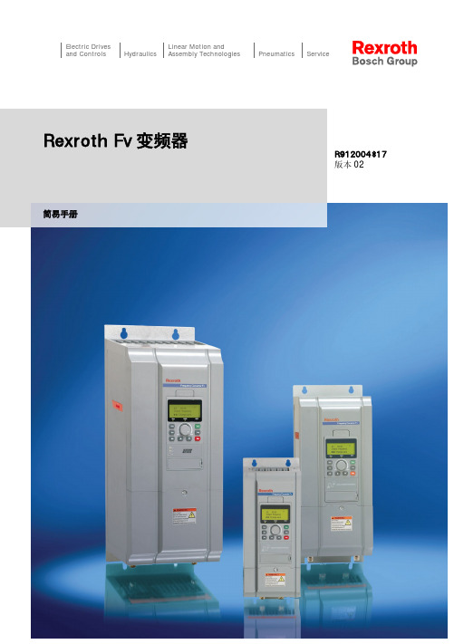
Electric Drivesand Controls Hydraulics Linear Motion andAssembly Technologies Pneumatics ServiceRexroth Fv变频器R912004817版本02简易手册Bosch Rexroth AG更改过程出版颁发日期备注DOK-RCON02-FV*********-IN01-ZH-P2013年6月第一版DOK-RCON02-FV*********-IN02-ZH-P2014年2月增加了新功能关于此文档该《简易手册》基于产品《使用手册》,《使用手册》包含产品的详细数据。
在未通读产品《使用手册》中的安全相关章节内容以及产品标准供货所附《安全说明》前,请勿操作该产品。
参考文档如需其他类型或语言的文档,请联系当地代理商或访问以下网址/fv版权© 博世力士乐(西安)电子传动与控制有限公司 2014该文档以及其中的数据、技术规格和其它信息均为博世力士乐(西安)电子传动与控制有限公司的专有财产。
未经同意,禁止复制或供第三方使用。
责任规格数据仅用于产品说明,如果未在合同中明确规定,不得视为对特性的保证。
本公司保留关于该文档内容和产品可用性的所有权利。
RS-e33bb6b630945a4d0a6846a5018ae8cb-2-zh-CN-6Bosch Rexroth AG目录目录页数1 结构安装 (1)1.1 目视检查 (1)1.2 环境条件 (1)1.3 安装条件 (2)1.4 外型尺寸 (3)2 电气安装 (7)2.1 电缆规格 (7)2.2 主回路端子 (12)2.3 控制信号端口的连接 (13)3 设置参数 (18)3.1 操作面板 (18)3.2 起动 (18)3.3 操作指导 (20)3.4 参数列表 (21)4 故障指示 (41)DOK-RCON02-FV*********-IN02-ZH-P IBosch Rexroth AGII DOK-RCON02-FV*********-IN02-ZH-P1 结构安装1.1 目视检查打开变频器包装后,请进行目视检查。
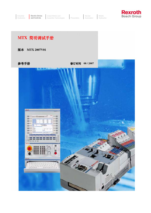
RexrothMTX简明调试手册
2.2.4 键盘------------------------------------------------------------------------------13 2.2.5 RECO Inline 模块-------------------------------------------------------------14 2.2.6 驱动器---------------------------------------------------------------------------17
修订时间 08 / 2007
前言
首先,欢迎您使用博世力士乐的产品,本手册主要面向机床及相似应用的 OEM 厂商所编制,里面主要介绍了 MTX 在应用方案中的常用配置、接线方式及一个简 单的工程实例,希望对您的设计有所帮助。如果您在设计初期,对安装尺寸有所 需求,可以直接参阅我们在附录中的硬件尺寸介绍。
2.2.2 工控机---------------------------------------------------------------------------7
2.2.3 操作面板------------------------------------------------------------------------10
3. PLC 主程序的编制-----------------------------------------------------------------------------40
5) 编译、下载及运行 PLC 程序--------------------------------------------------------40
六、螺距补偿----------------------------------------------------------------------------------------------56 七、数据的备份与恢复----------------------------------------------------------------------------------58
CVF G3变频器说明书
前 言感谢您选用博世力士乐电子传动与控制(深圳)有限公司的变频调速器(以下简称变频器)!CVF - G3系列、CVF - P3系列变频器是自主开发、生产的高性能变频器,该产品采用高品质的元器件、优质材料,并融合高新微电脑控制技术制造而成。
本使用手册提供如下产品系列的操作指南:(1) CVF-G3系列通用型变频器(2) CVF-P3系列风机、水泵专用型变频器本手册阐述了用户安装配线、参数设定、故障诊断和故障排除、日常维护等相关事宜。
为确保能正确操作此系列变频器,发挥其优越性能,请在装机之前,详细阅读本使用手册,并请妥善保存,或将本手册交于该机器的使用者。
如对于本变频器的使用存在疑问或有特殊要求,请随时联络本公司的各地办事处或经销商,也可与本公司总部售后服务中心联系,我们将竭诚为您服务。
我们一直致力于产品的不断完善,故本系列变频器的相应资料(操作手册、宣传资料等)如有变动,恕不另行通知。
欢迎选用本公司其它系列变频器产品:CVF-ZS系列注塑机专用型变频器CVF-ZC系列注塑一体化柜机CVF-LS1系列拉丝机专用型变频器CVF-LY1系列络筒机/印花机专用型变频器CVF-S1 系列单相小功率变频器CVF-SMP系列简易型单相小-1-功率变频器CVF-MN1 系列迷你型单相小功率变频器CVF-V1 系列高性能矢量型变频器开箱时,请认真确认以下内容:1.产品是否有破损,零部件是否有损坏、脱落现象,主体是否有碰伤现象;2.本机铭牌所标注的额定值是否与您的订货要求一致;3.本公司在产品的制造及包装出厂方面,质量保证体系严格,但若发现有某种检验遗漏,请速与本公司或供应商联系,我们将在第一时间为您解决。
变频器型号说明:-2-目录1.注意事项...................................................11.1 安全标识定义..........................................11.2 安装注意事项..........................................11.3 使用注意事项..........................................21.4 报废注意事项..........................................42.安装与配线..............................................52.1 产品技术指标及规格.................................52.2 系列型号说明.....................................72.3 安装环境要求.................................82.4 变频器的安装尺寸...................................82.5 操作面板尺寸...................................102.6 盖板的拆卸与安装....................................112.7 操作面板的拆卸与安装................................112.8 安装方向与空间......................................122.9 变频器的配线........................................132.10 回路端子台的配线....................................212.11 JP跳线说明.........................................282.12 接线说明............................................293.操作与运行 .............................................353.1 面板操作............................................353.2 名词术语说明.......................................363.3 面板功能说明....................................393.4 键盘操作方法.....................................403.5 变频器的运行.....................................444.功能参数一览表 .........................................474.1 基本运行参数(b参数)................................474.2 中级运行参数(L参数).................................48- 3 -4.3 高级运行参数(H参数).................................514.4 状态监控参数一览表...................................554.5 保护功能及对策......................................574.6 故障记录查询........................................585.功能详细说明 ............................................605.1 基本运行参数(b参数)..................................605.2 中级运行参数(L参数).................................685.3 高级运行参数(H参数).................................836.维护与保养 ............................................976.1 日常检查与保养.......................................976.2 定期维护.............................................986.3 易损部件的检查与更换.................................996.4 存放及保修............................................99 7.使用范例.................................................1017.1 面板控制起、停, 面板电位器设置频率.....................1017.2 三线制控制模式........................................1027.3 外部控制方式、外部电压设定频率.........................1037.4 多段速运行、外部控制方式...............................1047.5 可编程多段速控制......................................1057.6 多台变频器的联动运行(群组控制) .......................1067.7 用变频器构成闭环控制系统..............................1107.8 用上位机(PC)控制多台变频器...........................111 8.选件.....................................................1138.1 远控线缆和远控适配器................................1138.2 供水附件............................................1138.3 制动组件............................................113- 4 -附录1:RS485通讯协议........................................115附录2:供水附件的应用.......................................126- 5 -- 6 -第一章 博世力士乐电子传动与控制(深圳)有限公司 注意事项为了确保您的人身、设备及财产安全,在使用变频器之前,请务必仔细阅读本章内容,并在以后的搬运、安装、运行、调试与检修过程中遵照执行。
Convo 变频器选型手册说明书

Convo变频器选型手册u FSCS01u FSCG05u FSCP05博世力士乐 (西安) 电子传动与控制有限公司2产品采用高性能功率模块,确保设备运行稳定可靠;高速微电脑芯片配以高效的专业控制软件,保证设备始终运行在最佳状态;壳体和配件由数控设备自动完成加工,美观坚固;引入ISO9001质量体系,最大化消除质量隐患,承诺提供给客户最优的产品。
Convo 在解决变频器各种应用问题方面是您强大的合作伙伴。
我公司高能效的变频器产品可以提供精准的程序及速度调控,为您实现可观的能源减耗。
作为博世力士乐品牌家族的成员,我们始终致力于为我们的客户呈递高品质的变频器产品。
3公司介绍博世力士乐 (西安) 电子传动与控制有限公司致力于在中国工控传动领域发展,这也是博世力士乐未来在中国工控传动领域成功的重要保证。
博世力士乐 (西安) 电子传动与控制有限公司是德国博世集团的全资子公司。
力士乐是独一无二的,因为在世界市场上,没有其他的品牌能向顾客提供所有的传动与控制技术。
专业化与一体化并举,正因如此,我们在驱动、控制及运动控制技术等领域成为了世界性的榜样。
所有这一切既给予我们鼓舞,也赋予我们责任。
博世力士乐,The Drive & Control Company,独一无二。
4节能目前Convo系列变频器在中国区域内应用于众多行业,如纺织、印染、冶金、电力、石油、化工、建筑楼宇、市政、建材、机床等,其应用节能率在风机、水泵行业尤其突出,另外在球磨机、空压机、注塑机、压铸机等专用设备上也非常明显,节能率最高可达到60 %。
5系列产品技术指标Convo6FSCS01 (CVF-S1)系列变频器精巧、实惠、灵活、可靠多功能单相变频器单相220 V 0.4...2.2 kW产品特点精巧n专注单相小功率n紧凑设计,节省安装空间实惠n高性价比,内置PID控制,内置制动单元n高利用率,面板可拆卸,多机切换使用灵活n16段速运行,特有摆频功能n5路可编程数字输入,3路专属数字输入n支持脉冲输入 (0...10 kHz) ,自带调速电位器n可通过面板延长轻松实现远程控制可靠n卓越品质来自博世标准生产系统n保护完善 (缺相、短路、过流、过压、欠压、过载、过热等)n电路板增强涂层,防尘防腐蚀行业应用机床行业u研磨机u磨床u线切割机纺织印染u纺纱机u整定机u染布机塑料行业u网套机暖通空调u风机u水泵u压缩机u玻璃研磨机械玻璃行业u玻璃研磨机械其他设备u陶瓷送粉机u传送带u医疗离心机u游戏机7丰富的市场经验,可靠的品质保证FSCS01系列均通过博世标准生产系统,蕴含多年的市场品质保证。
力士乐变频器选型手册说明书
力士乐变频器选型手册2目录公司介绍 3我们的目标 4产品简介 5EFC 3600变频器 6Fe变频器 10Fb变频器 14Fv变频器 18附件选配参考 23服务及支持 313公司介绍博世力士乐(西安)电子传动与控制有限公司是德国博世集团的全资子公司,致力于在中国工控传动领域的发展,以变频器作为主营业务,以在德国和中国共同建立的实力强大的研发团队作为基础,同时凭借先进的技术、科学的管理以及优秀的员工队伍,屡创佳绩。
力士乐全系列变频器,凝聚中德技术精髓,满足不同细分市场的客户需求,能最大限度满足各种应用场合,使客户成功地逾越技术隔阂,获得最佳解决方案。
作为国内外众多优秀机械和系统制造商的合作伙伴,提供卓越的全方位的售后服务和技术支持也进一步巩固了博世力士乐在全球范围的领先地位。
这一切既给予我们鼓舞,也赋予我们责任。
博世力士乐,The Drive & Control Company,独一无二。
4我们的目标:成为全球市场的领导型企业,积极服务于客户的利益凭借着广泛的产品与服务系列,我们能够快速、灵活地响应用户的各种要求从产品开发和生产,直至销售和技术服务。
我们时刻与用户紧密合作,力求实现每一项应用系统的最佳解决方案。
正是通过我们的产品和专业技术人员,我们让用户获得决定性的竞争优势,同时确保最小的技术投入和经济负担。
纵观全球市场,作为电子传动与控制整体解决方案的专业服务提供商,在保持技术领先的同时,我们还不断迎接各种新的挑战;在世界80多个国家,公司拥有大约35,000名员工。
这一切,都要归功于公司在规划基础架构时,始终牢记贴近合作伙伴和客户实际需要的经营宗旨。
博世力士乐有着200多年的悠久历史和传统。
作为Robert Bosch GmbH 的一家全资子公司,我们已成为活跃于世界各地的这家力士乐为用户提供传动、控制与运动技术领域所需要的全套产品和服务: f 电子传动与控制 f 工业液压 f 行走机械液压 f 线性技术 f 组装技术 f 气动技术技术集团的一部分。
力士乐VLC系列小型PLC 选型手册说明书
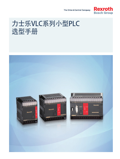
力士乐VLC系列小型PLC 选型手册2产品简介VLC 2000系列小型PLC是博世力士乐为中国市场量身定制的一款工业自动化控制类产品,本产品以丰富的功能、卓越的性能、灵活的扩展性以及优异的品质,给用户提供优秀的控制解决方案。
VLC 2000系列PLC产品最大可以扩展32个模块,具备最大512点数字量、128路模拟量通道的控制能力,可同时处理最多32个PID运算,最多能够扩展到5个通讯口,基于强大的逻辑控制和数据处理能力,并且具有丰富的运动控制能力,可以广泛的应用于印刷包装、纺织、电子产品制造、机床、暖通空调、建筑智能化等多个行业。
VFC 5610HMI执行器3技术参数4丰富的通讯► 标配RS232通讯口,作为编程口使用,同时也可直接连接HMI 。
►通过选件卡可以扩展RS232/RS485/CANopen 接口。
► 支持标准的Modbus RTU/ASCII 协议,同时也支持客户自定义自由通讯协议。
强大的功能► 灵活易用的通讯应用,可以通过表格配置方式代替冗长的通讯及效验指令。
► 强大的高速计数性能,单机最多8路高速计数,支持单相计数模式、计数 加方向模式、AB 相计数模式。
► 丰富的中断控制,最多支持16路外部中断,8种定时中断。
► 单机最多36点的输入脉冲捕捉功能。
► 丰富强大的计时器功能,支持0.01 s ,0.1 s 及1 s 的普通定时器,同时具 有0.1 mS 的高速定时功能。
► 高速脉宽调制输出,支持最多4通道的高精度脉宽调制控制,最高控制精 度可以达到0.1 %。
► 丰富的高速脉冲输出功能,可以进行两轴直线插补控制,以及最多独立4 轴的运动控制。
► 齐全的扩展模块种类,具备多种规格的DI/DO, AI/AO 以及通讯扩展。
► 功能丰富的PID 控制指令,具有专门的温度控制PID 指令,通用PID 指令简 单易用。
优异的品质► 所有PCB 版均采用镀金板,且表面重点区域进行三防涂层处理。
Rexroth (博世力士乐)Fe 变频器使用说明书
3 重要的使用说明............................................................ 27
3.1
正确的使用............................................................................. 27
批注本地保存成功开通会员云端永久保存去开通
DOK-RCON01-FE*********-IB09-ZH-P Rexroth Fe 变频器
Bosch Rexroth AG
III/203
目录
目录
页数
1
1.1 1.2 1.3 1.3.1 1.3.2 1.3.3 1.4 1.4.1 1.4.2 1.4.3 1.4.4 1.5 1.5.1 1.5.2 1.5.3 1.5.4 1.5.5
安全说明的使用和传递.................................................................. 22 安全使用要求.......................................................................... 22 使用不当引发的危险.................................................................... 23 针对特殊危险的说明..................................................................... 23 与电气元件和外壳接触的防护............................................................ 23 保护性特低压防止电击.................................................................. 24 危险动作的防护........................................................................ 24 在操作和安装期间对磁场和电磁场的防护.................................................. 25 与高温部件接触的防护.................................................................. 25 搬运与安装时的防护.................................................................... 25
Bosch Rexroth AG Multi-Ethernet卡使用手册说明书
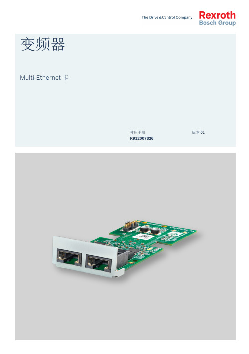
变频器Multi-Ethernet卡版本 01使用手册R912007826Bosch Rexroth AG Multi-Ethernet卡更改过程出版颁发日期备注DOK-RCON0*-XFCX610*MUL-IT01-ZH-P2017.10第一版参考文档如需其他类型或语言的文档, 请联系当地代理商或访问以下网址: 。
版权© 博世力士乐(西安)电子传动与控制有限公司 2017保留所有权利, 也保留包括任何使用、利用、翻印、编辑、转让以及申请知识产权的权利。
责任规格数据仅用于产品说明,如果未在合同中明确规定,不得视为对特性的保证。
本公司保留关于该文档内容和产品可用性的所有权利。
RS-67e4685e2f9bec600a347ea500348fff-1-zh-CN-12Multi-Ethernet卡Bosch Rexroth AG目录目录页数1 安全说明 (1)2 基本介绍 (2)2.1 概要 (2)2.2 工程软件 (3)2.2.1 连接变频器与PC (3)2.2.2 软件升级 (4)2.3 参考文档 (6)3 硬件安装 (7)3.1 硬件说明 (7)3.2 扩展卡的安装 (7)3.3 电缆使用要求 (7)3.4 LED显示 (8)3.5 供电电源 (9)4 基本配置 (10)4.1 协议选择 (10)4.2 通讯通道设置 (11)4.3 过程数据 (12)4.4 设备行规 (14)4.5 故障管理 (16)5 PROFINET IO (17)5.1 协议配置 (17)5.1.1 设备名称 (17)5.1.2 IP设置 (17)5.2 系统配置 (18)5.2.1 GSD文件 (18)5.2.2 IO设备 (19)5.2.3 拓扑 (21)5.2.4 过程数据 (21)5.3 非周期性通讯 (22)5.3.1 原理 (22)5.3.2 模块ID (22)5.3.3 记录索引 (22)5.4 实例说明 (23)DOK-RCON0*-XFCX610*MUL-IT01-ZH-P I页数6 EtherNet/IP .......................................................................................... 246.1 协议配置............................................................................................... 246.2 系统配置............................................................................................... 246.2.1 EDS 文件............................................................................................... 246.2.2 通用设备............................................................................................... 256.2.3 拓扑...................................................................................................... 256.2.4 过程数据............................................................................................... 266.3 非周期性通讯......................................................................................... 276.3.1 消息参数............................................................................................... 276.3.2 错误代码............................................................................................... 286.4 实例说明............................................................................................... 297 SERCOS III ........................................................................................... 307.1 协议配置............................................................................................... 307.2 系统配置............................................................................................... 317.2.1 XML 文件.............................................................................................. 317.2.2 拓扑...................................................................................................... 327.2.3 过程数据............................................................................................... 327.2.4 SERCOS III 控制字和状态字................................................................... 327.3 非周期通讯............................................................................................ 337.4 实例说明............................................................................................... 338 EtherCAT .............................................................................................. 408.1 协议配置............................................................................................... 408.2 系统配置............................................................................................... 408.2.1 配置文件............................................................................................... 408.2.2 模式选择............................................................................................... 418.2.3 拓扑...................................................................................................... 428.2.4 过程数据............................................................................................... 428.3 非周期通讯............................................................................................ 429 Modbus/TCP ........................................................................................ 439.1 协议配置............................................................................................... 439.2 系统配置............................................................................................... 439.3 异常代码............................................................................................... 4410 参数...................................................................................................... 4510.1参数地址 (45)Bosch Rexroth AG 目录Multi-Ethernet 卡IIDOK-RCON0*-XFCX610*MUL -IT01-ZH-PMulti-Ethernet卡Bosch Rexroth AG目录页数10.2 MEP参数 (47)10.2.1 术语和缩写词 (47)10.2.2 参数列表 (47)11 诊断 (51)11.1 LED指示 (51)11.2 警告代码 (53)11.3 故障代码 (54)DOK-RCON0*-XFCX610*MUL-IT01-ZH-P IIIBosch Rexroth AG Multi-Ethernet卡IV DOK-RCON0*-XFCX610*MUL-IT01-ZH-P1 安全说明文档的安全说明中包含特定的警示词(危险、警告、小心或注意),(根据ANSI Z535.6-2011)必要时还包括一个安全提示符号。
博世力士乐多路换向阀ED多路阀手册说明书
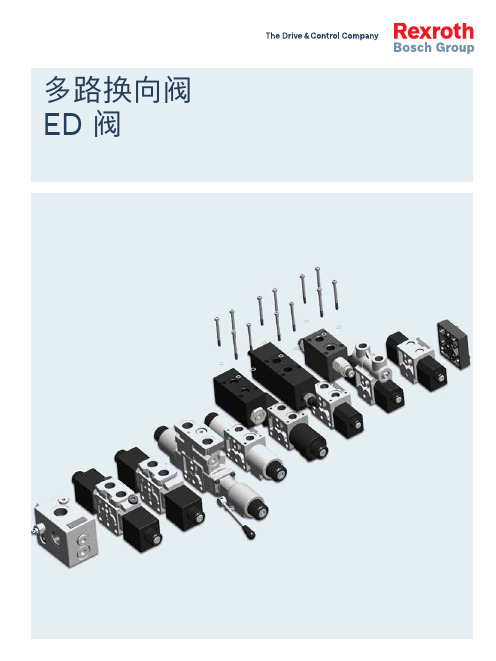
多路换向阀ED 阀2ED 多路阀 | | ED 多路阀 3博世力士乐推出“多路换向阀 — ED 多路阀手册”:根据具体应用,使用该手册可以简化多路阀元件选型。
我们的目标是制作一种非常方便查阅的材料(该材料不能代替产品样本)。
由于我们拥有完整的产品系列、清晰的型号体系以及各种可选项,该手册能有效指导用户选择所需的元件。
ED 多路阀可以替代传统的“六通换向阀”,同时 ED 多路阀元件可以“无限度”地进行组合,以满足用户的各种要求并提高设备的性能。
ED 多路阀手册的编写正是建立在这种 “ 片式 ED 多路阀”的理念基础之上。
ED 多路阀手册帮助用户完成多路阀元件的选型配置,构建控制执行机构(马达或油缸)的开关和比例电磁多路换向阀。
根据液压回路类别,参照该手册可以很容易地选择合适的多路阀元件以构建能够满足回路要求的系统。
手册中也包括了一些我们可以开发的适用于不同回路或应用的液压元件。
如果系统或应用对单联流量要求超过 80L/min,可以采用 ED 多路阀与 M4-12 / M4-15 阀组合使用的方案,构成“组合控制方案”。
应用:f 1. 随车起重机 f 2. 全路面起重机 f 3. 爬梯高空作业车 f 4. 车载高空作业车 f 5. 高空作业车 f 6. 叉车 f 7. 喷药车 f 8. 联合收割机 f 9. 伸缩臂叉车 f 10. 挖掘装载机 f 11. 挖掘机 f 12. 钻机 f 13. 垃圾车 f14. 扫地车简介应用及产品图片EDC 多路阀组合控制方案M4 + EDC + EDB 多路阀组合控制方案M4 + EDC + ED 多路阀EDD 多路阀图 1图 2从图 1 和图 2 中,我们可以看出 ED 多路阀与传统六通换向阀的区别。
对于传统控制阀(图 1),油泵通过阀的中位泄荷,而 ED 多路阀只有 4 个油口,因此需要专门的泄荷方法。
最常用的泄荷方法是采用如图 2 所示的 2 位 2 通电磁阀,或者使用逻辑元件。
博世力士乐 CS351 CC-CS351 紧凑系统操作手册说明书
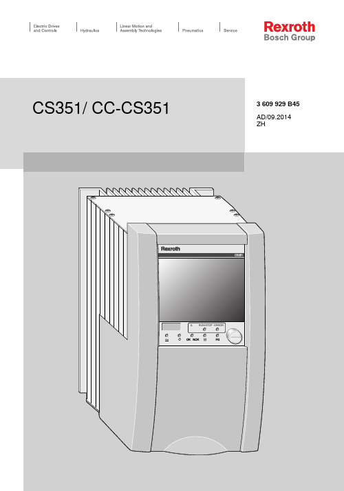
2/52博世力士乐股份公司CS351/CC-CS351|3609929B45/2014-09CS351 | 3609929B45/2014-09博世力士乐股份公司3/54目录1关于本文档 (05)2一般安全说明 (06)3交付范围 (09)4产品说明 (10)5运输和存储 (31)6装配 (32)7调试 (34)8操作 (38)9维护和修理 (40)10废弃 (46)11拆卸和更换 (47)12处置 (48)13扩展和转换 (48)14故障诊断 (48)15技术数据 (49)16服务与销售 (52)语英4/54 博世力士乐股份公司CS351 | 3609929B45/2014-09以上所列数据仅用于对产品进行说明。
我们提供的信息不能作为对某种条件或某种应用适用性的声明。
所提供的信息不能免除用户自行判断和验证的义务。
请注意,我们的产品会经受自然磨损和老化。
© 本文档及其中所列的数据、规格和其它信息为博世力士乐股份公司独家所有。
未经许可,不得将其翻印或提供给第三方。
本文档以 PDF 文件的形式提供。
原始操作说明的翻译。
原始说明以德语制作。
CS351 | 3609929B45/2014-09 博世力士乐股份公司5/54关于本文档英语1关于本文档本手册包含有关 CS351/CC-CS351 紧凑型系统的安全和适当装配、运输、调试、操作、维护、拆卸以及简单故障诊断的重要信息。
有关紧凑型系统中使用的软件说明并不包含在这些说明中。
有关您可能需要的软件和操作的任何信息,请参阅 BS350 操作程序的联机帮助以及随附的 USB 系统记忆棒中的系统文档。
在使用紧凑型系统之前,请完整阅读这些说明,尤其是第 6 页的“一般安全说明”一章。
文档的范围此文档适用于 CS351 和 CC-CS351 紧凑型系统。
需要符合 VDI/VDE 2862 类别 A 文档的拧紧操作可以使用由 ErgoSpin 手持式拧紧机和 CS351E... 紧凑型系统组成的拧紧系统来执行。
Rexroth WV02系列电子操作 产品手册
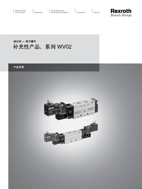
产品手册2Bosch Rexroth AG | Pneumatics换向阀 → 电子操作补充性产品,系列 WV02粗体字标识的材料编号从德国的中心仓库起即可使用,详细信息请见购物篮气动产品-目录,在线PDF,制定于 2011-11-02, © Bosch Rexroth AG,保留更改权利2 x 3/2换向阀, 系列 WV02▶ Qn = 600 l/min ▶ 管式连接 ▶ 压缩空气 接口 出口: G 1/8 ▶ 电子连接: 多芯插头, ISO 15217, C 型 ▶ 手动控制装置: 可锁定6三位五通换向阀, 系列 WV02▶ Qn = 250 - 400 l/min ▶ 管式连接 ▶ 压缩空气 接口 出口: G 1/8 ▶ 电子连接: 多芯插头, ISO 15217, C 型 ▶ 手动控制装置: 未带制动15分气块23盲板243Bosch Rexroth AG | Pneumatics换向阀 → 电子操作2 x 3/2换向阀, 系列 WV02▶ Qn = 600 l/min ▶ 管式连接 ▶ 压缩空气 接口 出口: G 1/8 ▶ 电子连接: 多芯插头, ISO 15217, C 型 ▶ 手动控制装置: 未带制动补充性产品粗体字标识的材料编号从德国的中心仓库起即可使用,详细信息请见购物篮气动产品-目录,在线PDF,制定于 2011-11-02, © Bosch Rexroth AG,保留更改权利00108691结构特点滑阀,零遮盖先导内部密封原理软密封在多线路导线板上的组装PRS-导线板工作压力范围2,2 bar / 10 bar 控制压力最小/最大2,2 bar / 10 bar 环境温度 最小值/最大值+0°C / +50°C 最低/最高介质温度+0°C / +60°C 介质压缩空气颗粒大小 max.5 µm压缩空气中的含油量0 mg/m³ - 5 mg/m³标准化电路接口ISO 15217:2000防护等级带有接线盒 / 插头IP 65暂载率100 %开机时间12 ms 安装螺钉M3材料:外壳铝材, 阳极氧化处理密封氢化-丙烯腈-树胶正面板聚酰胺螺纹管套铝材4Bosch Rexroth AG | Pneumatics换向阀 → 电子操作2 x 3/2换向阀, 系列 WV02▶ Qn = 600 l/min ▶ 管式连接 ▶ 压缩空气 接口 出口: G 1/8 ▶ 电子连接: 多芯插头, ISO 15217, C 型 ▶ 手动控制装置: 未带制动补充性产品粗体字标识的材料编号从德国的中心仓库起即可使用,详细信息请见购物篮气动产品-目录,在线PDF,制定于 2011-11-02, © Bosch Rexroth AG,保留更改权利5Bosch Rexroth AG | Pneumatics换向阀 → 电子操作2 x 3/2换向阀, 系列 WV02▶ Qn = 600 l/min ▶ 管式连接 ▶ 压缩空气 接口 出口: G 1/8 ▶ 电子连接: 多芯插头, ISO 15217, C 型 ▶ 手动控制装置: 未带制动00108692补充性产品粗体字标识的材料编号从德国的中心仓库起即可使用,详细信息请见购物篮气动产品-目录,在线PDF,制定于 2011-11-02, © Bosch Rexroth AG,保留更改权利6Bosch Rexroth AG | Pneumatics换向阀 → 电子操作2 x 3/2换向阀, 系列 WV02▶ Qn = 600 l/min ▶ 管式连接 ▶ 压缩空气 接口 出口: G 1/8 ▶ 电子连接: 多芯插头, ISO 15217, C 型 ▶ 手动控制装置: 可锁定补充性产品粗体字标识的材料编号从德国的中心仓库起即可使用,详细信息请见购物篮气动产品-目录,在线PDF,制定于 2011-11-02, © Bosch Rexroth AG,保留更改权利00108691结构特点滑阀,零遮盖先导内部密封原理软密封在多线路导线板上的组装PRS-导线板工作压力范围2,2 bar / 10 bar 控制压力最小/最大2,2 bar / 10 bar 环境温度 最小值/最大值+0°C / +50°C 最低/最高介质温度+0°C / +60°C 介质压缩空气颗粒大小 max.5 µm压缩空气中的含油量0 mg/m³ - 5 mg/m³标准化电路接口ISO 15217:2000防护等级带有接线盒 / 插头IP 65暂载率100 %开机时间12 ms 安装螺钉M3材料:外壳铝材, 阳极氧化处理密封氢化-丙烯腈-树胶正面板聚酰胺螺纹管套铝材7Bosch Rexroth AG | Pneumatics换向阀 → 电子操作2 x 3/2换向阀, 系列 WV02▶ Qn = 600 l/min ▶ 管式连接 ▶ 压缩空气 接口 出口: G 1/8 ▶ 电子连接: 多芯插头, ISO 15217, C 型 ▶ 手动控制装置: 可锁定补充性产品粗体字标识的材料编号从德国的中心仓库起即可使用,详细信息请见购物篮气动产品-目录,在线PDF,制定于 2011-11-02, © Bosch Rexroth AG,保留更改权利8Bosch Rexroth AG | Pneumatics换向阀 → 电子操作2 x 3/2换向阀, 系列 WV02▶ Qn = 600 l/min ▶ 管式连接 ▶ 压缩空气 接口 出口: G 1/8 ▶ 电子连接: 多芯插头, ISO 15217, C 型 ▶ 手动控制装置: 可锁定00108692_a补充性产品粗体字标识的材料编号从德国的中心仓库起即可使用,详细信息请见购物篮气动产品-目录,在线PDF,制定于 2011-11-02, © Bosch Rexroth AG,保留更改权利9Bosch Rexroth AG | Pneumatics换向阀 → 电子操作二位五通换向阀, 系列 WV02▶ Qn = 500 l/min ▶ 管式连接 ▶ 压缩空气 接口 出口: G 1/8 ▶ 电子连接: 多芯插头, ISO 15217, C 型 ▶ 手动控制装置: 未带制动 ▶ 单稳, 双电磁线圈补充性产品粗体字标识的材料编号从德国的中心仓库起即可使用,详细信息请见购物篮气动产品-目录,在线PDF,制定于 2011-11-02, © Bosch Rexroth AG,保留更改权利00108697结构特点滑阀,零遮盖先导内部密封原理软密封在多线路导线板上的组装PRS-导线板工作压力范围见下表控制压力最小/最大见下表环境温度 最小值/最大值+0°C / +50°C 最低/最高介质温度+0°C / +60°C 介质压缩空气颗粒大小 max.5 µm压缩空气中的含油量0 mg/m³ - 5 mg/m³标准化电路接口ISO 15217:2000防护等级带有接线盒 / 插头IP 65暂载率100 %安装螺钉M3材料:外壳铝材, 阳极氧化处理密封氢化-丙烯腈-树胶正面板聚酰胺螺纹管套铝材10Bosch Rexroth AG | Pneumatics换向阀 → 电子操作二位五通换向阀, 系列 WV02▶ Qn = 500 l/min ▶ 管式连接 ▶ 压缩空气 接口 出口: G 1/8 ▶ 电子连接: 多芯插头, ISO 15217, C 型 ▶ 手动控制装置: 未带制动 ▶ 单稳, 双电磁线圈补充性产品粗体字标识的材料编号从德国的中心仓库起即可使用,详细信息请见购物篮气动产品-目录,在线PDF,制定于 2011-11-02, © Bosch Rexroth AG,保留更改权利制动 ▶ 单稳, 双电磁线圈00108698定 ▶ 单稳, 双电磁线圈00108697结构特点滑阀,零遮盖先导内部密封原理软密封在多线路导线板上的组装PRS-导线板工作压力范围见下表控制压力最小/最大见下表环境温度 最小值/最大值+0°C / +50°C最低/最高介质温度+0°C / +60°C介质压缩空气颗粒大小 max. 5 µm压缩空气中的含油量0 mg/m³ - 5 mg/m³标准化电路接口ISO 15217:2000防护等级带有接线盒 / 插头IP 65暂载率100 %安装螺钉M3材料:外壳铝材, 阳极氧化处理密封氢化-丙烯腈-树胶正面板聚酰胺螺纹管套铝材定 ▶ 单稳, 双电磁线圈定 ▶ 单稳, 双电磁线圈00108698_a未带制动00108703结构特点滑阀,零遮盖先导内部密封原理软密封在多线路导线板上的组装PRS-导线板工作压力范围2,2 bar / 10 bar控制压力最小/最大2,2 bar / 10 bar环境温度 最小值/最大值+0°C / +50°C最低/最高介质温度+0°C / +60°C介质压缩空气颗粒大小 max. 5 µm压缩空气中的含油量0 mg/m³ - 5 mg/m³标准化电路接口ISO 15217:2000防护等级带有接线盒 / 插头IP 65暂载率100 %安装螺钉M3材料:外壳铝材, 阳极氧化处理正面板聚酰胺螺纹管套铝材未带制动未带制动00108704可锁定00108703结构特点滑阀,零遮盖先导内部密封原理软密封在多线路导线板上的组装PRS-导线板工作压力范围2,2 bar / 10 bar控制压力最小/最大2,2 bar / 10 bar环境温度 最小值/最大值+0°C / +50°C最低/最高介质温度+0°C / +60°C介质压缩空气颗粒大小 max.0,5 µm压缩空气中的含油量0 mg/m³ - 25 mg/m³标准化电路接口ISO 15217:2000防护等级带有接线盒 / 插头IP 65暂载率100 %安装螺钉M3材料:外壳铝材密封丙烯树胶正面板聚酰胺螺纹管套铝材可锁定可锁定00108704_a21Bosch Rexroth AG | Pneumatics换向阀 → 电子操作系列 WV02附件粗体字标识的材料编号从德国的中心仓库起即可使用,详细信息请见购物篮气动产品-目录,在线PDF,制定于 2011-11-02, © Bosch Rexroth AG,保留更改权利接线盒, 系列 CN1▶ ISO 15217:2000 ▶ 接线盒, C 型P894_220环境温度 最小值/最大值-40°C / +90°C 防护等级IP 6500138876接线盒,带电缆线, 系列 CN1▶ ISO 15217:2000 ▶ 带电缆 ▶ C 型P894_018环境温度 最小值/最大值-20°C / +80°C 防护等级IP 67导线截面固定螺栓的起始力矩0,4 Nm材料:密封天然橡胶 / 丁二烯橡胶22Bosch Rexroth AG | Pneumatics换向阀 → 电子操作系列 WV02附件粗体字标识的材料编号从德国的中心仓库起即可使用,详细信息请见购物篮气动产品-目录,在线PDF,制定于 2011-11-02, © Bosch Rexroth AG,保留更改权利产品代码183448421218344842131834484214Fig. 1Fig. 200132210001322111) 0° 轴套插件2) 180° 轴套插件23Bosch Rexroth AG | Pneumatics换向阀 → 电子操作系列 WV02附件粗体字标识的材料编号从德国的中心仓库起即可使用,详细信息请见购物篮气动产品-目录,在线PDF,制定于 2011-11-02, © Bosch Rexroth AG,保留更改权利分气块00108728环境温度 最小值/最大值+0°C / +80°C 最低/最高介质温度+0°C / +80°C 介质压缩空气工作压力范围见下表安装螺钉带内六方气动接口(1)的方向侧面的气动接口(3,5)的方向侧面的各个接口分离压缩空气连接尺寸符合 ISO 228-1 标准材料:连接板铝材密封丙烯树胶24Bosch Rexroth AG | Pneumatics 换向阀 → 电子操作系列 WV02附件粗体字标识的材料编号从德国的中心仓库起即可使用,详细信息请见购物篮气动产品-目录,在线PDF,制定于 2011-11-02, © Bosch Rexroth AG,保留更改权利00108730连接 82 和 84:先导排气 。
变频器 VFC 3210 使用手册说明书

变频器VFC 3210版本04使用手册R912006805Bosch Rexroth AG VFC 3210更改过程出版颁发日期备注DOK-RCON04-VFC3210****-IT01-ZH-P2016.04第一版DOK-RCON04-VFC3210****-IT02-ZH-P2016.07第二版DOK-RCON04-VFC3210****-IT03-ZH-P2017.03第三版DOK-RCON04-VFC3210****-IT04-ZH-P2018.05第四版版本匹配表固件使用手册快速启动指南03V12版本01版本0103V14版本02版本0203V20版本03版本0303V26版本04版本04版权© 博世力士乐(西安)电子传动与控制有限公司 2018保留所有权利, 也保留包括任何使用、利用、翻印、编辑、转让以及申请知识产权的权利。
责任规格数据仅用于产品说明,如果未在合同中明确规定,不得视为对特性的保证。
本公司保留关于该文档内容和产品可用性的所有权利。
RS-215f04baecc4f3180a347ea50119e314-4-zh-CN-5Deutsch English FrançaisLebensgefahr beiNichtbeachtung der nachstehendenSicherheitshinweise!Nehmen Sie die Produkte erst dannin Betrieb, nachdem Sie die mit demProdukt gelieferten Unterlagen undSicherheitshinweise vollständigdurchgelesen, verstanden undbeachtet haben.Sollten Ihnen keine Unterlagen inIhrer Landessprache vorliegen,wenden Sie sich an Ihrenzuständigen Rexroth-Vertriebspartner.Nur qualifiziertes Personal darf anAntriebskomponenten arbeiten.Nähere Erläuterungen zu denSicherheitshinweisen entnehmen SieKapitel 1 dieser Dokumentation.Danger to life incase of non‑compliance with thebelow-mentioned safetyinstructions!Do not attempt to install or put theseproducts into operation until youhave completely read, understoodand observed the documentssupplied with the product.If no documents in your languagewere supplied, please consult yourRexroth sales partner.Only qualified persons may workwith drive components.For detailed explanations on thesafety instructions, see chapter 1 ofthis documentation.Danger demort en cas de non‑respect desconsignes de sécurité figurant ci-après !Ne mettez les produits en servicequ’après avoir lu complètement etaprès avoir compris et respecté lesdocuments et les consignes desécurité fournis avec le produit.Si vous ne disposez pas de ladocumentation dans votre langue,merci de consulter votre partenaireRexroth.Seul un personnel qualifié est autoriséà travailler sur les composantsd’entraînement.Vous trouverez des explications plusdétaillées relatives aux consignes desécurité au chapitre 1 de la présentedocumentation.Hohe elektrischeSpannung! Lebensgefahr durchelektrischen Schlag!Betreiben Sie Antriebskomponentennur mit fest installiertemSchutzleiter.Schalten Sie vor Zugriff aufAntriebskomponenten dieSpannungsversorgung aus.Beachten Sie die Entladezeiten vonKondensatoren.High electricalvoltage! Danger to life by electricshock!Only operate drive components witha permanently installed equipmentgrounding conductor.Disconnect the power supply beforeaccessing drive components.Observe the discharge times of thecapacitors.Tensionsélectriques élevées ! Danger de mortpar électrocution !N’exploitez les composantsd’entraînement que si un conducteurde protection est installé de manièrepermanente.Avant d’intervenir sur les composantsd’entraînement, coupez toujours latension d’alimentation.Tenez compte des délais de déchargede condensateurs.GefahrbringendeBewegungen! Lebensgefahr!Halten Sie sich nicht imBewegungsbereich von Maschinenund Maschinenteilen auf.Verhindern Sie den unbeabsichtigtenZutritt für Personen.Bringen Sie vor dem Zugriff oderZutritt in den Gefahrenbereich dieAntriebe sicher zum Stillstand.Dangerousmovements! Danger to life!Keep free and clear of the ranges ofmotion of machines and movingmachine parts.Prevent personnel from accidentallyentering the range of motion ofmachines.Make sure that the drives are broughtto safe standstill before accessing orentering the danger zone.Mouvements entraînant une situationdangereuse ! Danger de mort !Ne séjournez pas dans la zone demouvement de machines et decomposants de machines.Évitez tout accès accidentel depersonnes.Avant toute intervention ou tout accèsdans la zone de danger, assurez-vousde l’arrêt préalable de tous lesentraînements.VFC 3210 Bosch Rexroth AG DOK-RCON04-VFC3210****-IT04-ZH-P IDeutsch English Français Elektromagnetische / magnetischeFelder! Gesundheitsgefahr fürPersonen mit Herzschrittmachern,metallischen Implantaten oderHörgeräten!Zutritt zu Bereichen, in denenAntriebskomponenten montiert undbetrieben werden, ist für obengenannten Personen untersagt bzw.nur nach Rücksprache mit einemArzt erlaubt.Electromagnetic /magnetic fields! Health hazard forpersons with heart pacemakers,metal implants or hearing aids!The above-mentioned persons arenot allowed to enter areas in whichdrive components are mounted andoperated, or rather are only allowedto do this after they consulted adoctor.Champsélectromagnétiques / magnétiques !Risque pour la santé des porteurs destimulateurs cardiaques, d’implantsmétalliques et d’appareils auditifs !L’accès aux zones où sont montés etexploités les composantsd’entraînement est interdit auxpersonnes susmentionnées ou bienne leur est autorisé qu’aprèsconsultation d’un médecin.Heiße Oberflächen(> 60 °C)! Verbrennungsgefahr!Vermeiden Sie das Berühren vonmetallischen Oberflächen (z. B.Kühlkörpern). Abkühlzeit derAntriebskomponenten einhalten(mind. 15 Minuten).Hot surfaces(> 60 °C [140 °F])! Risk of burns!Do not touch metallic surfaces (e.g.heat sinks). Comply with the timerequired for the drive components tocool down (at least 15 minutes).Surfaces chaudes(> 60 °C)! Risque de brûlure !Évitez de toucher des surfacesmétalliques (p. ex. dissipateursthermiques). Respectez le délai derefroidissement des composantsd’entraînement (au moins 15minutes).UnsachgemäßeHandhabung bei Transport undMontage! Verletzungsgefahr!Verwenden Sie geeignete Montage-und Transporteinrichtungen.Benutzen Sie geeignetes Werkzeugund persönliche Schutzausrüstung.Improper handlingduring transport and mounting! Riskof injury!Use suitable equipment for mountingand transport.Use suitable tools and personalprotective equipment.Manipulationincorrecte lors du transport et dumontage ! Risque de blessure !Utilisez des dispositifs de montage etde transport adéquats.Utilisez des outils appropriés et votreéquipement de protection personnel.UnsachgemäßeHandhabung von Batterien!Verletzungsgefahr!Versuchen Sie nicht, leere Batterienzu reaktivieren oder aufzuladen(Explosions- und Verätzungsgefahr).Zerlegen oder beschädigen Sie keineBatterien. Werfen Sie Batterien nichtins Feuer.Improper handling ofbatteries! Risk of injury!Do not attempt to reactivate orrecharge low batteries (risk ofexplosion and chemical burns).Do not dismantle or damagebatteries. Do not throw batteries intoopen flames.Manipulationincorrecte de piles! Risque deblessure!N’essayez pas de réactiver des pilesvides ou de les charger (risqued’explosion et de brûlure par acide).Ne désassemblez et n’endommagezpas les piles. Ne jetez pas des pilesdans le feu.Bosch Rexroth AG VFC 3210 II DOK-RCON04-VFC3210****-IT04-ZH-PEspañol Português Italiano¡Peligro demuerte en caso de no observar lassiguientes indicaciones deseguridad!Los productos no se pueden poneren servicio hasta después de haberleído por completo, comprendido ytenido en cuenta la documentación ylas advertencias de seguridad que seincluyen en la entrega.Si no dispusiera de documentaciónen el idioma de su país, diríjase a sudistribuidor competente de Rexroth.Solo el personal debidamentecualificado puede trabajar encomponentes de accionamiento.Encontrará más detalles sobre lasindicaciones de seguridad en elcapítulo 1 de esta documentación.Perigo de vida emcaso de inobservância das seguintesinstruções de segurança!Utilize apenas os produtos depois deter lido, compreendido e tomado emconsideração a documentação e asinstruções de segurança fornecidasjuntamente com o produto.Se não tiver disponível adocumentação na sua língua, dirija-se ao seu parceiro de vendaresponsável da Rexroth.Apenas pessoal qualificado podetrabalhar nos componentes deacionamento.Explicações mais detalhadasrelativamente às instruções desegurança constam no capítulo 1desta documentação.Pericolo dimorte in caso di inosservanza delleseguenti indicazioni di sicurezza!Mettere in funzione i prodotti solodopo aver letto, compreso e osservatoper intero la documentazione e leindicazioni di sicurezza fornite con ilprodotto.Se non dovesse essere presente ladocumentazione nella vostra lingua,siete pregati di rivolgervi al rivenditoreRexroth competente.Solo personale qualificato puòeseguire lavori sui componenti dicomando.Per ulteriori spiegazioni riguardanti leindicazioni di sicurezza consultare ilcapitolo 1 di questa documentazione.¡Alta tensióneléctrica! ¡Peligro de muerte pordescarga eléctrica!Active sólo los componentes deaccionamiento con el conductorprotector firmemente instalado.Desconecte la alimentación eléctricaantes de manipular los componentesde accionamiento.Tenga en cuenta los tiempos dedescarga de los condensadores.Alta tensão elétrica!Perigo de vida devido a choqueelétrico!Opere componentes de acionamentoapenas com condutores de proteçãoinstalados.Desligue a alimentação de tensãoantes de aceder aos componentes deacionamento.Respeite os períodos de descargados condensadores.Alta tensioneelettrica! Pericolo di morte in seguitoa scosse elettriche!Mettere in esercizio i componenti dicomando solo con conduttore dimessa a terra ben installato.Staccare l'alimentazione prima diintervenire sui componenti dicomando.Osservare i tempi di scarica delcondensatore.¡Movimientospeligrosos! ¡Peligro de muerte!No permanezca en la zona demovimiento de las máquinas ni desus piezas.Impida el acceso accidental depersonas.Antes de acceder o introducir lasmanos en la zona de peligro, losaccionamientos se tienen que haberparado con seguridad.Movimentosperigosos! Perigo de vida!Não permaneça na área demovimentação das máquinas e daspeças das máquinas.Evite o acesso involuntário parapessoas.Antes de entrar ou aceder à áreaperigosa, imobilize os acionamentosde forma segura.Movimentipericolosi! Pericolo di morte!Non sostare nelle zone di manovradelle macchine e delle loro parti.Impedire un accesso non autorizzatoper le persone.Prima di accedere alla zona dipericolo, arrestare e bloccare gliazionamenti.VFC 3210 Bosch Rexroth AG DOK-RCON04-VFC3210****-IT04-ZH-P IIIEspañol Português Italiano¡Camposelectromagnéticos/magnéticos!¡Peligro para la salud de las personascon marcapasos, implantesmetálicos o audífonos!El acceso de las personas arribamencionadas a las zonas de montajeo funcionamiento de loscomponentes de accionamiento estáprohibido, salvo que lo autoricepreviamente un médico.Camposeletromagnéticos / magnéticos!Perigo de saúde para pessoas commarcapassos, implantes metálicosou aparelhos auditivos!Acesso às áreas, nas quais oscomponentes de acionamento sãomontados e operados, é proibidopara as pessoas em cimamencionadas ou apenas apóspermissão de um médico.Campielettromagnetici / magnetici! Pericoloper la salute delle persone portatricidi pacemaker, protesi metalliche oapparecchi acustici!L'accesso alle zone in cui sonoinstallati o in funzione componenti dicomando è vietato per le personesopra citate o consentito solo dopo uncolloquio con il medico.¡Superficiescalientes (> 60 °C)! ¡Peligro dequemaduras!Evite el contacto con las superficiescalientes (p. ej., disipadores decalor). Observe el tiempo deenfriamiento de los componentes deaccionamiento (mín. 15 minutos).Superfícies quentes(> 60 °C)! Perigo de queimaduras!Evite tocar superfícies metálicas (p.ex. radiadores). Respeite o tempo dearrefecimento dos componentes deacionamento (mín. 15 minutos).Superfici bollenti(> 60 °C)! Pericolo di ustioni!Evitare il contatto con superficimetalliche (ad es. dissipatori dicalore). Rispettare i tempi diraffreddamento dei componenti dicomando (almeno 15 minuti).¡Manipulacióninadecuada en el transporte ymontaje! ¡Peligro de lesiones!Utilice dispositivos de montaje y detransporte adecuados.Utilice herramientas adecuadas yequipo de protección personal.Manejo incorreto notransporte e montagem! Perigo deferimentos!Utilize dispositivos de montagem ede transporte adequados.Utilize ferramentas e equipamentode proteção individual adequados.Manipolazioneinappropriata durante il trasporto e ilmontaggio! Pericolo di lesioni!Utilizzare dispositivi di montaggio etrasporto adatti.Utilizzare attrezzi adatti edequipaggiamento di protezionepersonale.¡Manejoinadecuado de las pilas! ¡Peligro delesiones!No trate de reactivar o cargar pilasdescargadas (peligro de explosión ycauterización).No desarme ni dañe las pilas. No tirelas pilas al fuego.Manejo incorreto debaterias! Perigo de ferimentos!Não tente reativar nem carregarbaterias vazias (perigo de explosão ede queimaduras com ácido).Não desmonte nem danifique asbaterias. Não deite as baterias nofogo.Utilizzoinappropriato delle batterie! Pericolodi lesioni!Non tentare di riattivare o ricaricarebatterie scariche (pericolo diesplosione e corrosione).Non scomporre o danneggiare lebatterie. Non gettare le batterie nelfuoco.Bosch Rexroth AG VFC 3210 IV DOK-RCON04-VFC3210****-IT04-ZH-PSvenska Dansk NederlandsLivsfara om följandesäkerhetsanvisningar inte följs!Använd inte produkterna innan duhar läst och förstått dendokumentation och desäkerhetsanvisningar som medföljerprodukten, och följ alla anvisningar.Kontakta din Rexroth-återförsäljareom dokumentationen inte medföljerpå ditt språk.Endast kvalificerad personal fårarbeta med drivkomponenterna.Se kapitel 1 i denna dokumentationför närmare beskrivningar avsäkerhetsanvisningarna.Livsfare vedmanglende overholdelse afnedenståendesikkerhedsanvisninger!Tag ikke produktet i brug, før du harlæst og forstået den dokumentationog de sikkerhedsanvisninger, somfølger med produktet, og overhold degivne anvisninger.Kontakt din Rexroth-forhandler, hvisdokumentationen ikke medfølger pådit sprog.Det er kun kvalificeret personale, dermå arbejde på drive components.Nærmere forklaringer tilsikkerhedsanvisningerne fremgår afkapitel 1 i denne dokumentation.Levensgevaar bij niet-naleving vanonderstaande veiligheidsinstructies!Stel de producten pas in bedrijf nadatu de met het product geleverdedocumenten en deveiligheidsinformatie volledig gelezen,begrepen en in acht genomen heeft.Mocht u niet beschikken overdocumenten in uw landstaal, kunt ucontact opnemen met uw plaatselijkeRexroth distributiepartner.Uitsluitend gekwalificeerd personeelmag aan de aandrijvingscomponentenwerken.Meer informatie over deveiligheidsinstructies vindt u inhoofdstuk 1 van deze documentatie.Hög elektriskspänning! Livsfara genom elchock!Använd endast drivkomponenternamed fastmonterad skyddsledare.Koppla bort spänningsförsörjningenföre arbete på drivkomponenter.Var medveten om kondensatorernasurladdningstid.Elektriskhøjspænding! Livsfare på grund afelektrisk stød!Drive components må kun benyttesmed et fast installeret jordstik.Sørg for at koblespændingsforsyningen fra, inden durører ved drive components.Overhold kondensatorernesafladningstider.Hogeelektrische spanning! Levensgevaardoor elektrische schok!Bedien de aandrijvingscomponentenuitsluitend met vast geïnstalleerdeaardleiding.Schakel voor toegang totaandrijvingscomponenten despanningsvoorziening uit.Neem de ontlaadtijden vancondensatoren in acht.Farliga rörelser!Livsfara!Uppehåll dig inte inom maskinersoch maskindelars rörelseområde.Förhindra att obehöriga personer fårtillträde.Innan du börjar arbeta eller vistasinom drivsystemets riskområdemåste maskinen vara stillastående.Farligebevægelser! Livsfare!Du må ikke opholde dig inden formaskiners og maskindelesbevægelsesradius.Sørg for, at ingen personer kan fåutilsigtet adgang.Stands drevene helt, inden du rørerved drevene eller træder ind i deresfareområde.Risicovollebewegingen! Levensgevaar!Houdt u niet op in hetbewegingsbereik van machines enmachineonderdelen.Voorkom dat personen onbedoeldtoegang verkrijgen.Voor toegang tot de gevaarlijke zonemoeten de aandrijvingen veilig totstilstand gebracht zijn.VFC 3210 Bosch Rexroth AG DOK-RCON04-VFC3210****-IT04-ZH-P VSvenska Dansk NederlandsElektromagnetiska/magnetiska fält! Hälsofara förpersoner med pacemaker, implantatav metall eller hörapparat!Det är förbjudet för ovan nämndapersoner (eller kräver överläggningmed läkare) att beträda områden därdrivkomponenter är monterade och idrift.Elektromagnetiske/magnetiskefelter! Sundhedsfare for personermed pacemakere, metalliskeimplantater eller høreapparater!For disse personer er der adgangforbudt eller kun adgang medtilladelse fra læge til de områder,hvor drive components monteres ogdrives.Elektromagnetische / magnetischevelden! Gevaar voor de gezondheidvan personen met pacemakers,metalen implantaten ofhoorapparaten!Toegang tot gebieden, waarinaandrijvingscomponenten wordengemonteerd en bediend, is verbodenvoor voornoemde personen ofuitsluitend toegestaan na overleg meteen arts.Varma ytor(> 60 °C)! Risk för brännskador!Undvik att vidröra metallytor (t.ex.kylelement). Var medveten om attdet tar tid för drivkomponenterna attsvalna (minst 15 minuter).Varme overflader(> 60 °C)! Risiko for forbrændinger!Undgå at berøre metaloverflader(f.eks. køleelementer). Overholddrive components nedkølingstid(min. 15 min.).Heteoppervlakken (> 60 °C)!Verbrandingsgevaar!Voorkom contact met metalenoppervlakken (bijv. Koellichamen).Afkoeltijd van deaandrijvingscomponenten in achtnemen (min. 15 minuten).Felaktighantering vid transport ochmontering! Skaderisk!Använd passande monterings- ochtransportanordningar.Använd lämpliga verktyg ochpersonlig skyddsutrustning.Fejlhåndteringved transport og montering! Risikofor kvæstelser!Benyt egnede monterings- ogtransportanordninger.Benyt egnet værktøj og personligtsikkerhedsudstyr.Onjuist gebruikbij transport en montage!Letselgevaar!Gebruik geschikte montage- entransportinrichtingen.Gebruik geschikt gereedschap en eenpersoonlijke veiligheidsuitrusting.Felaktighantering av batterier! Skaderisk!Försök inte återaktivera eller laddaupp batterier (risk för explosioneroch frätskador).Batterierna får inte tas isär ellerskadas. Släng inte batterierna ielden.Fejlhåndtering afbatterier! Risiko for kvæstelser!Forsøg ikke at genaktivere elleroplade tomme batterier(eksplosions- og ætsningsfare).Undlad at skille batterier ad eller atbeskadige dem. Smid ikke batterierind i åben ild.Onjuist gebruikvan batterijen! Letselgevaar!Probeer nooit lege batterijen tereactiveren of op te laden(explosiegevaar en gevaar voorbeschadiging van weefsel doorcauterisatie).Batterijen niet demonteren ofbeschadigen. Nooit batterijen in hetvuur werpen.Bosch Rexroth AG VFC 3210 VI DOK-RCON04-VFC3210****-IT04-ZH-PSuomiPolskiČeskýNäidenturvaohjeiden noudattamatta jättämisestä on seurauksena hengenvaara!Ota tuote käyttöön vasta sen jälkeen,kun olet lukenut läpi tuotteen mukana toimitetut asiakirjat jaturvallisuusohjeet, ymmärtänyt ne ja ottanut ne huomioon.Jos asiakirjoja ei ole saatavana omalla äidinkielelläsi, ota yhteys asianomaiseen Rexrothin myyntiedustajaan.Käyttölaitteiden komponenttien parissa saa työskennellä ainoastaan valtuutettu henkilöstö.Lisätietoa turvaohjeista löydät tämän dokumentaation luvusta 1.Zagrożenieżycia w razie nieprzestrzegania poniższych wskazówek bezpieczeństwa!Nie uruchamiać produktów przed uprzednim przeczytaniem i pełnym zrozumieniem wszystkichdokumentów dostarczonych wraz z produktem oraz wskazówek bezpieczeństwa. Należyprzestrzegać wszystkich zawartych tam zaleceń.W przypadku braku dokumentów w Państwa języku, prosimy o skontaktowanie się z lokalnym partnerem handlowym Rexroth.Przy zespołach napędowych możepracować wyłącznie wykwalifikowany personel.Bliższe objaśnienia wskazówek bezpieczeństwa znajdują się wRozdziale 1 niniejszej dokumentacji.Nebezpečí života vpřípadě nedodržení níže uvedených bezpečnostních pokynů!Před uvedením výrobků do provozu si přečtěte kompletní dokumentaci a bezpečnostní pokyny dodávané s výrobkem, pochopte je a dodržujte.Nemáte-li k dispozici podklady ve svém jazyce, obraťte se napříslušného obchodního partnera Rexroth.Na komponentách pohonu smípracovat pouze kvalifikovanýpersonál.Podrobnější vysvětlení kbezpečnostním pokynům naleznete v kapitole 1 této dokumentace.Voimakassähköjännite! Sähköiskun aiheuttama hengenvaara!Käytä käyttölaitteen komponentteja ainoastaan maadoitusjohtimen ollessa kiinteästi asennettuna.Katkaise jännitteensyöttö ennen käyttölaitteen komponenteille suoritettavien töiden aloittamista.Huomioi kondensaattoreiden purkausajat.Wysokienapięcie elektryczne! Zagrożenie życia w wyniku porażenia prądem!Zespoły napędu mogą byćeksploatowane wyłącznie zzainstalowanym na stałe przewodem ochronnym.Przed uzyskaniem dostępu do podzespołów napędu należy odłączyć zasilanie elektryczne.Zwracać uwagę na czas rozładowania kondensatorów.Vysoké elektrickénapětí! Nebezpečí života při zasaženíelektrickým proudem!Komponenty pohonu smí být v provozu pouze s pevněnainstalovaným ochranným vodičem.Než začnete zasahovat do komponent pohonu, odpojte je od elektrického napájení.Dodržujte vybíjecí časy kondenzátorů.Vaarallisia liikkeitä!Hengenvaara!Älä oleskele koneiden tai koneenosien liikealueella.Pidä huolta siitä, ettei muita henkilöitä pääse alueelle vahingossa.Pysäytä käyttölaitteet varmasti ennen vaara-alueelle koskemista tai menemistä.Niebezpieczne ruchy! Zagrożenie życia!Nie wolno przebywać w obszarze pracy maszyny i jej elementów.Nie dopuszczać osób niepowołanychdo obszaru pracy maszyny.Przed dotknięciem urządzenia/maszyny lub zbliżeniem się doobszaru zagrożenia należy zgodnie z zasadami bezpieczeństwa wyłączyćnapędy.Nebezpečnépohyby! Nebezpečí života!Nezdržujte se v dosahu pohybu strojůa jejich součástí.Zabraňte náhodnému přístupu osob.Před zásahem nebo vstupem donebezpečného prostoru bezpečnězastavte pohony.VFC 3210 Bosch Rexroth AGDOK-RCON04-VFC3210****-IT04-ZH-P VIISuomiPolskiČeskýSähkömagneettisia/magneettisia kenttiä! Terveydellisten haittojen vaara henkilöille, joilla on sydämentahdistin, metallinen implantti tai kuulolaite!Yllä mainituilta henkilöiltä on pääsy kielletty alueille, joilla asennetaan tai käytetään käyttölaitteenkomponentteja, tai heidän on ensin saatava tähän suostumus lääkäriltään.Polaelektromagnetyczne / magnetyczne!Zagrożenie zdrowia dla osób z rozrusznikiem serca, metalowymi implantami lub aparatami słuchowymi!Wstęp na teren, gdzie odbywa sięmontaż i eksploatacja napędów jest dla ww. osób zabroniony względnie dozwolony po konsultacji z lekarzem.Elektromagnetická/magnetická pole! Nebezpečí pro zdraví osob s kardiostimulátory,kovovými implantáty nebo naslouchadly!Výše uvedené osoby mají zakázán přístup do prostorů, kde jsoumontovány a používány komponenty pohonu, resp. ho mají povolen pouze po poradě s lékařem.Kuumia pintoja(> 60 °C)! Palovammojen vaara!Vältä metallipintojen koskettamista (esim. jäähdytyslevyt). Noudata käyttölaitteen komponenttien jäähtymisaikoja (väh. 15 minuuttia). Gorącepowierzchnie (> 60 °C)!Niebezpieczeństwo poparzenia!Unikać kontaktu z powierzchniami metalowymi (np. radiatorami).Przestrzegać czasów schładzaniapodzespołów napędów (min. 15minut). Horké povrchy(> 60 °C)! Nebezpečí popálení!Nedotýkejte se kovových povrchů(např. chladicích těles). Dodržujte dobu ochlazení komponent pohonu (min. 15 minut).Epäasianmukainenkäsittely kuljetuksen ja asennuksen yhteydessä! Loukkaantumisvaara!Käytä soveltuvia asennus- ja kuljetuslaitteita.Käytä omia työkaluja jahenkilökohtaisia suojavarusteita. Niewłaściwe obchodzenie się podczas transportu i montażu! Ryzyko urazu!Stosować odpowiednie urządzenia montażowe i transportowe.Stosować odpowiednie narzędzia i środki ochrony osobistej.Nesprávnézacházení při přepravě a montáži!Nebezpečí zranění!Používejte vhodná montážní a dopravní zařízení.Používejte vhodné nářadí a osobníochranné vybavení.Paristojenepäasianmukainen käsittely!Loukkaantumisvaara!Älä yritä saada tyhjiä paristojatoimimaan tai ladata niitä uudelleen (räjähdys- ja syöpymisvaara).Älä hajota paristoja osiin tai vaurioita niitä. Älä heitä paristoja tuleen. Niewłaściwe obchodzenie się z bateriami! Ryzyko urazu!Nie próbować reaktywować i nie ładować zużytych baterii(niebezpieczeństwo wybuchu orazpoparzenia żrącą substancją).Nie demontować i nie niszczyćbaterii. Nie wrzucać baterii do ognia.Nesprávnézacházení s bateriemi! Nebezpečízranění!Nepokoušejte se znovu aktivovat nebodobíjet prázdné baterie (nebezpečívýbuchu a poleptání).Nerozebírejte ani nepoškozujte baterie. Neházejte baterie do ohně.Bosch Rexroth AG VFC 3210VIII DOK-RCON04-VFC3210****-IT04-ZH-P。
Rexroth IndraDrive Cs ACS01 伺服驱动器 产品手册说明书
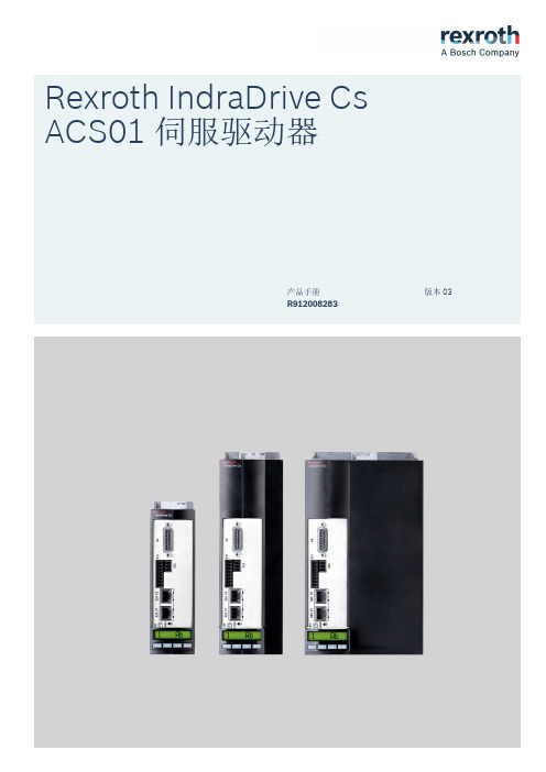
Rexroth IndraDrive Cs ACS01伺服驱动器版本03产品手册R912008283Rexroth IndraDrive Cs ACS01伺服驱动器产品手册DOK-INDRV*-ACS01******-PR03-ZH-PRS-6d0559b3a9217a2a0a347e8600d30991-3-zh-CN-7●Rexroth IndraDrive Cs 系统概述●Rexroth IndraDrive Cs 系统组件组合方式说明●Rexroth IndraDrive Cs 系统组件选择●操作规范●系统特性应用说明出版颁发日期备注012020-01第一版022020-04功能新增032020-06参数更新版权© 博世力士乐(西安)电子传动与控制有限公司 2020保留所有权利, 也保留包括任何使用、利用、翻印、编辑、转让以及申请知识产权的权利。
责任规格数据仅用于产品说明,如果未在合同中明确规定,不得视为对特性的保证。
本公司保留关于该文档内容和产品可用性的所有权利。
题目文件类型文件类型代号内部存档附注文件用途更改过程Rexroth IndraDrive Cs ACS01伺服驱动器Rexroth IndraDrive Cs ACS01伺服驱动器 I目录目录页数1 系统介绍 (1)1.1 Rexroth IndraDrive Cs 系列 (1)1.1.1 概述–Rexroth IndraDrive Cs (1)1.1.2 行业应用 (2)1.1.3 特性 (3)1.2 系统配置 (5)1.2.1 系统结构 (5)1.2.2 驱动器组件 (6)2 安全使用说明 (9)2.1 合理使用 (9)2.1.1 使用须知 (9)2.1.2 应用场合 (9)2.2 不当使用 (10)2.3 使用安全说明 (10)2.3.1 安全使用要求 (10)2.3.2 使用不当引发的危险 (10)2.3.3 与电气元件和外壳接触的防护 (10)2.3.4 危险动作的防护 (11)2.3.5 与高温部件接触的防护 (12)2.3.6 电池安全 (12)2.4 警示词和安全提示符号 (13)3 组件组合 (15)3.1 各组件简介 (15)3.1.1 ACS01---简要说明及设计构成 (15)3.2 配置驱动系统 (15)3.2.1 伺服驱动器 (15)3.2.2 设备功能 (16)3.2.3 电机 (16)3.2.4 电机电缆 (21)3.3 安装条件 (21)3.3.1 安装条件与操作环境 (21)3.3.2 控制柜设计结构与散热 (24)3.4 机械项目规划 (25)3.4.1 驱动器 (25)3.5 电气项目规划 (31)3.5.1 连接图 (31)3.5.2 控制电压项目规划 (32)3.5.3 电源连接电源电压 (36)3.5.4 直流母线耦合 (60)3.6 验收测试及认证 (67)R912008283_版本03 Bosch Rexroth AG页数4供货、标签、运输及存放 (69)4.1 供货................................................................................... 694.1.1 出厂测试.............................................................................. 694.1.2 用户测试.............................................................................. 694.2 标签................................................................................... 704.2.1 铭牌.................................................................................. 704.2.2 包装清单.............................................................................. 714.3 组件运输............................................................................... 724.4组件存放 (72)5安装 (73)5.1 控制柜内安装ACS01...................................................................... 735.2 电气连接............................................................................... 745.2.1 连接图................................................................................ 745.2.2 连接点................................................................................ 755.2.3 板载连接点............................................................................ 765.2.4设计与安装过程中的电磁兼容措施 (96)6组件参数 (105)6.1 控制单元.............................................................................. 1056.1.1 EC-多类型编码器接口.................................................................. 1056.1.2 ET-多协议实时以太网网口.............................................................. 1296.1.3 数字量输入/输出...................................................................... 1356.1.4 电压型模拟量输入..................................................................... 1406.1.5 电流型模拟量输入..................................................................... 1416.1.6 模拟量输出........................................................................... 1416.1.7 继电器触点........................................................................... 1426.2 控制面板.............................................................................. 1436.2.1 设计................................................................................. 1436.3 电源.................................................................................. 1446.3.1 控制电压............................................................................. 1446.3.2 电源电压............................................................................. 1456.3.3 直流母线............................................................................. 1496.3.4 集成制动电阻......................................................................... 1516.3.5逆变器 (151)7电缆、配件及附加组件 (155)7.1 概述.................................................................................. 1557.1.1 电缆................................................................................. 1557.1.2 配件................................................................................. 1557.1.3 附加组件............................................................................. 1567.2 配件.................................................................................. 1577.2.1 安装及配件连接(HAS09).............................................................. 1577.2.2 直流母线连接器(RLS0778/K06)........................................................ 1637.2.3RKB0013,以太网通讯 (164)II 目录Rexroth IndraDrive Cs ACS01伺服驱动器Bosch Rexroth AG R912008283_版本03Rexroth IndraDrive Cs ACS01伺服驱动器 III目录页数7.3 附加组件 (165)7.3.1 电源滤波器NFD / NFE (165)7.3.2 电源电抗器 (168)7.3.3 HLR外部制动电阻 (172)7.3.4 直流侧电容单元HLC (179)8 环境保护及废弃处置 (183)8.1 环境保护 (183)8.2 废弃处置 (183)9 服务与支持 (185)10 附录 (187)10.1 电缆横截面及保险丝尺寸选型 (187)10.2 测量泄露电容 (194)10.3 电容泄露 (195)10.3.1 电机电容泄露 (195)10.3.2 电力电缆电容泄露 (196)索引 (199)R912008283_版本03 Bosch Rexroth AGIV Rexroth IndraDrive Cs ACS01伺服驱动器Bosch Rexroth AG R912008283_版本03Rexroth IndraDrive Cs ACS01伺服驱动器 1/201系统介绍1 系统介绍1.1 Rexroth IndraDrive Cs 系列1.1.1 概述–Rexroth IndraDrive Cs表格1-1:Rexroth IndraDrive Cs 系列组件R912008283_版本03 Bosch Rexroth AG1.1.2行业应用通用自动化、搬运、组装自动化组装及搬运系统码垛系统、取放系统、物流......机床小型机(例如木材加工)、辅机......食品及包装行业灌装及密封、码垛、装箱、封箱、贴标......印刷机械标签打印、贴标、数字印刷、定位......半导体行业半导体/晶圆生产、处理、金属化、清洗、太阳能电池生产......表格1-2:目标应用2/201系统介绍Rexroth IndraDrive Cs ACS01伺服驱动器Bosch Rexroth AG R912008283_版本031.1.3 特性功能特性●结构紧凑●防护等级IP20●具有存储和控制功能的操作面板●多类型编码器接口支持多种主流编码器(ACUROlink、HIPERFACE®、EnDat2.1、EnDat2.2、SSI、TTL、 sin/cos 、旋转变压器、MS2N 编码器、MSC编码器 )●直流母线连接●1个模拟量输入 (14位, ±10 V)●8个数字量输入–2个探针输入–1个组合式数字量端口,可配置为数字量输入或输出●可调节的风扇控制●集成制动电流测量和监控●电机输出端绕组短路触发停机保护机制●支持MSC永磁同步伺服电机●霍尔传感器适配盒SHL03.1,用于操作带有数字霍尔传感器的MCL直线电机性能特征规格(宽:50 mm;高:215 mm)规格(宽:70 mm;高:268 mm)规格(宽:130 mm;高:268 mm)ACS1-W00...→0818283654主电源V 3 AC 200 … 500 V最大输出电流(4kHz)A rms818283654表格1-3:ACS01伺服驱动器规格参数Rexroth IndraDrive Cs ACS01伺服驱动器 3/201系统介绍R912008283_版本03 Bosch Rexroth AG接口概述●兼容IndraDrive 平台●支持以下协议的实时以太网通讯:–sercos III –EtherCAT(SoE)–EtherCAT(CoE)–PROFINET IO –EtherNet/IP●多类型编码器接口●模拟量输入●可自由配置的数字量输入/输出可用编码器可用编码器供电电压为5 V 和12 V 的编码器:●MSC 电机编码器●MSK 电机编码器●MS2N 电机编码器●ACUROlink 编码器●1V pp 正弦编码器,HIPERFACE®●1V pp 正弦编码器,EnDat 2.1、EnDat 2.2●1V pp 正弦编码器(配置参考信道)●省线式TTL 编码器●SSI●组合式编码器SSI(SSI 及1V pp 正弦编码器)●旋转变压器●SHL02.1霍尔传感器适配盒●数字霍尔传感器与SHL03.1霍尔传感器适配盒可配合使用4/201系统介绍Rexroth IndraDrive Cs ACS01伺服驱动器Bosch Rexroth AG R912008283_版本031.2系统配置1.2.1系统结构*可选项24V 控制电压COM 通讯DST 自耦变压器F 保险丝ACS01伺服驱动器HLC 直流母线电容单元(用于连接直流母线的设备)HLR 外部制动电阻HNL 电源电抗器NF 电源滤波器K1外部电源接触器M 电机RB内部制动电阻(位于驱动器后方)插图1-1:Rexroth IndraDrive Cs 驱动系统系统介绍系统介绍1.2.2 驱动器组件ACS01 伺服驱动型号系统介绍表格1-4:ACS01型号说明HAP01 键盘图示插图1-2:HAP01 键盘型号表格1-5:HAP01型号说明系统介绍2安全使用说明2.1合理使用2.1.1使用须知Bosch Rexroth 产品代表着先进的开发和制造水平。
博世力士乐伺服泵SvP安装手册(新软件版本V4 14)_V01
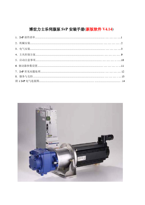
Type SvP-SF-1X/33S2-MA SvP-SF-1X/48S2-MA SvP-SF-1X/60S2-MA SvP-SF-1X/75S2-MA SvP-SF-1X/100S2-MA SvP-SF-1X/120S2-MA SvP-SF-1X/150S2-MA SvP-SF-1X/190SP2-MA
X31/X32:数字/模拟量输入和输出
1. 当驱动器处于AU状态时,使能X31.3(24V高电平有效) , 才能使伺服泵处于运行状态! 2. 3. 4. 5. 6. 泵启动信号通过操作台(PLC)上按钮进行控制 X31.4/X31.5: 选择不同种PID参数时才需要连接, 一般情 况下不需要连接 X31.6 实现伺服泵组主从控制模式切换,默认情况下为主 泵模式(0V), 当工作为从泵模式时,需连接24V; X31.7 用于激活泵的泄漏补偿功能, (24V高电平有效) X32.6可以实现电机风扇开关控制: 若连接,需要电源和风扇之间加继电器实现: 注意到达设定温度时输出信号由1转为0(低电平有效) , 此时需要启动风扇。 ——电机风扇也可长期处于运行状态。 7. 8. X32.7/X32.8为驱动器故障输出和复位信号,连接到PLC 的I/O口 X32.9 为双泵开关信号 , 通过对比实际压力值和设定压 力阀值,实现不同控制信号的输出
直流高压 请勿连接
24V
断路器(A) HCS02.1E-W0028 HCS02.1E-W0054 HCS02.1E-W0070 HCS03.1E-W0070 HCS03.1E-W0100 HCS03.1E-W0150 HCS03.1E-W0210 50 75 100 125 200 200 300
输入电线[mm2] 4 10 10 16 25 25 35
博世力士乐 CVF-MN3 系列迷你型单相小功率变频调速器使用说明书

版本号:MN-0003前言感谢您选用博世力士乐电子传动与控制(深圳)有限公司的CVF-MN3系列迷你型单相小功率变频调速器。
为充分发挥本产品的卓越性能及确保使用者和设备的安全,在您使用之前,请详细阅读本手册。
本手册为随机发送的附件,使用后务请妥善保管,以备对变频器进行检修和维护时使用。
如对本变频器的使用存在疑难或有特殊要求,请随时联络本公司的各地办事处或经销商,也可直接与本公司售后服务中心联系。
本手册内容如有变动,恕不另行通知。
欢迎选用本公司的其它系列变频调速器:CVF - G3/G2 系列通用型变频调速器CVF - P3/P2 系列风机、水泵专用型变频调速器CVF - ZS 系列注塑机专用型变频调速器CVF - ZC 系列注塑一体化柜机CVF - LS1 系列拉丝机专用型变频调速器CVF - LY1 系列络筒机/印花机专用型变频调速器CVF - S1 系列单相小功率变频调速器CVF - V1 系列高性能矢量型变频调速器目录Array1. 注意事项 ........................................1.1 安全注意事项...............................1.2 使用范围...................................1.3 使用注意事项...............................1.4 报废注意事项...............................2.购入检查及变频器的型号与规格....................2.1 购入检查...................................2.2 变频器型号说明.............................2.3 变频器的铭牌数据...........................2.4 系列型号说明...............................2.5 产品技术指标及规格..........................3.变频器的安装....................................3.1 安装环境要求...............................3.2 安装方向与空间.............................3.3 盖板的拆卸和安装............................3.4 变频器的安装尺寸............................4.变频器的配线....................................4.1 配线注意事项...............................4.2 控制回路端子...............................4.3 主回路端子台配线图.........................4.4 推荐使用电器规格............................4.5 系统配线图 ................................4.6 变频器的基本配线图.........................5.面板操作........................................5.1 名词术语说明...............................5.2 面板布局...................................5.3 面板功能说明...............................5.4 键盘操作方法...............................6.变频器的运行....................................6.1 变频器的初始设置...........................6.2 变频器的简单运行...........................7.功能参数一览表...................................7.1 基本运行参数(b参数)......................7.2 中级运行参数(L参数)......................7.3 高级运行参数(H参数).....................7.4 状态监控参数一览表..........................8. 功能详细说明 ....................................8.1 基本运行参数(b参数).....................8.2 中级运行参数(L参数).....................8.3 高级运行参数(H参数).....................9. 故障诊断与对策 ..................................9.1 保护功能及对策.............................9.2 故障记录查询...............................9.3 故障复位...................................10. 维护与保养 .....................................10.1 日常检查与保养.............................10.2 易损部件的检查与更换.......................10.3 存放及保修.................................11. 使用范例 .......................................11.1 面板控制起、停,面板电位器设置频率..........11.2 外部控制方式、外部电压设定频率..............11.3 多段速运行、外部控制方式...................11.4 可编程多段速控制...........................11.5 多台变频器的连动运行(群组控制)...........附录RS485通讯协议.......................................1. 注意事项为确保您的人身、设备及财产的安全,在使用变频器之前,请您务必阅读本章内容,并在以后的搬运、安装、运行、调试与检修过程中遵照执行。
力士乐HNC100(3系列)英文手册

1/20Digital axis controlType VT-HNC100Component series 3XRE 30139/11.10Replaces: 05.10Table of contentsH7642Content PageFeatures 2Ordering code3Software project planning4Overview of the controller functions 5System overview6System overview, interfaces 7Technical data 8 to 11Pinout12 to 16Unit dimensions17Project planning / Maintenance instructions / Additional information18The SERCOS variant formerly described in this data sheet can now be found in data sheet 30159.FeaturesThe digital axis control VT-HNC100...3X is a programma-ble NC control for up to four controlled axes. It complies with the specific requirements for closed-loop control of hydraulic drives.The VT-HNC100...3X is designed for being used in rough in-dustrial environments as regards to interference immunity, mechanical vibration, shock, and climate resistance.Fields of application– Machine tools– Plastics processing machines– Special machines– Presses– Transfer systemsTechnology functions– Sequence programming– Positioning– Pressure/force control– Differential pressure control– Synchronization– Curves– CamsHydraulic axes– Measurement system:• Incremental or absolute (SSI)• Analog 0 to ±10 V and 4 to 20 mA– Actuating variable output voltage or current– Freely configurable controller variants• Position/pressure/force/velocity controller• Path-dependent braking• Substitutional closed-loop control (position/force)• Synchronization control of up to 4 axes also in groups Programming– User programming using a PC– NC language with subroutine technology and conditional jumps– 1 NC program per axis for functional sequences– 1 axes-spanning auxiliary routine– Variable setting of the NC processing velocity– Variable setting of the controller scan timesOperation– Comfortable administration of the machine and measuring data on a PCProcess connection– Digital inputs and outputs,– Analog inputs and outputs,– PROFIBUS DP, PROFIBUS DP in Motorola format, CANopen for the communication with a superior control (for CANopen, there is no standard EDS file available)– PROFINET RTAssembly– Top hat rail 35 mmCE conformity– CE conformity according to EMC directive 2004/108/EC and EMVG (Act on electro-magnetic compatibility of operat-ing media) from February 26, 2008Applied harmonized standards:EN 61000-6-2:2005EN 61000-6-3:2007More information/hnc100Ordering codeVT-HNC100= Serial unitVersion Compact for 1 axis with SSI sensor= C Version for 1 hydraulic axis = 1Version for 2 hydraulic axes = 2Version for 3 hydraulic axes = 3Version for 4 hydraulic axes= 4Component series 30 to 39= 3X(30 to 39: unchanged technical data and pinout)Option000 = without synchronizationG02 = Synchronization 2-axis version G03 = Synchronization 3-axis version G04 = Synchronization 4-axis version00 = No fitting E0 =TCP/IP 1)Position transducer 2)I = Incremental/SSI (standard)S = SSI, only for design “C = Compact”Bus connection P = PROFIBUS DPC = CANopenN =PROFINET RT 3)VT-HNC1003XIncluded within the scope of delivery:Mating connector for– X1S (Type Phoenix Mini Combicon 3-pole),– X2D (Type Phoenix Micro Combicon 8-pole or Phoenix Mini Combicon 12-pole), – X2A (Type Phoenix Micro Combicon 8-pole or HD-SUB 15-pole),– X8M (Type Phoenix Micro Combicon 8-pole or HD-SUB 15-pole)Recommended accessories (can be ordered separately)DescriptionMaterial number Interface cable RS232 (1:1), length 3 m R900776897USB-RS232 converterR901066684Cable set VT17220-1X/HNC100-3X, length 2 m,for analog signals (connection X2A) or digital position measurement systems (connec-tion X8M) with HD connector and open breakout cable for:VT-HNC100-1-3X, VT-HNC100-2-3X, VT-HNC100-3-3X, VT-HNC100-4-3XR901189300Cable set VT17220-1X/HNC100-3X length 2 m,for analog signals (connection X2A) or digital position measurement systems (connec-tion X8M) with FK-MC connector and open breakout cable for VT-HNC100-C-3X R901189302Plug-in connector type 6ES7972-0BA41-0XA0 for PROFIBUS DPR9000501521) Only in connection with PROFIBUS DP for 1, 2 and 4 axisversions2) All axis electronics are fitted with the same position trans-ducer analysis3) Only for 1, 2 and 4 axis versions, not for the compact versionVersions without bus connection are not available.Order options “N” and “E0” for 3 axis version are being prepared.Standard types TypeMaterial number VT-HNC100–C–3X/P-S-00/000R901134618VT-HNC100-1–3X/P-I-00/000R901134614VT-HNC100-2–3X/P-I-00/000R901108539VT-HNC100-3–3X/P-I-00/000R901134620VT-HNC100-4–3X/P-I-00/000R901108538Software project planningProject planningDeveloping application-specific data sets forms the basis for the function of the VT-HNC100...3X. These data sets are gen-erated on the PC and sent to VT-HNC100...3X. The connec-tion of user program and data sets is called project. This soft-ware project planning is implemented according to fix steps: 1. The tasks of the VT-HNC100...3X are defined and recorded in a flow chart. In this connection, the meaning of the inputs and outputs and the used parameters is defined.2. The functions of the flow chart are implemented in a series of NC commands.3. The machine data (selection of transducers and controllers) and the parameters of the NC program are defined.4. The data is sent to the VT-HNC100...3X.5. The setting and the program sequence are optimized at the machine.For detailed information on the generation of a project please refer to the document “First steps”.PC programs “WIN-PED 7” and “WIN-PED 6”For the implementation of the project planning tasks, two WIN-PED programs are available to the user.WIN-PED 7 is suitable for all HNC variants mentioned in this document except for CANopen.WIN-PED 6 is suitable for all HNC variants mentioned in this document except for the options PROFINET RT and PROFIBUS DP with TCP/IP.Projects generated with WIN-PED 6 are not compatible with WIN-PED 7 and vice-versa.Scope of delivery for WIN-PED:– Comfortable dialog functions for setting the machine data online or offline– NC editor with integrated syntax test and program compiler – Support for the definition of the parameters used in the NC program– Dialog window for setting the parameter values online– Comprehensive options for displaying process variables, digital inputs, outputs, and markers– Recording and graphical presentation of up to 16 process variables with great selection of trigger options– Dialog for the graphical definition of special functions (de-termination of the function via polygonal sequence)– Bus manager for the configuration of data exchange (PROFIBUS DP, PROFINET RT) with superior control System requirements:– IBM PC or compatible system– Windows XP for WIN-PED 6– Windows XP or Windows 7 for WIN-PED 7– Random access memory (512 MB recommended)– 100 MB free hard disk capacity as per control type– RS 232 interface for the connection of VT-HNC100...3X, for the PROFINET RT or PROFIBUS DP, also the network interface TCP/IP can be usedNote:The WIN-PED 6/WIN-PED 7 is not included in the scopeof delivery. It can be downloaded from the Internet free of charge, or ordered as CD, Material number R900725471! Download in the Internet: /hnc100 Inquiries: support.nc-systems@boschrexroth.deOverview of the controller functionsPosition controller:– PDT1 controller– Linear amplification characteristic curve– Direction-dependent gain adaptation– Gain modification via the NC program possible– Adaptation of the valve characteristic curve– Fine positioning– Residual voltage principle– Compensation of zero point errors– State feedback via• Pressure,• Pressure differential• Position– Command value provision– Limitation of the actuating variable via the NC program – “Path-dependent braking”– Intermediate electronics when using commercially available NC controls– Synchronization control Pressure/force controller:– PIDT1 controller– I component switchable via window– Pressure differential analysis– Own scan timeVelocity controller:– PI controller– I component switchable via windowSynchronization controller (up to 4 axes):– Master-slave principle– Mean principleMonitoring functions:– Dynamic tracking error monitoring– Traversing range limits (electronic limit switches)– Cable break monitoring for incremental and SSI encoder – Cable break monitoring for sensors with output 4 to 20 mA6/20 Bosch Rexroth AG HydraulicsVT-HNC100...3X RE 30139/11.10System overview(example)Digital inputs/outputs or bus system(PROFIBUS DP, CANopen, PROFINET RT)Superior control (PLC or PC) and visualization (HMI)PC PLC HMIGlobal busCPU + 4 axes VT-HNC100-4-3XCPU + 3 axes VT-HNC100-3-3XCPU + 2 axes VT-HNC100-2-3XCPU + 1 axis VT-HNC100-1-3XCompact 1 axis VT-HNC100-C-3X712635System overview, interfaces (example)1 Single-rod cylinder2 Integrated position measurement system3 Proportional servo valve with integrated control electronics4 VT-HNC100-1-3X/N...5 Connection cable6 Pressure transducer7 Sandwich plate isolator valve (with plug-in switching amplifier)Operating voltage 1)UB 18 to 30 VDC, residual ripple < 1.5 VppCurrent consumption at 24 VDC I approx. 500 mA Processor32 bit power PC Analog inputs (AI):– Voltage input (reference to AGND - Analog ground)• Channel number1• Input voltage UE max +12 V to –12 V (+10 V to –10 V measurable)• Input resistance RE 200 kΩ ± 5 %• Resolution 5 mV• Non-linearity< 0.2 %• Calibration tolerance 2)max. 40 mV (with factory settings)– Current inputs• Channel number2• Input current IE 4 mA to 20 mA• Input resistance RE 225 Ω at 20 °C (100 Ωmeasuring resistance)• Leakage current IV 0.1 to 0.4 % (at 100 Ω between pin 2 or pin 3 (Cin1+ or Cin2+) and “AGND”• Resolution 5 µA– Voltage supply for analog sensors via the VT-HNC100-C-3X U UBat X2A, Pin 7 (+24 Vsens)Analog outputs (AO):– Voltage outputs• Channel number2• Output voltage Unom –10 V to +10 V (max. –10.7 V to +10.7 V)• Output current Imax ±10 mA• Load Rmin1 kΩ– Resolution 1.25 mV – Non-linearity• In the range –9.5 V to +9.5 V< 0,1 %• In the range –10 V to –9.5 V and +9.5 V to +10 V< 0,2 % Technical data VT-HNC100-C-3X (Compact)1) If a 24 V transducer supply is implemented directly via theVT-HNC100...3X (supply voltage is looped in), the trans-ducer specification has to be observed.2) If the factory settings are insufficient, the measurement technology can be calibrated on site via software in asystem-specific way.Interface for WIN-PED 6, WIN-PED 7RS232Bus interface PROFIBUS DP (max. 12 MBaud according to IEC 61158), CANopenGate inputs (DI)Quantity 4Logic level log 0 (low) ≤ 5 V; log 1 (high) ≥ 10 V to U B ,I e = 20 mA at U B = 24 VPort Flexible conductor up to 1.5 mm 2Gate outputs (DO)Quantity 2Logic level log 0 (low) ≤ 2 V; log 1 (high) ≤ U B ; I max = 20 mA,Maximum load capacity C = 0.047 µF Port Flexible conductor up to 1.5 mm 2Reference potential for all signals DGNDDigital position transducers (encoders):– SSI transducer (Due to the higher control quality, an SSI transducer with clock synchronization should be used.) • Coding Gray-Code • Data width Adjustable up to max. 28 Bit • Line receiver / line driver RS485 • Voltage supply via the VT-HNC100-C-3X U U B – Reference potential for all signals EGND Dimensions See page 16AssemblyTop hat rail TH 35-7.5 or TH 35-15 according to EN 60715Admissible operating temperature range ϑ0 to 50 °C Storage temperature rangeϑ–20 to +70 °CProtection class according to EN 60529:1991IP 20Weight:m 440 gCE conformitySee page 2Further technical details upon request.Note!Information on the environment simulation testing for the areas EMC (electromagnetic compatibility), climate and mechani-cal load see data sheet 30139-U.Technical data VT-HNC100-C-3X (Compact) continuedOperating voltage 1)UB 18 to 30 VDC, residual ripple < 1.5 VppCurrent consumption at 24 VDC I 1 to 4 A (depending on the HNC variant and the additionallysupplied components)Processor32 bit power PCAnalog inputs (AI) per axis electronics:– Voltage inputs (differential inputs)• Channel number2• Input voltage UE max +12 V to –12 V (+10 V to –10 V measurable)• Input resistance RE 200 kΩ ± 5 %• Resolution 5 mV• Non-linearity< 0.2 %• Calibration tolerance 2)max. 40 mV (with factory settings)– Current inputs• Channel number2• Input current IE 4 mA to 20 mA• Input resistance RE 350 Ω at 20 °C (100 Ωmeasuring resistance)• Leakage current IV 0.1 to 0.4 %• Resolution 5 µA– Voltage supply for analog sensors via the VT-HNC100...3X U UBat X2A1 to X2A4, Pin 14 (+24 Vsens)Analog outputs (AO) per axis electronics: 3) 2 (1) – Non-linearity• In the range –9.5 V to +9.5 V< 0.1 %• In the range –10 V to –9.5 V and +9.5 V to +10 V< 0.2 %– Voltage output• Output voltage Unom –10 V to +10 V (max. –10.7 V to +10.7 V)• Output current Imax ±10 mA• Load Rmin 1 kΩ• Residual ripple±60 mV (without noise)• Resolution 1.25 mV– Current output• Output current Standardized Inom 4 mA to 20 mA• Load Rmax 500 Ω• Resolution0,625 μA Technical data VT-HNC100-...-3X (CPU + axis electronics)1) If a 24 V transducer supply is implemented directly via theVT-HNC100...3X (supply voltage is looped in), the trans-ducer specification has to be observed.2) If the factory settings are insufficient, the measurementtechnology can be calibrated on site via software in asystem-specific way.3) Configurable as current or voltage output.Axis electronics slot 1 and axis electronics slot 2 have twovoltage outputs Vout1 and Vout2. The axis electronics slot3 and slot4 only have one voltage output Vout1.Interface for WIN-PED 6interface for WIN-PED 7RS232RS232, optional TCP/IPBus interfacePROFIBUS DP (max. 12 MBaud according to IEC 61158), CANopen, PROFINET RTGate inputs (DI) or outputs (DO) per axis elec-tronics (settable via software)Quantity 11 1)Gate inputs (DI)Logic level log 0 (low) ≤ 5 V; log 1 (high) ≥ 10 V to U B ,I e = 20 mA at U B = 24 VPort Flexible conductor up to 1.5 mm 2Gate outputs (DO)Logic level log 0 (low) ≤ 2 V; log 1 (high) ≤ U B ; I max = 20 mA,Maximum load capacity C = 0.047 µF Port Flexible conductor up to 1.5 mm 2Reference potential for all signalsDGNDDigital position transducers (encoder) per axis electronics:– Incremental transducer (transducer with TTL output) • Input voltage log 00 to 1 V log 1 2.8 to 5.5 V• Input currentlog 0–0.8 mA (with 0 V)log 10.8 mA (with 5 V) • Max. frequency referring to Ua1f max 250 kHz• Voltage supply for incrementalTransducer via the VT-HNC100 (3X)U5.25 V ±1 %, max. 400 mA total current across all axes at X8M1 to X8M4, pin 12 (+5 Venc)– SSI transducer (Due to the higher control quality, an SSI transducer with clock synchronization should be used.) • Coding Gray-Code• Data widthAdjustable up to max. 28 Bit • Line receiver / line driverRS485• Voltage supply for SSI encoders via the VT-HNC100...3X U U B at X8M1 to X8M4, pin 14 (+24 Venc)Reference potential for all signals EGNDReference voltage per axis electronics U ref +10 V ± 25 mV (20 mA)Dimensions See page 16AssemblyTop hat rail TH 35-7.5 or TH 35-15 according to EN 60715Admissible operating temperature range ϑ0 to 50 °C Storage temperature rangeϑ–20 to +70 °CProtection class according to EN 60529:1991IP 20Weight:– VT-HNC100-1-3X – VT-HNC100-2-3X – VT-HNC100-3-3X – VT-HNC100-4-3Xm m m m585 g 690 g 850 g 960 gCE conformitySee page 2Further technical details upon request.Note:Information on the environment simulation testing for the areas EMC (electromagnetic compatibility), climate and me-chanical load see data sheet 30139-U.1) Maximally, 20 digital outputs can be connectedTechnical data VT-HNC100-...-3X (CPU + axis electronics), continuedPinout VT-HNC100-C-3X/... (Compact)Note:The pins marked with “reserved” are reserved and must not be wired!X8M Encoder Pin 8shield 724 Venc 6+5 V 5– Clk 4+ Clk 3– Data 2+ Data 1EGNDX2D DIO (digital)Pin 8shield 7OUT26OUT15IN44IN33IN22IN11DGNDX2A A IO (analog)Pin 8shield 724 Vsens 6Vout1 +5Vout2 +4Vin13Cin2 +2Cin1 +1AGNDX3C RS232Pin 12TxD 3RxD 4reserved 5GND 6reserved 7reserved 8reserved9X7P P ROFIBUS DP Pin 1reserved 2reserved 3RxD/TxD-P 4CNTR-P 5DGND 6VP 7reserved 8RxD/TxD-N 9reservedX7C CANopen Pin 1reserved 2CAN_L 3CAN_GND 4reserved 5reserved 6reserved 7CAN_H 8reserved 9reservedX1S Power Pin 1GND 2GND 318 – 30 VPinout VT-HNC100-1-3X/... (1-axis version)Note:The pins marked with “reserved” are reserved and must not be wired!X3C RS232Pin 12TxD 3RxD 4reserved 5GND 6reserved 7reserved 8reserved9X1S Power Pin 1GND 2GND 318 – 30 VX7P PROFIBUS DP Pin 1reserved 2reserved 3RxD/TxD-P 4CNTR-P 5DGND 6VP 7reserved 8RxD/TxD-N 9reservedX7C CANopen Pin 1reserved 2CAN_L 3CAN_GND 4reserved 5reserved 6reserved 7CAN_H 8reserved 9reservedSlot 1 X2D1DIO (digital)Pin1I/O 12I/O 23I/O 34I/O 45I/O 56I/O 67I/O 78I/O 89I/O 910I/O 1011I/O 1112DGNDSlot 1 X2A1 AIO (analog)Pin1Vin1 +2Vin1 –3Vin2 +4Vin2 –5Cin1 +6Cin1 – 7Cin2 +8Cin2 –9reserved 10AGND 11Vout1 +12Vout2 +13Cout114+24 Vsens 15reservedSlot 1 X8M1EncoderIncrementalSSIPin1– B (Inc)2+ CLK (SSI)3+ R (Inc)4– R (Inc)5+ A (Inc)6– A (Inc)7– CLK (SSI)8+ B (Inc)9– Data (SSI)10EGND11+ Data (SSI)12+5 Venc 13+10 Vref 14+24Venc 15reservedX7E1, X7E2PROFINET RT-connectionTCP/IPPinout VT-HNC100-2-3X/... (2-axis version)1) Maximally, 20 digital outputs can be connected.Note:The pins marked with “reserved” are reserved and must not be wired!X3C RS232Pin 12TxD 3RxD 4reserved 5GND 6reserved 7reserved 8reserved9X1S Power Pin 1GND 2GND 318 – 30 VX7P P ROFIBUS DP Pin 1reserved 2reserved 3RxD/TxD-P 4CNTR-P 5DGND 6VP 7reserved 8RxD/TxD-N 9reserved X7C CANopen Pin 1reserved 2CAN_L 3CAN_GND 4reserved 5reserved 6reserved 7CAN_H 8reserved 9reservedSlot 1 X2D1Slot 2 X2D2DIO 1)(digital)Pin 1I/O 12I/O 23I/O 34I/O 45I/O 56I/O 67I/O 78I/O 89I/O 910I/O 1011I/O 1112DGNDSlot 1 X2A1Slot 2 X2A2AIO (analog)Pin 1Vin1 +2Vin1 –3Vin2 +4Vin2 –5Cin1 +6Cin1 –7Cin2 +8Cin2 –9reserved 10AGND 11Vout1 +12Vout2 +13Cout114+24 Vsens 15reservedSlot 1 X8M1Slot 2 X8M2EncoderIncrementalSSIPin1– B (Inc)2+ CLK (SSI)3+ R (Inc)4– R (Inc)5+ A (Inc)6– A (Inc)7– CLK (SSI)8+ B (Inc)9– Data (SSI)10EGND11+ Data (SSI)12+5 Venc 13+10 Vref 14+24Venc 15reservedX7E1, X7E2PROFINET RT-connectionTCP/IPPinout VT-HNC100-3-3X/... (3-axis version)1) Maximally, 20 digital outputs can be connected.2) Not available with slot 3 (reserved)Note:The pins marked with “reserved” are reserved and must not be wired!X3C RS232 Pin12TxD 3RxD 4reserved 5GND 6reserved 7reserved 8reserved 9X1S Power Pin1GND2GND 318 – 30 V X7P P ROFIBUS DP Pin1reserved 2reserved 3RxD/TxD-P 4CNTR-P 5DGND6VP7reserved 8RxD/TxD-N 9reserved X7C CANopen Pin1reserved 2CAN_L3CAN_GND 4reserved 5reserved 6reserved 7CAN_H 8reserved 9reservedSlot 1 X2D1Slot 2 X2D2Slot 3 X2D3DIO 1)(digital)Pin1I/O 12I/O 23I/O 34I/O 45I/O 56I/O 67I/O 78I/O 89I/O 910I/O 1011I/O 1112DGNDSlot 1 X2A1Slot 2 X2A2Slot 3 X2A3AIO(analog)Pin1Vin1 +2Vin1 –3Vin2 +4Vin2 –5Cin1 +6Cin1 –7Cin2 +8Cin2 –9reserved10AGND11Vout1 +12Vout2 + 2)13Cout114+24 Vsens15reserved Slot 1 X8M1Slot 2 X8M2Slot 3 X8M3EncoderIncremental SSIPin1– B (Inc)2+ CLK (SSI)3+ R (Inc)4– R (Inc)5+ A (Inc)6– A (Inc)7– CLK (SSI)8+ B (Inc)9– Data (SSI)10EGND11+ Data (SSI)12+5 Venc13+10 Vref14+24Venc15ReservedX7E1, X7E2 PROFINET RT-connectionTCP/IPIn preparationPinout VT-HNC100-4-3X/... (4-axis version)X3C RS232 Pin12TxD3RxD4reserved 5GND6reserved 7reserved 8reserved 9X1S Power Pin1GND2GND 318 – 30 V X7P P ROFIBUS DP Pin1reserved 2reserved 3RxD/TxD-P 4CNTR-P 5DGND6VP7reserved 8RxD/TxD-N 9reserved X7C CANopen Pin1reserved 2CAN_L3CAN_GND 4reserved 5reserved 6reserved 7CAN_H 8reserved 9reservedSlot 1 X2D1Slot 2 X2D2Slot 3 X2D3Slot 4 X2D4DIO1)(digital)Pin1I/O 12I/O 23I/O 34I/O 45I/O 56I/O 67I/O 78I/O 89I/O 910I/O 1011I/O 1112DGNDSlot 1 X2A1Slot 2 X2A2Slot 3 X2A3Slot 4 X2A4AIO(analog)Pin1Vin1 +2Vin1 –3Vin2 +4Vin2 –5Cin1 +6Cin1 –7Cin2 +8Cin2 –9reserved10AGND11Vout1 +12Vout2 + 2)13Cout114+24 Vsens15reserved Slot 1 X8M1Slot 2 X8M2Slot 3 X8M3Slot 4 X8M4EncoderIncremental SSIPin1– B (Inc)2+ CLK (SSI)3+ R (Inc)4– R (Inc)5+ A (Inc)6– A (Inc)7– CLK (SSI)8+ B (Inc)9– Data (SSI)10EGND11+ Data (SSI)12+5 Venc13+10 Vref14+24Venc15reserved1) Maximally, 20 digital outputs can be connected.2) Not available with slot 3 and slot 4 (reserved)Note:The pins marked with “reserved” are reserved and must not be wired!X7E1, X7E2 PROFINET RT-connectionTCP/IPUnit dimensions VT-HNC100-C-3X/… (dimensions in mm)Unit dimensions of all axis versions (dimensions in mm)Installation on top hat rail TH 35-7.5 or TH 35-15 according to EN 60715Dimensions in () apply for PROFINET RT version or TCP/IP versionInstallation on top hat rail TH 35-7.5 orProject Planning / Maintenance Instructions / Additional InformationProduct documentation for VT-HNC100 (3X)Product information 09956Data sheet 30139Operating instructions 30139-BDeclaration on environmental compatibility 30139-UWIN-PED 6 / WIN-PED 7First stepsOnline helpMachine dataNC commandsParameterCANopen (only with WIN-PED 6)PROFIBUS DP (PROFIBUS DP with TCP/IP only with WIN-PED 7)PROFINET RT (only with WIN-PED 7)General Information on the maintenance and commissioning of hydraulic components 07800 / 07900Commissioning software and documentation on the Internet: /HNC100Maintenance instructions:– The devices have been tested in the plant and are supplied with default settings.– Only complete units can be repaired. The repaired units will be supplied with default settings. User-specific settings are not maintained. The operator will have to re-transfer the corresponding user parameters and programs.Notes:– Electric signals taken out via control electronics (e.g. signal “No error”) may not be used for the actuation of safety-relevant machine functions! (See also the European standard “Safety requirements for fluid power systems and their components - Hydraulics”, EN 982.)– If electromagnetic interference must be expected, take appropriate measures to safeguard the function (depending on the application, e.g. screening, filtration)!– Wiring information∙ Largest spatial separation of signal and load lines possible∙ Don't lead signal lines through magnetic fields∙ If possibly, lay signal lines without intermediate terminals.∙ Don't lay signal lines parallely to load lines– For more information refer to the WIN-PED 6 and WIN-PED 7 online help and the 30139-B operating instructions– The upper and lower ventilation slots must not be concealed by adjacent units in order to provide for sufficient cooling.NotesBosch Rexroth AG HydraulicsZum Eisengießer 197816 Lohr am Main, Germany Phone +49 (0) 93 52 / 18-0 Fax +49 (0) 93 52 / 18-23 58 documentation@boschrexroth.de www.boschrexroth.de © This document, as well as the data, specifications and other informa-tion set forth in it, are the exclusive property of Bosch Rexroth AG. It may not be reproduced or given to third parties without its consent.The data specified above only serve to describe the product. No state-ments concerning a certain condition or suitability for a certain applica-tion can be derived from our information. The information given does not release the user from the obligation of own judgment and verification. It must be remembered that our products are subject to a natural process of wear and aging.Notes。
- 1、下载文档前请自行甄别文档内容的完整性,平台不提供额外的编辑、内容补充、找答案等附加服务。
- 2、"仅部分预览"的文档,不可在线预览部分如存在完整性等问题,可反馈申请退款(可完整预览的文档不适用该条件!)。
- 3、如文档侵犯您的权益,请联系客服反馈,我们会尽快为您处理(人工客服工作时间:9:00-18:30)。
Electric Drivesand Controls Hydraulics Linear Motion andAssembly Technologies Pneumatics ServiceRexroth Fv变频器R912004817版本02简易手册Bosch Rexroth AG更改过程出版颁发日期备注DOK-RCON02-FV*********-IN01-ZH-P2013年6月第一版DOK-RCON02-FV*********-IN02-ZH-P2014年2月增加了新功能关于此文档该《简易手册》基于产品《使用手册》,《使用手册》包含产品的详细数据。
在未通读产品《使用手册》中的安全相关章节内容以及产品标准供货所附《安全说明》前,请勿操作该产品。
参考文档如需其他类型或语言的文档,请联系当地代理商或访问以下网址/fv版权© 博世力士乐(西安)电子传动与控制有限公司 2014该文档以及其中的数据、技术规格和其它信息均为博世力士乐(西安)电子传动与控制有限公司的专有财产。
未经同意,禁止复制或供第三方使用。
责任规格数据仅用于产品说明,如果未在合同中明确规定,不得视为对特性的保证。
本公司保留关于该文档内容和产品可用性的所有权利。
RS-e33bb6b630945a4d0a6846a5018ae8cb-2-zh-CN-6Bosch Rexroth AG目录目录页数1 结构安装 (1)1.1 目视检查 (1)1.2 环境条件 (1)1.3 安装条件 (2)1.4 外型尺寸 (3)2 电气安装 (7)2.1 电缆规格 (7)2.2 主回路端子 (12)2.3 控制信号端口的连接 (13)3 设置参数 (18)3.1 操作面板 (18)3.2 起动 (18)3.3 操作指导 (20)3.4 参数列表 (21)4 故障指示 (41)DOK-RCON02-FV*********-IN02-ZH-P IBosch Rexroth AGII DOK-RCON02-FV*********-IN02-ZH-P1 结构安装1.1 目视检查打开变频器包装后,请进行目视检查。
检查以下项目:●供货型号是否正确●设备是否有损坏●运输过程中是否造成机箱划痕、裂痕或凹痕如果发现任何上述问题,请联系Bosch Rexroth 分销商。
1.2 环境条件为了保证变频器正常运行,变频器的安装环境必须符合下表所列数据。
表格 1-1: 环境条件①:参见《使用手册》“9.3:电气数据的降额”。
Bosch Rexroth AG结构安装DOK-RCON02-FV*********-IN02-ZH-P 1/471.3 安装条件由于变频器尺寸不同,安装条件取决于不同外型尺寸的额定值。
为了避免影响设备的散热,必须垂直安装变频器。
为了达到理想的散热效果,必须保证下图所示变频器与相邻物品之间上、下的最小安装距离。
插图 1-1:安装条件●上图所示变频器为机箱1。
上述最小安装距离适用于机箱1至机箱7。
●Fv 左、右无散热孔,可实现零距离并排安装。
●如果将一个变频器安装在另一个之上,需确保变频器进气口温度不超过上限值(参见 第 1.2 章 "环境条件" 第 1 页 )。
如果超过上限,建议在变频器之间安装隔板,阻止上升热空气的直接流动。
Bosch Rexroth AG 结构安装2/47DOK-RCON02-FV*********-IN02-ZH-PBosch Rexroth AG结构安装1.4 外型尺寸表格 1-2: 尺寸DOK-RCON02-FV*********-IN02-ZH-P3/47Bosch Rexroth AG结构安装插图 1-2: 机箱1、2、34/47DOK-RCON02-FV*********-IN02-ZH-P插图 1-3: 机箱4、5Bosch Rexroth AG结构安装DOK-RCON02-FV*********-IN02-ZH-P5/47Bosch Rexroth AG结构安装插图 1-4: 机箱6、76/47DOK-RCON02-FV*********-IN02-ZH-P2 电气安装2.1 电缆规格2.1.1 主回路配线由于变频器外型尺寸不同,配线取决于每个机型的额定值。
为了保证良好的运转,必须在电气安装时使用带有线头套管的软性电缆。
保险、电缆截面积和螺钉安装扭矩数据如下表所示。
表格 2-1: 推荐电缆规格_输入侧_非美国/加拿大1.输入和输出侧的规格基于交流三相380V 供电电压。
2.请参阅下面列表,获得螺钉扭矩信息。
表格 2-2: 推荐电缆规格_输入侧_美国/加拿大①:22K0变频器使用的AWG6电缆为75℃及以上的铜线。
②:连接PE 端子的电缆应安装合适尺寸且通过UL 认证的压接端子!2.1.2 连接至电机表格 2-3: 推荐电缆规格_输出侧①:安装方式E 。
②:安装方式B2。
③:连接PE 端子的电缆应安装合适尺寸且通过UL 认证的压接端子!2.1.3 控制回路配线以下要求适用于控制回路配线:●带有线头套管的软性电缆●电缆截面积: 0.3−0.75mm2●电缆长度:最大20m●模拟输入端子±10V、VR1、 VR2、VR3、+I以及GND:使用屏蔽电缆●模拟输入端子+I和GND:为了消除外部干扰,请在变频器的+I和GND端子上连接一个22nF的电容(50V)和铁氧体磁环。
2.1.4 电气连接概要插图 2-1: 标准配线图2.2 主回路端子下表描述了变频器主回路连接端子的图标和功能。
表格 2-4: 主回路端子说明变频器的主回路端子位置和顺序因机型尺寸不同有可能不同。
连接端子具体位置和顺序,请参见下图。
0K40−15K0插图 2-2: 主回路端子_机箱1、2、318K5−90K0插图 2-3: 主回路端子_机箱4、5、6、72.3 控制信号端口的连接2.3.1 跳线说明插图 2-4: 跳线说明上图所示为出厂位置。
2.3.2 输入端子NPN/PNP模式选择跳线SW1插图 2-5: NPN/PNP跳线SW1跳线的出厂设置为NPN模式(跳线触点在位置1−3、4−6)。
跳线SW1可以选择:1.内部24V电源输入或者外部24V电源输入;2.PNP模式输入有效时,连接到24V输入有效;NPN模式输入有效时,连接到0V输入有效。
模式与信号输入:跳线SW1能够切换共发射极(0V公共点)和共集电极(+24V公共点)输入模式。
而且,可分别对应外部+24V电源,提高了信号输入模式的自由度。
2.3.3码盘跳线选择插图 2-6: 码盘跳线JP5跳线JP5位置选择码盘供电电源:位置1−2:选择码盘电源PGP2输出5V电压;位置2−3:选择码盘电源PGP2输出12V电压。
表格 2-5: 码盘接线说明2.3.4 控制端子(描述/功能)控制端子示意图插图 2-8: 控制端子_1插图 2-9: 控制端子_2插图 2-10: 控制回路端子_3控制端子说明表格 2-6: 控制回路端子说明在接通变频器电源之前,必须将端子挡板和机箱前面盖安装到位。
3 设置参数3.1 操作面板操作面板在参数设置过程中起到导航、数据输入和修改的作用,同时能够显示所有参数和参数值。
操作面板及操作功能如下图所示。
插图 3-1: Fv操作面板3.2 起动变频器标准起动程序如下图所示。
●白色背景框:起动前检查所有项目已正确操作●浅灰色背景框:起动(下文中有具体描述)●深灰色背景框:防止损坏,起动后按描述操作插图 3-2: 起动程序3.3 操作指导3.3.1 导航与参数设置插图 3-3: 操作模式说明插图 3-4: 操作面板操作举例3.4 参数列表3.4.1 参数列表中参数属性符号说明表格 3-1: 参数属性及说明功能码/参数:表示为bx.xx、Sx.xx、Ex.xx、Hx.xx。
功能码/参数值:表示为[bx.xx]、[Sx.xx]、[Ex.xx]、[Hx.xx]。
出厂设置:表示50Hz初始化时对应的出厂值。
3.4.2 功能参数简表b类:基本权限b0组:系统参数参数b0.08和b0.09设置范围:0:输出频率;1:输出转速;2:设定频率;3:设定转速;4:输出电压5:输出电流;6:输出功率;7:直流母线电压;8:转矩电流9:励磁电流;10:用户自定义设定值;11:用户自定义输出值12:转矩给定;13:开关量输入端子状态;14:码盘速度反馈15:转矩极限设定值;16:速度极限设定值;17:多监视量显示b0.02、b0.03:操作结束后自动设置为0。
b1组:基本参数基本功能参数加减速时间及方式设定起停参数直流制动S类:标准权限S0组:V/F控制S1组:矢量控制S2组:电机及编码器参数电机铭牌参数电机参数及整定编码器参数S3组:运行参数点动参数跳跃频率停电再起动S3组其它参数E类:扩展权限E0组:模拟与数字输入端子多功能开关量输入端子参数E0.01−0.08设置范围:0:无操作(允许复选)1:多段速控制端子1;2:多段速控制端子23:多段速控制端子3;4:多段速控制端子45:加/减速时间端子1;6:加/减速时间端子27:三线运转控制;8:自由停车使能9:频率递增Up指令;10:频率递减Down指令11:外部端子频率设定清零;12:预留13:停机直流制动使能;14:操作面板控制与外部端子控制切换15:简易PLC禁止;16:简易PLC暂停17:速度/转矩切换控制;18:VR1模拟给定与+I模拟给定互相切换19:外部故障常开触点输入;20:外部故障常闭触点输入21:外部复位Reset输入;22:通讯控制使能23:VR1设定力矩极限功能使能;24:VR2设定力矩极限功能使能25:正转点动;26:反转点动27:过程PID禁止28:VR1设定速度极限功能使能;29:VR2设定速度极限功能使能模拟输入端子参数E0.09设置范围:0:k1×VR11:k2×VR22:k3×(+I)3:k1×VR1+k2×VR24:k1×VR1+k3×(+I)5:k2×VR2+k3×(+I)6:k1×VR1(仅对-10至10V正反转控制有效)7:k4×VR3参数E0.13设置范围:bit4:VR3给定频率特性曲线(0:曲线1;1:曲线2)bit3:脉冲给定频率特性曲线(0:曲线1;1:曲线2)bit2:+I给定频率特性曲线(0:曲线1;1:曲线2)bit1:VR2给定频率特性曲线(0:曲线1;1:曲线2)bit0:VR1 给定频率特性曲线(0:曲线1;1:曲线2)E1组:模拟与数字输出端子多功能开关量输出端子参数E1.00−E1.02设置范围:0:变频器运行准备好;1:变频器运行中信号;2:直流制动指示3:变频器零速运行中;4:频率/速度到达信号5:频率水平检测信号FDT1;6:频率水平检测信号FDT27:简易PLC 阶段运转完成指示;8:欠压停机9:变频器过载预报警1;10:电机过载预报警;11:过转矩12:变频器故障中;13:故障自动复位信号输出;14:变频器过载预报警2模拟量输出端子DO脉冲输出E2组:多段速与简易PLC 加减速时间多段频率简易PLCE3组:PID功能参数设置参数E4组:保护与故障参数保护参数设置参数故障参数参数E4.13−E4.15设置范围:0:无故障记录;1:恒速中过流(O.C.-1);2:加速中过流(O.C.-2);3:减速中过流(O.C.-3);4:恒速中过压(O.E.-1);5:加速中过压(O.E.-2);6:减速中过压(O.E.-3);7:变频器过载(O.L.-1);8:电机过载(O.L.-2);9:CPU读写故障(R.E.);10:操作面板读写故障(KEY-);11:外部设备故障(E.-St);12:通讯故障(R.S.);13:电路断线故障(C.F.);14:码盘测速故障(PULS);15:电机过热(M.O.H.);16:电磁干扰故障(CPU-);17:短路故障(S.C.);18:保留;19:L1、L2、L3输入缺相(IPH.L);20:U、V、W输出缺相(OPH.L);21:变频器过热(C.O.H.);22:参数设定故障(PRSE);23:参数自整定故障(TUNE)24:变频器过载预报警2 (O.L.-3)设置参数E5组:扩展参数参数E5.04设置范围:0:变频器运行准备好;1:变频器运行中信号;2:直流制动指示3:变频器零速运行中;4:频率/速度到达信号5:频率水平检测信号FDT1;6:频率水平检测信号FDT27:简易PLC 阶段运转完成指示;8:欠压停机9:变频器过载预报警1;10:电机过载预报警;11:过转矩12:变频器故障中;13:故障自动复位信号输出;14:变频器过载预报警2设置参数H类:高级权限H0组:通讯参数故障指示4 故障指示故障指示故障指示故障指示表格 4-1: 故障类型及其解决方案。