瑞萨E1开发工具接口定义
E1接口介绍及其配置

E1接口介绍及其配置一、E1接口的基本概念E1接口是一种基于时间分割多路复用的数字传输接口,采用PCM编码方式将多路信号通过TDM技术复用在同一条物理链路上进行传输。
它的传输速率为2.048Mbps,可以同时传输30个语音信道。
E1接口采用双线制,即发送端和接收端分别使用一对电缆进行传输。
二、E1接口的特点2.可靠性:E1接口采用差错检测和纠正技术,能够在传输过程中检测并纠正传输中的错误,保证数据传输的可靠性。
3.灵活性:E1接口可以同时传输多路信号,例如语音、数据和图像等,能够满足不同应用场景的需求。
4.同步性:E1接口采用TDM技术进行复用,可以确保不同信号之间的同步传输,保证数据的准确性。
5.易于扩展:E1接口支持通过多路复用器将多个E1信道进行扩展,提供更大的传输带宽。
三、E1接口的配置方法在配置E1接口之前,首先需要了解网络设备的硬件支持情况以及系统的软件版本。
以下是E1接口配置的基本步骤:1. 确认E1接口的状态:使用命令"show interface e1"可以查看E1接口的状态信息,包括接口的工作状态、物理连接状态、传输速率等。
2. 配置E1接口的参数:使用命令"config interface e1"可以进入E1接口的配置模式,然后可以设置接口的相关参数,例如传输速率、时钟源、帧结构等。
3. 配置E1接口的物理连接:使用命令"config interface e1"可以配置E1接口的物理连接,包括电缆的连接方式、接口模块的插拔等。
4. 配置E1接口的信号传输方式:使用命令"config interface e1"可以配置E1接口的信号传输方式,包括信号的编码方式、纠错编码等。
5. 配置E1接口的时钟源:E1接口的时钟源非常重要,可以通过命令"config interface e1"设置E1接口的时钟源,可以选择外部时钟源、内部时钟源或自动选择。
E1光端机说明书

E1专线视频会议光端机User's Reference Manual用户手册特别提示:为维护公司信誉,我公司产品均贴有防拆标签,用户未经我公司同意,不得拆开机器。
一旦标签破损,我公司将不再承担任何售后服务责任,并保留公司知识产权受侵害的申诉权利。
以下情况不属于保修条件:接入电源不当如高压、极性、防雷未接地接反等;不符合环境使用条件;不依说明书操作;因错误使用或疏忽而造成的损坏;因其它意外(如雷击、进水、火灾等)以及一切人为因素造成的损坏等!E1专线视频会议光端机使用手册12目录一、产品简介 (3)功能特点 (3)二、产品结构 (3)内部布置 (3)外形尺寸 (4)三、技术指标 (5)四、接口说明 (7)1、前面板 (7)2、后面板 (7)3、接口指示说明 (7)五、接线说明 (8)1、视频接线 (8)2、音频接线 (8)3、E1接线 (8)4、控制接线 (9)六、透明串口定义 (10)串口定义 (11)拨码开关 (12)七、典型应用 (14)八、产品装箱清单 (14)1序言● 简介E1线路视频会议光端机是为适应基于电信E1(2M口)传输通道而设计的,采用强大的MPEG2压缩方式,具有强大的即时图像捕捉和图像压缩功能。
它利用单个E1通道实现实时视频音频传输,并同时提供RS232/485串行数据通信端口,满足远程视频监控、视频会议等系统需要。
注意事项本说明书提供给用户安装调试、参数设置及操作使用的有关注意事项,务请妥善保管,并为了您的正确、高效地使用本产品,请仔细阅读本说明书。
2 售后服务电话:/0583码安装使用7.1 产品包装清单●●●●●●●●●●●●●●●●●●●●●●●●●●●●●●● 本产品用户手册挂钩、螺丝一套E1专线视频会议光端机使用手册一、产品简介功能特点● 用硬件方式实现视频流在E1通道的传输与还原;● 两路RS232/RS485串行通信端口(可选);● 双向同时音、视频压缩传输与还原(可选);● 产品设计流程符合ISO9001标准;● 综合低成本高效益,开电即用,设置、使用简单。
E1-POS接口原理
E1/POS接口原理E1/POS接口原理目录目录课程说明 ........................................................................................................ 错误!未定义书签。
课程介绍........................................................................................................ 错误!未定义书签。
第1章 E1/CE1接口原理.. (2)1.1 E1/CE简介 (2)1.2 E1的帧结构 (5)第2章 POS接口原理 (7)2.1 POS简介 (7)2.2 POS协议栈 (10)第1章 E1/CE1接口原理1.1 E1/CE简介多年来,通信系统特别是电话系统一直在飞速发展,即使是现在,语音通信仍然在通信总量中占据主导地位。
为了满足日益增长的对传输速率的要求,人们一直在寻求各种解决方法来提供高质量、低成本的通信系统。
60年代,数字系统出现后,PCM、TDM 技术在通信系统中得到了广泛的应用,并一直持续到今天。
在PDH中,以两种基本的PCM 通信系统作为其基础,一种是由ANSI 推荐的T1系统,一种是ITU-T 推荐的E1系统。
T1系统主要在北美得到广泛使用(日本采用的J1,与T1 基本相似),而欧洲以及中国使用的则是E1系统。
虽然最初E1/T1系统主要用在语音通信上,但是随着通信技术的发展,它们也开始更多的用在数据通信上。
目前我司的路由器中,大部分的中低端路由器及部分的高端路由器都支持E1/T1接口,以扩展广域网接口的种类及数量,提供高密度的低速信号的接入。
脉冲编码调制抽样量化编码电话线路上的模拟信号E1/T1线路上的数字信号脉冲编码调制(PCM)PCM,即脉冲编码调制。
正如前面所说,E1&T1开始时主要用在话音通信中,主要作用是用一路数字信号来承载多路“话音”信号。
e1协议转换器

e1协议转换器E1协议转换器是一种广泛使用的通信设备,用于将E1协议信号转换成其他协议的信号。
E1协议是一种数字通信协议,主要用于传输语音和数据信号。
这种转换器的作用是将E1信号转化成其他协议,以实现不同通信设备之间的互联。
E1协议转换器通常具有两个E1接口和多个其他协议接口,如Ethernet、RS232、V.35等。
通过连接到E1接口,它可以接收和发送E1信号,并将其转换成其他协议的信号。
这些转换器还具有信号调整、时钟同步和误码监测等功能,以保证信号的稳定和可靠传输。
使用E1协议转换器可以实现不同地区、不同厂商和不同类型的通信设备之间的互联。
例如,将E1协议转换成Ethernet信号可以实现电信宽带接入,将E1协议转换成RS232信号可以实现串口通信,将E1协议转换成V.35信号可以实现数据传输等等。
这些转换器在现代通信网络中扮演着重要的角色。
E1协议转换器具有多种应用场景。
在企业内部通信中,它可以用于连接不同办公点的通信设备,实现语音和数据的传输。
在电信运营商的网络中,它可以用于连接不同地区的交换机,实现用户通信的互联。
在工业自动化系统中,它可以用于连接不同设备的传感器和控制器,实现数据的采集和控制。
E1协议转换器的优点在于其高可靠性和稳定性。
它采用了先进的数字信号处理技术和误码纠正技术,能够保证信号的传输质量。
同时,它还具有自动切换和备份功能,可以在主链路发生故障时自动切换到备份链路,保证通信的持续性和可靠性。
此外,E1协议转换器还具有灵活的配置和管理功能。
通过管理软件,用户可以对转换器进行配置和监控,包括信号调整、时钟同步、误码监测等。
用户还可以根据需要设置路由表和策略,实现灵活的网络管理。
总之,E1协议转换器在现代通信网络中起着重要的作用。
它能够实现不同协议之间的互联,提高通信设备的灵活性和可用性。
随着通信技术的不断发展和需求的不断增长,E1协议转换器将在更多的领域得到应用,为通信网络的建设和发展做出贡献。
E1及接口
E1线路及接口目录1 E1线路基本概念 (1)2 E1帧结构 (1)3 由PCM编码介绍E1 (2)4 E1与CE1 (2)5 E1接口对接注意事项 (3)6 信道化E1与非信道化E1/E1SDH与路由器 (3)7 RJ45接头和RJ48接头的区别 (5)1E1线路基本概念1)一条E1是2.048M的链路,用PCM编码。
2)一个E1的帧长为256个bit,分为32个时隙,一个时隙为8个bit。
3)每秒有8k个E1的帧通过接口,即8K*256=2048kbps。
4)每个时隙在E1帧中占8bit,8*8k=64k,即一条E1中含有32个64K。
5)两种接口:G.703非平衡的75 ohm,平衡的120 ohm2E1帧结构E1有成帧、成复帧与不成帧三种方式。
在成帧的E1中,第0时隙用于传输帧同步数据,其余31个时隙可以用于传输有效数据。
在成复帧的E1中,除了第0时隙外,第16时隙是用于传输信令的。
只有第1到15,第17到第31共30个时隙可用于传输有效数据。
在不成帧的E1中,所有32个时隙都可用于传输有效数据。
在E1信道中,8bit组成一个时隙(TS),由32个时隙组成了一个帧(F),16个帧组成一个复帧(MF)。
在一个帧中,TS0主要用于传送帧定位信号(FAS)、CRC-4(循环冗余校验)和对端告警指示,TS16主要传送随路信令(CAS)、复帧定位信号和复帧对端告警指示,TS1至TS15和TS17至TS31共30个时隙传送话音或数据等信息。
我们称TS1至TS15和TS17至TS31为“净荷”,TS0和TS16为“开销”。
如果采用带外公共信道信令(CCS),TS16就失去了传送信令的用途,该时隙也可用来传送信息信号,这时帧结构的净荷为TS1至TS31,开销只有TS0了。
3由PCM编码介绍E1由PCM编码中E1的时隙特征可知,E1共分32个时隙TS0-TS31。
每个时隙为64K,其中TS0为被帧同步码,Si, Sa4, Sa5, Sa6,Sa7,A比特占用, 若系统运用了CRC校验,则Si比特位置改传CRC校验码。
瑞萨E1开发工具接口定义
© 2010 Renesas Electronics Corporation. All rights reserved.
ZUD-F35-10-0114
Pin assignment
This section describes the interface signals used between E1 and the target system.
No. 1 2 3 4 5 6 7 8 9 10 11 12 13 14
Pin name R.F.U GND R.F.U R.F.U TOOL0 _TRESET VDD EMVDD _RESET R.F.OUT Note IN/OUT IN OUT OUT -
Pin assignment of target connector to be mounted on target system (TOP VIEW)
批注本地保存成功开通会员云端永久保存去开通
CUSTOMER NOTIFICATION
E1 circuit connection example for RL78
MCU Tool Product Marketing Development MCU Software Division MCU Business Unit Renesas Electronics Corporation
© 2010 Renesas Electronics Corporation. All rights reserved.
ルネサス エレクトロニクス株式会社
© 2010 Renesas Electronics Corporation. All rights reserved.
E1同轴射频视频电缆各种接口总结
(2M)E1各种接头(接口)总结
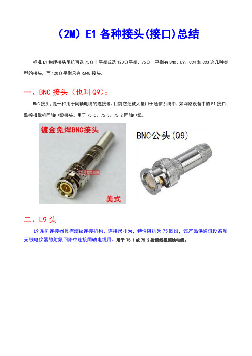
标准E1物理接头阻抗可选75Ω非平衡或选120Ω平衡,75Ω非平衡有BNC、L9、CC4和CC3这几种类型的接头,而120Ω平衡只有RJ48接头。
一、BNC接头(也叫Q9):
BNC接头,是一种用于同轴电缆的连接器。
目前它还被大量用于通信系统中,如网络设备中的E1接口、监控摄像机同轴电缆接头。
用于75-5、75-3、75-2同轴电缆。
二、L9头
L9系列连接器具有螺纹连接机构,连接尺寸为,特性阻抗为75欧姆,该产品供通讯设备和无线电仪器的射频回路中连接同轴电缆用。
用于75-1或75-2射频线视频线电缆。
三、CC4接头
CC4-J接头连接器具有卡锁连接机构,体积小,连接可靠。
CC4射频同轴连接器,可接75-2 2M电缆。
四、CC3接头
CC3-K系列产品是一种小型推入式连接器,有自锁和不自锁两种,其跨挡的中心距也有和12mm两种规格,供低功率用。
特性阻抗:75Ω。
常用于2M(E1)电缆。
五、RJ48接头
RJ48接头是在120欧姆连接时专用的物理接头。
标准的RJ48公头相比RJ45公头只是在1针脚旁边多一块小凸起,这个凸起的作用是防止RJ48公头插入RJ45母头中。
而实际使用中一般直接使用RJ45头来做RJ48网线。
RJ48与RJ45的最大不同是针脚定义,RJ48使用1、2接收,4、5发送,百兆RJ45使用1、2发送,3、6接收。
瑞萨RL78单片机和开发工具(培训教程)[RL78 Tool introduce]
![瑞萨RL78单片机和开发工具(培训教程)[RL78 Tool introduce]](https://img.taocdn.com/s3/m/83c203c26137ee06eff918d4.png)
© 2011 Renesas Electronics Corporation. All rights reserved.
5
© 2011 Renesas Electronics Corporation. All rights reserved.
The basic operation of E1
User program execution Reset Tracing Break Performance measurement
E1
In-line programming by OCD OCD with programming function
E1
OS
Itron Compliance
Debugging by High Function Emulator In-circuit Emulator
IECUBE
REBJ-AN-MC-10001
RL78 Family Development Tool Lineup Useful tools at every development stage
Coding
Debugging
Debugging on PC
Programming
Programming by Renesas Ele.
RL7 8 / G 1 3
CubeSuite
Programmed
CPU Simulator Coding/ Building/ Device Driver IDE
In Renesas Electronics’s Factory
CubeSuite
Debugging by OCD On-Chip-Debugger with Programming function
瑞萨单片机串口烧写程序具体引脚连接方法

瑞萨单片机串口烧写程序具体引脚连接方法
瑞萨单片机是一种广泛应用于嵌入式系统的芯片,其可通过串口进行程序烧写。
为了实现这一功能,我们需要进行一些硬件搭建和操作流程。
本文将详细介绍瑞萨单片机串口烧写程序的具体引脚连接方法。
一、瑞萨单片机串口烧写程序的硬件搭建
1.开发平台:Windows XP操作系统,瑞萨开发环境HEW,瑞萨烧写工具FDT。
2.单片机型号:L357C。
3.硬件原理:根据瑞萨L357C单片机Datasheet手册,使用UART0作为串行编程器的通信口。
二、瑞萨单片机串口烧写程序的操作流程
1.使用FDT直接烧录mot文件。
2.配置FDT软件,选择正确的串口号和波特率。
三、具体引脚连接方法
1.将单片机的RXD(接收数据引脚)与电脑串口的发送数据引脚(通常为RXD)相连。
2.将单片机的TXD(发送数据引脚)与电脑串口的接收数据引脚(通常为TXD)相连。
3.将单片机的VCC(电源正极)与电脑串口的电源正极相连。
4.将单片机的GND(电源负极)与电脑串口的电源负极相连。
5.为了保证电平匹配,可在单片机与电脑串口之间添加一个RS232转TTL
的电平转换模块。
通过以上硬件搭建和操作流程,即可实现瑞萨单片机串口烧写程序。
在实际操作过程中,请确保正确连接所有引脚,以避免损坏设备。
在烧写程序时,注意观察串口通信状态,确保程序成功烧入单片机。
总之,瑞萨单片机串口烧写程序的具体引脚连接方法主要包括:正确连接单片机的接收和发送数据引脚、电源正负极以及添加电平转换模块。
协议转换器e1接口

协议转换器e1接口协议转换器e1接口协议甲方(以下简称“甲方”):地址:联系人:电话:传真:营业执照号码:开户银行:账号:乙方(以下简称“乙方”):地址:联系人:电话:传真:营业执照号码:开户银行:账号:双方在平等、自愿的基础上,经协商达成如下协议:一、定义1.1 “协议转换器”是指甲方提供给乙方的设备,用于将来自E1 接口的信号转换为其他格式的信号。
1.2 “E1 接口”是指传输数字信号的一种标准接口。
1.3 本协议中所提到的“法律”是指中国的相关法律、法规等。
二、甲方的权利和义务2.1 甲方必须向乙方提供协议转换器,并保证其符合国家标准、行业标准及申报的技术规格。
2.2 甲方应保证协议转换器的性能、功能、安全、可靠性等,并负责设备的安装、调试、维护、修理等工作。
2.3 甲方应保证协议转换器的技术规格、产品说明书、操作手册等文件的真实性、准确性、完整性。
2.4 甲方应当及时处理乙方提出的质量问题和随时提供技术支持。
2.5 甲方应保证协议转换器的质保期限为一年,若设备出现质量问题,甲方应在24小时内处理,保证设备的正常使用。
2.6 甲方应当按照本协议约定的价格,向乙方出售协议转换器。
2.7 甲方应负责向乙方提供技术培训和资料,使乙方能够掌握协议转换器的使用方法。
2.8 甲方应按照法律法规要求进行备案登记。
2.9 甲方应当遵守本协议及相关法律法规的规定,履行本协议约定的义务。
三、乙方的权利和义务3.1 乙方应当按照本协议的约定支付购买协议转换器的款项。
3.2 乙方应按照操作手册的规定正确使用协议转换器,并保证设备处于正常工作状态。
3.3 乙方应检查协议转换器的完好性、签收协议转换器,并在签收时确认设备的数量、质量、型号等。
3.4 乙方应对协议转换器的损坏、误操作等问题负责。
3.5 乙方应与甲方及时沟通,并提供必要的技术资料以便甲方能提供及时的技术支持。
3.6 乙方应按照本协议约定的期限支付货款,如有逾期,需按照实际逾期时长,按照逾期利率支付利息。
服务端 一级接口定义-概述说明以及解释

服务端一级接口定义-概述说明以及解释1.引言1.1 概述服务端一级接口定义是指在服务端开发中对接口进行规范化、统一化的定义,以确保接口的稳定性、可维护性和可扩展性。
通过定义服务端一级接口,可以让不同的团队成员在开发过程中遵循同一标准,提高团队合作效率和代码质量。
在现代的软件开发中,服务端一级接口定义起着至关重要的作用,它不仅可以帮助开发人员快速定位问题和解决bug,还可以让接口文档更加清晰易懂,降低沟通成本。
因此,深入理解和规范定义服务端一级接口是每个服务端开发人员都应该掌握的重要技能。
1.2 文章结构文章结构部分主要介绍了整篇文章的组织框架和每个部分的内容概要。
通过文章结构的设定,读者可以清晰地了解到本文的篇章结构以及每个部分的内容和重点。
具体来说,文章结构部分会包括以下内容:- 每个部分的标题:例如引言、正文和结论等- 每个部分的子标题:例如概述、文章结构、目的等- 每个部分的内容概要:用简洁、明确的语言对每个部分的主要内容进行介绍,让读者在阅读整篇文章之前对文章的主要内容有一个整体的把握。
通过文章结构部分的设置,读者可以在阅读文章之前就对整个文章的内容和结构有一个整体的了解,有助于读者更好地理解文章的主旨和重点,提高阅读的效果和效率。
1.3 目的在服务端开发中,定义清晰的一级接口对于整个系统的设计和实现非常重要。
我们需要明确地规定每个接口的功能、输入、输出以及调用方式,以确保系统的稳定性和可维护性。
通过定义一级接口,可以帮助团队成员更好地理解和沟通系统的设计,减少开发过程中的误解和冲突。
同时,良好的一级接口定义也能够提高系统的可扩展性和灵活性,使系统更易于扩展新功能和适应变化。
因此,本文旨在说明服务端一级接口定义的重要性,并提供指导原则和实践经验,帮助开发团队更好地设计和实现服务端接口。
2.正文2.1 什么是服务端一级接口定义服务端一级接口定义是指在服务端程序中定义的最顶层的接口,也称为API(应用程序接口)。
《E1接口电路原理》PPT课件

计算方法如下:因变压器两侧功率相同得出 如下式子:
PL=IL*UL
PR=IR*UR
UL=2UR(变压器匝数比1:2)
UL=RL*IL
UR=RR*IR
PL=PR
PL变压器左侧功率;PR变压器右侧功率;IL 变压器左侧电流;IR变压器右侧电流;UR变压器 右侧电压;UL变压器左侧电压;RR变压器左侧的 部分在变压器右侧对应的等效阻值;RL变压器左 侧阻值。
6DB衰减问题
国标要求E1接口必须能通过6DB衰减不影响业 务的测试,这一性能主要是由接口电路接收芯片 的自身性能决定的。如果衰减后电平值过低,低 于接收器的接收极限值,接受器就不输出,导致F PGA收不到E1信号。如果遇到这个问题,可以通过 调节接口电路的部分电阻值来调节接受器的基准 判决电平。在例图1中,可以调节R45和R54,通过 它们使得A、B点电平值降低,从而使-INA、-INB、 -INC、-IND收电平值降低。MC3486输出信号是+IN 与-IN比较得来的,降低-IN相当于使极限值增大。
图2、发送端P端各点波形
三、发送端说明
发送端主要有两部分组成:驱动器74LS240, 变压器PT28-2003H。
74LS240的主要作用是驱动FPGA的E1输出信 号。
变压器的主要作用是电平调整和变换。
其电平变化过程如下图:
变压器输入端以第二个波形(N端信号)为基准信号同第 一个波形(P端信号)比较,输出结果如第三个波形。
放映结束,谢谢大家!
感谢下 载
E1接口电路原理
作者 开发部:王大伟
一、概述
本次讲座的主要内容是E1接口电路。 E1接口 电路是E1插口与E1信号处理芯片之间的部分,这 一部分电路主要作用有如下几点:
双V.35接口E1转换器应用说明

GVE1-2 2端口E1复用器用户手册目录第一章概述第二章前言第三章技术指标第四章安装和使用2.1电源和环境要求2.2前后面板2.3串行接口信号线2.4内部开关设置第五章技术支持第一章概述1.1前言GVE1-2是用ASIC电路设计最新研制成功的E1/G.703到V35/V24的2端口、复用器。
GVE1-2数据端口的速率最高可设置成N×64Kbps(N=1-31),但2个端口的速率相加必须≤1984Kbps,它既可以是V.35也可以是V.24;V.24不仅支持同步64K/128K,也能自适应≤38 .4bpsK的异步接口。
每个数据端口的起止时隙(TimeSlot)由硬件开关设定,无需任何软件输入。
GVE1-2线路采用HDB3编码, 数据为透明传输,线路阻抗120Ω(RJ45)和75Ω(BNC)可选,在面板上能方便地执行本端模拟环路和远端G.703数字环路,以实现端对端的完整性测试,方便用户进行线路测试和故障诊断。
GVE1-2 前面板有丰富的指示灯,显示设备的工作状态及告警信号。
在成对使用时, 数据端口之间可交叉联接,不必一一对应。
GVE1-2满足ITU的G.703、G.704和G.706的要求。
GVE1-2符合国家GB6879-86《2048kbit/s 30路脉码调制复用设备技术要求》的标准,支持多种子速率信号的复接。
典型应用如下:703接2 K1.2技术指标1.2.1 线路接口(E1)子速率复接:符合国家标准GB6879-86《2048kbit/s 30路脉码调制复用设备技术要求》的标准,支持多种子速率信号的复接。
编码:HDB3数据传输速率:N×64Kbps(N=1--31);线路接口:阻抗75Ω,物理接口BNC;阻抗120Ω,物理接口RJ45;传输特性:符合G.703,G.704,G.706,支持CRC4;时钟:线路时钟(LINE)。
测试方法:本地模拟环路,远端数字环路;DCE接口: V.35或V.24/RS232C;电源:交流220V±10%,50Hz;或直流-48V±10%功耗:5W;体积:245mm×215mm×55mm;1.2.2 数据端口端口:2个V.24/RS232或V.35 DCE物理接口:同步V.24/V.35异步V24/RS232 自适应≤38 .4Kbps;时钟:G.703线路LINE从时钟第二章安装和使用本章介绍GVE1-2的前后面板、指示灯、开关、接口以及连接电缆。
loopback及E1线缆定义

一.华为路由器ppp封装,线路向本端打环时,可看到loopback set ,但端口up,协议down hdlc封装,线路向本端打环时,可看到loopback set ,端口up,协议upE1PPP封装时,只要接外线,端口就是UP,协议DOWNCE1HDLC封装时,线路上有设备端口和协议才有可能UP二..线缆定义说明RJ45头连接华为模块时DDF架6 5 4 3 2 1RJ45头连接CISCO模块时DDF架DB15头连接华为模块时DDF架收9 2 10 8 15 7DB15头连接CISCO模块时注:石家庄移动DDF架多为左发右收,其他地市可能有变化发收DDF架收6 5 4 3 2 1收发发收收发1.华为详表:2.Cisco详表∙VWIC-1MFT-G703∙VWIC-2MFT-G703E1-G.703/G.704 Port Adapter and Cable PinoutsTable 4 shows the signal pinouts for each type of E1-G.703/G.704 interface cable. All cables use a DB-15 connector at the FSIP end.Table 4: E1-G.703/G.704 Adapter Cable Connector Pinouts1Any pins not described in Table 4 are not connected. 2Tx = transmit. Rx = receive.Table 3: E1-G.703/G.704 Maximum Cable Lengths。
E1口介绍

4.2.1 局域网的基本硬件组成
• 在整个网络中,服务器的工作量通常是普 通工作站的几倍甚至几十倍。在一般的场合, 如普通的办公、教学等场合可以采用配臵较高 的普通电脑来作为服务器使用,选择速度比较 快的处理器,容量比较大的内存和硬盘,主板 等其他配件应选购品牌产品,保证质量稳定、 可靠,声卡、显卡等设备则要求不是很高;如 果对网络要求比较高,需要处理的事务比较复 杂,就应采用专用的服务器产品,相比而言专 业服务器具有更好的安全性和可靠性、更高的 I/O吞吐量,因此其价格也比较昂贵。在服务器 上安装的操作系统典型地如UNIX、Linux、 Windows2000/XP/2003、Novell Netware等。
• (2)用户可以通过各种Web服务器查询、 发布信息,收发电子邮件,在各个部门之 间传达各种指示、通知等,方便各个部门 之间的信息沟通; • (3)利用局域网络实现和其他网络的互联, 例如连接到Internet上,享受网上冲浪的 乐趣,丰富用户的业余生活。
4.2 局域网的组成
• 在讨论局域网的组成时,可以按照单机系 统的组成方式来进行分析。单个的计算机系统 可以分为硬件系统和软件系统两大组成部分, 计算机的各个部件通过一定的线路相连,在操 作系统的控制下有机、协调地工作,完成用户 的各项任务。在局域网中,同样需要将一些硬 件设备通过线路互相连接,也同样需要软件的 控制才能实现相互之间的通信。那么,在一般 的局域网中,这两大部分应该包括哪些基本内 容呢?下面来进行说明。
4.2.1 局域网的基本硬件组成
• 需要指出的是,对服务器和工作站的区 分,不是按照计算机所选用的软硬件配臵情 况来划分的,而主要是从应用的角度,看计 算机是否向网络提供服务来进行区分。在某 台计算机上安装一个服务器软件为其他用户 提供网络服务时,它就成为了提供某个网络 服务的服务器;同时它也可能向其他的服务 器申请网络服务,这时该计算机的身份又是 客户机。另外,在一种称之为“对等网”的 网络中,各台计算机的地位都是平等的,每 台机器既可以作为服务的提供方,也可以接 受来自其他计算机所提供的服务。在对等网 里就没有服务器和工作站的区分。
瑞萨仿真器e1连接
R20UT0398CJ0200
User's Manual E1 仿真器 R0E000010KCE00 E20 仿真器 R0E000200KCT00
用户手册
本资料所记载的内容,均为本资料发行时的信息,瑞萨电子对于本资料所记载的产品或者 规格可能会作改动,恕不另行通知。 请通过瑞萨电子的主页确认发布的最新信息。
表11e1包装内容一览表表12e20包装内容一览表名称说明数量e1仿真器r0e000010kce00usb接口电缆插头minib插头15m高速规格产品用户接口电缆14芯扁平电缆02m安装媒体综合开发环境仿真调试程序e1e20仿真器用户手册名称说明数量e20仿真器r0e000200kct00usb接口电缆插头minib插头15m高速规格产品用户接口电缆38芯软性电缆02m选项电路板38引脚14引脚转换适配器r0e000200cka00安装媒体综合开发环境仿真调试程序e1e20仿真器用户手册请保管好包装箱和缓冲材料以便在故障修理及其他运输时使用
Rev.2.00பைடு நூலகம்
2011.02
Notice
Notice
1. All information included in this document is current as of the date this document is issued. Such information, however, is subject to change without any prior notice. Before purchasing or using any Renesas Electronics products listed herein, please confirm the latest product information with a Re
E1接口引脚定义-20021122-B

资料名称
拟制:肖海军日期:2002.11.22 审核:日期:
审核:日期:
批准:日期:
华为技术有限公司
版权所有侵权必究
修订记录
目录(TOC Heading)
155A 2M接口引脚定义 (1)
关键词:Optix 155A、E1
摘要:无
缩略语清单:无
参考资料清单:
120欧输出口引脚定义-20020630-B
TELLIN 移动智能网原理与系统技术手册(页眉)错误!未找到引用源。
155A 2M接口引脚定义155A 2M接口引脚定义
SBS155A(H)2M通过DB37插头引出,每个DB37插头引出8个2M输入、
输出口共32根引线,即每个E1需要用四根引线,如下图所示:
上图中的管脚标号定义采用如下原则:
第1、2个字母表示该引脚是输入还是输出引脚:RJ为输入,TJ为输出,即
RJ为收,TJ为发。
第3、4位的数字表示该引脚的2M极性和位置:第3位为1时表示TIP端,
为2时表示为RING端,第4位取1-8分别表示对应于第1到第8个2M,1
-8个2M顺序定义如下:从机盒后面面对拉手条,DB37头上从右到左依此
对应1-8,从网管上看1-4对应于SP1右的1-4,5-8对应于SP1左的
1-4。
上图中的GND在75欧时使用,在120欧时不作处理。
这点遵循的是ITU-T
G.703:E1收RING必须接地,E1发RING可以接地。
DB37的管脚序号在器件上有标注。
瑞萨发布微控制器的开发工具E8a仿真器-新品速递

瑞萨发布微控制器的开发工具E8a仿真器-新品速递--体积比目前的瑞萨产品减少约40%,具备片上闪存等编程功能适用性,可扩展应用于所有瑞萨微控制器系列--瑞萨科技公司(RenesasTechnologyCorp.)宣布,推出一种用于瑞萨微控制器开发工具的名为“E8a仿真器”的超小型、低价格、环保型片上调试仿真器*1。
样品供货将于2022年2月从日本开始。
这种仿真器是用于M16C 系列等瑞萨微控制器和其他产品的E8仿真器低价格开发工具的后续产品。
与E8仿真器相比,E8a仿真器的体积减少了大约40%,同时继承了其仿真功能和易用性。
此外,对片上闪存和其他存储器的编程功能的微控制器适用范围也进行了大幅度的扩展。
E8a仿真器可提供以下特性。
(1)将片上闪存等编程功能的适用性扩展到所有瑞萨微控制器系列E8a仿真器的功能与瑞萨目前的E8仿真器兼容。
此外,片上闪存和其他存储器的编程功能已覆盖以前并不支持的瑞萨产品,包括SuperH系列*2和H8S系列微控制器。
瑞萨提供的闪存开发工具包软件一起使用,E8a仿真器可以作为一个编程器用于带有闪存等片上程序存储器的所有微控制器系列。
这将有助于用户在量产过程中以低成本建造大规模微控制器编程线。
(2)超紧凑的尺寸和使用环保型材料的新设计新设计采用了瑞萨科技商标的红色和一个附加的色带,超紧凑型封装尺寸为92mm×42mm×15mm;与E8仿真器相比,占板面积大约减少了30%,体积减少了大约60%。
为了体现环保,其外壳采用了一种基于蔬菜的聚交酯生物降解塑料。
这种超小型尺寸在使用大量仿真器时也不会占用太大的存储空间。
(3)扩展的片上存储器编程工作电压范围通过降低下限电压,其支持的微控制器编程工作电压范围可从3-5V扩展到1.8-5V,有助于E8a仿真器用于未来的可能使用较低编程电压的微控制器的闪存和其他存储器。
此外,集成的时钟振荡器可以利用与微机一致的工作频率实现异步通信。
- 1、下载文档前请自行甄别文档内容的完整性,平台不提供额外的编辑、内容补充、找答案等附加服务。
- 2、"仅部分预览"的文档,不可在线预览部分如存在完整性等问题,可反馈申请退款(可完整预览的文档不适用该条件!)。
- 3、如文档侵犯您的权益,请联系客服反馈,我们会尽快为您处理(人工客服工作时间:9:00-18:30)。
Notes 1. The circuit enclosed by a dashed line is not required when only flash programming is performed. 2. Pull-up resistor is not required if the reset circuit on the target system contains no buffers and the reset signal is only generated via resistors or capacitors. 3. The drive power supply of TOOL0 is different depending on devices. Defer to user’s manual of device.
© 2010 Renesas Electronics Corporation. All rights reserved.
ルネサス エレクトロニクス株式会社
© 2010 Renesas Electronics Corporation. All rights reserved.
Note. As seen from E1.
© 2010 Renesas Electronics Corporation. All rights reserved.
Circuit connection example
Caution The constants described in the circuit connection example are reference values. If you perform flash programming aiming at mass production, thoroughly evaluate whether the specifications of the target device are satisfied. Target device Target connector VDD VDD Note 3 VDD 8. VDD The drive power supply of TOOL0 EVDD 9. EMVDD 2. GND
Nov 21, 2010 Rev. 1.00
© 2010 Renesas Electronics Corporation. All rights reserved.
ZUD-F35-10-0114
Pin assignment
This section describes the interface signals used between E1 and the target sysve power supply of TOOL0 1kΩ
12. GND 14. GND
5. TOOL0 10. _RESET 13. _RESET 6. _TRESET Note 1 10kΩ VDD Note 2 1kΩ
TOOL0 _RESET
Reset connector RESET signal
No. 1 2 3 4 5 6 7 8 9 10 11 12 13 14
Pin name R.F.U GND R.F.U R.F.U TOOL0 _TRESET VDD EMVDD _RESET R.F.U GND _RESET GND
IN/OUT Note IN/OUT IN OUT OUT -
Pin assignment of target connector to be mounted on target system (TOP VIEW)
CUSTOMER NOTIFICATION
E1 circuit connection example for RL78
MCU Tool Product Marketing Development MCU Software Division MCU Business Unit Renesas Electronics Corporation
