东风本田思域车身维修维修手册(2007本田思域混合动力车身修理手册 5M9)
2007 Honda Civic Si 发动机说明书
Drive-by-WireT Throttle System
CARB Emissions Rating Direct Ignition System with Immobilizer 100,000-Miles-or-More Tune-Up Interval†
TRANSMISSION Close-Ratio 6-Speed Manual Transmission Helical Limited-Slip Differential
COMFORT & CONVENIENCE Air Conditioning with Air-Filtration System
Honda Satellite-Linked Navigation SystemT 2
with Voice Recognition Power Windows with Auto-Up/Down Driver’s Window Power Door Locks with Auto-Lock Feature Cruise Control Perforated Leather-Wrapped 3-Spoke Steering Wheel Aluminum Shift Knob with Leather Textured Aluminum Pedals
SAFETY 3-Point Seat Belts at All Seating Positions Front 3-Point Seat Belts with Automatic Tensioning System Driver’s and Front Passenger’s Seat Belt Reminder Adjustable Front Seat Belt Anchors Dual-Stage, Dual-Threshold Front Airbags (SRS) Front Side Airbags with Passenger-Side Occupant Position Detection System (OPDS) Side Curtain Airbags Driver’s and Front Passenger’s Active Head Restrinder Aluminum-Alloy
2007款东风本田思域车身及附件维修手册
车内装饰件
组件位置索引..................................... 20-69 装饰件的拆卸/安装—车门部位........... 20-70 *装饰件的拆卸/安装—支柱部位 —无侧面安全气帘................................ 20-73 *装饰件的拆卸/安装—支柱部位 —有侧面安全气帘 ............................... 20-76 *装饰件的拆卸/安装—后行李架部位 ..... 20-85 装饰件的拆卸/安装—行李箱部位......... 20-87 装饰件的拆卸/安装—行李箱盖 ............ 20-89 拉手的拆卸/安装.................................. 20-90 *车顶内衬的拆卸/安装........................... 20-92 *地毯的更换.......................................... 20-97
翼子板
前内翼子板的更换.............................. 20-176 挡泥板的更换 ..................................... 20-177 前翼子板罩的更换.............................. 20-178 燃油管保护件的更换 .......................... 20-179 后翼子板罩的更换.............................. 20-179 后送风口的更换 ................................. 20-180
车身及附件维修手册
专用工具............................................ 20-2
款东风本田思域自动变速箱维修手册(5)
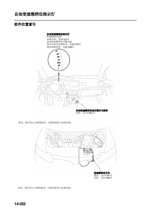
自动变速箱档位指示灯组件位置索引自动变速箱档位指示灯F-CAN通讯电路故障处理,见22-222页仪表控制模块自诊断功能指示灯驱动电路检查,见22-208页通讯线路检查,见22-209页自动变速箱档位指示器灯光线束更换,见14-258页说明:图中所示左侧驾驶型;右侧驾驶型与此相对称。
变速箱档位开关测试,见14-254页更换,见14-256页说明:图中所示左侧驾驶型;右侧驾驶型与此相对称。
14-252.;14-253电路图CANH仪表控制模块白粉红 棕 黑 白/红 黑/蓝红/黑 蓝黄/红 蓝/白 红红/黑黑黑 棕/黄 棕/黄黑黑 F-CAN 收发器仪表板灯 亮度控制 电路自动变 速箱档 位指示 灯驱动 器电路自动变速 箱档位指 示灯盘灯棕灰黑/黄蓝/黄 黄 棕 红 黄/绿 红/黑 PCM 线束插头端子位置凹头插头端子侧C(44芯)B(44芯) A(44芯)黑蓝/白橙蓝/黑白/绿 白 白 红CANL动力系统控制模块(PCM)发动机盖下保险/继电器盒 点火开关仪表板下保险/继电器盒红 红灰 多路控制器(MICU)多路控制器(MICU)BAT蓄电池CAN 控制器变速箱档位开关起动机切 断继电器自动变速箱档位指示灯14-254变速箱档位开关的测试1. 拆下空气滤清器壳和进气导管(见11-308页)。
2. 断开变速箱档位开关线束插头(A)。
3. 检查线束插头处端子之间的导通性。
对于每个开关位置来说,下表中的各端子之间应导通。
变速箱档位开关线束插头4. 如果测试结果正常,则表示完成变速箱档位开关的测试。
如果任何端子之间不导通,则进行第5步。
5. 施加驻车制动,并阻止两后轮。
抬起车辆前部,并确保将其牢固支撑。
或举升车辆。
6. 拆下变速箱档位开关罩。
凸头插头端子侧插头端子/信号位 置.;14-2557. 断开变速箱档位开关插头。
8. 检查开关插头处端子之间的导通性。
对于每个开关位置来说,下表中的各端子之间应导通。
变速箱档位开关线束插头9. 如果变速箱档位开关导通性检查正常,则更换出现故障的变速箱档位开关线束。
HONDA 汽车综合维修指南说明书
CUSTOMER INFORMATION: The information in this bulletin is intended for use only by skilled technicians who have the proper tools,equipment, and training to correctly and safely maintain your vehicle. These procedures should not be attempted by “do-it-yourselfers,” and you should not assume this bulletin applies to your vehicle, or that your vehicle has the condition described. To determine whether this information applies, contact an authorized Honda automobile dealer.Body Repair NewsDecember, 201707817 Version 32017–18 Clarity Series New Model Body Repair InformationThis publication contains a summary of new body and vehicle technologies that may affect collision and other body repairs. Always refer to the appropriate body repair manual and service information for complete repair information. A subscription may be purchased at: APPLIES TO Year Model2017 Clarity Fuel Cell 2017 Clarity Electric2018Clarity Plug-In HybridTABLE OF CONTENTS New Model Body Technology Page 2 Body Repair InformationPage 6 Welding Precautions and Information Page 8 Before Starting Collision Repairs Page 10 During Collision RepairsPage 12 After Collision RepairsPage 12 Authorized Honda Clarity DealersPage 13IDENTIFYING THE TYPE OF CLARITY MODELTo determine the type of Honda Clarity you are working on, refer to characters 4 thru 6 of the VIN.JHM ZC4*****000001ZC4 Clarity Fuel Cell ZC5 Clarity Plug-In Hybrid ZC6 Clarity ElectricOVERVIEW OF BODY FEATURES• The same basic body platform supports three electric-powered model variations.• Body construction using 52% lightweight materials, including aluminum and ultra-high-strength steel (UHSS - 980 MPa and higher).• World’s first Glass Fiber Reinforced Polymer/Plastic (GFRP) rear bumper beam.• Bolt-on resin composite front bulkhead assembly.• All models are equipped with Honda Sensing®, which includes these advanced safety and driver-assistive technologies: Adaptive Cruise Control with Low Speed Follow, Lane Keeping Assist System, Road Departure Mitigation, and Collision Mitigation Braking System™ with pedestrian sensing capability.WARNING• Compressed hydrogen gas is flammable and highly explosive. You could be killed or seriously injured if leaking hydrogen gas is ignited.• Keep heat, sparks, and flames away. In addition, keep electronic devices that can emit static discharge away.• Hydrogen burns very quickly and radiates less heat than gasoline or other fuels; its flames are invisible.• Always, have a fire extinguisher (dry powder type or carbon dioxide gas type) at the work location at all times.• Only properly trained technicians should inspect and repair the Clarity’s high-voltage and/or hydrogensupply systems.• The California Fire Code has specific requirements for welding and open flame repairs on hydrogenfueled vehicles like the Clarity Fuel Cell. Do not conduct welding or open flame repairs on the ClarityFuel Cell without first determining whether your facility is properly equipped and the vehicle is properlyprepared.NEW MODEL BODY TECHNOLOGYBody Construction and High-Strength Steel Content• Steel parts are color coded based on their tensile strength in megapascals (MPa).• High-strength steel (HSS) is defined as any steel with a tensile strength of 340 MPa or higher.• Ultra-high-strength steel (UHSS) is defined as any steel with a tensile strength of 980 MPa or higher.• Steel repair and welding procedures vary, depending on the tensile strength of the parts involved.NOTE: The following illustrations are for general reference only. Some body parts are made from multiple layers of different tensile strength steels. Refer to the Body Construction section of the body repair manual for specific steel tensile strengths.1500 MPa 980MPa780MPa270MPa440MPa1.500 MPa (Hot Stamp) Steel Locations1,500 MPa steel is stronger than ordinary steel, so it can help protect vehicle occupants while reducing overall vehicle weight to improve fuel efficiency.The numbered parts in the illustration below are made of 1,500 MPa steel.1 Front Inner Upper Panel 5 Side Sill Reinforcement2 Front Pillar Upper Stiffener 6 Center Pillar Upper Stiffener3 Front Side Frame Extension 7 Roof Side Stiffener4 Front Pillar Lower Stiffener 8 Floor Crossmember StiffenerNote: 1,500 MPa Stiffeners are located inside the front floor frame, front floor crossmember, and front floor rear crossmember.Resin Composite (Plastic) Front Bulkhead AssemblyThe Clarity has a front bulkhead assembly made from resin composite material.• The bulkhead design improves engine compartment access during factory assembly and service.• The front bulkhead is attached with multiple bolts and is sold and replaced only as a complete assembly.• The cooling fans, radiator, A/C condenser, hood lock, outside air temperature sensor, and related piping/components are attached to the front bulkhead using molded-in M6/M8 threaded inserts.• Over torqueing or using power tools may break these inserts loose, requiring front bulkhead replacement.• A damaged bulkhead must be replaced, not repaired.• For more information, refer to “Front Bulkhead Replacement” in the body repair manual.Aluminum Parts and ReparabilityThe following parts are made from aluminum alloy:Front Bumper Beam Rear Shelf PanelsHood Panel Trunk LidFront Fenders Front and Rear Subframe (Not shown)Front and Rear DoorsAluminumLaser-Brazed Roof AttachmentThe factory-installed roof panel is attached using a laser-brazed joint to the outer side panels.•Laser-brazed joints cannot be duplicated during roof panel replacement.•The original roof panel must be cut off near the laser-brazed joint and the remaining flange removed separately. •The service roof panel is attached using service replacement bolted clamp-type brackets (five per side) and panel bonding adhesive.•The roof panel, service brackets, and bolts must be ordered separately. Refer to the online parts catalog.•Refer to “Roof Panel Replacement” in the body repair manual.BODY REPAIR INFORMATIONNOTE: The following content is intended only to highlight new/special concerns. No body repairs should be attempted without first referencing the applicable body repair manual.Use of Heat During Body Straightening and RepairWhen you are doing body straightening and repair procedures, follow these guidelines:• Do not apply heat to any body part during straightening. This may compromise the internal structure and strength of high-strength steel parts.• Any part that has heat applied to it during straightening must be replaced with new parts.• Ignoring these instructions may significantly reduce occupant protection in any subsequent collision.Sectioning (Cut and Joint) GuidelinesVarious high-strength and ultra-high-strength steel materials with different sheet thicknesses and strengths are applied in many places that vary with body design in order to increase collision safety performance, body stiffness, and weight reduction. Stiffening members are also applied inside some steel parts (patches, reinforcements, stiffeners, etc.)Follow these guidelines to avoid an unsafe repair:• Outer body and floor panels may be sectioned as necessary. Specific sectioning procedures are not provided in the body repair manual.• Depending on the type of vehicle damage, steel parts with a tensile strength of 780 MPa or less may be sectioned, as long as all three of the following conditions are met:- Sectioning must be done in a single-layer area of the part.- Multi-layer internal steel reinforcements and stiffeners must not be cut.- Sectioning must be done in load bearing areas such as engine, transmission, or suspension mounting points.• If any of the above sectioning conditions cannot be met, replace those body structural components (stiffeners, reinforcements, and other multi-layered steel parts) as assemblies that match the replacement parts configuration. • Approved welding methods are shown in the table at below. • Refer to the body repair manual for complete procedures.• MAG plug welding is now allowed on 1,500 MPa (hot stamp) steel parts in select locations only as specified in the body repair manual.Welding Method for Steel PartsΟ= Approved X = Not Approved Ο* = Approved only if specified in BRMSteep Part TensileStrength Welding MethodSpot WeldingMAG WeldPlug ButtSectioning Area Examples<590 ΟΟΟ590 ΟΟΟ780 ΟΟΟ980 ΟΟX1,500 ΟΟ*X• Welding instructions must be followed exactly as specified to ensure adequate weld strength.WELDING PRECAUTIONS AND INFORMATIONREPAIRING 1,500 MPa STEEL PARTSObserve these precautions when repairing 1,500 MPa steel parts:• Never attempt to straighten damaged 1,500 MPa steel parts; they may crack.• 1,500 MPa steel parts must be replaced at factory seams using only approved repair methods. Do not section these parts.• MIG-brazed joints should be used only in locations not accessible by a spot welder.• To ensure adequate weld tensile strength, always manually set the spot welder to the specifications provided in the body repair manual.• Unapproved MAG welding procedures on 1,500 MPa steel may generate heat levels that will significantly reduce the strength and structural integrity of 1,500 MPa steel parts.• The photo below shows a tensile strength test results of an improperly MAG welded 1,500 MPa steel part. The 1,500 MPa side fractured first because excessive welding heat reduced its strength.• For more details, refer to “Basic Welding Information” the Body section of the service information.Parts made of Ultra-High-Strength Steel (UHSS/1,500MPa/USIBOR) must be installed as a complete part. No sectioning is allowed. Ultra-High-Strength Steel requires special welding equipment, procedures, and settings. See the welding section of the body repair manual. Failure to use the proper equipment or follow the proper procedures can result in an unsafe repair.MIG Brazing Guidelines for 1,500 MPa Steel PartsNOTE: Refer to the body repair manual for complete procedures.• MIG-brazed joint locations are specified in the body repair manual.• A single- or double-hole MIG braze may be specified, depending on the tensile strength of the parts being joined. • The size and number of holes are critical to achieving adequate joint strength.• A MIG welder with pulse control must be used. Refer to the equipment manufacturer’s instructions for welder voltage and current setup.• The photos below show the difference in results between pulsed and non-pulsed MIG brazing.MAG Welding Specifications for 590–980 MPa High-Strength Steel PartsNOTE: In this publication and the body repair manual, gas metal arc welding (GMAW) is referred to by its subtypes depending on requirements as follows:• MIG Welding/Brazing = This refers to metal inert gas welding or brazing where 100% argon (Ar) shielding gas is used. Argon is inert and does not react with the molten weld pool or brazing operation.• MAG Welding = This refers to metal active gas welding where the shielding gas being used contains a mixture of 80% argon (Ar) and 20% carbon dioxide (CO 2). It is considered active because the CO 2 undergoes a limited reaction with the molten weld pool.• For MAG welding, 80/20 shielding gas (C20) is preferred. However, 75/25 (C25) is acceptableParts made of high-strength steel (590-980 MPa) must often be installed as a complete part. Section only according to published repair information and guidelines. This high-strength steel requires special weldingequipment, procedures, and settings. See the Welding section of the body repair manual. Failure to use the proper equipment or follow the proper procedures can result in an unsafe repair.The body repair manual specifies the weld types and locations for each body panel as follows:• The welding wire used must have a tensile strength equal to or greater than the lowest tensile strength of the parts being welded. The conversion chart below shows the relationship of steel tensile strength (MPa) to the minimum welding wire tensile strength (in kilopound per square inch [ksi]).Steel Tensile (MPa) Wire Tensile (ksi)590 ≥86 780 ≥113 980 ≥142(1,000 psi = 1 ksi)• Typical ER70S-6 MIG wire has a minimum tensile strength of 70 ksi (483 MPa). It can be used when welding up to 440 MPa steel parts. Refer to the diagrams below:MAG Plug Welding Guidelines• MAG plug welding may be done when joining body components to 590–980 MPa steel parts.• MAG plug may also be used on 1,500 MPa steel parts only as specified in the body repair manual.• Follow the recommendations described in the body repair manual.MAG Butt Welding Guidelines• MAG butt welding may be done only on steel parts with a tensile strength of 780 MPa and lower.• Welding speed is critical to achieve the correct weld strength and minimize the heat affected zone (HAZ).• Follow the recommendations described in the body repair manual.BEFORE STARTING COLLISION REPAIRSWith any collision repairs, always refer to and follow the information outlined in the Generation Information section of the body repair manual. The following information outlines special consideration when repairing a Honda Clarity.IPU (Intelligent Power Unit) Leak Test After Airbag DeploymentApplies ToClarity Electric Clarity Plug-In HybridAn IPU leak test must be done on any Clarity Electric or Clarity Plug-In Hybrid involved in a collision severe enough to deploy the airbags. The test consist of pressurizing the IPU with shop air to check for any leaks. If the IPU does not pass leak check, it must be replaced.The Clarity Electric has a front and rear IPUs. Both of these units must be checked. If you have a vehicle with deployed airbags, take it to an authorized Honda dealer to have this test done before starting any repairs.High-Voltage System ComponentsApplies ToClarity Electric Clarity Plug-In Hybrid Clarity Fuel CellIf you are doing any repairs that require the removal of high-voltage system components, the vehicle must be taken to an authorized Honda dealer. Authorized Honda dealers have the training and equipment needed to remove and install high-voltage components.Refer to the Electrical Powertrain Component Location Index in the service information for a complete list of high-voltage system components.Hydrogen System/Fuel Cell System ComponentsApplies ToClarity Fuel CellAccording to California Fire Code, the hydrogen level in the hydrogen tanks must be less than 0.5 kg before the vehicle is brought inside the shop for repairs related to the hydrogen system. These rules do not apply for servicing/repair of non-hydrogen system components and collision repairs as long as no repairs involving welding or open flame are done and the hydrogen system components are not involved.If you are doing any repairs that involve any hydrogen system or fuel cell system related components or involve welding or open flame, the vehicle must be taken to an authorized Honda Clarity Fuel Cell dealer. For a list of authorized Honda dealers, for a list of authorized Honda dealers, refer to page 12.Refer to the Fuel Cell System Component Location Index in the service information for a complete list of hydrogen/fuel cell system components.DURING COLLISION REPAIRSWith any collision repairs, always refer to and follow the information outlined in the General Information section of the body repair manual. The following information outlines special consideration when repairing a Honda Clarity. Precautions When Using a Heated Paint BoothSystem PrecautionsSRS • Do not apply heat greater than 212°F (100°C) when drying painted surfaces anywherearound the SRS components.Fuel Cell • When drying paint in a heated paint booth, cover the air intake duct, exhaust pipe, andventilation ducts with a tape. Refer to the Fuel Cell System Component Location Indexin the service information for the location of these components.• High temperature may damage the fuel cell (FC) stack and the compressed hydrogengas (CHG) tank. When drying paint in a heated paint booth, make sure thetemperature does not exceed 149°F (65°C).Electric Powertrain • High temperature may damage the battery module. When drying paint in a heatedpaint booth, make sure the temperature does not exceed 149°F (65°C).AFTER COLLISION REPAIRSCollision Shut-off History Clear CommandWhen the battery condition monitor module receives a collision detection signal (CDS) from the SRS unit or the H2 (hydrogen) shut-off unit (Clarity Fuel Cell only), it updates the collision shut-off history and stores it in the module’s nonvolatile memory. The battery condition monitor module stops supplying power to the high-voltage circuits disrupting the control signal to be sent to the high-voltage contactor inside the battery module the next time the system is being turned on.The battery condition monitor module also stops supplying hydrogen to the FC stack by turning the FC cut relay at the same time. To resume power supply to the high-voltage circuits and hydrogen supply to the FC stack, the collision shut-off history must be cleared.Aiming Driving Support SystemsThe Honda Clarity is equipped with advanced safety driving support systems to help warn drivers and mitigate hazards. It is very important that the components making up this system are properly amied after a collision repair.Use the following table to determine what component requires aiming.Component When to AimMultipurpose Camera • Whenever the multipurpose camera unit is removed or replacedMillimeter Wave Radar • Whenever the millimeter wave radar unit is removed or replaced• After any front-end collision repairsLaneWatch™ Camera • Whenever the LaneWatch™ camera, right-side power mirror or right-front door isremoved or replaced• Whenever the right-front door is adjusted• Whenever the right-front door is repairedIf aiming is required, take the vehicle to an authorized Honda dealer.AUTHORIZED HONDA CLARITY DEALERSThe Clarity Electric and Clarity Plug-In Hybrid can be taken to any Honda dealer for service and repairs. To locate an authorized Honda dealer, contact Honda Customer Service at (800) 999-1009. Repairs to the Clarity Fuel Cell only should be undertaken by Authorized Clarity Fuel Cell dealers.For a list of authorized Honda Clarity Fuel Cell dealers, see below:Authorized Honda Clarity Fuel Cell DealersCity Dealer Name Telephone NumberCerritos, CA Norm Reeves Honda Superstore(888) 849-4466Culver City, CA Culver City Honda(424) 298-4875Irvine, CA Norm Reeves Honda Superstore Irvine(888) 721-4053Pasadena, CA Honda of Pasadena(866) 788-5832Torrance, CA Scott Robinson Honda(855) 725-2211Woodland Hills, CA Woodland Hills Honda(800) 494-1164City Dealer Name Telephone NumberColma, CA Honda of Serramonte (888) 892-5396Dublin, CA Dublin Honda (877) 412-7199Oakland, CA Honda of Oakland (800) 352-1859Palo Alto, CA Anderson Honda (650) 843-6041Roseville, CA AutoNation Honda Roseville (916) 467-8056San Jose, CA Honda of Stevens Creek (855) 357-6146END。
东风本田思域(2007款)原厂发动机电气系统维修手册

12V 蓄电池
车身(地线)
3. 如图所示连接蓄电池。确保已从电磁阀上断 开起动机导线。如果起动机小齿轮弹出,则 说明其工作正常。
4. 从M端子上断开蓄电池。如果小齿轮没有缩 回,则说明电磁阀保持线圈工作正常。
车身(地线)
6. 将起动机牢牢固定在台钳上。 7. 重新连接M端子上的线缆。 8. 如下电路图所示,将起动机与蓄电池相连,
器或侧冲击传感器,否则,本系统可能在碰撞事故中失效、气囊可能会引爆。 • SRS电气插头采用黄色代码标识。相关组件位于转向柱、前控制台、仪表板、仪表板下面板、杂物箱
上仪表板、前排座椅、顶部和地板等部位。上述电路不得使用电子测试设备。
发动机电气系统
发动机电气系统
专用工具................................... 4-2
• 为避免SRS失效、发生严重的正面或侧面冲撞时导致人员伤亡的情况,所有SRS维修工作均必须由经 过东风本田授权的经销商来专门承担。
• 维修程序不当,包括SRS的拆卸和安装不当,均会因意外引爆气囊或侧气囊而导致人身伤害。 • 点火开关转到ON(II)位置时、或点火开关转到OFF位置至少三分钟后,不得撞击SRS装置、前冲击传感
其他检查 G101(A/T) 或 G401(M/T) 接地不良
4-4
电路图
发动机盖下保险/继电器盒 蓄电池
点火开关
黄
白
红
黑/白
起动机 断电继
仪表板下保险/继电器盒
电器
黑
橙
蓝/白
电磁阀 起动机
变速箱 档位开 关(接通: 处于 P 和N位 置)
黑
4-5
起动系统
起动机电路故障处理
东风本田维修资料

东风本田维修资料东风本田维修资料1. 驻车制动踏板行程(用294N或30KG.力施加于驻车制动踏板):5至9齿2.空调出风口温度:低于7°c3.轮胎规格:2.0:205/70R1524:215/65R164.胎细气压:(1)前:220KPA;(2)后:220KPA5.胎细深度:不低于1.6mm6.前减震器上座固定螺母力矩:50N.M7.前减震器拨叉螺栓力矩:上:49N.M下:64N.M8.前制动钳托架螺栓力矩:108N.M9.前制动分泵固定螺力矩:74N.M10.制动盘厚度:(1)前轮:23.0mm,维修极限:26mm;后轮:8.9~9.1mm,维修极限:8.0mm11.制动板厚度:(1)前轮:10.5-11.mm;维修极限:1.6mm (2)后轮:8.5-9.5mm;维修极限:1.6mm12.前副车架螺栓力矩:103N.M13.前副车架前加强板固定螺栓力矩;54mm;后加强板固定螺栓力矩:93N.M14.后减震器固定螺栓力矩:93N.M15.后制动钳支架装配螺栓力矩:55N.M16.轮胎螺帽力矩:22N.M17.后副车架螺力矩:69N.M18.后上横臂螺栓力矩:93N.M19.左右后拖臂螺栓力矩:115N.M汽车单词缩写ABS——防抱死制动系统AIC——空调、空调机ACL——空气滤清器AIF——空气/燃油混合比ALT——交流发电机ANT——天线ASSY——总成AIT——自动变速箱ATF——自动变速箱油BARO——大气压力BAT——蓄电池CARB——化油器CAG——充电CKP——曲轴位置CPC——离合器压力控制CPU——中央处理装置CVT——无级变速箱CYL——气缸CYP——气缸位置DI——分电器点火DIFF——差速箱DLC——数据传输插头DOHC——双顶置凸轮轴DPI——双点燃油喷射DPSF——双联泵系统液DTC——故障诊断码EBD——电子制动分配ECM——发动机制动模块ECT——发动机冷却液温度EGR——废气再循环ELD——电气负载检测器EPR——蒸发器压力调节器EPS——电动转向EVAP——蒸发EX——排气FTA——燃油喷射气FP——燃油泵FSR——失效保护继电器FWP——前轮驱动GND——接地GPS——全球定位系统HDS——本田诊断系统HID-——高强度放电HO2S——加热氧传感器HVAC——采暖、通风和空调IAC——怠速空气控制IACV——怠速空气控制阀IAR——进气共振腔IAT——进气温度ICM——点火控制模块ID——标识IG——点火IMA——怠速混合气浓度调节一体式电机辅助系统IMMOBT——防起动装置IN——进气INT——间歇性LED——发光二极管LH——左侧驾驶LSD——防滑差速器L-4——直列四缸(发动机)INJ——喷射KS——爆震传感器LEV——低排版车辆LHD——左侧驾驶型HC——碳氢化合物MAP——气歧管绝对压力MAX——最大值MBS——主轴制动系统MCK——电机检查MIL——故障指示灯MIN——最小值MPI——多点燃油喷射MIS——手动转向MIT——手动变速箱N——空档NOX——氮氧化合物OBD——车载诊断O2S——氧传感器OPDS——乘员位置检测系统P——驻车档PAIR——脉冲辅助空气喷射PCM——动力系统控制模块PCV——比例控制阀PDU——动力驱动装置PGM –FI——程序控制燃油喷射PGM-IG——程序控制点火PH——压力过高PL——指示灯或压力过低PMR——泵电机继电器P/S——动力转向PSF——动力转向油PSP——动力转向压力PSW——压力开关RON——理论辛烷值SCS——维修检查信号SOHC——单顶置凸轮轴SOL——电磁阀S/R——天窗SRS——辅助安全保护系统SW——开关T——扭矩TB——节气门体T/B——正时皮带TC——液力变扭器TCM——变速箱控制模块TCS——牵引力控制系统TP——节气门位置TWC——三元催化转换器VC——沾液耦合器VIN——车架号VSS——车速传感器WIS——可调容程进气行程WOT——节气门全开2WD——两轮驱动4WD——四轮驱动4AT——四速自动变速箱5AT——五自动变速箱5MT——五速手动变速箱6MT——六手动变速箱P——驻车档R——倒档N——空档D4——自动挡(1档至4档)D3——自动挡(1档至3档)2——2档1——1档O/D——超速档IST——档(齿轮)2ND——二档(齿轮)3RD——三档(齿轮)4TH——四档(齿轮)5TH——五档(齿轮)6TH——六档(齿轮)07款CRV维修新技术概述1. 后排增加了3个安全带指示灯;雨刮挂倒档会自动刮.音响随车速的快慢而改变.2. 07款2.4发动机增加了10N?.M.手动波6个档仪表行车电脑(增多)2.4和2.0的CRV都是四轮驱动本田汽车故障诊断与排除04款CRV着车行驶开空调时,发动机发抖振动厉害?故障诊断:经仔细检查发现空调电子扇坏了,引起冷气泵压力过高造成跳泵,导致一开空调,发动机就发抖.故障排除:讲空调电子扇拆下,经检查原来是空调电子扇的电机坏了,将坏的电机拆下装上好的电机,再把空调电子扇装好,着车一试,开空调发动机工作正常.故障排除(在检查的过程中发现水温电子扇的电机坏了,把水温电机扇的电机一起更换)电源继电器检测继电器空调压缩机离合器继电器A/T倒档继电器冷凝器风扇继电器前雾灯继电器1前大灯继电器2喇叭继电器PGM-FI主继电器1电动车窗继电器散热器风扇继电器车辆后部附件电源插座继电器座椅加热器主继电器安全喇叭继电器起动机断电继电器(A/T)尾灯继电器检测常开型A:检查端子间的导通性当电源线和地线与3号端子和4号端子相连是,1号端子与2号端子之间座为导通当电源线断开时,1号端子与2号端子之间不导通PGM-FI主继电器1类型1:鼓风机电机继电器后车窗除雾器继电器常开型B检查端子间的导通性当电源线和地线2号端子和4号端子连接时,1号端子与3号端子之间应为导通当电源断开时,1号端子与3号端子之间应不导通PGM-FI主继电器2 五端子型钥匙联锁继电器换挡锁定继电器天窗开启继电器天窗开启继电器起动机安全断电继电器检查端子间的导通性当电源线和地线与3号端子和5号端子相连接时,1号端子和2号端子应为导通当电源断开时,1号端子与4号端子之间应不导通仪表总成自诊断功能:蜂鸣器驱动电路指示灯驱动电路液晶显示(LCD)器显示块仪表驱动电路(车速表、转速表、燃油表、发动机冷却液温度表)通讯线路(仪表与ECM/PCM之间的发动机冷却液温度信线路)电路图基本知识导线颜色代码颜色黑英文(Black)中国(B)美国(BLK)日本(B)本田汽车、现代汽车(BLK)白英文(White) 中国(W)美国(WHT)日本(W)本田汽车、现代汽车(WHT)红英文(Red)中国(R)美国(RED)日本(R) 本田汽车、现代汽车(RED)绿英文(Green)中国(G)美国(GRN)日本(G)本田汽车、现代汽车(GRN)深绿英文(Dark Green)中国(DK GRN)美国(D)日本浅绿英文(Cight Green)中国(LTGRN)美国(LTGRN)日本(Lg)本田汽车、现代汽车(LTGRN)黄英文(Yellovo)中国(Y)美国(YEL)日本(Y)本田汽车、现代汽车(YEL)蓝英文(Blue)中国(BL)美国(BLU)日本(L)本田汽车、现代汽车(BLU)浅蓝英文(Light Blue)中国()美国(LT BLU)日本(Sb)本田汽车、现代汽车(LT BLU)深蓝英文(Dark Blue)美国(DK BLU)粉红英文(Pink)中国(p)美国(PNK)日本(P)本田汽车、现代汽车(PNK)暗开关的装法1. 将油泵线剪断,加装一个暗开关,分别接在剪断的油泵线的两头(直接装,输入线电流较弱的那一条)2.故障症状处理索引(空调系统)症状1:冷凝器风扇完全不能运转(但在空调接通时散热器风扇可运转)诊断程序:冷凝器风扇电路故障处理(19-38页)其他检查项目:发动机盖下保险/继电器盒1号保险(20A),和仪表板盖下保险/继电器14号保险(10A)是否熔断,接地是否不良(G201)所有插头的清洁状况与紧固程度症状2:在空调接通时,两台风扇都不能运转诊断程序:散热器和冷凝器风扇共用电路故障处理(见19-39页)其他检查项目:发动机盖下保险/继电器盒1号保险(20A),和仪表板盖下保险/继电器14号保险(10A)是否熔断,所有插头的清洁状况与紧固程度症状3:空调系统不工作(包括两风扇和压缩机)诊断程序:空调压力开关电路故障处理(见19-42页)其他检查项目:所有插头的清洁状况与紧固程度空调系统:结构组成与其作用膨胀阀:控制进入蒸发器内的制冷剂量鼓风机风扇蒸发器:吸收热量蒸发器温度传感器隔热器:(KEIHIN)压缩机温度过高时,接通压缩机离合器加压阀:压力过高时,降低压缩机的压力空调压缩机(吸入与压缩)储液罐/干燥器:除尘与去湿冷凝器:热辐射空调压力开关:当制冷剂低于196kpa或高于140kpa时,空调压力开关接通空调开关电路,并使空调停止运转,以保护压缩机本车使用无氟HFC-134a(R-134a)制冷。
东风本田思域维修电路图(本田思域电路图册199)
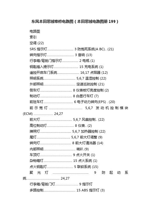
东风本田思域维修电路图(本田思域电路图册199)电路图索引空调 (22)SRS 指示灯................................ 3 防抱死系统(A BC).. (21)转向指示灯................................. 3 音响 (13)行李箱/背舱门指示灯.................... 2 电瓶 (1)钥匙插入提示灯.............................. 15 充电系统 (1)遥控开启车门系统........................... 16,17 点烟器 (12)照明系统....................................... 5,6,7 温湿控制 (22)外部照明....................................... 定速巡航控制 (21)倒车灯....................................... 8 仪表板灯亮度控制 (2)制动灯....................................... 8 白昼行车灯 (7)前驻车灯.................................... 6 电子动力转向(EPS) . (20)前示宽灯……………………………… 5,6,7 发动机控制模块(ECM) ………………… 24,27前大灯....................................... 5,6,7 风扇控制.. (22)高位制动灯................................. 8 仪表.. (2)牌照灯...................................... 5,6,7 加热器控制 (22)尾灯......................................... 5,6,7 前大灯调整 (9)转向灯...................................... 8 前大灯清洗器 (14)内部照明....................................... 喇叭 (9)车顶灯....................................... 9 点火开关 (1)杂物箱灯................................... 15 点火系统 (1)点火钥匙灯................................ 5 联锁系统 (15)聚光灯………………………………... 9 防起动系统……………………………… 24,27行李箱/背舱门灯……………………. 9 指示灯多路控制....................................... 15 ABS 指示灯 (3)动力系统控制模块(PCM) .................. 24,27 A/T 档位指示灯 (4)电动车门锁.................................... 16,17 定速巡航指示灯 (3)电动后视镜.................................... 10 车门指示灯 (2)电动车窗....................................... 11 EPS 指示灯.. (3)后窗除雾器.................................... 22,23 前雾灯指示灯 (3)座椅加热器.................................... 13 远光指示灯 (3)防盗安全控制................................. 18,19 燃油量少指示灯 (2)换档锁定系统................................. 15 低机油压力指示灯 (2)高级锁定系统................................. 16 异常、需修理指示灯 (2)起动系统....................................... 1 故障指示灯 (3)辅助保护系统(SRS) ........................ 20 后雾灯指示灯 (3)转向信号/危险报警灯....................... 8 座椅安全带提示灯 (2)车速传感器(VSS) ........................... 2 侧安全气囊指示灯 (3)刮水器/清洗器 (14)汽车技师帮技术资料东风本田思域维修电路图(本田思域电路图册199)。
2007款东风本田思域转向系统维修手册

转向系统动力转向专用工具............................................................................. 17-2 组件位置索引 ..................................................................... 17-3 故障症状处理索引.............................................................. 17-4 症状故障处理 ..................................................................... 17-6 转向盘转向行程的检查....................................................... 17-7 动力转向助力检查.............................................................. 17-7 转向联动装置和转向机的检查............................................ 17-8 转向泵压力测试.................................................................. 17-9 转向油泄漏检查.................................................................. 17-11 转向油的更换 ..................................................................... 17-12 动力转向软管、管路及压力开关的更换 ............................. 17-13 动力转向泵的更换.............................................................. 17-14 动力转向泵大修.................................................................. 17-16 转向盘的拆卸 ..................................................................... 17-23 转向盘的拆解/重新安装...................................................... 17-24 转向盘安装......................................................................... 17-25 转向柱盖的拆卸与安装....................................................... 17-26 转向柱拆卸与安装.............................................................. 17-27 转向柱/倾斜装置/调节杆的检查.......................................... 17-30 转向锁止机构的更换 .......................................................... 17-30 齿条导块调节 ..................................................................... 17-31 转向机的拆卸 ..................................................................... 17-32 转向机的大修 ..................................................................... 17-37 转向机的安装 ..................................................................... 17-53 横拉杆球头防护套的更换................................................... 17-57 转向机装配垫的更换 .......................................................... 17-58动力转向专用工具序号工具编号工具名称数量07HAG–SF10100活塞密封圈导套 107HAG–SF10200活塞密封圈尺寸校正工具 107JAF–SH20330轴衬底座 107MAA–SL00100锁螺母扳手,40 mm 107MAC–SL00201或07MAC–SL00200移动球连接体,28 mm 107NAD–SR30101传动手柄 107NAD–SR30200 移动包装帽头 107NAG–SR30900 胶料环阀 107RAK–S040111 P/S连接适配器(泵) 107RAK–S040122 P/S连接适配器(软管) 107ZAB–S5A0100 皮带轮紧固器 107ZAG–S5A0300 油缸端盖密封件滑块 107406–0010001 支管压力表组合 107746–0010100 传动附件,32 × 35 mm 107746–0010300 传动附件,42 × 47 mm 107749–0010000 传动手柄 107974–SA50200 轴套密封圈尺寸校正工具 107974–SA50800 球头防护套卡夹导套 117-217-3组件位置索引图示为左侧驾驶型,右侧驾驶型与之对称。
款东风本田思域发动机燃油与排放系统维修手册(9)
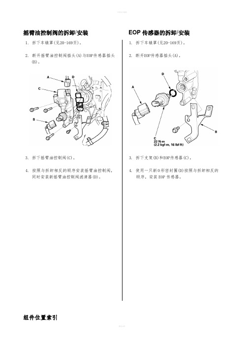
摇臂油控制阀的拆卸/安装EOP传感器的拆卸/安装1. 拆下车辕罩(见20-169页)。
2. 断开摇臂油控制阀插头(A)与EOP传感器插头(B)。
3. 拆下摇臂油控制阀(C)。
4. 按照与拆卸相反的顺序安装摇臂油控制阀,同时安装新摇臂油控制阀滤清器(D)。
1. 拆下车辕罩(见20-169页)。
2. 断开EOP传感器插头(A)。
3. 拆下支架(B)和EOP传感器(C)。
4. 使用一只新O形密封圈(D)按照与拆卸相反的顺序,安装EOP传感器。
组件位置索引*:图中所示左侧驾驶型。
*:图中所示左侧驾驶型。
动力转向压力(PSP)开关信号电路故障处理,见11-267页A/C压缩机离合器继电器(A)信号电路故障处理,见11-265页A/C压缩机A/C压力传感器交流发电机信号电路故障处理,见11-266页制动踏板位置开关信号电路故障处理,见11-269页DTC故障处理DTC P0532:A/C压力传感器电路电压低说明:进行故障处理之前,先记录冻结故障数据以及所有仪表快摄数据,再查阅一般故障处理说明(见11-3页)。
1. 打开点火开关至ON(II)。
2. 使用HDS在数据表(DATA LIST)中检查A/C压力传感器。
电压是否约为0.3V或更低?是-进行第3步。
否-间歇性故障,此时系统正常。
检查A/C 压力传感器与ECM/PCM处端子连接是否良好或松动。
■3. 关闭点火开关。
4. 断开压力传感器3芯插头。
5. 打开点火开关至ON(II)。
6. 使用HDS在数据表(DATA LIST)中检查A/C压力传感器。
电压是否约为0.3V或更低?是-进行第8步。
否-进行第7步。
7. 测量A/C压力传感器3芯插头1号端子与3号端子之间的电压。
A/C压力传感器3芯插头凹头插头导线侧电压是否约为5V?是-进行第16步否-进行第12步。
8. 关闭点火开关。
9. 使用HDS短接SCS线。
10. 断开ECM/PCM插头A(44芯)。
11. 检查A/C压力传感器3芯插头2号端子与车身地线之间的导通性。
本田思域GX车主手册 - 保养和维护说明书

Avoid exceeding your vehicle’s load limit.This puts excess stress on the engine,brakes,and many other parts of your vehicle.The load limit is shown on the label on the driver’s doorjamb.Your vehicle displays engine oil life and maintenance service items on the information display to show you when you should have your dealer do engine oil replacement and indicated maintenance service.The fuel system is under highpressure (maximum 3,600psi/24,800kPa).It has no user-serviceable parts,and its components must not be modified.Whenever fuel system maintenance is required,take your vehicle to an authorized Honda Civic GX dealer,or a qualified NGV technician.Refer to the important safetyprecautions and instructions in the Civic Sedan owner’s manual.Operate your vehicle onreasonable roads within the legal speed limit.Drive your vehicle regularly over a distance of several miles (kilometers).Maintenance MinderTo see the current engine oil life, turn the ignition switch to the ON (II)position,and press the SEL/ RESET button repeatedly until the engine oil life display appears.The maintenance item code or codes indicate the main and sub items required at the time of the oil change.CONTINUEDEngine Oil Life Display Maintenance MinderIf you have the required service done but do not reset the display, or reset the display without doing the service, the system will not show the proper maintenance intervals. This can lead to serious mechanical problems because you will no longer have an accurate record of when maintenance is needed.We recommend using Honda parts and fluids whenever you have maintenance done. These are manufactured to the same high quality standards as the original components, so you can be confident of their performance and durability.However, service at a dealer is not mandatory to keep your warranties in effect. Maintenance may be done by any qualified service facility or person who is skilled in this type of automotive service. Make sure to have the service facility or person reset the display as previously described. Keep all receipts as proof of completion, and have the person who does the work fill out the maintenance record or the Honda service history booklet. Check your warranty booklet for more information.When the remaining engine oil life is5 to 1 percent, you will see a ‘‘SERVICE OIL LIFE’’ message along with the same maintenance item code(s),every time you turn the ignition switch to the ON (II)position.For information on maintenance codes,see page ,or refer to the Civic Sedan owner’s manual.Your authorized Honda dealer knows your vehicle best and can provide competent,efficient service.For information on resetting the maintenance minder,refer to the Civic Sedan owner’s manual.19Important Maintenance Precautions Maintenance MinderMaintenance Minder:Independent of the maintenance messages in the information display,replace the brake fluid every 3 years.Inspect idle speed every 160,000 miles (256,000 km).If sub-item 2 does not appear more than 36 months after the display is reset,inspect the fuel tank every 3 years.See Fuel Tank on page 23 for inspection and replacement information.The fuel tank should be replaced 15 years after it was manufactured.Adjust the valves during services A, B, 1, 2, or 3 only if they are noisy.Seeinformation on maintenance and emissions warranty in the second column on page of the Civic Sedan owner’s manual.NOTE:2:218MaintenanceMinderMaintenance Recordmi mi mi mi mi mi mi mi mi mi mi mi mi miYou or the servicing dealer can record all completed maintenance here.When maintenance is performed,record the mileage,circle the coded item(s) completed,and write in any other non-coded items(such as brake fluid replacement)below the codes.Keep the receipts for all work done on your vehicle.Maintenance can also be recorded in your Honda service history booklet.MileagekmkmkmkmkmkmkmSignatureDateMileagekmkmkmkmkmkmkmSignatureDate MaintenancePerformedA B12345A B12345A B12345A B12345A B12345A B12345A B12345MaintenancePerformedA B12345A B12345A B12345A B12345A B12345A B12345A B12345Maintenance Recordmi mi mi mi mi mi mi mi mi mi mi mi mi miMileagekmkmkmkmkmkmkmSignatureDateMileagekmkmkmkmkmkmkmSignatureDate MaintenancePerformedA B12345A B12345A B12345A B12345A B12345A B12345A B12345MaintenancePerformedA B12345A B12345A B12345A B12345A B12345A B12345A B12345Engine coolant change capacity:The SAE number tells you the oil’sviscosity or weight.Select theoil for your vehicle accordingto this chart.Refer to the Civic Sedan owner’s manual for engine coolant checking and adding procedures.Engine OilEngine CoolantEngine Oil,Engine Coolant1.37US gal (5.2)。
东风本田思域发(2007款)原厂发动机机械维修手册
发动机机构发动机总成专用工具...........................................................................5-2 发动机的拆卸....................................................................5-3 发动机安装.......................................................................5-11 发动机侧支架的更换.........................................................5-21 变速箱支架的更换.............................................................5-25 下部扭力杆的更换.............................................................5-27 上部扭力杆的更换.............................................................5-29 发动机侧装配座支架的更换..............................................5-29缸盖...............................................................6-1发动机体........................................................7-1发动机的润滑.................................................8-1进气歧管与排气系统......................................9-1发动机总成5-2专用工具序号 工具编号工具名称数量07KAK-SJ40101 07KAK-SJ40200 07MAK-PY30100发动机升降挂钩装置发动机挂钩支架 发动机挂钩支架1 1 1发动机的拆卸所需专用工具· 发动机挂钩支架 07MAK-PY30100· 发动机升降挂钩装置 07KAK-SJ40101· 发动机挂钩支架 07KAK-SJ40200说明:· 使用翼子板盖,以避免损坏油漆表面。
东风本田思域(2007款)音响与视频系统维修手册

音频和视频系统音频系统组件位置索引 ..................................................................... 23-2 系统说明............................................................................. 23-3 电路图 ................................................................................ 23-8 自诊断程序......................................................................... 23-10 错误代码............................................................................. 23-12 故障症状索引 ..................................................................... 23-13 故障症状处理 ..................................................................... 23-14 音频装置的拆卸/安装 ......................................................... 23-30 扬声器的更换 ..................................................................... 23-33 辅助音频耳机插口总成的更换............................................ 23-34 收音机遥控开关的测试....................................................... 23-35 天线模块的更换.................................................................. 23-35 车窗天线的维修.................................................................. 23-36 收音机遥控开关的更换....................................................... 23-36音频系统23-2组件位置索引右高频扬声器 更换,见23-33页音频装置插头输入输出,见23-5页 拆卸/安装,见23-30页左高频扬声器 更换,见23-33页收音机遥控开关 更换,见23-36页 测试,见23-35页左后扬声器更换,见23-34页车窗天线更换,见23-36页右后扬声器更换,见23-34页天线模块更换,见23-35页天线引入线(AAM/FM)左前车门扬声器 更换,见23-33页辅助天线引入线(AAM/FM)右前车门扬声器 更换,见23-33页 辅助音频耳机插口总成 插头输入与输出,见23-7页 更换,见23-34页图中所示左侧驾驶型,右侧驾驶型与此相似。
东风本田思域车身维修维修手册(2007本田思域混合动力车身修.
参考符号
更换
在批量生产车身焊接图与拆卸/安装图中,符号具备下列含义。
批量生产车身焊接图
拆卸/安装图
说明:
·焊接符号不指明具体的焊接部位。
·具体焊接部位,参见批量生产车身焊接图。车身尺寸图
车身测量尺寸指的是定位轮毂前缘或上缘之间与/或大样图中所示孔之间的距离。
黑点:测量点
点焊节距
MIG焊接长度单位:mm (in.
警告
未严格遵循操作说明和操作前注意事项将会导致自己严重受伤,甚至死亡。
认真遵循本手册中规定的步骤和操作前注意事项。
以下是日常维修工作中一些最重要的安全注意事项。但是将实施维修和修理步骤过程中可能出现的
一切危险逐一提出警告是不可能的,只有维修人员
本人才能够确定是否该执行接受的任务。
重要的安全注意事项·确认你本人已经清晰地了解所有基本的维修店
关于安全
维修说明
本手册中包含的维修及修理说明仅供具备资格的专业修理工使用。在未受过适当培训以及未具备适
当工具和设备的情况下,试图进行维修或修理工作
将会导致自己或他人受伤,而且还会损坏车辆或造
成不安全隐患。
本手册详细说明维修、保养及修理时的正确方法和
步骤。在实施某些步骤时,需要使用专门的工具和
指定设备。任何试图使用不在东风本田推荐范围之
特别说明
警告
如果不严格遵循操作说明,会导致严重人身伤亡。
注意事项
未严格遵循操作说明会导致人身伤害。
说明:提供有用信息。
注意事项
本手册不包括标准维修程序、安全规则及维修操作详细内容。请注意,本手册对造成人身伤害、车辆损坏或不安全维修方法的警告和注意内容进行详细说明。请注意,上述警告内容不可能对所有可能的维修方法进行具体说明,无论是否由东风本田推荐,不可能对所有可能方法的可能危险进行说明,东风本田也不可能对所有方法进行调查。任何人使用由东风本田推荐或非东风本田推荐的维修程序或工具时,必须确保不会对人身安全或车辆安全造成危害。
款本田思迪CITY车身电气系统维修手册--原厂精品资料
2009款本田思迪CITY车身电气系统维修手册--原厂精品资料62TM000B-4.book Page 0 Thursday, November 27, 2008 10:26 PM车身电气系统车身电气系统* 喇叭专用工具.................................................. 22-2 部件位置索引 ........................................... 22-136一般故障排除信息.................................... 22-3 电路图...................................................... 22-138DTC 故障排除索引.................................... 22-17喇叭测试 / 更换......................................... 22-139喇叭开关测试 ........................................... 22-140继电器和控制单元位置 ............ 22-20车外灯线束和搭铁位置...................... 22-25 部件位置索引 ........................................... 22-142电路图...................................................... 22-146保险丝/ 继电器盒 ................... 22-43DTC 故障排除 .......................................... 22-151电源分布............................... 22-46MICU 输入测试 ........................................ 22-161组合灯开关测试 / 更换.............................. 22-164搭铁分布............................... 22-61 大灯调平电机输入测试 ............................. 22-166大灯调整................................................... 22-167* 仪表板下保险丝/ 继电器盒大灯更换................................................... 22-169拆卸和安装............................................... 22-71 灯泡更换................................................... 22-169尾灯更换................................................... 22-171蓄电池牌照灯更换 ............................................... 22-172蓄电池测试............................................... 22-72 牌照灯灯泡更换........................................ 22-172蓄电池端子断开 / 重新连接.......................22-74 高位制动灯更换........................................ 22-173蓄电池拆卸/ 安装.................................... 22-75 制动踏板位置开关测试 ............................. 22-173大灯调平开关测试 / 更换 .......................... 22-174继电器大灯调平电机更换 .................................... 22-174功率继电器测试 ........................................ 22-76雾灯* 点火开关部件位置索引 ........................................... 22-175测试.......................................................... 22-77 电路图...................................................... 22-176更换.......................................................... 22-77 MICU 输入测试 ........................................ 22-177多路集成控制系统前雾灯更换 ............................................... 22-179前雾灯灯泡更换........................................ 22-179部件位置索引............................................ 22-78前雾灯调整 ............................................... 22-180系统说明................................................... 22-79自诊断功能............................................... 22-88 转向信号/ 危险警告灯电路图....................................................... 22-92部件位置索引 ........................................... 22-181DTC 故障排除........................................... 22-94系统说明................................................... 22-183MICU 输入测试 ........................................ 22-101电路图...................................................... 22-184无钥匙/ 电动门锁/ 安全系统DTC 故障排除 .......................................... 22-186MICU 输入测试 ........................................ 22-188部件位置索引............................................ 22-105侧转向信号灯更换 .................................... 22-191系统说明................................................... 22-107危险警告开关测试 / 更换 .......................... 22-192电路图....................................................... 22-110DTC 故障排除........................................... 22-114 车内照明灯症状故障排除索引..................................... 22-117 部件位置索引 ........................................... 22-193症状故障排除............................................ 22-118 电路图...................................................... 22-194MICU 输入测试........................................ 22-120 独立阅读灯测试 / 更换.............................. 22-195门锁作动器测试........................................ 22-125 顶灯测试 / 更换......................................... 22-195燃油箱盖锁作动器测试 .............................22-127 行李厢灯测试/ 更换 ................................. 22-196如何使燃油箱盖锁作动器摆脱困境 ........... 22-127 行李厢盖锁闩开关测试 ............................. 22-196燃油箱盖锁作动器更换 .............................22-128门锁按钮开关测试..................................... 22-129 仪表照明车门锁芯开关测试..................................... 22-130 电路图...................................................... 22-197防盗报警喇叭测试/ 更换...........................22-131发动机盖开关测试..................................... 22-131 上车照明灯控制系统行李厢锁芯开关测试................................. 22-132 部件位置索引 ........................................... 22-198发射器测试............................................... 22-133 电路图...................................................... 22-199触发传感器读取........................................ 22-135MICU 输入测试 ........................................ 22-201点火钥匙开关测试 .................................... 22-20462TM000B-4.book Page 1 Thursday, November 27, 2008 10:26 PM电动车窗附件电源插座部件位置索引............................................ 22-205 部件位置索引 ........................................... 22-289系统说明................................................... 22-206 电路图...................................................... 22-290电动车窗控制单元重新设定......................22-207 附件电源插座测试/ 更换 .......................... 22-291电路图....................................................... 22-208电动车窗总开关输入测试 .........................22-210 电动后视镜电动车窗总开关测试................................ 22-213 部件位置索引 ........................................... 22-292乘客侧电动车窗开关输入测试 ..................22-214 电路图...................................................... 22-294驾驶员侧电动车窗电机测试 .....................22-215 功能测试................................................... 22-296乘客侧电动车窗电机测试..........................22-216 电动后视镜开关测试/ 更换....................... 22-297电动车窗总开关更换................................. 22-217 电动后视镜作动器测试 ............................ 22-298前排乘客侧电动车窗开关更换...................22-217 电动后视镜作动器更换............................. 22-299后排电动车窗开关更换 .............................22-218 后窗除雾器刮水器/ 清洗器部件位置索引 ........................................... 22-302电路图...................................................... 22-303部件位置索引............................................ 22-219开关测试 / 更换......................................... 22-304电路图....................................................... 22-220功能测试................................................... 22-305DTC 故障排除........................................... 22-221除雾器电阻丝修理 ................................... 22-306MICU 输入测试 ........................................ 22-235刮水器 / 清洗器开关测试 / 更换.................22-238 发动机防盗锁止系统刮水器电机测试....................................... 22-239 部件位置索引 ........................................... 22-307清洗器电机测试....................................... 22-239 系统说明................................................... 22-309刮水器电机更换....................................... 22-240 一般故障排除信息 .................................... 22-310刮水器臂更换........................................... 22-242 电路图...................................................... 22-312清洗器储液罐更换..................................... 22-242 DTC 故障排除 .......................................... 22-313刮水器刮片更换....................................... 22-243 症状故障排除 ........................................... 22-315刮水器臂/ 喷嘴调整.................................. 22-244 系统检查................................................... 22-318清洗器管更换............................................ 22-245 发动机防盗锁止无钥匙控制单元输入仪表测试 ..................................................... 22-320发动机防盗锁止无钥匙控制单元更换 ....... 22-322部件位置索引............................................ 22-246发动机防盗锁止钥匙注册 ......................... 22-323自诊断功能............................................... 22-248电路图....................................................... 22-252DTC 故障排除........................................... 22-256仪表控制单元输入测试 ............................. 22-267在新的仪表控制单元上重写 ODO 数据..... 22-269仪表控制单元更换..................................... 22-270安全指示灯系统部件位置索引............................................ 22-271电路图....................................................... 22-272控制单元输入测试..................................... 22-273提醒系统部件位置索引............................................ 22-276电路图....................................................... 22-278控制单元输入测试..................................... 22-281点烟器部件位置索引............................................ 22-286电路图....................................................... 22-287点烟器测试/ 更换 ..................................... 22-28862TM000B-4.book Page 2 Thursday, November 27, 2008 10:26 PM车身电气系统专用工具参考号工具号码说明数量A 07WAZ-0010100 MPCS 短路插接器1B 07TAZ-001020A 背部探针适配器2C 07MAJ-SP00400 无钥匙上车检验器122-262TM000B-4.book Page 3 Thursday, November 27, 2008 10:26 PM一般故障排除信息技巧和注意事项 ? 有些插接器的侧面有一个卡扣,用于将插接器连接到车身或另一部件上的支座托架。
东风本田思域(2007款)制动系统维修手册

制动系统基本制动组件专用工具............................................................................. 19-2 组件位置索引 ..................................................................... 19-3 制动系统的检查与检测....................................................... 19-4 症状故障处理 ..................................................................... 19-5 制动踏板和制动踏板位置开关的调节................................. 19-6 驻车制动的检查与调节....................................................... 19-7 制动系统的排气.................................................................. 19-10 制动系统指示灯电路图....................................................... 19-11 驻车制动开关的检测 .......................................................... 19-12 制动液液位开关的检测....................................................... 19-12 前制动片的检查与更换....................................................... 19-13 前制动盘的检查.................................................................. 19-17 前制动器卡钳的大修 .......................................................... 19-18 制动总泵的更换.................................................................. 19-19 制动总泵的拆解.................................................................. 19-20 制动总泵的重新组装 .......................................................... 19-22 制动助力器的检查.............................................................. 19-25 制动助力器的更换.............................................................. 19-27 后制动片的检查与更换....................................................... 19-31 后制动盘的检查.................................................................. 19-34 后制动卡钳的大修.............................................................. 19-35 后鼓式制动器的检查 .......................................................... 19-36 后制动蹄的更换.................................................................. 19-38 后轮制动缸的拆解/检查...................................................... 19-41 制动踏板的更换.................................................................. 19-42 制动软管和管路的检查....................................................... 19-43 制动软管的更换.................................................................. 19-44 驻车制动拉线的更换 .......................................................... 19-46 驻车制动拉杆驻车杆和罩的更换........................................ 19-48ABS(防抱死制动系统)组件............................ 19-51基本制动组件19-2专用工具序号 工具编号 工具名称数量07404-5790301 07406-5790201 07410-5790101 07410-5790501 07510-6340101真空表 压力表 附件管接头适配器压力表连接管,10 x 1.0 mm1 2 2 1 219-3组件位置索引图示为左侧驾驶型,右侧驾驶型与之对称。
本田车身修复手册-焊接和切割指南修订版说明书
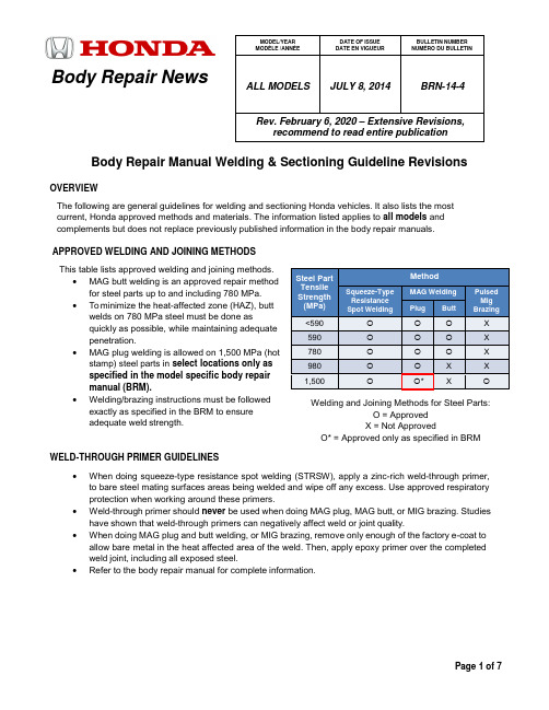
Body Repair NewsBody Repair Manual Welding & Sectioning Guideline RevisionsOVERVIEWThe following are general guidelines for welding and sectioning Honda vehicles. It also lists the most current, Honda approved methods and materials. The information listed applies to all models and complements but does not replace previously published information in the body repair manuals.APPROVED WELDING AND JOINING METHODS This table lists approved welding and joining methods.• MAG butt welding is an approved repair methodfor steel parts up to and including 780 MPa. • To minimize the heat-affected zone (HAZ), buttwelds on 780 MPa steel must be done asquickly as possible, while maintaining adequate penetration.• MAG plug welding is allowed on 1,500 MPa (hotstamp) steel parts in select locations only as specified in the model specific body repair manual (BRM).• Welding/brazing instructions must be followedexactly as specified in the BRM to ensure adequate weld strength.WELD-THROUGH PRIMER GUIDELINES•When doing squeeze-type resistance spot welding (STRSW), apply a zinc-rich weld-through primer, to bare steel mating surfaces areas being welded and wipe off any excess. Use approved respiratory protection when working around these primers.• Weld-through primer should never be used when doing MAG plug, MAG butt, or MIG brazing. Studies have shown that weld-through primers can negatively affect weld or joint quality.•When doing MAG plug and butt welding, or MIG brazing, remove only enough of the factory e-coat to allow bare metal in the heat affected area of the weld. Then, apply epoxy primer over the completed weld joint, including all exposed steel.•Refer to the body repair manual for complete information.MODEL/YEAR MODÈLE /ANNÉE DATE OF ISSUE DATE EN VIGUEUR BULLETIN NUMBER NUMÉRO DU BULLETINALL MODELS JULY 8, 2014 BRN-14-4Rev. February 6, 2020 – Extensive Revisions,recommend to read entire publicationSteel Part Tensile Strength (MPa) MethodSqueeze-Type Resistance Spot WeldingMAG Welding Pulsed Mig BrazingPlugButt<590 X 590 X 780 X 980 X X 1,500*XWelding and Joining Methods for Steel Parts:O = Approved X = Not ApprovedO* = Approved only as specified in BRMMAG WELDING WIRE SELECTION GUIDELINES•Welding wire used during high-strength-steel repair must have a tensile strength equal to or greater than the lowest tensile strength of the parts being welded.•Typical ER70S-6 wire has a minimum tensile strength of 70 ksi (483 MPa). This wire can be used when welding up to 440 MPa steel parts.• This table shows the relationship of steel tensile strength (MPa) to the minimum welding wire tensile strength (ksi).HIGH-STRENGTH MAG WELDING WIREThe following are approved high-strength-steel welding wires:• Bohler Union X96Bohler Union X96Honda Tools & Equipment Program 1-866-868-3372Pro Spot https://Chief AutomotiveAuthorized Chief Automotive Canadian DistributorNOTES:• Bosch DS980J solid welding wire is no longer available but can still be used.•Wire has a size of 0.8 mm (0.030 inch) in diameter and is used for welding joints in high-strength steel of 590 MPa and higher. It may be used for welding lower grade steel, but it is not necessary to provide the required strength.1,500 MPA ULTRA-HIGH-STRENGTH (HOT STAMPING) WELDING CONDITIONSFor an explanation of 1,500 MPa ultra-high-strength (Hot Stamping) steel sheets, refer to the section, Ultra-High- Strength Steel Sheets 1,500MPa grade (hot stamping) in the body repair basics manual. Removal of Aluminum Coating1,500 MPa hot stamp steel sheets have a 10-micron aluminum coating that must be removed (sanded off) from the weld zone of the panel before welding. Both exterior and mating surfaces require the removal of coating. Failure to do so will create a weak weld and ultimately a failure of the joint. NOTE:It is only necessary to sand down the area to be welded.590>86780 >113 980>142(1,000 psi = 1 ksi)SPOT WELDING CONDITIONS FOR 1,500 MPA ULTRA HIGH-STRENGTH STEEL PARTSWhen spot-welding 1,500 MPa steel parts, you must manually set the welder to the conditions listed below. The required welding conditions will be noted in the model specific body repair manual.NOTE:For the actual settings of the welder, refer to the specifications supplied by the welder manufacturer.1 6500 300 2452 (250) 17 8500 700 3432 (350)2 7000 300 2452 (250) 18 9000 700 3432 (350)3 7500 300 2452 (250) 19 9500 700 3432 (350)4 6500 400 2942 (300) 20 8500 800 3432 (350)5 7000 400 2942 (300) 21 9000 800 3432 (350)6 7500 400 2942 (300) 22 9500 800 3432 (350)7 8000 400 2942 (300) 23* 10500 700 3432 (350)8 7000 500 3432 (350) 24* 10500 800 3432 (350)9 7500 500 3432 (350) 25* 8000 1500 3432 (350)10 8000 500 3432 (350) 26* 8000 800 3432 (350)11 8500 500 3432 (350) 27 8500 1500 3432 (350)12 7500 600 3432 (350) 28 7500 800 3432 (350)13 8000 600 3432 (350) 29 8000 1200 3432 (350)14 8500 600 3432 (350) 30 8500 1200 3432 (350)15 9000 600 3432 (350) 31 9000 1200 3432 (350)16 8000 700 3432 (350)NOTES:•Condition numbers with an asterisk are currently not used by any Honda models at the time of this publication.•The condition numbers of the above list show the type of the spot welding conditions of the spot welding points including the ultra-high-strength steel (1,500 MPa/1,180 MPa) parts of Hondavehicles.•The welding condition values described in the above list are determined by experiments using test pieces, zinc primer coating, preheat, and specified tip shapes (Round-16).•For spot welds involving 1,500 MPa steel parts, manual spot welder settings provided in the model specific body repair manual or other Honda service information are required. Honda does notrecommend using the spot welder’s AUTO mode for this steel grade because these settings maynot achieve adequate weld strength.SHIELDING GAS REQUIREMENTSNOTE:In this publication and the body repair manuals, gas metal arc welding (GMAW) is referred to by the following subtypes:MIG Brazing = Metal Inert Gas (MIG) Brazing•The required MIG brazing shielding gas is 100% argon (Ar).•Argon is inert and does not react with the molten braze pool or brazing operation.MAG Welding = Metal Active Gas (MAG) Welding•The preferred shielding gas is C20. A mixture of 80% argon (Ar) and 20% carbon dioxide (CO2), C20 produces a more stable arc, less weld spatter, and better weld quality/appearance.•C25 shielding gas, a mixture of 75% argon (Ar) and 25% carbon dioxide (CO2), is also acceptable. These are considered active gases because CO2 undergoes a limited reaction with the molten weld pool.USE OF HEAT DURING BODY STRAIGHTENING AND REPAIRWhen you are doing body straightening and repair procedures, follow these guidelines:•Never use open flame to heat body panels. However, use of induction heaters, copper stamp or heat guns are acceptable up to 1,100°F (600°C).•Any parts that had heat applied above 1,100°F (600°C) degrees must be replaced with a new parts.•Ignoring these instructions may significantly reduce occupant protection in any subsequent c ollision.PARTIAL PANEL REPLACEMENT AT FACTORY SEAMSThe following guidelines do not apply to ultra-high-strength steel assemblies (980-1,500 MPa) such as the front door ring (outer stiffener ring) and some rear frame rails. These panels should never be disassembled and partially installed. Assemblies must be replaced as a complete set.When you are determining whether to replace a body part as supplied, or do a partial replacement at the factory seams, follow these guidelines:•Replacement of body service parts as supplied at factory seams is the preferred repair method, except when it may cause unnecessary or excessive intrusion into the body structure.•In these cases, the service part may be disassembled at factory seams as required to replace only the damaged portion.•For example, if only the vehicle’s rear wheelhouse is damaged, that part may be removed from the rear inner panel service part assembly at the factory seams and installed on the vehicle.•Replacement procedures for rear inner panels are not provided in the body repair manuals because they are rarely installed as a complete unit.•All basic welding and sectioning guidelines specified in available service information must be observed during partial panel replacement.STEEL PARTS SECTIONING GUIDELINESReplacement of steel parts at factory seams and matching the replacement part configuration remain the preferred repair methods. However, these methods alone are not always practical nor cost effective in all body repair situations. While some limited sectioning procedures are provided in the body repair manual, it is not possible to develop published procedures covering every type and angle of impact. The guidelines detailed below are intended as “basic rules” for properly trained collision repair professionals to use when sectioning steel parts.Various high-strength and ultra-high-strength steel materials with different sheet thicknesses and strengths are applied in many places that vary with body design in order to increase collision safety performance, body stiffness, and weight reduction. Stiffening members are also applied inside some steel parts (patches, reinforcements, stiffeners, etc.).Follow these guidelines to avoid an unsafe repair:Outer Body Panels•Outer body and floor panels with mild steel 270 MPa and low grade high-strength steel that is less than or equal to 590 MPa, may be sectioned as necessary.•Every collision repair is different and requires sectioning to be done based on the nature of the repair which is why Honda does not provide a specific area to be sectioned. However, some areas like theouter rear panels and side sills show an area to be sectioned. This is a suggestion and not arequirement.•For outer body panels sectioning locations, open butt welds with a 1 mm root gap is suggested and preferred as this is the best joint type for corrosion protection. If proper panel fit-up cannot be achieved,a 40 mm backing panel may be used.All Panels•Depending on the type of vehicle damage, steel parts with a tensile strength of 780 MPa or less may be sectioned if all three of the following conditions are met:1. Sectioning must be done in a single-layer area of the part.2. Multi-layer internal steel reinforcements and stiffeners must not be cut.3. Do not section in load bearing areas, such as engine, transmission, or suspension mounting points.•To determine if a part has a single-layer area that can be sectioned, do the following:– Check the body construction pages in the General Information section of the appropriate body repair manual to determine the steel grade(s) and part configurations of the parts being replaced.– Inspect the original and replacement parts to confirm if there are internal reinforcements and/or stiffeners.– Spot welds not directly on a flange or joint indicate a reinforcement or stiffener inside.– The Replacement section of the body repair manual shows some internal reinforcements as a dotted line.•If any of the above sectioning conditions cannot be met, replace those body structural components (stiffeners, reinforcements, and other multi-layered steel parts) as assemblies that match thereplacement parts configuration.。
思域1. 3L混合动力轿车常见故障排除及维修

思域1. 3L混合动力轿车常见故障排除及维修1. IMA系统维修前的注意事项1) IMA系统(一体式电动机辅助系统)采用高压电路。
在维修IMA系统之前,确保断开电路并隔离IMA系统及其相关部件。
2)如果12V蓄电池已进行充电,或其导线已经断开,或已经重新设置MCM(电动机控制模块),则起动发动机时,IMA蓄电池电量表(BAT)将不显示充电状态。
起动发动机并在驻车档或空档的情况下保持3500~4000r/min的转速,直至电量表(BAT)显示三格电量。
3)关闭蓄电池模块开关之后,等待5s,然后从12V蓄电池上断开负极导线(PDU电容器发电大约需要5 min)。
4)断开高压导线端子之前,使用电压表测量时,确保端子之间的电压低于30V。
5)当未使用绝缘护套进行部件维修时,一定要使用绝缘工具,以防止短路。
2.使用HDS检测DTC1)起动发动机并检查IMA系统指示灯。
2)如果IMA系统指示灯持续亮起,则关闭点火开关,然后将HDS连接在位于驾驶人侧仪表板下方的数据传输插头(DLC)上。
3)打开点火开关至ON(II)位置,确保HDS与车辆、BCM模块与MCM通信。
如果未通信,则处理DLC电路故障。
4)在HDS上选择IMA系统。
5)检查并记录故障码(DTC)。
同时,还要检查冻结故障数据。
然后查看DTC故障,并实施相应的故障处理程序。
3. DTC的清除1)打开点火开关至ON(II)位置,不要起动发动机。
2)使用HDS清除DTC。
4. IMA系统指示灯电路故障处理1)打开点火开关至ON(II)位置,等待2s,并观察IMA系统指示灯。
IMA系统指示灯是否亮起或持续点亮?是→转至第2)步。
否→IMA系统指示灯电路正常。
2)使用HDS检查临时DTC或DTC。
是否显示临时DTC或DTC?是→转至显示的DTC故障处理。
否→转至第3)步。
3)进行仪表自诊断功能。
IMA系统指示灯是否闪烁?是。
转至第4)步。
否弓使用运行良好的仪表控制模块替换并重新检查。
思域空滤维修手册
思域空滤维修手册当车辆出现以下故障时,应检查发动机燃油系统是否存在问题:①燃油供油量过低;②喷油器有故障;③点火线圈、火花塞等部件有问题;④点火时间不正常;⑤火花塞积碳过多,甚至已经烧穿了。
如果出现以上现象时,应首先检查节气门位置传感器、燃油泵工作是否正常。
1. 在拆下节气门位置传感器的同时,把燃油泵拆下检查是否正常,如不正常,则将燃油喷射压力调节阀调至最大压力。
(最大压力不能超过额定压力的75%,如果超出应进行维修。
注:使用燃油喷射压力调节阀时,可将调节阀调至最大压力,同时把节气门调到关闭位置)如有可能则更换燃油泵。
如果发现燃油系统不能正常工作,则应检查喷油器和点火线圈是否存在故障。
2. 用手转动燃油泵进油管的阀门杆(或将喷油器开关由关闭状态佇到开启状态),检查是否有燃油进入节气门。
如果有燃油进入,则必须清除干净。
检查燃油压力传感器的工作情况。
打开引擎盖,将仪表上压力传感器的信号指示插头插到进气歧管上,若仪表压力指示灯不亮,则说明该信号不正常,应更换燃油泵(燃油泵的工作原理和节气门位置传感器基本相同)。
检查燃油泵油嘴是否有供油或燃油被吸入。
若在此情况下有供油或燃油被吸入,则需更换燃油滤清器,否则发动机将无法正常工作。
3. 把发动机熄火,在发动机温度达到80°C以上的时候,拆下发动机燃油喷油器的空气滤清器盖检查是否有积炭、积碳、油泥等。
在温度高于80°C的时候,使用清洗剂清洗喷油器、油道,用汽油将清洗剂喷到滤清器的进气管和进气歧管上,然后装回空滤盖。
拆下空滤检查:空气滤清器内是否有积炭、积碳、油泥等。
用压缩空气吹干净滤清器内的污物,然后使用压缩空气把滤清器内部的污垢清除干净。
在高温状态下检查喷油器工作是否正常:如果进气歧管有积碳时,可将喷油器拧到最大,同时在进气歧管上安装高压清洗嘴,用高压气将进气歧管清洗一遍或多遍。
如果有积碳、油泥时也可使用清洁剂擦拭滤芯,然后装上节气门位置传感器试一试。
- 1、下载文档前请自行甄别文档内容的完整性,平台不提供额外的编辑、内容补充、找答案等附加服务。
- 2、"仅部分预览"的文档,不可在线预览部分如存在完整性等问题,可反馈申请退款(可完整预览的文档不适用该条件!)。
- 3、如文档侵犯您的权益,请联系客服反馈,我们会尽快为您处理(人工客服工作时间:9:00-18:30)。
汽车技师帮技术资料
一般性说明
辅助安全保护系统(SRS)
本车型的辅助安全保护系统(SRS)包括位于转向盘毂中的驾驶席侧安全气囊、杂物箱上部仪表板内的助手 席侧安全气囊、前排座椅安全带收卷器中的安全带张紧器、前排座椅安全带下部固定器中的安全腰带张紧 器、前排座椅靠背侧安全气囊和车顶侧的侧面安全气帘。辅助安全保护系统(SRS)装置与气囊装置隔开, 配备内置传感器。辅助安全保护系统(SRS)组件所在部位进行钢板作业、涂装作业以及维修作业时,应严 格遵守下列注意事项:
警告
未严格遵循操作说明和操作前注意事项将会 导致自己严重受伤,甚至死亡。
认真遵循本手册中规定的步骤和操作前注意 事项。
汽车技师帮技术资料
如何使用本手册
本手册中阐述了2007 Civic Hybrid车型系列事故故障修理内容,并对车身损坏组件的更换进行说明。 请在使用本手册前,通读上述操作说明,熟悉其中的要求及说明。 说明:关于技术规格、导线线束位置、安全支架支撑点等,请参阅 2007 Civic Hybrid 维修手册。 另外我们还编制了下述手册,使维修工作更简单。开始维修前,请务必仔细阅读本手册。 · 车身维修手册—车身涂层维修概要之涂层基本说明 P/N 62PRM30; · 车身维修手册—车身涂层维修概要之车身基本说明 P/N 62BRM30。
如果需要更换组件,应使用具有正确组件编号的纯 正东风本田组件或等效组件。特别提醒不要使用质 量低劣的组件进行更换。
为了用户的安全
正确的维修和保养对于保证用户的安全和车辆的 可靠性是十分重要的。维修车辆过程中的任何错误 或疏忽均会导致操作故障、车辆损坏或他人受伤。
警告
不正确的维修或修理将会造成不安全隐患,导 致用户或他人严重受伤,甚至死亡。 必须严格遵照本手册和其它维修资料中规定的 步骤和操作前注意事项进行维修和修理。
拆下相关组件。 • 必须及时更换任何受损或变形的SRS相关组件。
说明:有关辅助安全保护系统(SRS)相关组件引爆后的工序、辅助安全保护系统(SRS)组件的拆除与更换, 请参见维修手册有关保护系统章节内容。
驾驶席安全气囊
前助手席安全气囊
转向线盘
OPDS 传感器/座椅靠背
前助手席侧安全气囊
右侧碰撞传感器(1 号)
黑点:测量点
黑点
向前
向前
向前
大样图
4 层板焊接
拆卸/安装图
说明: · 焊接符号不指明具体的焊接部位。 · 具体焊接部位,参见批量生产车身焊接图。
点焊 MIG 塞焊 MIG 对接焊或角焊
点焊
车辆维修图中所示测量孔通常为孔的中心。
防锈
下图给出密封剂涂抹部位。
密封位置
减震器罩
车轮罩上部 延伸部分
角焊 MIG 塞焊
• 辅助安全保护系统(SRS)电气线束、插头应与相应的黄色编码保持一致。在对本区域进行修理作业时, 应千万小心,不要损坏线束。
• 在烘干辅助安全保护系统(SRS)组件所处位置周围的涂漆面时,加热温度不得超过1000C(2120F)。 • 如果必需在辅助安全保护系统(SRS)组件周围区域进行强烈撞击或进行高温作业时,应在作业开始前,
ቤተ መጻሕፍቲ ባይዱ
特别说明
警告
如果不严格遵循操作说明,会导致严重人身伤亡。
未严格遵循操作说明会导致人身伤害。 说明:提供有用信息。
注意事项
注意事项
本手册不包括标准维修程序、安全规则及维修操作详细内容。请注意,本手册对造成人身伤害、车辆损 坏或不安全维修方法的警告和注意内容进行详细说明。请注意,上述警告内容不可能对所有可能的维修 方法进行具体说明,无论是否由东风本田推荐,不可能对所有可能方法的可能危险进行说明,东风本田 也不可能对所有方法进行调查。任何人使用由东风本田推荐或非东风本田推荐的维修程序或工具时,必 须确保不会对人身安全或车辆安全造成危害。
• 辅助安全保护系统(SRS)装置(包括安全传感器及安全气囊碰撞传感器)位于仪表板下部、侧安全气囊碰 撞传感器位于每一道车身门槛上。前安全气囊碰撞传感器位于前保险杠左右两端后面。对前纵梁、仪 表板下部及车身门槛进行维修时,应避免铁锤或其他工具的强烈撞击。不得用焊炬等对上述部位加热。
• 在车身中间柱以下部位进行涂装或车身修理作业时,应特别小心。应确保座椅安全带收卷器与张紧器不 受热气枪、焊接装置或喷涂装置的影响。
前助手席侧座椅 安全带张紧器
记忆清除信号(MES)插头(2 芯) (黄色)
辅助安全保护系统(SRS) 装置(配备内置传感器)
驾驶席侧安全气囊 左侧碰撞传感器(1 号)
1-2
前助手席侧安全腰带张紧器 OPDS 装置
前助手席侧座椅固定开关
驾驶席侧座椅安全带张紧器
驾驶席侧安全腰带张紧器
汽车技师帮技术资料
参考
符号
更换
在批量生产车身焊接图与拆卸/安装图中,符号具 备下列含义。
批量生产车身焊接图
点焊 MIG 焊接 2 层板焊接 3 层板焊接 4 层板焊接
点焊节距
MIG 焊接长度 单位:mm (in.)
焊接次数
车身尺寸图
车身测量尺寸指的是定位轮毂前缘或上缘之间 与/或大样图中所示孔之间的距离。
为了自身的安全
因为本手册仅供专业修理工使用,故在此并未对许 多基本的车间安全操作提出警告(例如,热组件— 戴上手套)。若未接受过车间安全培训或未熟练掌 握安全维修操作知识,我们建议不要试图实施本手 册中规定的操作步骤。
以下是日常维修工作中一些最重要的安全注意事 项。但是将实施维修和修理步骤过程中可能出现的 一切危险逐一提出警告是不可能的,只有维修人员 本人才能够确定是否该执行接受的任务。
汽车技师帮技术资料
关于安全
维修说明
本手册中包含的维修及修理说明仅供具备资格的 专业修理工使用。在未受过适当培训以及未具备适 当工具和设备的情况下,试图进行维修或修理工作 将会导致自己或他人受伤,而且还会损坏车辆或造 成不安全隐患。
本手册详细说明维修、保养及修理时的正确方法和 步骤。在实施某些步骤时,需要使用专门的工具和 指定设备。任何试图使用不在东风本田推荐范围之 内的替代组件、工具或采用其他维修步骤的人员, 必须明确,此举是否对其人身安全和车辆的安全行 驶带来危险。
重要的安全注意事项
· 确认你本人已经清晰地了解所有基本的维修店 安全操作规程,并且穿戴相应的服装,使用安 全的设备。在执行任何一项维修任务时,应特 别注意以下事项: - 维修开始前,阅读所有操作说明,并确认自 己具备相应的工具、更换或修理组件,以及 安全、全面地执行该任务所要求的技能。 - 在锤击、钻孔、研磨或工作在加压空气或液 体以及弹簧或其它储能组件周围时,一定要 戴上适宜的防护眼镜、护目镜或护面罩,保 护双眼。如果其它维修工作也可能使眼部受 伤,也应戴上眼部保护物。 - 必要时,使用其它的防护物品,例如,手套 或安全鞋。处理热的或锋利组件可能会造成 严重烧伤或割伤。在需要手握有可能使自己 受伤的任何组件之前,应戴上手套。 - 当举起车辆时应注意自己与他人的安全。当 利用举升机或千斤顶举升车辆时,确保车辆 安全支撑。一定使用千斤顶支架。 - 每次焊接时,要注意戴上经认可的焊接头盔、 手套和安全靴保护自己。你会被热组件灼 伤,因此,到该区域工作前,要使热组件冷 却下来。 - 每次喷漆时,要戴上经认可的防尘口罩、护 目镜和手套。只能在通风良好的烤房内喷 涂。
对接焊
大样图
汽车技师帮技术资料
汽车技师帮技术资料
一般性说明 喷漆说明 * 更换 车身尺寸图 防锈
带星号(*)的部位包含SRS组件,维修时需特别注意。
汽车技师帮技术资料
一般性说明
辅助安全保护系统(SRS) ...................................................1-2 引爆后辅助安全保护系统(SRS)组件的更换/检查 ..............1-4 IMA 系统...........................................................................1-5 识别号码的位置 ................................................................1-8 举升支撑点 .......................................................................1-9 车身规格/车轮定位............................................................ 1-10 汽车外部组件的拆卸/安装 .................................................1-11 车身结构 ...........................................................................1-13 车门与保险杠加强件 .........................................................1-14 镀锌钢板的维修 ................................................................1-15 高强度钢板构架区域及其维修注意事项............................. 1-16
本手册内的所有信息,均以刊印时可得到的最新产品资料为基础。我们保留在任何时候不加通知而进行修 改的权利。未经出版商书面同意,本刊物的任何部分、包括文字、图片和表格,均不得复制,存入检索系 统或以任何方式、不论是电子还是机械方式发送、复印和记录。
东风本田汽车有限公司 售后服务科
2007 年 6 月第一版 102 页 版权所有
