ACL主阀门(SAMSON)3277
SAMSON 3241-1和3241-7气动调节阀维护说明

气动控制阀3241-1型和3241-7型安装与 操作说明EB 8015 ZH图1 · 配3271型和3277型执行机构的3241型气动控制阀 3241-1型3241-7型2007年7月版目录目录页1 结构和工作原理‥‥‥‥‥‥‥‥‥‥‥‥‥‥‥‥‥ 42 装配阀门和执行机构‥‥‥‥‥‥‥‥‥‥‥‥‥‥‥ 42.1 装配和调整‥‥‥‥‥‥‥‥‥‥‥‥‥‥‥‥‥‥‥ 42.2 “执行机构推杆伸出”类型执行机构的预紧弹簧‥‥‥72.3阀门和不同行程范围的执行机构‥‥‥‥‥‥‥‥‥‥83 安装‥‥‥‥‥‥‥‥‥‥‥‥‥‥‥‥‥‥‥‥‥‥93.1安装位置‥‥‥‥‥‥‥‥‥‥‥‥‥‥‥‥‥‥‥‥93.2信号压力管线‥‥‥‥‥‥‥‥‥‥‥‥‥‥‥‥‥‥93.3过滤器、旁路‥‥‥‥‥‥‥‥‥‥‥‥‥‥‥‥‥‥93.4 测试连接‥‥‥‥‥‥‥‥‥‥‥‥‥‥‥‥‥‥‥‥94操作‥‥‥‥‥‥‥‥‥‥‥‥‥‥‥‥‥‥‥‥‥‥95 维修-更换部件‥‥‥‥‥‥‥‥‥‥‥‥‥‥‥‥‥‥105.1标准型阀门‥‥‥‥‥‥‥‥‥‥‥‥‥‥‥‥‥‥‥115.1.1 填料函填料‥‥‥‥‥‥‥‥‥‥‥‥‥‥‥‥‥‥‥115.1.2 阀座和/或阀芯‥‥‥‥‥‥‥‥‥‥‥‥‥‥‥‥125.2 带延长段或金属波纹管密封的阀门‥‥‥‥‥‥‥‥‥135.2.1 填料函填料‥‥‥‥‥‥‥‥‥‥‥‥‥‥‥‥‥‥‥135.2.2 阀芯‥‥‥‥‥‥‥‥‥‥‥‥‥‥‥‥‥‥‥‥‥‥135.2.3 阀座‥‥‥‥‥‥‥‥‥‥‥‥‥‥‥‥‥‥‥‥‥‥155.2.4 金属波纹管‥‥‥‥‥‥‥‥‥‥‥‥‥‥‥‥‥‥‥155.2.5 重新组装‥‥‥‥‥‥‥‥‥‥‥‥‥‥‥‥‥‥‥‥165.3 更换平衡阀芯衬圈或密封‥‥‥‥‥‥‥‥‥‥‥‥‥166材料识别标志‥‥‥‥‥‥‥‥‥‥‥‥‥‥‥‥‥‥187 铭牌说明‥‥‥‥‥‥‥‥‥‥‥‥‥‥‥‥‥‥‥‥198 用户咨询‥‥‥‥‥‥‥‥‥‥‥‥‥‥‥‥‥‥‥‥19此《安装与操作说明》也可配合T 8046-1 ZH数据表,适用于3246型单座阀(Class 150和300)。
3271 型和 3277 型 气动执行机构 安装和操作手册
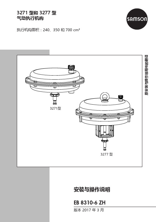
3271 型和 3277 型气动执行机构执行机构面积:240、350 和 700 cm²2 EB 8310-6 ZH安装与操作说明的注解安装与操作说明书就如何安全地安装和操作设备给出说明,用于操作SAMSON的相关设备。
Î为安全且恰当地使用安装与操作说明书,请认真阅读并将其留存备用。
Î如有任何疑问,欢迎致电SAMSON售后服务部门(***************************)。
设备的安装与操作说明将随货发送。
请登陆网站www.samson.de > Product documentation获取文件的最新版本,您可在[Find:]区域内输入文件号或型号查找文件。
标志词释义伤害的危险情况。
伤害的危险情况。
目录1 安全说明和措施 (5)1.1 关于可能发生的严重人身伤害的相关说明 (7)1.2 有关可能发生的人身伤害的说明 (8)1.3 有关可能的财产损失的说明 (9)2 设备上的标记 (10)2.1 执行机构铭牌 (10)3 结构和工作原理 (11)3.1 3271型 (11)3.2 3277 型 (12)3.3 操作方向 (13)3.4 信号压力路线 (13)3.4.1 3271型 (13)3.4.2 3277 型 (13)3.5 故障-安全功能 (13)3.5.1 操作方向为“执行机构推杆伸出”(FA) 的型号 (14)3.5.2 操作方向为“执行机构推杆收回”(FE) 的型号 (14)3.6 类型 (14)3.7 技术数据 (15)4 准备措施 (19)4.1 拆箱 (19)4.2 运输和吊举 (19)4.2.1 运输 (20)4.2.2 提举 (20)4.3 存放 (22)4.4 准备安装 (23)5 安装和启动 (24)5.1 将执行机构安装到阀门上 (24)5.2 预压弹簧 (27)5.2.1 张紧弹簧 (27)5.2.2 增大执行机构止推力 (27)5.2.3 改动行程范围 (28)EB 8310-6 ZH 3目录6 操作 (30)6.1 节流应用 (30)6.2 开/关应用 (30)6.3 操作方向反向 (31)6.3.1 从推杆伸出到推杆收回,操作方向反向 (31)6.3.2 从推杆收回到推杆伸出,操作方向反向 (33)6.4 带手轮类型 (35)6.4.1 手动伸出执行机构推杆 (35)6.4.2 手动收回执行机构推杆 (35)6.5 调节行程限位 (36)6.5.1 底部行程限位(最小行程) (36)6.5.2 顶部行程限位(最大行程) (36)7 维修 (38)7.1 更换膜片 (39)7.2 更换执行机构推杆密封件 (42)7.3 退货装运准备 (44)7.4 订购备件和工作耗材 (45)8 故障 (46)9 停用和拆卸 (48)9.1 停止运行 (48)9.2 从阀门拆下执行机构 (48)9.3 释放执行机构中的弹簧压缩 (48)9.4 处置 (48)10 附录 (50)10.1 售后服务 (50)10.2 备件 (51)4 EB 8310-6 ZH安全说明和措施1 安全说明和措施预期用途SAMSON 3271和3277型执行机构专门应用于单座直通阀上。
SAMSON 3780说明书

SAMSON 3780说明书调节阀维护及操作规程DCS系统对调节阀的控制主要通过调节阀自身的电气阀门定位器完成。
我司生产线上的调节阀为德国SAMS ON调节阀,SAMSON调节阀采用智能数字阀门定位器(3780,HART协议数字通信),其控制精度高,运行稳定。
定位器的主要性能介绍如下:结构与工作原理HART电气定位器是为连接气动调节阀而设计的,它可确保阀杆位置(受控变量)与控制信号(参考变量)之间的对应关系。
它将控制装置 4至20mA的输出信号和调节调的行程相比较,并产生一个相应的压力信号作为输出变量。
为此,用户需要提供辅助气源压力1.4-6巴。
定位器辅助能源是由4到20mA参考变量信号提供。
定位器由一个感应,非接触或位移传感系统,一个由2/2-通开关阀组成的电控阀块以及一个电控单元组成。
电控单元包含两个用于处理控制算法及管理通讯的微控器.一旦实际阀门行程值(实际值)与参考变量(设定点)之间出现偏差,微控器就会产生一个二进制脉冲调制信号去控制两个 2/2通开关阀,且分别由一个指定的放大器来控制。
其中一个阀控制排气,另一个控制气源.气源阀(3)将供气(7气源压力1·46巴)送到执行器(填充)。
排气阀(将执行器排出空气流排放到大气中(排气)。
这些开关阀即可以有开关状态—一常开。
常闭—一也可产生可变宽度的单脉冲。
对于这两个受控_阀门,阀林将会移动到与参考变连量相对应的位置。
如果没有系统偏差气源阀和排气阀都将关闭。
作为一个标准功能,定位器配有一个故障信息输出(根据DDN19Z34,NANUR标准的进制输出),用于向控制室发送故障信号。
成的激活位于定位器铰接盖上的写保护开关‘可防止设定被HART通讯修改。
作为对标准定位器型号的补充,有几个附加的选项用于扩展定位器功能。
带眼位开关的定位器为了在故障一安全电路中指示出阀门的最终位置,两个软件限位开关或两个接近开关被带强制排空功能的定位器一个控制定位器的6-24V电压信号,使得信压力施加到执行器。
SAMSON 操作说明书 4708 减压阀

2 空气过滤减压阀的安装
为防止收集较多的冷凝水,空气压缩机与空 气过滤减压阀之间的距离要尽可能短。要确 认带空气过滤罐的排污塞朝下安装。
2.1 紧凑的空气过滤减压阀
空气过滤减压阀可以直接接至压缩空气管 网,或是使用导轨、托架等相应的安装件(参 见 19 页的第 7 节)。
要注意气源流向,在铭牌处有箭头表示流 向。
3. 在适配板(1)连接孔推入特制空心螺 拴,(6)用于气源 SUPPLY 和(7)用于 输出 OUTPUT。
4. 将空气过滤减压阀放到阀门定位器上, 用两个特制空心螺拴旋紧
5. 用塞子(4)封上备用连接口,防止灰 尘等进入设备
4708-57xx 型用于 3760 型阀门定位 器
对于阀门定位器装配在控制阀支架左侧(参 照黑色转换板)的安装如图示。对于阀门定 位器装配在控制阀支架右侧的,适配板为同 样通路,而空气过滤减压阀翻转 180 度(23 页的图下部)。
翻转空气过滤减压阀按照 2.1.2 节所述进 行。空气过滤减压阀是在适配板或连接板上 转向。
用于 3730/3766/3767/3780/3785/3787 型 阀门定位器的空气过滤减压阀
4708-53xx 型用于 700cm2 以下的 3271 型气 动执行器和 3277 型气动执行器(120 cm2、 240-700 cm2)。
1. 在适配板(1)的凹槽嵌入垫片(2)。
2. 将空气过滤减压阀放在阀门定位器的 侧面标有 SUPPLY 和 OUTPUT 的气动连 接位置,用两个 M5 螺丝(3)旋紧固 定。
3. 用塞子(4)封上备用连接口,防止灰 尘等进入设备。
4708-54xx 型用于 1400 至 2800 cm2 的
3271 型气动执行器或者角行程执行器。 装配同于 4708-53xx 型
艾默生 KTM E01 系列固定球阀 数据表

KTM E01 系列固定球阀特点•适用于高频工况的优化设计•在线可调式阀杆填料,无需拆卸阀门或执行器进行逸散性泄漏维护(API 608要求)•可提供防静电结构• 执行机构安装面符合ISO 5211• 双向切断的DBB结构,阀腔可以自卸压• 设计符合ASME B16.34• 可以满足PED要求• 面对面尺寸按照ASME B16.10 long pattern,法兰设计按照ASME B16.5• 通过耐火试验测试 API 607 / ISO 10497• 阀杆逸散泄漏测试满足 ISO 15848-1 ClassBH CO3•阀杆防出吹设计,并带有阀位指示• 软阀座采用金属支撑的RPTFE轴承,减小操作扭矩• 标准材质的RPTFE阀座满足API 598零泄漏• 金属阀座标准泄漏等级为FCI 70-2 Class V,可按要求提供更高的泄漏等级• 耐磨和高温工况可提供PEEK和Metaltite®的阀座•深冷和高温工况可提供延长杆设计• 零件材质可以满足NACE MR0175 / ISO 15156• 阀门符合SIL 3认证广泛应用于炼油、石化、化工、制浆造纸等行业的高性能全通径和缩径固定球阀一般应用API 608 / ISO 17292的应用包含在炼油、石化、化工领域中的高温、高压、高频等工况 ,以及高性能、特殊材质和工程设计结构等方案。
技术数据尺寸范围: 全通径 DN 40 至 DN 600(NPS 1½ 至 NPS 24)缩径 DN 80 至 DN 500(NPS 3 至 NPS 20)压力磅级: ASME Class 150, 300, 600,900, 1500面对面距离: ASME B16.10 Long Pattern 法兰标准: ASME B16.5 凸面法兰,RTJ 可选温度范围: 普通结构:-29 °C 至 150 °C(-20 °F 至 303 °F)特殊结构:-196 °C至 500 °C(-320 °F 至 932 °F)固定球的扭矩更小传统的浮动球设计,上游管道压力作用在关闭状态的球上,推动球往下游阀座上移动。
samson阀门对照表
LOCK-UP VALVE 保位阀
FLUID & STATE 介 质 氯硅烷
MAX. FLOW 最大流量
Q流 量
m3/h
1.75
P1 进口压力
MPa A
0.25
P2 出口压力
MPa A
0.24
ΔP压 差
MPa
0.01
SHUT OFF P.关闭压力 Mpa
0.25
G
比重: -
Pv 饱和蒸汽压: -
VISCOSITY 粘度:
Pressure balance
-
without
P
PTEE pressure balancing
G
Graphite pressure balancing ring
Characteristic
log equal percentage
lin linear
a/z on/off
Noise reduction
CI Chlor SK9305
S
silinconfree
介质流向
流开 流关
阀盖型式
标准阀盖 加延伸段 加长延伸段 波纹管密封
故障安全位置
故障关 故障开
手轮
顶装式
侧装式
附加
zzy 编辑 Thanks !
20071122 ~只出精品~
GENERAL 概要
BODY 阀体
MATERIAL 材质
PTEE加弹簧V型圈填料
密封面保护
斯太立堆焊表面密封 阀芯斯太立/阀座表面斯太立 硬化表面密封
密封形式
金属对金属密封 软密封 研磨密封
平衡阀芯
不平衡阀芯 PTEE 环压力平衡阀芯 石墨环压力平衡阀芯
艾默生 VANESSA 三偏心阀门解决方案 使用说明书

由于存在火花点燃风险,对液态氧和气态氧的处理具有一定的挑战性。
行业需要的解决方案不仅要具备高性能、高可靠性和耐用性,同时还要达到严格的清洁度要求。
VANESSA 三偏心阀门解决方案适用于在富氧工况中安全可靠地进行隔断和工艺调节在空分装置 (ASU) 的内部及周围,液态氧 (LOX) 是低温蒸馏过程的直接产物,该过程在转化为气态氧 (GOX) 之前进行。
以上过程在热交换器中发生,随后气态氧被运输并用于高炉、化学反应器和许多其它工业应用中。
通常情况下,这些应用面临着影响工厂生产力、安全性、可靠性的问题:使用一个不合格的阀门可能会导致一场重大事故的发生。
可靠的氧气工况阀门必须选择合适的材料,还要满足严格的清洁度要求,才能在液态氧 (LOX) 的低温环境和气态氧 (GOX) 的高压环境中实现出色的隔断和调节性能。
在传统阀门设计中,升降式阀杆和阀体腔可能会有外部颗粒进入,并存在氧相变的风险,可能引起燃烧。
传统的球阀和高性能蝶阀设计尽管已经在液态氧中得到了应用,但在密封过程中仍会存在机械摩擦,这是另一个可能的引燃原因。
球阀也在气态氧 (GOX) 中作为传统阀门广泛应用,但会产生较高的总体安装费用(由于占用空间大、重量重和所需的大扭矩驱动)及高昂的维护成本。
液体储罐空气压缩装置吸附装置热交换器蒸馏塔图 1空分装置产品信息三偏心设计Vanessa 30,000 系列阀门与截止阀具有相同的锥对锥原理,但其密封通过角行程旋转完成。
三偏心阀的密封系统由外形相同(具有倾斜的锥形截面)的固定阀座和旋转密封面组成。
当这两个锥面重叠时,因达到关闭位置而实现密封。
这种"角行程截止阀"的概念是通过使用三个可完全消除摩擦的"偏心"来实现的。
在所有基础、低温和高温配置中将三偏心设计和柔性金属密封环巧妙组合,产品通过优化的阀座角度和旋转特性,从而确保了卓越的密封性。
密封环Vanessa 30,000 系列密封环的弹性和径向压缩使接触压力均匀地分布在阀座表面 - 确保零泄漏*性能。
艾默生 KEYSTONE OPTISEAL弹性阀座蝶阀 数据表

KEYSTONE OPTISEAL弹性阀座蝶阀应用于通用行业的对夹式和支耳式弹性阀座蝶阀特点• 顶部轴套吸收执行机构侧推力负载• 执行机构法兰符合ISO 5211标准• 可应用于高固体含量、有光泽的、无硅的涂料系统,确保优异的耐腐蚀性• 延长型阀体颈部,可直接满足管道绝缘保温的安装• 阀体定位孔便于在管道法兰之间安装和居中• 圆弧状抛光阀板边缘,实现完全的同心密封,降低扭矩,延长阀座寿命,达到气泡级密封关闭• 阀座可现场更换,阀座将阀体及阀杆与流体介质完全隔离• 主阀杆密封超过阀门的压力额定值,防止流体介质通过阀杆区泄漏到大气中• 副阀杆密封提供备用安全功能• 阀门安装在管道中无需法兰垫片• 高C v 值• 顶部和底部阀杆轴承,最优化了阀杆的支撑并最小化了阀杆摩擦(配置尺寸最大到DN 300),装配于除铸铁阀体之外的所有阀体材料• 对夹式和支耳式阀体设计,符合EN 593、ISO 5752/5 短结构标准• 所有阀门符合压力设备指令PED(97/23/EU)模块H - 带有CE 标志• 阀门可提供:KIWA, DNV, CU-TR 等证书一般应用食品和饮料加工,干固体块料输送、造纸厂、淤浆处理等,可提供无润滑脂或无硅油的阀门,用于涂料或氧气系统等特殊用途。
带有内衬PTFE 的阀座和PTFE 包覆的一体式阀板阀杆的OptiSeal ,非常适合需要卓越的耐化学性和无毒特性的应用场合。
技术数据压力(bar): 16 (铸铁阀体: 10 bar)管线末端压力(bar): 6-10-16温度(°C): -40至+160尺寸(DN): 40至300对夹式连接方式的法兰钻孔标准:DN 40-300: P N 10/16, ASME/ASTM B16.5Cl#150, JIS 10K, BS 表E 支耳式连接方式的法兰钻孔标准: PN 10/16 ASME/ASTM B16.5 Cl#150A SME/ASTM B16.47 Cl#150 系列AJIS 5K/10K弹性阀座蝶阀注1. 在订货时,必须详细说明阀门的法兰钻孔标准。
SAMSON阀门定位器

SAMSON的阀门定位器也跟随着控制技术的发展,经历了由气动、电动、数字、发展到现在的区域总线阀门定位器。
在世界同类产品中,SAMSON 的阀门定位器以它的结构紧凑、耗气量低、工作可靠、定位器中可选附加功能多等优势得到了大家广泛的好评。
为了便于大家讨论,我们首先复习一下定位器中的基本自控元件。
定位器中基本自控元件介绍——电/气转换器原理随着仪表技术的发展,气动仪表领域已逐步被电动仪表和计算机控制所占领,现在只有在一些特殊的场合还在使用气动仪表,作为仪表中的阀门附件“定位器”也由原来的气动阀门(P/P)定位器逐步由电/气(E/P)阀门定位器所代替。
那么在电/气阀门定位器中输入的电信号是如何转换成气信号的呢?我们以SAMSON 6111 型电/气转换器为例介绍一下它的工作原理(见图1):图1 Function Diagram of 6111图1A Type 4763气动功率放大器(8)在设计时;选用合适的弹簧力(8.2),使当输入信号为0 mA 时保持输出PA 在100mbar ,这样输出的压力通过恒节流孔(8.4)使喷嘴(7)内有一定的背压。
当输入的信号增加时;通电的线圈(2)切割永久磁铁(3)的磁力线,产生向上的力→挡板(6)靠近喷嘴(7)使背压(PK)增加→膜片(8.3)↓→打开阀芯(8.5)→输出PA↑。
当输入信号减少时;挡板(6)离开喷嘴(7)→背压(PK)减少→输出压力(PA)作用下膜片(8.3)↑→阀芯(8.5)关死→输出压力通过阀芯(8.5)释放。
当PA 同PK 平衡时输出压力保持不变;这时电信号在线圈(2)中产生的力也同背压(PK)取得平衡。
这样输入的电信号就转换成气信号了。
定位器的组成以SAMSON 的4763 电/气阀门定位器(图1A)为例,定位器主要组成部分见图2。
图2 1.反馈杆(1)2.反馈弹簧(6)3.反馈风箱(7)4. 气动功率放大器(7下部)5. 电/气转换器(21)定位器工作原理1. 模拟定位器我们还是以SAMSON的4763定位器为例(参考图3)。
Samson角型调节阀规格及供货清单

附件一:SAMSON 气动控制阀规格一览表及供货清单SAMSON PNEUMATIC CONTROL VALVE SPECIFICATION LIST AND THE SUPPLY CHECKLIST制造商:SAMSON AGe m / 序号a g N O . / 设计位号t y / 数量y p e / 型号N / 口径N u n i t s t a n d a r d / 压力单位N /C l a s s / 压力等级o d y M a t e r i a l / 阀体材质l a n g e f o r m / c o n n e c t i o n / 法兰形式/连接a c k i n g / 填料l u g / s e a t m a t e r i a l / 阀芯/阀座材质e a k a g e / 泄漏等级r e s s u r e b a l a n c e d / 压力平衡阀芯h a r a c t e r i s t i c / 流量特性v -v a l u e / 选择C v 值o i s e r e d u c t i o n / 减噪器l o w d i r e c t i o n / 流向o n n e t / 阀盖形式c t u a t o r t y p e / 执行器类型c t u a t o r s i z e [c m 2] / 执行器膜头面积t r o k e [m m ] / 行程a n d w h e e l / M a n u a l / 手轮/手动装置p r i n g r a n g e [b a r ] / 弹簧范围[b a r ]a i l s a f e p o s i t i o n / 故障安全位置o s i t i o n e r / 定位器o l e n o i d v a l v e / 电磁阀i m i t s w i t c h e s / 限位开关i r s e t s w i t h f i l t e re m a r k / 备注I t T Q T D P P B F P P L P C C N F B A A S H S F P S L a R 1HV-311057135101"CLASS 1500A316Ti RJ PStellite 6B IV -log 0.5-FTC IT 32771207.5Y0.4 ... 0.8FCY1Y22HV-312057HV-313057HV-314057HV-315057432561"CLASS1500A216 WCCRJG Stellite 6BIV -log 3-FTC std327735015Y0.2 (1)FCY1Y2Total:5Note:1. Electropneumatic Positioner 3730-3:HART,EEx ia IIC T6, Elec.Conn.: 1/2 NPT2. Air Set 4708:low temperature version3. IT=Extended 角型调节阀-5台.xlsSeite 12010-6-26Valve Sizing Version 4.76Item no.01Tag no.HV-311057Process mediumboiler blowdownState of medium at inlet:liquidProcess and medium dataCase 1Case 2Case 3FlowInlet pressureInlet temperature W p1Differential pressure dp t1[kg/h][bar(g)][bar][°C]82108.6268.93317137108.6268.88317687.1108.6167.99317DensityVapor pressure Critical pressure Viscosityrho1pv pc eta [kg/m³][MPa(a)][MPa(a)][mPas]67510.8422.120.01867510.8422.120.01867510.8422.120.018Flashing portion Densityxd2rho2[%][kg/m³]20.327220.7720.327220.7720.327220.77Results and factorsValve coeff. calculated Min. req. size Outlet velocitySPL VDMA 24422 mod. Flow condition CvLA Req. DN w ["][m/s][dB(A)]0.02350.03920.1975355630.115"0.5090.149"0.8500.334"4.26Flashing Flashing Flashing relative travelDifferent. pressure ratio FL value xFmr valueValve style factor T [%]xF FL xFmr Fd 23.855.900.950.800.0936.955.860.950.800.1178.155.590.950.800.25xFz value at load xFz 0.800.800.80Level exponent Slope exponent Correct. termF1F2delta Lf [dB]-8.28-8.27-8.060.300.300.3018.2818.2818.21Valve dataBody typeMicro valve Series Type3510Valve coefficient Cv 0.5Nominal size DN ["]1"Pressure ratings CLASS 1500Travel S 7.5Seat bore SB 4[mm][mm]Body material A316Ti Noise reduction without Charact.Equal perc.Flow direction FTCStem diameterSd 4[mm]Balanced without (0.0)Internal parts material Stellite 6B Leakage rate IVPacking PTFE (3.2)Sealingmetal (2.0)Bonnetinsulating sPipe dataType of pipe Steel pipe Pipe insulation noneD1["]2"D2["]2"cR 5100rho 7800di 42.8s 8.7[m/s][kg/m³][mm][mm]Actuator dataType3277Fail-safe act.extends Bench range ps0 0.4 ... 0.8Diaphr. areaA 120Supplypsu 2.4[bar][cm²][bar][bar(g)][bar(g)][°C](Defaults:p1max 122.4p2mint1max325)Actuator resultsreq. act. force Fo req.0.22req. diff. psu-ps100 d ps 0.04max. act. force Fmax 10.22Actuator forceFa 0.48[kN][bar][kN][kN]Valve Sizing Version 4.76Item no.02Tag no. HV-312057/313057/314057/315057Process mediumboiler blowdownState of medium at inlet: liquidProcess and medium dataCase 1Case 2Case 3FlowInlet pressureInlet temperature Wp1Differential pressure dp t1[kg/h][bar(g)][bar][°C]496109.870.2318827109.870.131********.668.7318DensityVapor pressure Critical pressure Viscosityrho1pv pc eta [kg/m³][MPa(a)][MPa(a)][mPas]67210.9522.120.01867210.9522.120.01867210.9522.120.018Flashing portion Densityxd2rho2[%][kg/m³]20.327220.7720.327220.7720.327220.77Results and factorsValve coeff. calculated Min. req. size Outlet velocitySPL VDMA 24422 mod. Flow condition CvLA Req. DN w ["][m/s][dB(A)]0.1810.301 1.497073810.284"3.080.367"5.130.822"25.7Flashing Flashing Flashing relative travelDifferent. pressure ratio FL value xFmr valueValve style factor T [%]xF FL xFmr Fd 30.953.470.740.700.1441.653.390.740.700.2079.761.730.750.700.56xFz value at load xFz 0.550.550.56Level exponent Slope exponent Correct. termF1F2delta Lf [dB]-7.75-7.62-7.130.300.300.3020.3520.3220.44Valve dataBody typeAngle valve Series 250Type3256Valve coefficient Cv 3Nominal size DN ["]1"Pressure ratings CLASS 1500Travel S 15Seat bore SB 12[mm][mm]Body material A216 WCC Noise reduction without Charact.Equal perc.Flow direction FTCStem diameterSd 12[mm]Balanced without (0.0)Internal parts material Stellite 6B Leakage rate IVPacking Graphite (10)Sealingmetal (2.0)BonnetstandardPipe dataType of pipe Steel pipe Pipe insulation noneD1["]2"D2["]2"cR 5100rho 7800di 49.3s 5.5[m/s][kg/m³][mm][mm]Actuator dataType3277Fail-safe act.extends Bench range ps0 0.2 (1)Diaphr. areaA 350Supplypsu 1.2[bar][cm²][bar][bar(g)][bar(g)][°C](Defaults:p1max 122.4p2mint1max325)Actuator resultsreq. act. force Fo req.0.45req. diff. psu-ps100 d ps 0.12max. act. force Fmax 24.81Actuator forceFa 0.70[kN][bar][kN][kN]。
SAMSON 240系列控制阀
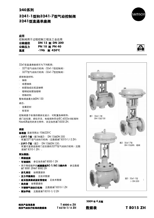
金属密封 · 软密封 · 高性能金属密封
等百分比 · 线性
DN 15到50为50:1、DN 65到150为30:1、DN 200及以上为50:1
PN25
PN16
温度范围(oC)· 允许操作压力按压力-温度图表(见信息表T 8000-2 ZH)
阀体没加延长段
-10 至 220 oC
延长段
阀体:
波纹管密 封
长
-
-196…450 oC
-
-196…300 oC
-
-196…450 oC
阀芯
标准 平衡
金属密封 软密封 PTFE密封 石墨密封
- 196…450 oC - 196…220 oC - 50…220 oC · 低温按需求提供 220…450 oC
泄漏等级按IEC 60534-4标准
阀芯
标准
金属密封 软密封
压差 允许的压差见信息表T 8000-4 ZH。
注 图4至图6为控制阀配置举例。
图5 · 3241型控制阀,锻钢类型 DN15至80、配置延长段
图6 · 3241型控制阀,锻钢类型 DN15至80、配置金属波纹管密封
图4 · 3241-1型控制阀 DN15至150 配置3271型气动执行机构
2
ቤተ መጻሕፍቲ ባይዱ
图7 · 3241型控制阀 DN 200至300
数据表 T 8015 ZH 2009 年 4 月版
% 5
表1 · 3241型技术数据
公称通径
DN
材料
公称压力 阀门连接
PN 法兰
端面焊接
阀座/阀芯密封
流量特性
可调比
加热套
最大到DN 100 ≥ DN 125
萨姆森气动调节阀的性能与调校
萨姆森气动调节阀的性能与调校摘要:调节阀是大家所熟悉的常用的控制仪表,在工业生产中起着非常重要的作用,其种类繁多。
本文结合自己的工作实践,介绍一种德国萨姆森公司生产的调节阀的性能和调试方法,为今后同类设备的施工提供借鉴作用,保证阀门的安装调试质量,确保工程的平稳运行。
关键词:萨姆森调节阀调校气动定位器1 前言萨姆森调节阀是德国SAMSON公司生产的高性能调节阀,适用于生产装置的自动控制,康派司公司设计的江阴聚酯工程中使用了大量的萨姆森气动调节阀(98台),在工程施工中,结合这种调节阀使用说明书的技术要求和以往施工经验,与常用电气阀门定位器的特点和原理进行比较,系统掌握这种先进调节阀的调试。
本文重点对这种调节阀的调试要求和调试注意事项进行总结。
2 调节阀结构与性能2.1 调节阀整体结构萨姆森的这款调节阀从总体结构上看其他调节阀没有太大区别,它是由阀体,执行机构及电/气阀门定位器组成,其采用模块化设计,可以方便的通过更换现有的执行机构,改变动作形式,并且可以将标准类型扩展成带隔离段或金属波纹管的类型,如果做为微流量调节阀,可以将常用的阀座-阀芯组合,用金属波纹管形所替代。
此款调节阀只有流开型,故障-安全动作分两种即执行器杆伸长、执行器杆收缩型,与国内调节阀说法虽有不同,但是功能相同,这里所谓的调节阀执行器杆伸长型,既当信号压力减少或供电故障时,压缩弹簧带动执行器杆向下移动,将阀门关闭。
当信号压力重新增加时,通过抵抗压缩弹簧力而使阀门打开(执行器杆伸长型用FA表示)。
执行器杆收缩型,既当信号压力减少或供电故障时,压缩弹簧带动执行器杆向上移动,将阀门打开。
当信号压力重新增加时,通过抵抗压缩弹簧力而使阀门关闭(执行器杆收缩型用FE表示)。
为了获得最大的定位力(阀门在全开,全关状态下),可以预调执行器上膜头弹簧预应力来达到,如0.02-0.1MPa的弹簧范围,可以调整为0.03-0.11MPa。
执行器杆伸长型,执行器杆收缩型,可以通过翻转上膜头组件来完成。
阿克萨科 F low Line 72 73 平板式蝶阀 2-24 型号 使用手册说明书

F low L ine 72/73Wafer &Lug StyleSizes 2 - 24Cartridge SeatedKEY FEATURESSeat/Disk/Shaft Sealing Method■The Flow Line shaft seal is achievedthrough a continuous pressure exerted from the flatted area of the seat to the machined flatted area of the disc.■The raised flatted area of the seat corresponds precisely with the machined flatted hub area of the disc. These matching flatted surfacesprovide a wide sealing area for the elastomer backed PTFE seat to exert pressure against,forming the primary seal.■Secondary sealing is provided by a 360ºmachined radius on the flatted hub.■This sealing mechanism is further enhanced by forces exerted on the seat to the 360ºradius on the disc providing a secondary shaft seal.■Both seals are made without the shaft ever coming in contact with the line media.■Two sets of elastomer seals are utilized to further assure no leakage to the outside environment. The first is two molded in o-rings in the shaft bore area of the seat. The second is an elastomer o-ring in theshaft to body area below the second bearing.Body■One piece wafer and lugged body for strength and stability in extreme environments ■Wafer bodies have a heavy external rib providing a quick and accurate alignment during installation.■Heavy duty top plate is drilled and slotted to ISO 5211 and other existing valve drillings, thus allowing ease of automation and interchangeability.■Standard extended neck provides full clearance for 2” of pipe insulation.■Two part polyester coated body provides a tough and durable coating against corrosion.Disc■All 316 stainless steel disc are polished to a mirror finish.■Discs have a streamlined design providing higher Cv and lower pressure drop.■The disc edge is contoured to give a tighter seal with lower torque.■Disc floats inside of the seat for a positive seal and extended seat life.Shaft■Oversized shafts allow for greater strength and thus more stability to the disc.■Two self lubricated bronze bearings aremachined to tolerances to the shaft and body eliminating side loading of the shaft. Thus preventing shaft leaks common to single bearing valves.■Blowout proof design is achieved byutilizing the shaft retainers to prevent any vertical movement.Disc/Shaft Connection■A high strength, machined Double “D”connection ensuress a positive shaft to disc connection.■Offset shaft retainers will not permit the shafts from moving up and down, thus preventing the jamming of the disc into the seat.Seat and Flange■Teflon and elastomer are both vulcanized to a rigid phenolic ring. This cartridge seat provides a stable platform eliminating movement of the PTFE and elastomer .■Torque fluctuation is eliminated because ofthe consistant conformity of the seat provided for by the cartridge design.■Large flange seal area assures no leakage when used with lined or unlined flangemating services. There is no need for gaskets or o-rings.■Cartridge design allows for full fieldENGINEERINGDIMENSIONSSPECIFICATIONSRecommended Specifications■Polyester coated wafer or lug bodies to provided extended necks for insulation and be able to install between ANSI 125/150 flanges.■Streamlined disc design with no pins or screws in the flow path and designed for high Cv and lowerpressure drop.■Upper and lower shaft design to utilize triple shaft seals as standard.■Blow out proof design utilizing a Double D drive fora positive disc/shaft connection.■Pressure responsive 360o sealing design will use constant pressure between machined radius on disc and flatted area of the seat.■Valve to be Flow Line Series 72 wafer or Flow Line Series 73 lug design.Materials of Construction2”-12”Body■Cast Iron ASTM A-126 Class B■Ductile Iron ASTM A-536 (65-45-12)■Ductile Iron ASTM A-395 (60-40-18)■316 Stainless Steel ASTM A351 (CF8M)■Carbon Steel 216 WCBDisc■M - Mirror Polish 316 Stainless SteelASTM A351 (CF8M)■K - Kynar Coated 316 Stainless Steel■H - Haylar Coated 316 Stainless Steel ■T - PTFE Coated 31655Stem■316 Stainless Steel ASTM A276T ype 316■416 Stainless Steel ASTM A582T ype 416Seat■T - PTFE / EPDM■V - PTFE / Viton®■ B - PTFE / Buna NViton is a registered trademark of the E.I. DuPont De Nemours Company. FKM is the ASTM D1418 designation for Flourinated Hydrocarbon elastomers such as Viton(DuPont) and Flourel(3M).COATINGSThe Series 72wafer style and Series 73lug style are heavy duty PTFE cartridgeseated butterfly valves. All Series 72 and 73 valves utilize a mirror polished 316 stainless steel disc. Kynar and Haylar coated 316 stainless steel disc are used in applications requiring the line media not to come into contact with organic or metallic materials.Series 72 and 73 PTFE lined valves are rated to 150 psi.TESTRESULTSalty Fog TestNo change in excess of 2000 hoursOutdoor Weathering (UV Rays)No noticeable change in excess of 12 months 50%Sulfuric Acid TestNo change for 48 hours■ISO 5211 shaft available for ease of actuation ■Slotted ISO 5211 top plate for flexibility ofdirect mounting options■Environmentalshaft seal to keep contaminants from entering shaft bore ■Offset shaft retainersmechanically retain the shaft ensuring a blow out proof design ■One piece Polyester coated body with extended neck ■Streamlined disc with no pins or screws in flow path■Two secondaryshaft seals located inside the seat shaft holestop and bottomFEATURES■High strength upper and lower shafts with triple shaft seals ■Two self lubricated bronze bearings to eliminate side loading ■Double D Drive for a positive disc/shaft connection with no pins or bolts exposed to flow■Proven pressure responsive 360osealing method uses constant pressure between machined radius on disc and flatted area of the seat that eliminates the “squeeze”of the interference seatdesign our competition relies on■PTFE,Elastomer,and Phenolic back arevulcanized together to form a rigid catridge ■Segmented Phenolic cartridge seat allows for pre compression of the PTFE seat face.Flow Line Series 70 and 71 butterfly valves bodies are Polyester coated as standard.Polyester is a significant upgrade to paint or two part epoxy coatings. Our standardPolyester coating offers outstanding protection against abrasion and corrosion. The Flow Line Polyester coating is not affected by outdoor exposure and maintains excellent resistance to UV rays.lever and bolt on plate notched at 10 degree increments.。
asco电磁阀327
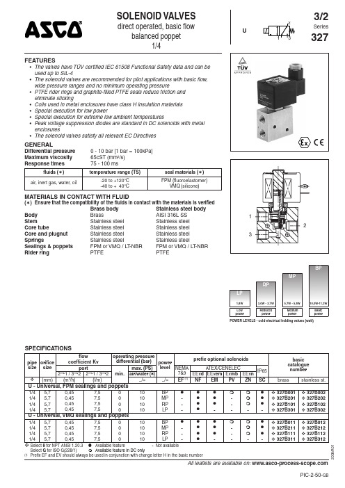
பைடு நூலகம்
U - Universal, FPM sealings and poppets
U - Universal, VMQ sealings and poppets
Select 8 for NPT ANSI 1.20.3
● Available feature - Not available Select G for ISO G(228/1) Available feature in DC only Prefix EF and EV should always be used in conjunction with change letter H in the basic number
fluids () air, inert gas, water, oil
MATERIALS IN CONTACT WITH FLUID
Body Stem Core tube Core and plugnut Springs Sealings & poppets Rider ring
All leaflets are available on: PIC-2-50-GB
SERIES 327
PREFIX TABLE
prefix power level description 1 2 3 4 5 6 7 LP RP MP BP S C D U Dustproof ATEX (EN 50281-1-1)* E F Explosionproof - NEMA 3, 4, 6, 7, 9 E V Explosionproof - NEMA 3, 4, 6, 7, 9 - 316 SS E M Encapsulated ATEX + IECEx (EN/IEC 60079 / 61241)* E T Threaded conduit/hole (M20 x 1.5) I S S C Intrinsically safe with SC coil ATEX (EN 50020)* N F Flameproof - Aluminium ATEX (EN 50018)* P V - Encapsulated ATEX + IECEx (EN/IEC 60079 / 61241)* S C Solenoid with spade plug connector (EN 60730) W P Waterproof IP67 - Metal enclosure (EN 60730) W P D U Dustproof ATEX (EN 50281-1-1) - Metal enclosure* W P I S I.S. with Metal IP67 enclosure ATEX (EN 50020)* W P Z N Non Sparking metal enclosure ATEX (EN 50021)* W S Waterproof IP67 - 316 SS enclosure W S D U Dustproof ATEX (EN 50281-1-1) - 316 SS enclosure* W S E M 316 SS "EM" encl. ATEX + IECEx (EN/IEC 60079/61241)* W S I S I.S. with 316 SS IP67 enclosure ATEX (EN 50020)* W S N F Flameproof - 316 SS ATEX (EN 50018)* W S Z N Non Sparking 316 SS enclosure ATEX (EN 50021)* T Threaded conduit (1/2" NPT) H C Class H - Battery charging circuit H T Class H - High temperature Z N - Encapsulated Non Sparking ATEX (EN 50021)* X Other special constructions
气动执行机构
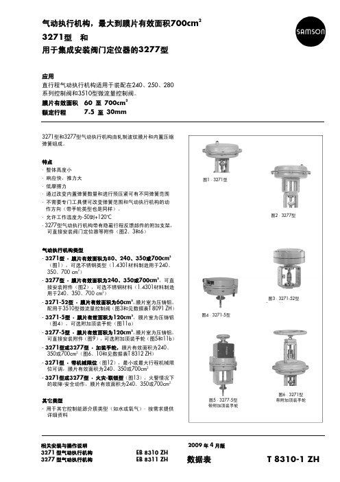
气动执行机构,最大到膜片有效面积700cm2 3271型和用于集成安装阀门定位器的3277型应用直行程气动执行机构适用于装配在240、250、280系列控制阀和3510型微流量控制阀。
膜片有效面积 60 至 700cm2额定行程7.5 至 30mm3271型和3277型气动执行机构由轧制波纹膜片和内置压缩弹簧组成。
特点· 整体高度小· 响应快,推力大· 低摩擦力· 通过改变内置弹簧数量和进行预压紧可有不同弹簧范围· 不需要专门工具便可改变弹簧范围和气动执行机构的动作方向(带手轮类型也是同样)。
· 允许工作温度为-50到+120o C· 3277型气动执行机构带有隐蔽行程反馈部件的附加支架,可直接安装阀门定位器等附件(图2、3和6)气动执行机构类型- 3271型 · 膜片有效面积为80、240、350或700cm2(图1),可选不锈钢类型(1.4301材料制造用于240、350、700cm2)- 3277型 · 膜片有效面积为240、350或700cm2,可直接安装附件(图2),可选不锈钢材料(1.4301材料制造用于240、350、700cm2)- 3271-52型 · 膜片有效面积为60cm2,膜片室为压铸铝,配用于3510型微流量控制阀(图3和见数据表T 8091 ZH)- 3271-5型 · 膜片有效面积为120cm2,膜片室为压铸铝(图4),可选附加顶装手轮(图11a)- 3277-5型 · 膜片有效面积为120cm2,膜片室为压铸铝,可直接安装附件(图9),可选附加顶装手轮(图5和11b)- 3271型或3277型 · 加装手轮,膜片有效面积为240、350或700cm2(图6、10和见数据表T 8312 ZH)- 3271型 · 带机械限位(图12),最小或最大行程机械限位可调,膜片有效面积为240、350或700cm2- 3271型或3277型 · 火灾-联锁型(图13),火警情况下的故障-安全动作,膜片有效面积为240、350或700cm2其它类型- 用于其它控制能源介质类型(如水或氧气)· 按需求提供详细资料图1·3271型图2 · 3277型图4 ·3271-5型图3 · 3271-52型图5 ·3277-5型带附加顶装手轮图6 ·3271型带附加顶装手轮相关安装与操作说明 2009年4月版3271型气动执行机构 EB 8310 ZH3277型气动执行机构 EB 8311 ZH 数据表T 8310-1 ZH工作原理信号压力pst 作用在气动执行机构的膜片有效面积A (2)上,产生推力F = pst x A 。
SAMSON_3277_Operation_Manual_EN

Pneumatic ActuatorType 3277Fig.1· Type 3277 Pneumatic Actuator2· Type 3277-5 Pneumatic ActuatorMounting andOperating InstructionsEB8311 ENJuly 20061Design and principle ofoperationThe Type 3277Pneumatic Actuators with an effective diaphragm area of 240, 350 or 700 cm² are primarily mounted to control valves from the Series 240, 250 and 280.Type 3277-5 with a die-cast aluminum case and an effective diaphragm area of120 cm², is mounted to Type 3510 and Se-ries 240 Valves.The actuator is made up of two diaphragm cases, a rolling diaphragm and springs. The lower diaphragm case is permanently fixed to the yoke which allows the direct attach-ment of either a pneumatic or electropneu-matic positioner or a limit switch.Actuators with manual override (Fig. 5) ad-ditionally have a handwheel mounted on the diaphragm case. The handwheel moves theactuator stem over a spindle after the lock-ing mechanism (lock nut) has been disen-gaged. In addition, the actuator can be equipped in a special version with a me-chanically adjustable travel stop.The signal pressure creates a force at the di-aphragm surface which is balanced by the springs (6) arranged in the actuator. The number of springs and their compression determine the bench range (signal pressure range) while taking the rated travel into ac-count which is directly proportional to the signal pressure. A maximum of 30 springs can be installed, partly fitted inside one an-other.The stem connector (16) connects the actua-tor stem (2) with the plug stem of the control valve.2EB 8311ENDesign and principle of operationFail-safe actionWhen the signal pressure fails, the fail-safe action of the actuator depends on whether the springs are installed in the top or bottom diaphragm chamber.Actuator stem extendsWhen the signal pressure is reduced or the air supply fails, the springs move the actua-tor stem downwards and close the valve. The valve opens when the signal pressure is increased enough to overcome the force ex-erted by the springs.Actuator stem retractsWhen the signal pressure is reduced or the air supply fails, the springs move the actua-tor stem upwards and open the valve. The valve closes when the signal pressure is in-creased enough to overcome the force ex-erted by the springs.EB8311EN3Design and principle of operationLoading pressure connectionType 3277 Actuator(Fig. 3)In the Type 3277 Actuator with fail-safe ac-tion "Actuator stem extends", the loading pressure is connected to the loading pres-sure connection (11) at the side of the yoke to fill the bottom diaphragm chamber which causes the actuator stem (2) to move up-wards. In an actuator with the fail-safe ac-tion "Actuator stem retracts", the loading pressure is connected the loading pressure connection (4) to fill the top diaphragm chamber which causes the actuator stem to move downwards.Type 3277-5 Actuator(Fig. 4)In the Type 3277-5 Actuator, the loading pressure is connected to a borehole either at the left or right of the yoke. A switchover plate(14, accessories) directs the air to one of the diaphragm chambers, depending on the fail-safe action of the actuator ("Actuator stem extends" or "Actuator stem retracts"), which is determined by how the plate is aligned with the mark (14.4).4Turn the switchover plate to align the symbol (14.3) for the appropriatefail-safe action with the mark (14.4). SeeFig. 4, bottom left. The operating direc-tion (>>) or (<>) of the positioner deter-mines whether the left or right attach-ment is to be used.A connecting plate(accessories) is required instead of the switchover plate if the actua-tor is operated without a positioner. The loading pressure is directly connected to the loading pressure connection (14.8) of the connecting plate to fill the diaphragm cham-ber.4Turn the connecting plate to align the symbol (14.3) for the appropriatefail-safe action "Actuator stem extends"or "Actuator stem retracts" with the mark(14.4). See Fig. 4, bottom right.4Make sure that the flat gasket of the con-necting plate is correctly inserted.4The connecting plate has both NPT andG threaded bores. Seal the bore not re-quired with a rubber gasket and squareplug.Accessories:The switchover plate or con-necting plate must be ordered separately. Please note that actuators with modification index01e.g. 3277-531xxx20.01(old =.00) are equipped with new plates.Old and new plates are not interchangeable.Note!The pneumatic actuators are designed for a maximum supply pressure of 6 bar. To prevent the actuator from being dam-aged, do not let the supply pressure exceed the upper spring range value by more than 3 bar when the actuator is used forflow-switching service (on-off valve) with the fail-safe position "Actuator stem retracts". Label actuators that have a reduced supply pressure with a sticker "max. supply pres-sure limited to … bar".Note!Refer to the operating instructions of the corresponding valve on how to mount and remove the actuator from the valve.4EB8311ENDesign and principle of operationDesign and principle of operationEB8311EN52Operation Note!It is important for a trouble-free operation of the Type 3277 Actuator that the vent plug (3) is not blocked.Make sure in versions with a handwheel that the plug stem can move freely when the valve is being positioned by the pneumatic actuator by moving the handwheel into a neutral position.2.1Reversing the operating direction (fail-safe action)The operating direction, i.e. fail-safe action,of pneumatic actuators can be changed.Prior to proceeding, you must remove the actuator from the valve.The fail-safe action is represented by a sym-bol on the nameplate."Actuator stem extends""Actuator stem retracts"2.1.1Standard actuatorReversing the fail-safe action "Actuator stem extends" to "Actuator stem retracts"Note!Actuators with 700 cm² (travel = 30 mm)that are mounted to valves with 15 mm travel, are preloaded by approx. 75 % on mounting them to the valve.The signal pressure range is recorded on the nameplate when the actuators have been preloaded on mounting them to the valve.1.Unthread nuts and remove the bolts (9)from the diaphragm cases.2.Lift off the top diaphragm case (5) andremove the springs (6).3.Pull the actuator stem (2) with dia-phragm plate (7) and diaphragm (8) out of the yoke (10).4.Unscrew nut (1), while holding the nut(1.1) stationary or clamping the actuator stem with a suitable tool.Caution!Proceed carefully to avoid damaging the seals of the actuator stem.6EB 8311ENOperationCaution!Do not loosen the nut (1.1) on the actuator stem. It is painted over to protect it.If, however, it has been loosened, it is essen-tial that the dimension a(Figs. 3 and 4) measured from the top of the nut to the bot-tom of the actuator stem is kept.5.Apply lubricant/sealant (order no.8152-0043) to the sealing places on the actuator stem.6.Turn over top diaphragm case (5). Placethe actuator stem with diaphragm plate,diaphragm and metal plate (7.1), if ap-plicable in the case.7.Insert the springs (6) and slide the yokewith bottom diaphragm case over theactuator stem.8.Screw tight the nuts and bolts of the dia-phragm cases. Remove vent plug (3) inType 3277 Actuator.Proceed in the same manner for theType 3277-5Actuator intended for the mi-cro-valve, but additionally attach the bush-ing (2.1) for the mechanical travel stop. The springs now press from below against the diaphragm plate and cause the actuator stem to retract (fail-safe action). The actuator stem only starts to extend when the signal pressure overcomes the force of the springs.9.Record the changed fail-safe action onthe nameplate!Reversing the fail-safe action "Actuator stem retracts" to "Actuator stem extends"1.Unthread nuts and remove the bolts (9)and lift off the top diaphragm case (5).2.Pull the actuator stem with diaphragmplate, diaphragm and metal plate (7.1),if applicablethe diaphragm plate (7) outof the yoke and bottom diaphragm case(10).3.Unscrew nut (1), while holding the nut(1.1) stationary or clamping the actuatorstem with a suitable tool.Caution!Proceed carefully to avoiddamaging the seals of the actuator stem.4.Remove the diaphragm plate with dia-phragm and replace them in reverse or-der. Screw tight nut (1).5.Coat the sealing parts of the actuatorstem with sealant/lubricant (order no.8152-0043).6.Insert the actuator stem with diaphragmplate, diaphragm and metal plate (7.1),if applicable, into the bottom diaphragmcase with yoke.7.Insert springs (6) and place the top dia-phragm case back on. Screw tight thenuts and bolts of the diaphragm cases.8.Screw the vent plug (3) into the top load-ing pressure connection of theType 3277 Actuator.Proceed in the same manner for theType 3277-5Actuator intended for the mi-cro-valve, but additionally attach the bush-ing (2.1) for mechanical travel stop.The springs now press from the top against the diaphragm plate and cause the actuator stem to extend (fail-safe action). The actua-EB8311EN7 Reversing the operating direction(fail-safe action)tor stem only starts to retract when the signal pressure overcomes the force of the springs.9.Record the changed fail-safe action onthe nameplate!2.1.2Actuator with handwheel Type 3277(Fig. 5) only1.Undo lock nut (20) and relieve thesprings (6) by turning the handwheel(17).2.Loosen threaded pin (26) and unscrewcoupling nut (25) from the coupling(22).3.Knock out the clamping sleeve (23) andremove the ring (24).4.Unthread the ring nut (15) and lift off theflange part (21) together with the cou-pling nut (25).Reversing the fail-safe action "Actuator stem extends" to "Actuator stem retracts" 4Proceed as described in section 2.1.1.However, use the word "spindle with nut(27)" in place of "nut (1)".After reversing the operating direction:1.Replace the flange part (21) with ringnut (15) and coupling nut (25).2.Tighten ring nut (15). Attach the ring(24) with clamping sleeve (23).3.Screw coupling nut (25) as far as it willgo onto the coupling (22) and securewith threaded pins (26).Reversing the fail-safe action "Actuator stem retracts" to "Actuator stem extends" 4Proceed as described in section 2.1.1.However, use the word "spindle with nut(27)" in place of "nut (1)".After reversing the operating direction:1.Replace the flange part (21) with ringnut (15) and coupling nut (25).2.Tighten ring nut (15). Attach the ring(24) with clamping sleeve (23). Attachthe ring (24) with clamping sleeve (23).3.Screw coupling nut (25) as far as it willgo onto the coupling (22) and securewith threaded pins (26).8EB8311ENReversing the operating direction(fail-safe action)Reversing the operating direction(fail-safe action)EB8311EN92.2Adjusting the travel stop(with Type 3277 in special version only)The travel stop can be adjusted upwards or downwards to 50% of the travel.Downward travel stop (actuator stem extends)1.Undo the lock nut (34) and unscrew thecap (33).2.Undo the lock nut (31) and adjust thenut (32) to set required travel stop.3.Tighten the lock nut (31) again.Upward travel stop (actuator stem retracts)1.Undo the lock nut (34) and adjust thecap (33) to set the required travel stop.2.Tighten the lock nut (34) again.10EB 8311ENAdjusting the travel stopFig.6· Travel stop333132345722Actuator stem5Top diaphragm case 7Diaphragm plate 31Lock nut 32Nut 33Cap 34Lock nutActuator stem extendsActuator stem retracts3Replacing the diaphragm and stem seal3.1Diaphragm(Fig. 3)1.Remove the diaphragm plate (7) to-gether with diaphragm (8) and actuatorstem (2) from the diaphragm case as de-scribed in section 2.1.1.2.Remove the hose clamp and pull it to-gether with the diaphragm (8) off the di-aphragm plate (7) (not necessary withType 3277-5 as the diaphragm is heldin place by the metal plate (7.1)).3.Stretch the new diaphragm onto the dia-phragm plate. Fit the hose clamp evenlyinto the groove intended for it andtighten.4.Reassemble actuator as described insection 2.1.1.3.2Stem seal1.Remove the diaphragm plate (7) to-gether with the actuator stem (2) fromthe diaphragm case as described insection 2.1.1.2.Coat the new stem seal (12) with lubri-cant/sealant (order no. 8152-0043)and insert it.3.If necessary, replace the dry bearing(12.1) and wiper (13) with new ones aswell.4.Reassemble the actuator as described insection 2.1.1.4Customer inquiriesPlease specify the following details on mak-ing inquires:4Type and model number4Effective diaphragm area4Bench range (spring range) in bar4Actuator version and its operating direc-tionDimensions and weightsRefer to the Data Sheet T 8310-1 EN dimen-sions and weights of the different actuator versions.EB8311EN11 Replacing the diaphragm and stem sealSAMSON AG · MESS- UND REGELTECHNIKWeismüllerstraße 3 ·60314 Frankfurt am Main ·Germany Phone: +49 69 4009-0 ·Fax: +49 69 4009-1507Internet:http://www.samson.deEB 8311 ENS /Z 2006-08。
samson控制阀选型手册

9
电磁阀
21
3254 型直通单座控制阀
9
闭锁阀
21
3256 型角型控制阀
10
气动遥控器
21
3259 型角型控制阀
10
空气减压阀
21
W&T RVG 型控制阀
10
空气过滤减压阀
21
衬里单座控制阀
气动继动器
21
Pfeiffer BR 1a 型带 PTEE 衬里
10
Pfeiffer BR 1b 型带 PFA 衬里
•
• •
• • •
3244 8026
•
• •
3248
8093 •
• • •
15... 150
½… 6
16,40
• 15... 150
½… 6
16,40
150 , 150,
300
300
见相关数据表 •
• •
•
•
351CF8
•
•
•
•
•
•
•
•
•
•
•
•
• • •
3249 8048
• • •
• 15... 80
•
½… 8
150... 2500
•
•
•
15... 25 ½… 1
40… 400
300... 2500
8055 •
8060 •
•
•
15... 400 ½… 12
10… 160
150... 2500
•
80... 500
16… 400
•
•
•
•
•
•
samson 3241-1型和3241-7型气动控制阀 安装与操作说明

气动控制阀3241-1型和3241-7型安装与 操作说明EB 8015 ZH图1 · 配3271型和3277型执行机构的3241型气动控制阀 3241-1型3241-7型2007年7月版目录目录页1 结构和工作原理‥‥‥‥‥‥‥‥‥‥‥‥‥‥‥‥‥ 42 装配阀门和执行机构‥‥‥‥‥‥‥‥‥‥‥‥‥‥‥ 42.1 装配和调整‥‥‥‥‥‥‥‥‥‥‥‥‥‥‥‥‥‥‥ 42.2 “执行机构推杆伸出”类型执行机构的预紧弹簧‥‥‥72.3阀门和不同行程范围的执行机构‥‥‥‥‥‥‥‥‥‥83 安装‥‥‥‥‥‥‥‥‥‥‥‥‥‥‥‥‥‥‥‥‥‥93.1安装位置‥‥‥‥‥‥‥‥‥‥‥‥‥‥‥‥‥‥‥‥93.2信号压力管线‥‥‥‥‥‥‥‥‥‥‥‥‥‥‥‥‥‥93.3过滤器、旁路‥‥‥‥‥‥‥‥‥‥‥‥‥‥‥‥‥‥93.4 测试连接‥‥‥‥‥‥‥‥‥‥‥‥‥‥‥‥‥‥‥‥94操作‥‥‥‥‥‥‥‥‥‥‥‥‥‥‥‥‥‥‥‥‥‥95 维修-更换部件‥‥‥‥‥‥‥‥‥‥‥‥‥‥‥‥‥‥105.1标准型阀门‥‥‥‥‥‥‥‥‥‥‥‥‥‥‥‥‥‥‥115.1.1 填料函填料‥‥‥‥‥‥‥‥‥‥‥‥‥‥‥‥‥‥‥115.1.2 阀座和/或阀芯‥‥‥‥‥‥‥‥‥‥‥‥‥‥‥‥125.2 带延长段或金属波纹管密封的阀门‥‥‥‥‥‥‥‥‥135.2.1 填料函填料‥‥‥‥‥‥‥‥‥‥‥‥‥‥‥‥‥‥‥135.2.2 阀芯‥‥‥‥‥‥‥‥‥‥‥‥‥‥‥‥‥‥‥‥‥‥135.2.3 阀座‥‥‥‥‥‥‥‥‥‥‥‥‥‥‥‥‥‥‥‥‥‥155.2.4 金属波纹管‥‥‥‥‥‥‥‥‥‥‥‥‥‥‥‥‥‥‥155.2.5 重新组装‥‥‥‥‥‥‥‥‥‥‥‥‥‥‥‥‥‥‥‥165.3 更换平衡阀芯衬圈或密封‥‥‥‥‥‥‥‥‥‥‥‥‥166材料识别标志‥‥‥‥‥‥‥‥‥‥‥‥‥‥‥‥‥‥187 铭牌说明‥‥‥‥‥‥‥‥‥‥‥‥‥‥‥‥‥‥‥‥198 用户咨询‥‥‥‥‥‥‥‥‥‥‥‥‥‥‥‥‥‥‥‥19此《安装与操作说明》也可配合T 8046-1 ZH数据表,适用于3246型单座阀(Class 150和300)。
- 1、下载文档前请自行甄别文档内容的完整性,平台不提供额外的编辑、内容补充、找答案等附加服务。
- 2、"仅部分预览"的文档,不可在线预览部分如存在完整性等问题,可反馈申请退款(可完整预览的文档不适用该条件!)。
- 3、如文档侵犯您的权益,请联系客服反馈,我们会尽快为您处理(人工客服工作时间:9:00-18:30)。
气动执行器可有下列故障-安全动作位置: “气动执行器杆伸出(FA)”: 当作用在膜片上的信号压力减少或气源故障,膜片室内的弹簧 力使气动执行器杆“伸出”到最下端位置 (在后面的剖面图中 的右半部图示)。 “气动执行器杆缩回(FE)”: 当作用在膜片上的信号压力减少或气源故障,膜片室内的弹簧 力使气动执行器杆“缩回” (在后面的剖面图中的左半部图 示)。
相关安装和操作说明 3271型气动执行器 3277型气动执行器
EB 8310 ZH EB 8311 ZH
ห้องสมุดไป่ตู้
2005年4月版
数据表
T 8310-1 ZH
工作原理 信号压力pst作用在气动执行器膜片面积A(2)上,产生推力 F = pst•A 。这个力推动膜片/执行器杆位移和压缩内置弹簧 (4),并与弹簧力相平衡。内置弹簧的数量和对其预压紧决 定着气动执行器工作范围和额定行程。气动执行器行程H与所 加信号压力pst成正比。执行器杆(7)的动作方向取决于内置 弹簧装配位置和信号压力连接位置(1)。 用杆连接器(8)可把气动执行器杆(7)与控制阀的阀杆(10) 连接起来。 图10所示可调整的机械限位,适用在有效膜片面积240、350和 700cm2及膜片室为钢板材料的气动执行器。使用机械限位可在 两个方向上(执行器杆“伸出”或“缩回”)限制气动执行器 的行程,限位停止位置可达到行程的50%并连续可调。还有在 有效膜片面积120cm2气动执行器的一侧加装机械限位的特殊 型。
特点 - 整体精小型化, - 响应快,推力大 - 摩擦力小。 - 通过改变内置的压缩弹簧数量和预压紧可调整为不同工作
范围。 - 不需要专门工具便可改变工作范围和气动执行器动作方向 (带手轮气动执行器也是同样)。 - 设计气源压力最大为6巴 - 可在-35到+90℃环境温度下连续工作。 - 3277型气动执行器设计有执行器支架,可直接安装阀门定位
执行器加装手轮(图6和见数据表T 8312 ZH) - 3271型·带机械限位(剖面图12),有效膜片面积为240、
350,700cm2 - 3271型或3277型·火警联锁型(图13),火警时故障-安全
动作,有效膜片面积为240、350,700cm2
特殊型 - 根据需要,可提供使用气源之外的其他控制能源介质(如水、
表1a 3271型气动执行器技术数据
类型
3271型
3271型 不锈钢
3277型
3277型 不锈钢
3271-52型 (用于微流量
阀)
3271-5型 3277-5型
有效膜片面积
cm2
80、240、350、700
240、350、700
60
120
最大气源压力
6巴·(参见第6页的在快速全开/关操作中的限制)
连续工作时允许温度
图9 3277-5型气动执行器 用于直接安装附件
图7 3271型(图中右半部所示带有套装的附加压缩弹簧) 图7 3277型用于直接安装附件
图10 3277型气动执行器 带顶装手轮
图例 1 信号压力接口 2 膜片 3 排气孔 4 气动执行器压缩弹簧 5 膜片室 6 锁紧螺母 7 气动执行器杆 8 杆连接器 9 联结螺母 10 阀杆
气动执行器·最大有效膜片面积700cm2 3271型 3277型·阀门定位器直接安装设计
应用 装配在终端控制元件上的直行程气动执行器,适用于240、250、280系列控制阀 和3510型微流量控制阀。 有效膜片面积从60到700cm2 额定行程从7.5到30mm
3271型和3277型气动执行器是膜片式执行器,配有轧制波纹膜 片和内置压缩弹簧,
油或氧气)的气动执行器。 - 根据需要,可提供适应最高温度达120℃的气动执行器 - 根据需要,可提供适应最低温度达-40℃的气动执行器
图1 3271型气动执行器
图2 3277型气动执行器
图3 3271-52型气动执行器
图4 3271-5型气动执行器
图5 3271-5型气动执行器 带顶装手轮
图6 3271型气动执行器 带顶装手轮
材料 膜片 气动执行器杆 执行器杆密封
标准材料NBR:-35至+90℃ 特殊材料EPDM(用于无油无油脂的空气):-40至+120℃, 适用240、350、700cm²气动执行器 火警联锁型(240、350、700cm²):最高80℃
NBR(丁腈橡胶)加纤维 EPDM加纤维 1.4305 NBR EPDM
于3510型微流量控制阀(图3和见数据表T 8091 ZH) - 3271-5型·有效膜片面积为120cm2,膜片室为压铸铝(图4),
可选附加顶装手轮(图11a) - 3277-5型·有效膜片面积为120cm2,膜片室为压铸铝(图4),
可直接安装附件(图9),可选附加顶装手轮(图5和11b) - 3271型或3277型·有效膜片面积为240、350,700cm2的气动
3271型 3277型 240、350、700 cm² (仅用于初始弹簧值≤2.1巴) St37-2 喷漆 不锈钢1.4104
铝
3
T 8310-1 ZH 2005年4月版
有效膜片面积[cm²] 额定行程[mm] 额定行程时容积[dm3] 不使用容积[dm³] 最大行程[mm]1)2) 工作范围[巴] (额定行程内信号压力范围) 附加的弹簧压缩[%] 弹簧预压紧的工作范围[巴] 弹簧数量 0mm行程的弹簧力[kN]1 ) 额定行程的弹簧力[kN]
器等附件和隐蔽行程反馈部件
类型 - 3271型·有效膜片面积为80、240、350,700cm2(图1),
可选不锈钢材料(1.4301) - 3277型·有效膜片面积为240、350,700cm2,可直接安装附
件(图2),可选不锈钢材料(1.4301) - 3271-52型·有效膜片面积为60cm2,膜片室为压铸铝,配用
表2 气动执行器(最大700cm2)工作范围(弹簧范围)
额定行程和气源压力时的 公称推力〔Kn〕
1.4 2巴 3巴 4巴 5巴 6巴 巴
用于3510型微流量控制阀
1) 在工作范围下限,考虑到零行程(阀芯动作起点)。 2) 在故障-安全动作位置,如表3中的零行程。 3) 预压紧弹簧。 4) 不能用在带手轮的类型上
-35至+80℃ -35至+90℃
NBR
1.4305/1.4571
1.4305
NBR
NBR
膜片室
钢板 喷漆
不锈钢 1.4301
钢板 喷漆
不锈钢 1.4301
压铸铝 喷漆
表1b 附加手轮技术数据 执行器类型
有效膜片面积
材料
本体 轴 手轮
3271-5型 3277-5型
120 cm²
压铸铝 喷漆 1.4305 铝 喷漆
11 支架 12 至手轮的执行器杆 14 盖帽 15 螺母 16 杆 17 止挡轴套 18 锁紧螺母 23 手轮
2
T 8310-1 ZH 2005年4月版
图12 3271型带可调整机械限位
图11a、11b 3271-5和3277-5型 故障-安全动作“杆伸出” 带顶装手轮
图13 火警联锁型 右图所示在故障-安全位置
4
T 8310-1 ZH 2005年4月版
图14 3271-5型
图14a 3271-5/3277-5型 7.5mm行程,用于3510型 微流量控制阀
图15 3277-5型附加顶装手轮
图16 3271型(700cm2带吊环)
图17 3277型(700cm2带吊环)
图18 3271型附加顶装手轮
5
图19 3277型附加顶装手轮
