VICSEN-PUL全自动润滑脂加注器
威盾科技电动油脂润滑泵说明书
威盾科技电动油脂润滑泵说明书引言:威盾科技电动油脂润滑泵是一种高效、便捷的润滑设备,广泛应用于工业制造、机械设备维护等领域。
本说明书将为用户提供电动油脂润滑泵的详细介绍、操作说明和维护要点,以帮助用户正确使用和保养该设备,以确保其正常运行并延长使用寿命。
一、产品概述威盾科技电动油脂润滑泵是一种自动化设备,采用电动机驱动,用于将油脂输送至机械设备的润滑点,以实现设备的良好润滑和运行。
该泵具有体积小、重量轻、操作简便等特点,适用于各种工业设备的润滑需求。
二、产品特点1.高效节能:威盾科技电动油脂润滑泵采用高效电动机驱动,具有能耗低、效率高的特点,可有效节省能源消耗。
2.可调控性强:该润滑泵可根据设备的润滑需求进行调节,包括油脂输送量、压力等参数的调整,以满足不同设备的需求。
3.安全可靠:威盾科技电动油脂润滑泵具有过载保护装置,在运行过程中能自动监测电流,一旦超过额定电流,泵会自动停止工作,以保护设备安全。
4.维护简便:该润滑泵采用模块化设计,易于拆卸和维护,可大幅减少设备的维修和维护成本。
三、操作说明1.安装:首先,将润滑泵安装在固定的基座上,并确保泵的稳定性。
接着,根据设备的润滑需求,选择合适的润滑脂,并将其加入润滑泵的油脂储罐中。
2.接通电源:将电源线插入电源插座,并确保电源线连接牢固,接通电源后,润滑泵即可开始工作。
3.调节参数:根据设备的润滑需求,通过润滑泵上的控制面板,调节泵的工作参数,包括油脂输送量、压力等参数,确保润滑效果最佳。
4.运行监测:在使用过程中,用户应定期检查润滑泵的运行状态,确保其正常工作。
如发现异常情况,应立即停止使用,并进行维护处理。
5.停止使用:当设备润滑完成或需要停止使用时,应将润滑泵断开电源,并进行相应的维护清洁工作。
四、维护要点1.定期检查:用户应定期检查润滑泵的油脂储罐,确保油脂充足,并及时清理油脂储罐的杂质。
2.润滑脂更换:根据使用情况,定期更换润滑脂,以保证润滑效果。
Pulsarlube E 自动加脂器说明书
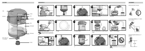
将外壳盖拧在阀体上喷脂结束后请取出加脂器用螺丝刀 (-) 取出PCB线路板取出电池盒按照所需周期插入模式选择片(例; 3个月)拧开螺丝并打开电池盖产品平面图打开机盖电池盒电池活塞PCB线路板底部 (Base)氮气储存箱防护盖螺纹/外螺纹 1/4"可以互换使用1标贴上标注安装日期与止喷日期并安装于润滑点本产品为可拆解环保型产品, 为拆解产品请先打开机盖从默认关闭位置取出黄色模式选择器2最后处理加脂器机身Note产品作废时请勿在产品上钻孔或重复使用本产品3971210111413如产品安装部位重量超过1公斤, 请使用1/4"以上的径头。远程安装时连接管长度请保持1m以下(Ø8基准)如背压过高会导致不正常出脂。安装注意事项备注擦干油脂嘴周边的污垢拧开油脂嘴 (Nipple) 接合相应变径接头如管路被堵请用黄油枪打通管路Note1 如油脂硬化请用黄油枪清除 (Purging) 硬化油Note2 油脂需要与目前使用的油脂相同或具有相容性Pulsarlube E 标准油脂产品认证认证书1个月 2.00ml/日 4.00ml/日 8.00ml/日 3个月 0.67ml/日 1.33ml/日 2.66ml/日 6个月 0.33ml/日 0.67ml/日 1.33ml/日 9个月 0.22ml/日 0.44ml/日 0.89ml/日12个月0.17ml/日0.33ml/日0.67ml/日每日加脂量日供油量(ml/day)是由加脂器使用条件1气压20摄氏度为基准算出的结果。 根据周边环境, 温度, 气压, 油脂的粘度, 连接管的背压加注含量也将不等。质保期每个自动加脂器的保质期为一年。产品质保仅限于材料以及工艺的原始缺陷, 不包括任何由于误操作, 滥用以及任何其他不合理使用该产品而产生的附带损害。备注PL1 多效脂 高效多用途 (MP) PL2 重荷脂 含固体润滑粒高效耐压(EP) PL3 高速脂 适用于3,000rpm以上 / 适合DN使用PL4食品脂 NSF H1等级 食品专用 PL5 高温脂 较好的耐磨性能 PL6 多效脂 (含MoS2)提高耐压性(EP) / 多用途 (MP) PL7 低温脂 '适用于'-15℃以下低温环境IEC 60079-0:2011IEC 60079-11:2011Approval No. 18-A180003-0TESTED FOR INTRINSIC SAFETY IN METHANE -AIR MIXTURES ONL Y。
simalube 自动润滑油器产品说明书

simalubeAdvantages of automatic lubrication with simalube 3simalube – the lubrication expert 4/5simalube 15 ml 6simalube multipoint 7simalube IMPULSE 8/9Applications 10/11Standard lubricants 12Accessories 13/14/15simalube: continuouslubrication ensures low costsand high reliabilityMillions of simalube lubricators are used worldwide in everyindustry. They are the best and most economical solution forthe continuous supply of grease or oil for periods of up to oneyear.simalube – everywhere forces act, something spins orsomething moves.Because my bearingsare worth it!«Once installed, simalube lubricators lubricateevenly, accurately and reliably. This is not at allpossible with manual lubrication.»23Advantages of automatic lubrication with simalubeOptimized lubricant delivery Lower costs thanks to simalubesimalube lubricators replace costly manual lubrication. This not only saves time, but also prevents insufficient or over-lubrication. The costs can thus be reduced by up to 30 percent.No more manual lubrication ■ Saves time■Greater work safety■ Hard-to-reach lubrication points are permanently supplied ■ Lower lubricant consumptionNo under- or over-lubrication of components ■ Less wear■ Less machine downtime■ Increased machine performanceSealed, dustproof and waterproof system ■ No more confusion of lubricants ■ Reduced risk of contamination■ No contamination of lubrication pointsCompliance with international standards ■ TÜV-tested and Ex certified in all zones ■ Improved workplace safety■ No environmental impact thanks to recycling and disposal according to regulationsContinuous lubricant delivery with simalube effectively prevents insufficient or over-lubrication that often occurs with manual lubrication.Up to 30 percent lower costs:■ Time-saving and greater safety at work thanks to fewer maintenance intervals■ Longer machine service life and less unplanned down-timesimalube – the automatic single-point lubricatorAvailable in 5 sizes, simalube supplies various lubrication points with lubricant around the clock.Day in, day out – for up to one year.simalube –the lubrication expertMore technical information and user manual can be downloaded at /en/simalubeTOM'sTIPReliability■ Lubrication points are continuously supplied with lubricant ■ No lubrication point is missed■ Easy monitoring of the dispensing process thanks to the transparent housingEnvironmental sustainability■ simalube can be refilled up to 3 times ■ Easy disposal at end of dispensing cycle■ simalube lubricators do not contain toxic substancesFlexibility■ simalube is available in 5 sizes: 15, 30, 60, 125 and 250 ml ■ Freely selectable dispensing cycle of 1 to 12 months ■ Dispensing cycle can be modified anytime■ simalube is available filled or empty for self-fillingUnlimited range of uses (see pages 10/11)To determine the size and time setting, use our free«Calculation Pro» program at /en/calproProductAutomatic long-term grease and o il lubricator Power generation Hydrogen gas producing drycell Working pressure Max. 5 barAdjustment Stepless 1–12 months(for standard conditions)Operating temperature – 20 °C to +55 °C ambient temperature(Grease consistency changes with temperature)Storage temperatureRecommended at 20 °C ±5 °C Lubricator volume 30 ml 60 ml 125 ml 250 ml Weight full ~82 g ~115 g ~190 g ~335 g Weight empty ~55 g~60 g~75 g~111 gRefill The 15–250 ml simalubes are r efillable.CertificationsComponents Specifications43 m m (1.7 i n )sima lube 3062 m m (2.4 i n )sima lube 60100 m m (3.9 i n )sima lube 12514 m m (0.55 i n )14 m m (0.55 i n )14 m m (0.55 i n )14 m m (0.55 i n )193 m m (7.6 i n )sima lube 250DrivePistonØ 52 mm Ø 52 mmØ 52 mm Ø 52 mmG 1/4"G 1/4"G 1/4"G 1/4"6simalube 15 mlProduct Automatic, long-term grease andoil lubricatorPower generation Hydrogen gas producing drycellWorking pressure Max. 5 barAdjustment Stepless 1–12 months(for standard conditions)Operating temperature – 20 °C to +55 °C ambient temperature (Grease consistency changes with temperature)Storage temperature Recommended at 20 °C ±5 °C Lubricator volume 15 mlWeight full/empty ~36 g / ~22.5 gCertificationsDimensionsSpecificationsThe smallest automatic lubricatorIn confined spaces, the 15 ml simalube offers the perfect solution. With its compact size, it is unique on the global market as the smal-lest automatic lubricator. It functions the same as the larger simalube lubricators and offers the same advantages.Ø 22 mm75 m m (2.95 in)■ Space-saving thanks to compact size ■Robust aluminium enclosure■ Same refill, installation and function as other simalube lubricators■ Alternative to the simalube multipoint when less than 5 lubrication points are needed (see page 7)14 m m (0.55 i n )G 1/4"7simalube multipointProduct Automatic, multi-point, long-term lubricatorsfor grease and oilPower generation Hydrogen gas producing drycell Working pressure Max. 5 barAdjustment Stepless 1–12 months(for standard conditions)Operating temperature –20 °C to +55 °C ambient temperature (grease consistency changes with temperature)Storage temperature Recommended at 20 °C ±5 °C Lubricator volume 5×8 mlWeight full/empty ~147 g / ~120 gCertificationsDimensionsSpecificationsAutomatic multi-point lubricatorThe simalube multipoint simultanously supplies 5 lubrication points for up to one year in the same reliable way as the other proven sima-lube lubricators. Thanks to the snap-on connector, simalube multipoint can be replaced easily and quickly when empty.■ 5×8 ml lubricant volume■ Allows very low lubricant delivery over a long period of time■ Snap-on connector for multipoint ■ Quick couplings for connecting hoses ■ Ideally suited for lubrication of linear guidesØ 52 mm (2.05 in)16.5 m m (0.65 i n )105 m m (4.13 i n )simalube IMPULSEPressure booster up to 10 barThe simalube IMPULSE ensures reliable lubrication in situations with high counter-pressure and long lubrication lines. With the automatic simalube lubricators, this pressure booster pumps greases and oils at up to 10 bar and 0.5 ml per impulse to the targeted lubrication point.The LED display of the intelligent pressure booster provides information continuously about the current operating condition, and flashes green when the device is functio-ning correctly.More technical information and a video for simalube IMPULSE can be found at /en/impulseTOM'sTIPProcure new battery pack and yourself ...250125s i m a l u b e 6075 m m (2.95 i n )10simalube applicationsThe spindles of a lifting station for railway wagons and locomoti-ves are lubricated with 125 ml simalube over 12 months.Two 250 ml simalube lubricators with brushes lubricate and clean the chain drive of a drum washing machine.The drive chain of a transport belt, which allows rolls to cool, is cleaned with special blue brushes and lubricated with 2 simalube SL18 in 30 and 60 ml sizes.125 ml simalube lubricators lubricate the rotating assembly of acrane.LIFTING DEVICESFOOD INDUSTRYGRAVEL AND CONCRETE PLANTS CRANESA simalube multipoint can lubricate 5 linear guides of a cutting and paper stacking machine in a printing house.The simalube IMPULSE with a 125 ml lubricator is used in gravel plants. The IMPULSE pushes the lubricant with a pressure of 10bar through a 4-metre lubrication line.A 125 ml simalube lubricates the pedestal bearing of a conveyor 60 ml lubricators on the electric motor and the drive shaft ensurecontinuous lubrication of a centrifugal pump.The 125 ml simalube maintains the guide rails of elevators andprevents dry friction. The system is attached directly to the cabin roof.15 ml simalube lubricators with brushes constantly supply the rackMany other applications can be found at /en/simalube-applicationsTOM'sTIPGRAVEL AND CONCRETE PLANTS PRINTING INDUSTRY RECYCLING ELEVATORS AND ESCALATORSWATER TREATMENT/SEWAGE TREATMENT PLANTSMACHINERY AND PLANT ENGINEERING(EP)Datasheets are available for all greases and oils at /en/lubricantsTOM'sTIPsimalube standard lubricants and accessories13290.1045290.1046290.2037-S 290.2038-SMounting support with pro-tective cover for simalubeChain lubrication with round brush and two clampsChain lubrication with bra-cket, universally adjustableMounting bracketChain lubrication with clampLubrication of elevator gui-des or wire ropesRound brush with 90° connection + recommended • possible – not recommendedApplication examplesThe simalube can be easily installed anywhere and in any position with these accessories.290.2000290.2002290.2004290.2039290.2042290.2034290.2013290.2010290.2014290.2080290.2082290.2083290.2084290.1060290.2082290.2083290.2084290.2035290.2036290.2037290.2038290.2010290.2010290.2041290.1005290.2800290.2081290.2085290.2000290.2002290.2004290.2080290.1060290.2035290.2036290.2037290.2038290.1045290.1046Safety accessories 14Installation accessoriessimalube multipoint installation componentssimalube IMPULSE accessories15simatec agStadthof 2, CH-3380 Wangen a. Aare Tel.: +41 (0)32 636 50 00Fax: +41 (0)32 636 50 19*******************simatec – innovative solutions that deliver outstanding customer benefitsMaintenance products by simatec – industrial technologysimatec is an international, Swiss family enterprise. Since its founding in 1983, this motivated team has been developing, ma-nufacturing and marketing innovative pro-ducts for the maintenance of rolling bearings under the brand names of simalube, sima-therm and simatool.The direct customer benefits are always at the forefront. Using newly developed tech-nologies, simatec simplifies complex pro-cesses and reduces routine maintenance for tens of thousands of machines around the globe.Select trading partners sell simatec main-tenance products around the world. They provide professional service and individu-al, expert advice.LubricatorsThe simalube lubricator provides auto-matic lubrication over a period of one month to a year and can be adjusted in an infinitely variable manner. simalube supplies every lubricating point with the ideal amount of lubricant – be it oil or grease – so that subsequent manual lub-rication is no longer needed and mainte-nance costs are reduced in the long term.Induction Heaterssimatherm induction heaters heat circular metal parts, such as roller bearings, in a very short amount of time, so they can be installed quickly and efficiently. The inductive heating of metallic workpieces makes sense from both an economical and ecological perspective. simatec is the world’s leading manufacturer of these ty-pes of heaters.ToolsThe simatool toolkits enable the fast instal-lation and removal of roller bearings and seals. They are used all over the world in machine and maintenance workshops within all industries.simalube video1735/610.9201。
润滑脂的加注方法

怎样正确加注润滑脂润滑脂能减少机械摩擦,防止金属老化及防漏气、漏油、漏水,以保证机械设备的正常动作。
一、供脂方式1.加脂周期长、润滑脂稠度硬的用加油枪打;2.加脂周期短、润滑脂稠度稀的,且润滑点周边环境恶劣的用电动或气动供脂泵注入。
3.自动加脂可应用于:●危险或不宜进入的地方●手工加脂易受环境污染时●润滑器保养人员不够时自动加脂优点:●改善设备维护人员的工作条件,只做定期巡检即可。
●节省人力、体力,提高工作效率●安装时不影响生产,减少怠机时间。
●定量、定时地供应所需油脂,保持最佳润滑状态。
●节省油脂。
可自行补充油脂,重复使用。
●操作稳定可靠。
可以设定好润滑周期及润滑剂量,按需要随时可停可续●操作简单,人手更换,方便快捷●可有预警功能:当需要补充油脂或润滑异常时,都会自动发出报警信号。
二、加入量要适宜加脂量过大,会使摩擦力矩增大,温度升高,耗脂量增大;而加脂量过少,则不能获得可靠润滑而发生干摩擦。
一般来讲,适宜的加脂量为轴承内总空隙体积的1/3~1/2。
估算公式:Q = 0.005 ×D ×BQ——填充量,单位gD——轴承外径,单位mmB——轴承宽度,单位mm三、禁止不同品牌的润滑脂混用由于润滑脂所使用的稠化剂、基础油以及添加剂都有所区别,混合使用后会引起胶体结构的变化,使得分油增大,稠度变化,机械安定性等都要受影响。
四、注意换脂周期以及使用过程管理注意定期加注和更换润滑脂,在加换新脂时,应将废润脂挤出,直到在排脂口见到新润滑脂时为止。
加脂过程务必保持清洁,防止机械杂质、尘埃和砂粒的混入。
全自动加脂机的出现结束了人工给设备润滑点添加润滑油脂的历史,它不仅能减少劳动强度、降低设备维护成本、提高工作效率,而且还能将润滑油脂充分地、持续不断地添加到各个润滑点,提高加脂质量、减少设备故障,从而保证了生产的连续性和安全性。
例如:VICSEN-PUL型微型全自动润滑脂加注机(见上图),该设备由智能微处理控制系统控制,全部数字显示、注油周期调节方便、定量准确,并且设有压力保护装置。
Pulsarlube S弹簧式自动润滑泵
Pulsarlube S弹簧式自动润滑泵pulsarlubes弹簧式自动润滑泵pulsarlubes自动注油器|弹簧式注油器具备各种优势,独特而新颖的设计中,使用底座弹簧讲润滑油脂向上推送至加脂器的油脂注油孔处。
比起其他注油器要好的多,推进方式减缓了油脂分离的问题。
上行活塞可防止油脂在重力作用下漏出,同时将油脂完全保留在润滑油箱内,从而防止油脂硬化,方便将加脂器的油脂完全清空。
pulsarlubes自动注油器源自美国的高科技产品-帕尔萨自动备注脂器(pulsarlubes逆向冷却弹簧式自动注油器)。
pulsarlubes具有一个精致的新设计,该设计特点就是在杀菌器的底部装有一个弹簧,它将润滑剂一次向上拉入杀菌器的润滑脂进孔,然后向上拉到导套,步入杀菌点。
pulsarlubes自动注油器向上的活塞移动避免油脂由于重力效应而滴的可能性,并维持润滑剂在油枪内完备,从而避免润滑脂的硬化,容许杀菌器全部排空其内容物。
pulsarlubes自动注油器是一台逆加压式自动注油器,其工作原理是利用位于活塞底部弹簧由底往上推入的滑脂将通过内部管路顶部滑阀喷至内部管路下方,因此即使发生油分离,不会发生油外漏现象,滑脂仍留存在储脂室内部,可防止滑脂硬化,如要调节喷油量,转动调节柄来开闭滑阀,以选择最佳喷油量。
另外,本产品气缸底部和活塞底部设计成锁紧结构,以防止弹簧力传递至滑脂上,因此即使提前注油,仍可长时间保持原状,如顾客购买了提前注油的产品,只需解开锁紧装置,即可再注油。
优势:一、人力:1.可以p太少人力工时。
2.可以按设备所须要定时定量给与油脂。
二、金钱:1.降低购油成本。
2.维修设备费用可减少,3.增加设备的妥善率。
4.减少设备维修时间。
5.增加产能。
6.加速设备自动化。
综合传统人工保养方式与自动注脂器的特点比较,我们可以非常直观的看出自动注脂器的使用给机器设备使用用户直接带来收益。
俗语说预防胜于治疗,而在全球化的竞争下设备的妥善率既是企业的竞争力,增加产值就是增加利润,所以日常设备的维修保养是非常重要的,而保养首重润滑,确实的润滑可降低设备耗损,减少维修费用可减低企业营运资金,进而有更多的资金投入企业运转,创造更大的利润,所以使用自动注脂器既可节流又可开源,更是一个企业进步的象征。
自动加脂器

【单点润滑器】特点: 内置微处理器 程控的逻辑电路 可沉入水中 4级可变分配率
精确/可靠的分配 操作简便 高性能润滑器
【单点润滑器】说明: 操作温度 :- 4华氏度-140华氏度 最大工作压力 : 4.8Mpa 滑脂容量 :125cc/ 250 cc 防爆证明: Ex ia IIB T4 5种标准油脂 ( 多用途 / 耐用 / 高速 / 食品级 / 高温)
-15℃~16℃ 15Kgf/cm2(200psl) 3/8"PT 小于3m 独立自动注油器 1/2(H),1,2,3,6,12个月 125cc/250cc
帕尔萨S型 弹簧式自动加脂器 来自美国的高科技产品-帕尔萨自动注脂器(Pulsarlube S反向加压弹簧 式自动注油器)。【弹簧式自动加脂器】 Pulsarlube S 拥有一个精巧的新 设计,【弹簧式自动加脂器】 该设计特点是在润滑器的底部装有一个弹簧, 【弹簧式自动加脂器】 它将润滑剂一次向上推入润滑器的润滑脂进孔, 【弹簧式自动加脂器】 然后向下挤到导套,进入润滑点。向上的活塞移动 防止油脂由于重力效应而滴出的可能性,并保持润滑剂在油枪内完整, 【弹簧式自动加脂器】 从而防止润滑脂的硬化,允许润滑器全部排空其内 容物。【弹簧式自动加脂器】 特点: ① 润滑器内置活塞夹,保管时可防止油分离 ② 迅速安装(可预先注满油)【弹簧式自动加脂器】 ③ 比其它任何传统的弹簧式润滑器更可靠、更有效 ④ 操作简便【弹簧式自动加脂器】 ⑤ 设计有不同剂量比率,适于任何场所使用 规格: 产品大小:Φ67×129(H)mm 润滑脂容量:100毫升(90 克) 重量(注满脂):350g 【弹簧式自动加脂器】 使用环境温度:-23℃~121℃ 出口螺纹尺寸:1/4"标准管(螺纹)
赛孚液控注脂系统操作规程
赛孚液控注脂系统操作规程
《赛孚液控注脂系统操作规程》
一、系统简介
赛孚液控注脂系统是一种用于工业设备润滑的精密注脂装置,通过自动调节流量和压力,确保设备得到精确的润滑,提高设备运行效率,延长使用寿命。
二、系统组成
1.注脂泵:负责将润滑脂输送至需要润滑的部位。
2.控制器:用于监控润滑系统的工作状态,自动调整润滑脂的流量和压力。
3.管路系统:将润滑脂输送至需要润滑的部位。
4.润滑点:需要进行定期润滑的设备部位。
三、操作步骤
1. 启动系统:检查润滑脂储罐是否有足够的润滑脂,启动润滑系统。
2. 设置参数:根据设备的润滑需求,在控制器上设置润滑脂的流量和压力参数。
3. 监控工作状态:观察润滑系统的工作状态,确保润滑脂正常输送并达到设备需要的润滑程度。
4. 定期维护:定期检查系统的运行状态,清洁注脂泵和管路,保证系统的稳定运行。
四、注意事项
1. 润滑脂种类应根据设备使用环境和需求来选择,避免因为润
滑脂选择不当而导致设备受损。
2. 定期清洁注脂泵和管路系统,避免因为污垢堵塞而影响润滑效果。
3. 注意监控控制器上的润滑参数,确保润滑脂的流量和压力处于合适的范围。
通过以上规程的操作,赛孚液控注脂系统可以有效提高设备的润滑效率,延长设备的使用寿命,降低设备的维护成本,是一种高效的润滑系统。
意大利VLEP-SER148操作手册-中文

Velp 公司提供两种型号的索氏抽提装置:SER148/3 和 SER148/6,分别能处理 3 个/6 个样品, 操作高效、安全。其创新的选材和技术符合 CEI EN 60529 标准和 IP55 国际安全标准。
产品验收
尊敬的用户,当您收到订购的仪器后,请在打开仪器外包装后及时对仪器进行清点,确保配 件完整。
威廉斯L50注射润滑器说明书
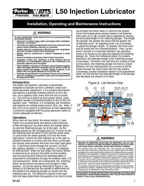
Introduction:The Watts L50 Injection Lubricator is specifically designed to lubricate air tools, cylinders, valves and other pneumatic equipment. It is a positive feed device that delivers a precisely metered amount of oil to the tool, via a capillary tube, every time the tool is turned on. The L50 has a built-in air flow sensor which, when activated, causes a pressurized piston to fire oil into the capillary tube. Therefore, it is completely self contained and requires no outside power source, time, etc. Note: If the L50 is to be used in a continuous air flow application, it should be equipped with the pulse generator option to ensure adequate oil delivery.Operation:Every time air flow starts, the sensor piston (1) (see Figure A) is pushed down and allows a pilot pressure to flow through port (2) which drives the module piston (3) and the metering plunger (4) to the right. As theplunger passes by the oil supply port (5), it forces oil into the metering tube (6) which in turn lifts the check valve (7) and forces the same quantity of oil into the inner sight glass, it drives the flow indicator (8) to the right (a positive indication of oil flow) and then flows up through the annular area between the inner and outer sight glass (9). It next flows down through the out port (10) and the capillary adapter (11) to the capillary (12) adapted for internal feed. When air flow stops, the sensor piston is returned by its spring to the initial no-flow position, and the pilot pressure behind the metering piston isexhausted to atmosphere through the exhaust valve (13) and exhaust port. When air is exhausted, the metering piston spring returns the piston and plunger to initial position. As can be seen by referring to Figure A, the amount of oil injected into the system is determined by the distance the metering plunger (4) travels into the metering tube (6). The distance it travels to the right(into the tube) determines the quantity of oil that is forced Figure A: L50 Section ViewL50 Injection LubricatorWARNINGTo avoid unpredictable system behavior that can cause personal injury and property damage:• Disconnect electrical supply (when necessary) before installation, servicing, or conversion.• Disconnect air supply and depressurize all air lines connected to this product before installation, servicing, or conversion.• Operate within the manufacturer’s specified pressure, temperature, and other conditions listed in these instructions.• Medium must be moisture-free if ambient temperature is below freezing.• Service according to procedures listed in these instructions.• Installation, service, and conversion of these products must be performed by knowledgeable personnel who understand how pneumatic products are to be applied.• After installation, servicing, or conversion, air and electrical supplies (when necessary) should be connected and the product tested for proper function and leakage. If audible leakage is present, or the product does not operate properly, do not put into use.• Warnings and specifications on the product should not be covered by paint, etc. If masking is not possible, contact your local representative for replacement labels.! WARNINGFAILURE OR IMPROPER SELECTION OR IMPROPER USE OF THE PRODUCTS AND/OR SYSTEMS DESCRIBED HEREIN OR RELATED ITEMS CAN CAUSE DEATH, PERSONAL INJURY AND PROPERTY DAMAGE.This document and other information from The Company, its subsidiaries and authorized distributors provide product and/or system options for further investigation by users having technical expertise. It is important that you analyze all aspects of your application, including consequences of any failure and review the information concerning the product or systems in the current product catalog. Due to the variety of operating conditions and applications for these products or systems, the user, through its own analysis and testing, is solely responsible for making the final selection of the products and systems and assuring that all performance, safety and warning requirements of the application are met.The products described herein, including without limitation, product features, specifications, designs, availability and pricing, are subject to change by The Company and its subsidiaries at any time without notice.EXTRA COPIES OF THESE INSTRUCTIONS ARE AVAILABLE FOR INCLUSION IN EQUIPMENT / MAINTENANCE MANUALS THAT UTILIZE THESE PRODUCTS. CONTACT YOUR LOCAL REPRESENTATIVE.!out through the check valve (7) and into the system. Since the module piston always travels a set distance from point (A) to (B), oil feed rate is adjusted by varying the protruded length of the metering plunger. The longer the plunger, the greater the travel and the greater the oil feed per cycle. An adjusting knob (14) is provided to adjust the plunger length. To operate, the knob must first be pulled into the unlocked position. Then, as the knob is turned in a clockwise direction, the adjusting screw (15) moves to the right and extends the metering plunger (4). Since the module/air piston (3) remains stationary, the extended length of the metering plunger is increased. Therefore, the next time the module is fired (pressurized), the metering plunger will travel a longer distance into the metering tube (6) so more oil will be forced through the check valve and into the system. Conversely, counter-clockwise rotation of the adjustment knob (14) will shorten the extended length of the plunger and decrease the amount of oil feed.Integral Reservoir (“R” option)The L50 is available with an integral 10 oz. reservoir.The unit must be oriented so that the reservoir remainsin the vertical position, with the vent and fill plugs onthe top. To fill the unit, remove the large fill plug with ascrewdriver and pour oil into the unit. The petcock stylevent, on top of the reservoir, must be in the open positionfor the unit to work. If using with a pressurized or gravityfeed external oil supply, the vent must remain closed.External Reservoir (non-pressurized)When installing a lubricator for use with an externalreservoir, the lubricator may be oriented in any position.The plumbing from the reservoir must be connected tothe oil port on the lubricator closest to the top (ceiling).The plumbing from the reservoir must not have any loopsor bends that would allow air to be trapped.External Oil Supply (pressurized)When installing a lubricator for use with an externalreservoir, the lubricator may be oriented in any position.The plumbing from the reservoir must be connected tothe port on the lubricator closest to the bottom (floor).A vent, or petcock, must be placed in the port closestto the top (ceiling) to allow purging of air from the oilsupply. It is recommended that a small reservoir capableof handling 3 or 4 cubic inches be connected to the portclosest to the top (ceiling) to trap any air bubbles fromthe oil supply. It is recommended that a shut-off valveand strainer be installed in the oil supply line as close tothe L50 as possible.It is recommended that the L50 be installed immediatelydownstream of a particulate/moisture removal air linefilter, and a pressure regulator, in order to insure longlife and trouble-free performance. In most cases, it isdesirable to use the 1/8" diameter nylon capillary tubingto deliver oil down the inside of the air supply pipe, orhose, to the point of use. In these cases, thread thecapillary tubing into the pipe prior to assembling to theoutlet port of the lubricator. If the capillary tubing isinserted into standard pipe, cut the capillary tubing sothat it is approximately 6" from the inlet port of the airdevice. If the tube is inserted into a flexible hose, cutthe capillary approximately 10% shorter than the hoseto allow for diameter expansion and resultant shorteningof air hose length. After the capillary tube is installed,connect the lubricator inlet port to the air supply line,connect the capillary tube to the lubricator barbed oiloutlet, and then connect downstream air piping.CAUTIONPolycarbonate bowls, being transparent and tough, are ideal for use with Filtersand Lubricators. They are suitable for use in normal industrial environments, butshould not be located in areas where they could be subjected to direct sunlight,an impact blow, nor temperatures outside of the rated range. As with mostplastics, some chemicals can cause damage. Polycarbonate bowls should notbe exposed to chlorinated hydrocarbons, ketones, esters and certain alcohols.They should not be used in air systems where compressors are lubricated withfire-resistant fluids such as phosphate ester and di-ester types.Metal bowls are recommended where ambient and/or media conditions arenot compatible with polycarbonate bowls. Metal bowls resist the action of mostsuch solvents, but should not be used where strong acids or bases are presentor in salt laden atmospheres. Consult the factory for specific recommendationswhere these conditions exist.TO CLEAN POLYCARBONATE BOWLS USE MILD SOAP AND WATERONLY! DO NOT use cleansing agents such as acetone, benzene, carbontetrachloride, gasoline, toluene, etc., which are damaging to this plastic.Bowl guards are recommended for added protection of polycarbonate bowls wherechemical attack may occur.!Oil Priming:The L50 and PL50 lubricators are shipped from the factory essentially free of oil. Therefore, it is imperative, particularly on installations with long capillary tubing lengths, that the lubricator be primed after installation prior to start-up. The reason for priming the lubricators is to evacuate all air from the oil passages and metering tubes in the lubricator. Each module in these lubricators is a small air operated hydraulic pump. Due to the small displacement of the piston/bore in these modules, itis imperative that all air be evacuated because each module must force the oil through an internal check valve. If air is present, the modules will not build up enough pressure to overcome the internal check valve due to the compressibility of air. There are two methods of priming – using a bucket pump, or manual priming: Manual Priming:To manually prime the lubricators, the oil supply should be connected and/or filled.With Integral Reservoir:The reservoir should be filled with oil and the ventcock should be left open.With External Reservoir or Oil Supply:The plug in the “Supply” port, on the plate atop theinjector, should be removed until oil starts to flowfrom the hole. The plug should then be replaced. The red, module adjustment knob should be pulled out and turned clockwise until it stops. At that point manually pump the adjustment stem (sticking out of the center of the adjusting knob) until oil can be seen flowing through either the sight dome or the capillary tube. It is not necessary for all air to be evacuated from the sight dome, as long as oil can be seen flowing through it while pumping.Bucket Pump Priming:The easiest method of priming an injection lubricator is with the use of a Button Head Fill Fitting and a bucket pump. Models with the “Q” option use an SA606Y107 Button Head Fill Fitting (which can also be purchased separately). The bucket pump is a small, manually operated, hydraulic pump with an oil reservoir. It is equipped with a hose and a fitting that will mate to the button head fill fitting, and is used to force oil into the oil passages, through the metering tubes, internal check valve, and out through the sight dome (if so equipped) and capillary tubes, purging all of the air from the injectors. T o prime with this method, simply connect the pump to the button head fill fitting and operate the bucket pump until oil is forced through the capillary line.Oil Module Adjustment:The adjustment knob has two positions. All the way inis locked, and one stop out is to adjust. For maximumoil feed adjustment, turn the adjustment knob clockwise until it stops, and then out two turns (16 clicks). To shut off oil feed rate, turn the adjustment knob a minimumof six counter-clockwise turns from the stop. (There is no stop on counter-clockwise rotation of the adjustment knob so do not turn it more than ten turns, except when disassembling the plunger for cleaning or replacement.) If the unit is equipped with a Cycle Counter, you may turn the selector to the “Off” position to turn the lubricator off. See page 4 for detailed setting instructions.There is an arrow on the adjustment knob to assist in determining fractional turn settings. Once oil feed is adjusted to desired level, push the knob in to lock it in place. Do not remove the knob for operation, as the adjusting screw will lose its adjustment.Note: The red indicator piston on the outlet side of the lubricator is designed to operate in the upper half of the oil adjustment range i.e., ¼ to ½ drop per cycle. If the module is adjusted for minimal oil delivery, the indicator may not show movement.Cycle Counter Adjustment:The cycle counter has four positions:Off: Oil injector module will not operate1: Oil Injector module operates with every cycle5: Oil injector module operates every fifth cycle10: Oil injector module operates every tenth cycle Pulse Generator Adjustment:The pulse generator is adjustable to operate the oil injector module every 1 to 20 seconds. This option is generally used where the flow per cycle exceeds 10 SCFM (see table to calculate).In order to adjust the oil injector module, cycle counter and/or pulse generator, the following steps must befollowed:1.) Determine the air flow consumption in SCFM(Standard Cubic Feet per Minute) of the tool orapplication to be lubricated. This information should be available from the tool or application's instruction sheet, or by contacting the manufacturer.2.) Measure the cycle “ON” time for which thetool/application is actually energized by using astopwatch to measure the time when the tool/application is running with air flowing through it. 3.) Calculate the flow in SCF (Standard Cubic Feet) percycle with the following formula:Application Flow Rating (SCFM) * 60 Flow per cycle =(SCF) 604.) Set injector module and cycle counter , or pulsegenerator (if equipped) using the chart below:Oil Delivery Chart1.) Injector actuates when tool/equipment is activated,but no oil is dispensed.2.) Injector module does not actuate when tool/equipment is activated.3.) Air leaks constantly from grooves in sensor bodyunder the injector module.4.) Air and/or oil leaks from top or bottom of injectormodule, cycle counter, or pulse generator.5.) Cycle counter does not make injector fire at thepre-determined 12, 24, 48, 96 or 192 cycle count.6.) Cycle counter allows injector to fire all the time (ormore than it should).7.) Pulse generator not timing consistently.Check to make sure oil supply is adequate and that injector has been properly primed and purged of all air in oil supply (see priming instructions).The minimum airflow through the lubricator must be at least 5 SCFM or injector module will not fire.This is generally caused by foreign material being caught in the flow sensor piston bore in the sensor body preventing it from closing.O-ring seals are either cut or misaligned or two Phillips head screws holding the top-plate are loose.The two Phillips head screws holding the top-plate are over-torqued (should be 30-40 in. lbs.) or internal counter problem.The two Phillips head screws holding the top plate are under-torqued (should be 30-40 in. lbs.) or internal counter problem.The air logic timer has become contaminated with either liquid or particulate matter.Problem Probable Cause Injection Lubricator TroubleshootingDependable Oil DeliveryL50 In-Line Injection Lubricators provide positive oil displacement lubrication ensuring the predetermined amount of oil is delivered to the tool each and every cycle regardless of pressure or flow.For best results unit must be used with capillary line inside air outlet or with coaxial tool hoses (see accessories).Features:• Air Flow SensorSingle point injection lubricators are installed between a filtered, regulated air source and an air supply hose going to a pneumatic tool. The body of the unit is designed to sense air flow when the tool is being used and signal the oil injector module to lubricate.• Oil Injector ModuleThe oil injector module provides adjustable oil delivery in amounts up to 1 drop per cycle. Oil delivery adjustment is made by turning the adjusting knob increasing or decreasing the oil piston travel in the module. Unit comes standard with oil delivery indicator.• Cycle Counter - 4 Position - OptionalWith the adjustable cycle counter, the lubricator can be set to dispense oil in the following manner: Setting: Off No oil dispensed1 Every cycle of the application 5 Every fifth cycle of the application10Every tenth cycle of the application• Pulse Generator - OptionalFor long cycle time applications the pulse generator makes the lubricator dispense a pre-determined amount of oil multiple times during a single tool cycle.Ordering InformationL50 — 04 R NO QOptionsQ Button Head Fill Fitting X64 Fluorocarbon Elastomersin Injector ModuleCounter / Generator Options Blank No Cycle Counter or Pulse Generator NO 4 Position Adjustable Counter G Adjustable Pulse GeneratorReservoirBlank No Reservoir R 10 oz. Integral ReservoirPort Size 04 1/2"06 3/4"Threads — NPT G BSPMaterials of ConstructionInjector ModuleBody ..................................................................................Aluminum Oil Piston ...................................................................................Steel Air Piston ................................................................................Ultem Sight Dome ..................................................................Polyurethane Springs ......................................................................................Steel End Plug ...................................................................................Brass Seals ...............................................Buna-N (Fluorocarbon Optional)Flow Sensor BodyBody ...........................................................................................Zinc Bottom Plate .............................................................................Steel Sensor Piston .......................................................Aluminum / Brass Spring ........................................................................................Steel Top Plate ....................................................................................Zinc ReservoirTop & Bottom Plate ...................................................................Zinc Reservoir Cylinder ....................................................Polycarbonate Seals ......................................................................................Buna-N Cycle CounterBody .........................................................................................Nylon Seals ......................................................................................Buna-N Pulse GeneratorBody ..................................................................................Aluminum Timer .............................................................Acetal / Steel / Buna-NRepair Kits and AccessoriesInjector ModuleSight Dome End Repair Kit ..............................................RKL50SD Module Kit .............................................................................KL50M Sensor BodySensor Piston ...............................................................SAL50-0472Button Head Fill Fitting .....................................................SA606Y107Integral 10 oz. Reservoir ........................................................BKL50R Cycle Counter Kit ................................................................RKL50NO Pulse Generator Kit ................................................................RKL50GSpecificationsOil Supply Pressure Range .................Gravity Feed to 30 PSIG Max.Oil Viscosity Range ....................................................150-1200 S.S.U.Minimum Airflow for Operation ..............................................5 SCFM Oil Delivery Range .................................0-1 Drop per Cycle of Injector Pressure Drop ....................................Less than 5 PSIG @ 100 SCFM Oil Fill Port .............................................................................1/8" NPT Maximum Pressure ..................................................................150 PSIAmount Of Oil Injected Per Machine (Tool) Cycle With Cycle CounterL50 DimensionsABC DEStandard Unit4.13(104,8) 3.48(88,4)1.38(35)5.09(129,3) 2.44(61,9)For Integral Reservoir Add: 3.0(76,2) 2.01(51)For Cycle Counter Add:0.88(22,4)For Pulse Generator Add:1.75(44,5)2.06(52,3)DimensionsParker Hannifin Corporation Pneumatic Division。
工程机械集中润滑系统

集中润滑系统在工程机械中的应用更低的维护成本更出色的产品性能销和衬套必须每天润滑为了提高销和衬套的使用寿命,我们建议提高润滑频繁,以确保衬套内有足够的润滑保护,以此减少磨损。
同时有效的防止灰尘、沙子和水进入。
这些污染物对销和衬套有致命性影响,能导致异常停机从而增加维护成本。
如果采用手动润滑,每台机器每天的润滑时间不少于30分钟。
每天都做到手动润滑并不容易,因为受限于:•天气条件•生产需求(集中润滑可在机器运行时进行工作)•安全(员工必须对机器的各个润滑点进行润滑)•物流(不一定随时有手动润滑设备可用)•润滑点过多•不是所有员工都能保证正确润滑不能保证润滑到每一个润滑点、每一台机器,或者不能保证每一次的润滑需求,都会对机器造成损伤,因此,维修的“及时”性非常重要。
当手动润滑一套轴承时,最常见的问题是:•润滑脂不能均匀的分布在衬套内•未实现完全润滑(注油量不足)手动润滑不正确,造成的成本•维修和更换备件成本•意外故障造成的停机•增加衬套、销等元件的磨损•降低设备使用年限•过度润滑造成的油脂浪费和环境污染只有自动润滑系统才能保证定期润滑建议:•定期润滑选用自动润滑系统•润滑需求超过250小时的润滑点,可采用手动润滑集中润滑的优点:•在机器运行时,自动完成润滑,每天可节省30-45分钟维护时间;•可实现定期和精准润滑,保证备件的使用寿命,减少维修成本;•通过设定的润滑量对润滑点实行润滑,减少油脂浪费;•润滑工作不受环境和天气影响;•增加设备的二次销售价格。
VIC产品优势:使用VIC自动润滑系统,在机器运转时,可“定时”、“定量”地为每一个润滑点进行润滑。
这种润滑方式能保证在销和衬套周围产生油脂密封圈,以此作为防止污染的屏障。
与手工润滑不同的是,每一次自动润滑所用油量相等。
自动润滑系统如何工作系统描述一套标准的自动润滑系统包括:电机、泵、分压器(含计量单元)、主油管、次级油管和可选部件(例如:报警装置、压力表、单向阀)组成。
设备润滑Pulsarlube KLT注脂器
设备润滑Pulsarlube KLT注脂器现如今,人们的生活水平提高了,科技发展也迅速了,越来越多的自动化产品代替了人工产品,不仅提高的生产率,降低了成本,还节省了大量的时间去做更重要的事情。
美国高科技产品-设备润滑Pulsarlube KLT注脂器(Vairable自动注油器、Pulsarlube V 帕尔萨单点润滑器)就是一款新型的著有设备,相对于人工注油来说,该产品大大降低了劳动力、生产成本、节约时间。
而且这种产品操作简单,只要稍稍一摁按钮,选个周期,就会自动的,无需人看管着给您的设备轴承注入新鲜的润滑剂。
设备润滑Pulsarlube KLT注脂器是在生产过程中延长轴承生命的一种装置。
他的工作原理主要是Variable是在受压状态下,通过产生惰性氮气的控制反应,递送自身包含的(预包含的)润滑油。
靠金属酸性反应,填充不同于传统气体的润滑器用可燃氢(氢气)。
使用了由微处理器控制的惰性氮气,这是广泛用于车辆的类似安全气囊的技术。
设备润滑Pulsarlube KLT注脂器是电化学、自动化的单点润滑器新一代品种,它的设计能确保在工业领域广泛应用上可精确、可预见、新鲜的供应润滑油。
该产品最大的优点就是带有触摸屏,可以清晰地看到注油量、注油时间,一目了然。
轻松自然。
该注油器事故高性能润滑器,它的产生代替了原始人工注油的时代,它拥有着精确的注油量,最大工作压力是4.8Mpa,因此它是单点使用的,只能注入油脂,一次性的,用完之后不会再用,成本低廉,使用方便。
产品相关说明:操作温度:- 4华氏度-140华氏度最大工作压力:4.8Mpa滑脂容量:125cc/ 250 cc防爆证明: Ex ia IIB T45种标准油脂( 多用途、耐用、高速、食品级、高温)设备润滑Pulsarlube KLT注脂器一般应用在危险或不宜进入的地方、受污染、润滑器保养人员不够的地方等。
设备润滑Pulsarlube KLT注脂器好处多多,轻松快捷解决您的注油问题,设备轴承的磨损、生锈将不复存在。
自动注脂器(机械式)
机械式自动加脂器
自动加脂器S100通过上下推送的方式来缓解油脂分离的问题,上行活塞可防止油脂在重力作用下漏出,同时将润滑油脂完全保留在润滑油箱内,防止润滑脂硬化,可以完全清空加脂器中的润滑脂。
技术参数:
产品型号:S100
油脂容量:100cc (90g)
工作温度:-23℃~121℃
安装规格:1/4"PT
机械式自动加脂器采用逆加压方式加压,可以改善离油度,并提高供脂可靠性;选择型阀门设计,便于调节油量,可以提前调整设置量;采用加压锁定装置,安装简易;采用12档调节盘,方便调节喷油量。
适用领域:
将产品用于以下部位的装置上,可大大提高效果:
•辊子、轧辊轴承
•防尘轴承
•开放型轴承
•需清洁轴承的部位
注意事项:
1、如果油脂量过多,可能会损坏产品,请注意避免活塞降至“Do not fill below this line”以下
2、建议使用手动加脂枪注油,切勿使用高压
3、如果使用含有空气的润滑剂,不但加快容器内部润滑脂硬化,注脂时因气压过高还可能损坏容器。
- 1、下载文档前请自行甄别文档内容的完整性,平台不提供额外的编辑、内容补充、找答案等附加服务。
- 2、"仅部分预览"的文档,不可在线预览部分如存在完整性等问题,可反馈申请退款(可完整预览的文档不适用该条件!)。
- 3、如文档侵犯您的权益,请联系客服反馈,我们会尽快为您处理(人工客服工作时间:9:00-18:30)。
VICSEN新一代全自动润滑脂加注器维克森(北京)科技有限公司VICSEN(BEIJING)TECHNOLOGY CO.,LTD.1产品介绍 标准电动油脂式———————————————2~8防爆电动油脂式——————————————9电动稀油式————————————————10零部件—————————————————11~13 实用案例————————————————14~182产品介绍 VICSEN-PUL 全自动润滑脂加注器【工作原理】 根据微处理器中存储的时间运行小型减速电机, 带动位于泵内部的涡轮,通过立式活塞的往复运动 吸入、喷出容器内润滑脂。
该装置含有一个垂直的给料泵、电机/齿轮组和 微处理器控制系统,允许高压工作。
可设定 6 个剂量 频率:1,2,3,6 和 12 个月以及半个月。
易读的液 晶显示器为设定操作和状态监测提供了所有必要的信 息。
润滑脂袋和电池组可根据专用润滑脂更换,该保 证润滑部位可按需得到润滑脂,保证润滑质量。
【特点】 特 点 优 点可任选注油周期 设定日期显示功能 注脂日数告知功能 止喷日期显示功能 电池诊断功能 差压诊断功能 测试功能 自动锁定能 供脂可靠性 降耗环保单触即可选择 15 日(半个月) 、1、2、3、6、12 个月 喷油周期中自己希望的周期 显示所选喷油周期及当前使用日数,便于肉眼观察 选择所需模式后过 30 秒时,切换至自动锁定功能,并 显示逆算的注油日数 显示停止喷油日期,便于供油管理 (搭载喷油日期保存 功能) 显示电池容量状态,准确告知更换时间 显示因供油量过多或管道阻力等差压过大而引起的供 油受阻情况 用于确认动作、急速喷油(清除) 、电机负载诊断等各 种目的 保护操作者设定的注油周期的功能 工作压力(20kgf/cm2)高,可适用于远距离安装 只要更换滑脂及电池盒,即能重复使用, 从根本上防止 环境污染3【产品规格】 项 尺 目 VICSEN-PUL125cc/250cc/500cc 125cc:ø91×183mm (h) 、250cc:ø91×210mm (h) 、500cc:ø101mm×240mm (h) 125cc/250cc/500cc DC4.5Volt(交换用) 标准规格:碱性电池 选项规格:锂电池 标准电池:-10℃~50℃ 选项电池:-40℃~60℃ 20kgf/㎠ 3/8”PT 1/2(15 日) 、1、2、4、6、12、18、24 个月(8 种模式) 0.34cc/20˚C(125cc), 0.34cc/20˚C(250cc) ,0.34cc/20˚C(500cc) 46~10000cst@40˚C 360 次 125cc,720 次/250cc,1440 次/500cc 寸 内 容产品型号 油囊容量 电 源工作温度 工作压力 安装规格 喷油周期 喷 油 量 油 粘 度 总行程数注意:随相对温度、热源(辐射热)情况等使用环境或油脂种类,使用温度及喷油量 可能存在差异。
【维 修 包】 区 分 油脂囊 防尘盖 标准碱性电池 锂电池 (低温、 高压 & 设定 24 个月 时使用) 电池盒 (共用)125cc 250cc500cc500cc500cc4【技术优势】 采用先进成熟的美国技术,原装进口美国产品; 机电驱动齿轮组推进活塞注脂; 完备的独立控制系统,可智能自动地向轴承供脂; 润滑周期可以自由设定、精确控制在 1/2~24 个月份时间内; 同步地监控空杯、低电量、以及轴承内部的反馈压力,维持在最低的平衡压力下自动 润滑,具有自检和报警功能; 可配 3~5 米管路,满足高温、强振动和危险环境下的润滑需要; 更换不同的润滑剂时无需调整参数,自动达到您的优化意图; 油脂用尽及油管堵塞报警,减轻巡检工作量; 干电池供电,无需外接电源,独立系统更加稳定,满足野外安装; 压力大,最大可加注 3#油脂; 整体封装良好,可用于各种润滑部位。
【系统组成】 由垂直给料泵、电机/齿轮组以及微处理器控制系统组成,它给出了一个得到的显著的 工作压力(280psa,20kg-f/cm2) 。
该润滑剂以 125cc/250cc/500cc 专业化油囊提供,这个袋 子可以随我们提供的电池组一同更换。
该注油器在一个单独装置中可提供从 1/2(半个月) 到 24 个月的 8 个可选择剂量比率。
【自动锁定系统】 微处理器在编程后的 60 秒内锁定液晶显示器。
非 I-Con 闪光锁在液晶显示器处于“锁 定-模式”时可见。
解除锁定液晶显示器,按住“mode”按钮 2 秒钟,直到锁定图标消失。
【电池低敏感容量】 低电池容量现象存在时,靠近测试模式按钮的红色发光二极管警告灯每秒钟闪亮一次。
【日常剂量比率显示】 在选择月设定后,日常剂量比率将会显示在液晶显示屏上。
液晶显示器将在该装置被 完成编程后的 60 秒自动锁定。
然后,液晶显示器显示天数,5(1)泵驱动周期表NO 1 2 3 4 5 6 7 8 9 10 模式设定 1/2个月 1个月 2个月 3个月 4个月 6个月 12月 18个月 24个月 测试 持续按2秒钟测试按钮 1行程/12小时 (2行程/日) 1行程/6小时(4行程/日) 1行程/24小时 (1行程/日) 1行程/12小时(2行程/日) 125cc行程/时间 250cc行程/时间 500cc行程/时间 1行程/1小时 (24行程/日) 1行程/0.5小时 (48行程/日) 1行程/0.25小时(96行程/日) 1行程/2小时 (12行程/日) 1行程/1小时(24行程/日) 1行程/4小时(6行程/日) 1行程/2小时(12行程/日) 1行程/6小时(4行程/日) 1行程/3小时(8行程/日) 1行程/2小时(12行程/日) 1行程/3小时(8行程/日) 1行程/6小时(4行程/日) 1行程/9小时(2.66行程/日) 1行程/12小时(2行程/日) 1行程/0.5小时(48行程/日) 1行程/1小时(24行程/日)(2)模式设定指南轴承直径 125CC 注脂量 (cc/Day) 230-330mm (9" - 13") 166-229mm (6 1/2” - 9”) 102 - 165mm (4” - 6 1/2”) 90 - 101mm (3 1/2” - 4”) 77 - 89mm (3” - 3 1/2") 65 - 76mm (2 1/2 - 3”) 51 - 64mm (2 ~ 2 1/2”) 25 - 50mm (1 ~ 2”) 12个月 0.3 24个月 0.3 6个月 0.7 12个月 0.7 3个月 1.4 6个月 1.4 12个月 18个月 24个月 1.4 0.9 0.7 2个月 2.1 4个月 2.8 6个月 2.8 1个月 4.2 2个月 4.2 4个月 4.2 1/2 个月 8.3 1个月 8.3 2个月 8.3 不推荐 15天 16.6 1个月 16.6 不推荐 不推荐 250CC 注脂量 (cc/Day) 15天 500CC 注脂量 (cc/Day) 33.36【多重供脂润滑系统】(1)分配阀 分配阀是靠连续工作的活塞将高压油定量自动供应至喷油口的装置,可同时对 2~8 个喷油口供脂。
一般为偶数。
设定的注油周期随着供油轴承数量的增加相应降低。
(2)多重供脂系统安装注意事项 - VICSEN-PUL250cc 全自动润滑脂加注机可在设备运转中更换,通常选择便于操 作及维修的位置安装。
- 联接分配阀管道式,如有剩余喷油口,切勿用塞子堵塞。
- 采用横桥(crossbridge)联接不必要的喷油口。
(横桥联接管喷油量会增加 2 倍) - 运行 1 个循环后分配阀的指示器(Indicator)会前进/后退,如任何一个管道被堵 塞时分配阀将停止工作,因此可通过肉眼容易发现异常情况。
- 尽量选择注油点附近安装,以减少管路损失。
- 如注油点位于活动部(上下/左右运动或严重振动) ,应使用软管。
- 如注油点超过 2 个,禁用分配器,建议使用分配阀。
- 包括连接管在内所有附件应注入同种规格润滑脂。
- 润滑脂应适合于润滑点,且便于利用润滑供油装置吸入/压送,滑脂硬度需要采用 软质 NLG1#1。
- 采用管道连接的供脂7参 考:上表条件为室温 20℃为准。
【多重供脂安装装图】 多点所需配件组装方法 1. 机械设备运行当中可以更换, 选择容易操作及维修的位置 2. 利用螺丝(4)固定支架(3) 3. 远距离安装时最多不超过 5m 4. 利用特氟龙带缠绕管件(2), (5),(6),(7)后旋转组装 先组装分配阀(8)后利用快插 接头(9)连接油管注意事项 1. 所有连接部必须缠绕特氟龙带 彻底密封 2. 所有零件包括连接管道必须注 满同样油脂8VICSEN-PUL500cc稀油全自动加注器:【产品介绍】VICSEN-PUL500cc稀油全自动加注器由靠微处理器控制的设计成立式自吸泵结构的本体和500cc容量油筒及电池组构成。
补充油同时更换电池盒时可永久使用。
【产品规格】油筒容量 500cc电源 DC 4.5Volt(交换用) 标准规格:碱蓄电池可选规格: 锂电池工作温度条件 标准电池:-10℃~50℃ 可选电池:-40℃~60℃使用压力 小于20kgf/cm2大小 高(240mm)×宽(101mm)重量 726g (空容器)喷嘴规格 PT 3/8 英寸油粘度 46 ~ 10,000 cst@40˚C喷油周期 1/2、1、2、4、6、12、18、24个月(8种模式) 多重供油 分配时小于4点警告:补充油时必需更换电池。
务必确认油成分是否与容器塑胶混溶或油是否符合使用条件。
关于其他技术性问题来电咨询本公司商务部。
【使用效益】降低设备维护成本降低轴承的更换费用降低轴承的库存成本降低工人劳动强度和维护的人力成本减少设备的故障时间减少意外停机损失保证生产的连续性避免意外事故的发生就实际工况适时润滑,不浪费任何一滴油系统可重复使用,配件更换简便,费用低廉配备油脂囊,设备可重复使用。
【应用场合】·空间狭窄,只能远距离安装的地方 ·需要注脂的所有工业用轴承类·发生巨大振动,不宜采用以往气体·空调设备(集尘器、鼓风机)·频繁发生高差压的地方·大型大厦内回转、空调设备·受灰尘及粉尘等污染后严重磨损轴承的地方 ·饮食业·需常注油,但不易注油的地方 ·水泥工业、矿山设备·汽车工业、电子工业设备·电机、泵类、回转设备·停机后才能注油的地方 ·传送带、各种机械设备式产品的地方 ·需减少维护费用的地方(如采·有色金属、炼铁、炼钢工业用分配阀,可对2、4、6、8个·造纸、纸浆工业注油点进行供油)现场状况:将维克森单点润滑脂自动加注机安装在易于操作的位置,通过铜管连接到加脂点,密封性能良好,实现了润滑的连续性,每3个月更换一次油脂。