诺瓦LED控制系统中文彩页
诺瓦科技LED显示屏控制软件SmartLCT用户手册
版权所有© 西安诺瓦电子科技有限公司2018。
保留一切权利。
非经本公司书面许可,任何单位和个人不得擅自摘抄、复制本文档内容的部分或全部,并不得以任何形式传播。
商标声明是诺瓦科技的注册商标。
声明欢迎您选用西安诺瓦电子科技有限公司(以下简称诺瓦科技)的产品,如果本文档为您了解和使用产品带来帮助和便利,我们深感欣慰。
我们在编写文档时力求精确可靠,随时可能对内容进行修改或变更,恕不另行通知。
如果您在使用中遇到任何问题,或者有好的建议,请按照文档提供的联系方式联系我们。
对您在使用中遇到的问题,我们会尽力给予支持,对您提出的建议,我们衷心感谢并会尽快评估采纳。
SmartLCT 显示屏配置软件用户手册更新记录更新记录SmartLCT 显示屏配置软件 (ii)更新记录 (ii)目录 (iii)用户手册目录目录1 简介 (1)系统架构...................................................................................................................................................... 2配置列表 (2)软件安装 (3)注意事项 (32)界面介绍 (4)3 语言设置 (6)4 离线操作 (7)界面介绍......................................................................................................................................................7新建项目 ......................................................................................................................................................9显示屏配置 ................................................................................................................................................104.3.1 添加箱体 (10)4.3.2 配置箱体走线 (11)12发送配置信息 ............................................................................................................................................13其他操作 ....................................................................................................................................................144.5.1 添加设备 (14)4.5.2 热备份 (14)5 在线操作 (17)界面介绍 (17)新建项目 (21)显示屏配置 (22)5.3.1 添加箱体 (22)5.3.2 配置箱体走线 (23)亮暗线调节 (23)5.4.1 界面介绍 (23)5.4.2 亮暗线参数调节 (25)SmartLCT 显示屏配置软件用户手册目录多批次调节................................................................................................................................................26监控 ...........................................................................................................................................................275.6.1 实时监控 (28)5.6.2 误码率检测 (29)5.6.3 版本信息 (29)5.6.4 监控配置.................................................................................................................................................29发送配置信息 ............................................................................................................................................30V-Sender (30)5.8.1 如何进入V-Sender? (30)5.8.2 工具栏功能介绍 (31)5.8.3 添加设备 (31)325.8.6 模板设置 (33)5.8.7 设备属性 (33)5.8.8 画中画 (34)5.8.9 拼接带载功能 (36)其他操作 (36)5.9.1 热备份 (36)5.9.2 Mapping .................................................................................................................................................. 366 特色功能 . (37)积木式搭屏 (37)90°倍数旋转 (37)360°任意旋转 (37)显示屏测试 (39)接收卡配置参数更新与回读 (40)主控设备和接收卡信息回读 (40)接收卡程序升级 (40)主控设备程序升级 ..................................................................................................................................... 40导出图 . (40)SmartLCT显示屏配置软件用户手册1简介1简介概述SmartLCT是诺瓦新一代显示屏配置软件,配合LED控制器实现对各种复杂LED显示屏的智能配置,其中包括:积木式配屏、离线(在线)设计、亮暗线调节、箱体旋转等,使显示屏的配置更加简单,致力于提升客户体验。
诺瓦科技LED显示屏同步控制系统MCTRL660PRO规格书

www.novastar.tech
i
MCTRL660 PRO Independent Controller Specifications
Change History
Change History
Version
Release Date
Description
V1.0.0
height.
CO The MCTRL660 PRO has various video connectors:
Input connectors: 1 × 3G-SDI, 1 × HDMI 1.4a, 1 × single-link DVI.
H Output connectors: 6 ×Gigabit Ethernet port, 2 ×10G optical port. C Loop output connectors: 1 × 3G-SDI LOOP, 1 × HDMI LOOP, 1 × DVI LOOP. TE The MCTRL660 PRO has many industry-leading advanced technologies: R Input of ultra-high color depths, such as 10-bit/12-bit 4:4:4, with input resolutions
H YCbCr 4:2:0 AR TEC 8-bit NOVAST 10-bit/12-bit
Maximum input resolution supported by standard program: 1920×960@60Hz.
Maximum input resolution supported by customized sending card and receiving card programs: 1920×1080@60Hz.
诺瓦科技Micro LED控台C1详细规格书中文版

声明
欢迎您选用西安诺瓦电子科技有限公司(以下简称诺瓦科技)的产品,如果本文档为您了解和使用产品带来 帮助和便利,我们深感欣慰。我们在编写文档时力求精确可靠,随时可能对内容进行修改或变更,恕不另行 通知。如果您在使用中遇到任何问题,或者有好的建议,请按照文档提供的联系方式联系我们。对您在使用 中遇到的问题,我们会尽力给予支持,对您提出的建议,我们衷心感谢并会尽快评估采纳 。
1
C1 规格书
C1
4 尺寸 5 使4 用尺场寸景
5 4 尺寸 使用场景
单位:mm
2
网址:
http://www.novast介 性
简介 外观
12 简特介 性
双液晶屏的触控设计,用户可以在操作的同时通过控台 C1 上的一个液晶屏观察到 输入源信息状态、Preview 监视状态以及 LED 显示屏上输出结果状态,做到控制
C1 是时诺心瓦中针有对数终、端掌视控频全处局理。产品专门研制的一款控台产品。主要应用于现场舞台控 制 。最大支持 16 台设备控制。 C 1 配支备持2对个诺液瓦晶终显端示视器频,拼一接个处显理示器屏进用行于控实制现。输入多画面预监,另一个显示屏与面板 上 的按支键持搭屏配体使拼用接,可快对速场拼景接中,的输图出层画大质小调,整位,置背,景输设入置源,,ED输ID出设分置辨,率测,试图画层面边,框正 和输入常源显截示取和进黑行屏配一置键。切换。 C 1 配支备持摇3杆2 和个场T-景Ba,r,并摇支杆持能自精定细义化场调景整的图添层加的和大删小除和。位置,T-Bar 支持 1024 等级划 分 ,能支精持细场控景制复场制景,的场切景换模效板果的。调用,自定义场景并保存自定义场景,场景数据清除
和场景区域锁定。 炫酷的灯光按键,高灵敏的摇杆和 T-Bar 加上双显示屏使得 C1 操作更加简单,极大地 方 便了最现大场支舞持台8 制个作图。层,1 路 OSD,1 路 BKG 和 1 路 LOGO 的设置。 支持异形图层和图层遮罩的配置。 支持一键添加图层,一键清除图层,图层一键置顶或置底。 支持图层编辑,图层画质调整,图层边框设定和图层冻结。 支持通过摇杆和按键控制图层大小及图层位置。 支持辅助输出配置,如提词器等。 支持单双链路输出设置。 支持输入源画面截取和图层克隆。 支持 13 种图层特效切换设置。 支持摇杆灵敏度的调节。 支持通过 T-bar 手动调整场景淡入淡出的特效切换。 支持通过 RJ45 接口远程或现场控制终端视频处理器。
诺瓦科技多画面全彩LED视频控制器K4S参数文档说明书
产品规格书
视频控制器K4S
Rev1.0.2 NS160110150
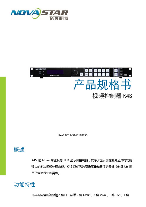
概述
K4S 是 Nova 专业级的 LED 显示屏控制器,其除了显示屏控制外还具有功能
强大的前端视频处理功能。
K4S 以优秀的图像质量和灵活的图像控制极大地满
足了媒体行业的需求。
功能特性
HDMI,1路DP,1路SDI;支持的输入分辨率最高可达1920×1200@60Hz;
K4S 可根据显示屏分辨率对输入图像进行逐点缩放;
2)提供无缝快切和淡入淡出等多种切换效果,以增强并呈现专业品质的演示
画面;
3)画中画的位置、大小等均可调节,可以随心所欲的控制;
4)采用 Nova G4 引擎,画面稳定无闪烁、无扫描线、图像细腻、层次感好;
5)根据屏幕所用 LED 的不同特性,实施白平衡校准及色域匹配,确保真实色
彩还原;
6)HDMI 音频输入;外置独立音频输入;
7)支持高位阶视频输入,10bit/8bit;
8)视频输出带载能力:230 万像素;
9)支持多台拼接带载;
10)支持 Nova 新一代逐点校正技术,校正过程快速高效;
11)无须通过计算机软件进行系统配置。
只需对一个旋钮和一个按钮进行操作即可
完成系统配置,所有操作几步即可完成,这就是我们所倡导的“司机点屏”!
12)采用创新型架构,实现智能配置,屏幕调试可在数分钟内完成,极大缩短
舞台准备时间;
13)一个直观的操作屏幕显示界面,清晰的按键灯提示,简化了系统的控制。
外观说明
前面板
后面板
规格参数
附件
PIP(画中画)信号源冲突列表。
诺瓦科技LED显示屏同步控制系统MCTRL500规格书
www.novastar.tech
第 4页
西安诺瓦电子科独技立有主规控限格MC公TR书L司500
V2.1.0 NS110000118
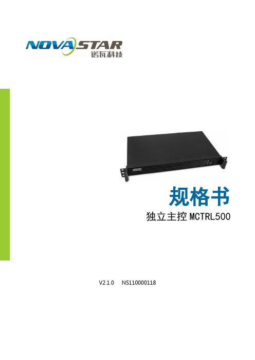
概述
MCTRL500 是诺瓦的大带载控制器,四路网口或光纤输出,单台最大带载 2048 ×1152 或 1920×1200。可级联多台统一控制。
功能特性
1) 一路 DVI 视频输入; 2) DVI 视频输出,用于级联或监视;
规格参数
输入指标
端口
数目
分辨率规格
DVI IN
1
VESA 标准
输出接口
端口
数目
分辨率一致
限公司 整机规范 技有 整机功耗 科 工作环境温度 子 工作环境湿度 瓦电 净重 西安诺USB 线
16 W -20~60℃ 0~95% 2.9 Kg 1.5 M
DVI 线
1.5 M
OUT1~4
4 路网口输出
OPT1~4
4 路光纤输出
控制接口
RS232 IN、OUT
级联输入、输出
电源
AC-100-240V-50/60HZ
交流电源接口
www.novastar.tech
第 2页
尺寸
19 寸 1U 标准机架结构。
西安诺瓦电子科技有限公单位司:mm
www.novastar.tech
第 3页
司 3) 一路音频输入; 公 4) 四个网口输出或四路光纤输出; 有限 5) RS232 接口控制,可级联多台进行统一控制; 西安诺瓦电子科技 6) 最大带载分辨率 2048×1152 或 1920×1200。
www.novastar.tech
第 1页
外观说明
指示灯
诺瓦科技LED控制卡MCTRL R5规格书

MCTRL R5 Independent ControllerSp e cificationsCopyright © 2018 Xi’an NovaStar Tech Co., Ltd. All Rights Reserved.No part of this document may be copied, reproduced, extracted or transmitted in any form or by any means without the prior written consent of Xi’an NovaStar Tech Co., Ltd.TrademarkChange HistoryContentsChange Historyis a trademark of Xi’an NovaStar Tech Co., Ltd.StatementYou are welcome to use the product of Xi’an NovaStar Tech Co., Ltd.( h ereinafter referred to as NovaStar). This document is intended to help you understand and use the product. For accuracy and reliability,NovaStar may make improvements and/or changes to this document at any time and without notice. Any problem in use or a ny good suggestion, please contact us through ways provided in the document. We will do our utmost to solve the problems and adopt the suggestions after evaluation as soon as possible.Independent Controller MCTRL R5SpecificationsContentsChange History (ii)1 1Safety ...............................................................................................................................................1.1Storage and Transport Safety (1)1.2Installation and Use Safety (1)3 2Overview ......................................................................................................................................... 3Features . (4)4Appearance (5)Dimensions (7)5Specifications (68)XI'ANNOVASTAR1 Safety1SafetyThis chapter illustrates safety of the MCTRL R5 independent controller to ensure the product’s storage, transport, installation and use safety.Safety instructions are applicable to all personnel who contact or use the product. First of all, pay attention to following points.● Read through the instructions. ● Retain all instructions. ●Comply with all instructions.1.1 Storage and Transport Safety● Pay attention to dust and water prevention.● Avoid long-term direct sunlight.● Do not place the product at a position near fire and heat.● Do not place the product in an area containing explosive materials. ● Do not place the product in a strong electromagnetic environment.●Place the product at a stable position to prevent damage or personal injury caused by dropping.●Save the packing box and materials which will come in handy if you ever have to store and ship the product. For maximum protection during storage and shipping, repack the product as it was originally packed at the factory.1.2 Installation and Use Safety● Only trained professionals may install the product.●Plugging and unplugging operations are prohibited when the power is on.●Ensure safe grounding of the product.●Beware of electric shock hazards.●Always wear a wrist band and insulating gloves.●Do not place the product in an area having frequent or strong shake.●Perform dust removing regularly.1 Safety●Contact NovaStar for maintenance at any time, rather than have the productdisassembled and maintained by non-professionals without authorization.●Replace faulty parts only with the spare parts supplied by NovaStar.LTD.CO.,TECHNOVASTARXI'AN2 OverviewIndependent Controller MCTRL R5 Specifications2OverviewDeveloped by NovaStar, the MCTRL R5 is the first independent controller thatsupports rotation function. With up to 3840×1080@60Hz loading capacity of a single unit, it can support any custom resolution within this range as required, thus meetingthe on-site configuration requirements of extra-long or extra-large LED displays. Working with the A8s or A10s, the MCTRL R5 supports free screen configuration onSmartLCT, presenting full rotation of the display screen at any angle, adding diversity to images, and bringing different visual experience to users.The MCTRL R5 is mainly applied to concert control centers, live events, security monitoring, Olympic Games and various sports centers.XI'ANNOVASTARTECHCO.,LTD.3 Features4 Appearance3Features● Provides complete input connectors, including 1 ×6G-SDI, 1 × dual-link DVI and 1 × HDMI 1.4. ●Supports 8 × Gigabit Ethernet ports and 2 × fiber optical outputs.● Supports rotation of LED screens at any angle. ● Adopts innovative architectural design to enable smart configuration, which cangreatly shorten the stage preparation time. ● Adopts NovaStar G4 engine to realize a perfect image display with no flickering and scanning lines, but fine quality and good sense of depth.● Supports NovaStar's latest pixel level calibration technology with a fast andefficient process.● Implements white balance calibration and color gamut mapping to ensure colors are faithfully reproduced.●Supports screen configuration at any time without a PC.● Supports easy and quick manual adjustment of screen brightness. ● Supports hardware upgrade via USB on the front panel.●Supports cascading multiple controllers for uniform control.XI'ANNOVASTARTECHCO.,4 Appearance Rear PanelIndependent Controller MCTRL R5 SpecificationsNote:USB portprohibitedbeingto thecomputerIndependent Controller MCTRL R5 Specifications5DimensionsUnit: mmXI'ANNOVASTARTECHCO.,s6SpecificationsLTD.XI'AN。
诺瓦科技LED视频控制器VX6s规格书
VX6s二合一视频控制器规格书文档版本:V1.0.0文档编号:NS160000263版权所有©2018 西安诺瓦电子科技有限公司。
保留一切权利。
非经本公司书面许可,任何单位和个人不得擅自摘抄、复制本文档内容的部分或全部,并不得以任何形式传播。
商标声明是诺瓦科技的注册商标。
声明欢迎您选用西安诺瓦电子科技有限公司(以下简称诺瓦科技)的产品,如果本文档为您了解和使用产品带来帮助和便利,我们深感欣慰。
我们在编写文档时力求精确可靠,随时可能对内容进行修改或变更,恕不另行通知。
如果您在使用中遇到任何问题,或者有好的建议,请按照文档提供的联系方式联系我们。
对您在使用中遇到的问题,我们会尽力给予支持,对您提出的建议,我们衷心感谢并会尽快评估采纳。
网址:规格书 1 概述1 概述VX6s是集视频处理和发送卡于一体的二合一视频控制器,具备强大的视频信号处理能力,支持7路视频信号输入,同时支持6个千兆网口输出。
基于强大的FPGA处理平台,VX6s支持快速无缝切换和淡入淡出等多种切换特效,可以提供灵活的屏幕控制和优异的图像显示。
规格书 2 特性2 特性●支持多达7个输入接口,包括2路3G-SDI,2路HDMI1.3,2路DVI,1路USB播放。
●支持3个窗口和1路OSD。
●支持快捷配屏和高级配屏功能。
●切换台模式下支持T ake键一键上屏。
●支持输入分辨率自定义调节。
●支持设备冗余设置。
●视频输出最大带载:390万像素。
●支持带载屏体亮度调节。
●支持多台设备拼接带载。
●支持窗口全屏自动缩放。
●视频输出最大宽度为4096像素。
●支持创建16个用户场景作为模板保存,可直接调用,方便使用。
●支持选择HDMI输入源或DVI输入源作为同步信号,达到输出的场级同步。
●前面板直观的OLED显示界面,清晰的按键灯提示,简化了系统的控制操作。
3 外观前面板后面板规格书 4 尺寸4 尺寸单位:mm规格书 5 应用场景5 应用场景。
诺瓦科技LED屏同步控制系统MCTRL4K规格书

HDMI 2.0 接口,支持 HDCP 1.4 和 HDCP 2.2
公司 双链路 DVI 接口
1~16 OPT1~4 控制接口
16 路 Neutrik 千兆网口输出
有限 4 路光纤输出
ETHERNET
技 控制接口
USB GenLock
IN: 级联输入或与 PC 连接
子科 OUT:级联下一台
电 Genlock 类型:Blackburst
子科技有限公司
西安诺瓦电
产品规格书
独立主控 MCTRL4K
Rev1.0.1 NS1600000125
概述
MCTRL4K 是诺瓦科技开发的一款具有划时代意义的独立主控。单台带载高达 4096x2160@60Hz,可以满足现场对超长、超大屏的需求;也可以作为两台 独立主控使用,带屏更加灵活自由,为用户带来绝对震撼的使用体验。
科 4) 采用创新型架构,实现智能配置,极大缩短舞台准备时间;
子 5) 采用 Nova G4 引擎,画面稳定无闪烁、无扫描线、图像细腻、层次感好;
电 6) 支持 Nova 新一代逐点校正技术,校正过程快速高效;
瓦 7) 根据显示屏所用 LED 的不同特性,实现白平衡校准及色域匹配,确保色彩
诺 真实还原;
技 无连接或连接无效,左上角带角标表示连接有效且处于冗余状态; 科 ④:旋钮,按下旋钮表示进入或输入确定,旋转旋钮表示选择或参数调节; 电子 ⑤:BACK,退回上层菜单。
瓦
诺
安
西
www.novastar.tech
第4页
后面板
输入源
DP 1.2
DP 1.2 接口,支持 HDCP 1.3
HDMI 2.0 DUAL DVI-D1/D2 输出接口
LED同步控制系统MCTRL1600用户手册
4.1 亮度调节
返回主菜单界面, 按下旋钮, 选中亮度调节菜单的对应数值, 此时可转动旋钮调节亮度值。
4.2 输入设置
输入模式设置
MCTRL1600 支持 Dual Link 模式和 Single Link 模式。 输入源为 DVI 时,可以进行画面拼接(最多可实现四个画面的拼接)。
• •
Dual Link 模式时,视频源的输入方式包括 Auto、DP、D DVI×2。 Single Link 模式时,视频源的输入方式包括 Auto、DP、S DVI×4。
第3步 第4步 第5步 注意:
设置显示屏带载箱体的行数和列数。 设置网口 1 带载的箱体数。设备对网口带载数有一定的限制,请参见注意事项 a)。 设置屏体走线方式,请参见注意事项 c)、d)、e)。
a)如有带载的网口数为 n, 则前 n-1 个网口带载的 箱体数必须相等,且必须 是箱体行数或列数的整数 倍,同时需要大于或等于 第 n 个网口的带载数。
4 菜单操作
控制器开机后,显示屏显示主界面如下:
A:输入信号源的工作状态。 蓝色表示有信号,灰色表示无信号。DP 接口插拔时间间隔应大于 5 秒,否则会出现 DP 源不识别。 B:当前输入源的分辨率和帧频。 选择双链路 DVI 输入时,则交替显示两路 DVI 的源信息。 C:当前带载屏体的宽、高和帧频。 D:状态显示,各状态图标的含义如下。 主板核心供电电压 机箱内温度 屏体亮度 / / / / DVI1 和 DVI2 视频源同步 / 未同步 控制接口状态为未连接 / 连接 USB/ 连接 ETHERNET 屏幕未锁定 / 锁定 -4-
1.1 目录
1 概述��������������������������������������������������������������������������������������������������������������� 4 2 硬件结构�������������������������������������������������������������������������������������������������������� 5
诺瓦科技无线LED控制卡LED多媒体播放器TB1详细参数说明书

诺瓦科技LED视频控制器VX6s用户手册
3.3.2 输入画质调整 ........................................................................................................................................... 8
电磁干扰:设备应远离磁铁、马达及变压器。
防潮:请将设备置于干燥、干净的环境中。如有液体浸入,请立即拔掉 电源插头。
远离易燃易爆危险物品。
禁止液体、金属碎片浸入机器内部,以免引起安全事故。
www.noHale Waihona Puke
ii
二合一视频控制器 VX6s 用户手册
更新记录
发布版本 V1.0.0
发布时间 2018.07.24
修订说明 首次发布
前言
西安诺瓦电子科技有限公司
iii
二合一视频控制器 VX6s 用户手册
目录
目录
前 言................................................................................................................................................. ii
1 概述..................................................................................................................................................1
诺瓦科技LEDLED显示屏同步控制系统MCTRL R5用户手册英文版
MCTRL R5Independent ControllerProduct Version:V1.0.1Document Number: NS110100550User ManualXI 'AN N OVA S T AR T EC HCO .,L T D.Copyright © 2018 Xi’an NovaStar Tech Co., Ltd. All Rights Reserved.No part of this document may be copied, reproduced, extracted or transmitted in any form or by any means without the prior written consent of Xi’an NovaStar Tech Co., Ltd.Trademarkis a trademark of Xi’an No vaStar Tech Co., Ltd.StatementYou are welcome to use the product of Xi’an NovaStar Tech Co., Ltd. (hereinafter referred to as NovaStar). This document is intended to help you understand and use the product. For accuracy and reliability, NovaStar may make improvements and/or changes to this document at any time and without notice. Any problem in use or any good suggestion, please contact us through ways provided in the document. We will do our utmost to solve the problems and adopt the suggestions after evaluation as soon as possible.X I'A NN OV AS TA RT EC HC O.,LT D.User Manual Change HistoryChange HistoryX I'A NN OV AS TA RT EC HC O.,ContentsChange History ................................................................................................................................ ii 1 Safety ............................................................................................................................................... 1 2 Overview ......................................................................................................................................... 2 3 Hardware Structure.. (3)3.1 Appearance .................................................................................................................................................. 3 3.2 Dimensions .. (5)4 Homepage ....................................................................................................................................... 6 5 Menu Operations .. (8)5.1 Brightness Adjustment ................................................................................................................................. 8 5.2 Screen Settings ........................................................................................................................................... 8 5.2.1 Quick Configuration .................................................................................................................................. 8 5.2.2 Advanced Configuration ........................................................................................................................... 9 5.2.3 Image Offset ............................................................................................................................................. 9 5.3 Rotation Settings ....................................................................................................................................... 10 5.4 Input Settings ............................................................................................................................................. 10 5.4.1 Input Video Source Settings ................................................................................................................... 10 5.4.2 Input Resolution Settings ........................................................................................................................ 10 5.5 Display Control ........................................................................................................................................... 11 5.6 Advanced Settings ...................................................................................................................................... 11 5.6.1 Mapping Function .................................................................................................................................... 11 5.6.2 Loading Cabinet Files .............................................................................................................................. 11 5.6.3 Alarm Threshold ...................................................................................................................................... 12 5.6.4 Saving to Hardware ................................................................................................................................ 12 5.6.5 Redundancy ............................................................................................................................................ 13 5.6.6 Preset Template ...................................................................................................................................... 13 5.6.7 Hot Backup for Input Source .................................................................................................................. 13 5.6.8 Factory Reset ......................................................................................................................................... 13 5.6.9 Go Homepage (s) ................................................................................................................................... 13 5.6.10 Greyscale Adjustment ........................................................................................................................... 13 5.6.11 Hardware Version ................................................................................................................................. 13 5.7 Communication Settings ............................................................................................................................ 13 5.8 Language (14)XI 'AN NOVA S T AR T EC HCO .,L T D.6 Specifications (15)X I'A NN OV AS TA RT EC HC O.,LT D.User Manual 1 Safety1 SafetyTo avoid potential hazards, please use this product according to regulations. Poweroutlet should be installed near the unit and easy to reach. In the event of breakdowns,only trained personnel may disassemble it for maintenance, and please contact theafter-sales department of NovaStar for help.High-voltage hazard: Operating voltage of this product ranges from 100V to 240 V AC.Grounding: Ground connection of this product is enabled through powercords. Please make sure that ground conductors are in good condition.Electromagnetic interference: Keep this product far away from magnets,motors and transformers.Moisture proof: Keep this product in a dry and clean environment. Incase of liquid immersion, please pull the power plug out immediately.Keep the product away from flammable and explosive hazardoussubstances.Prevent liquids or metal fragments from dropping into the product inorder to avoid accidents.X I'A NN OV.,LT D.User Manual 2 Overview2 OverviewDeveloped by NovaStar, the MCTRL R5 is the first independent controller thatsupports rotation function. With up to 3840×1080@60Hz loading capacity of a singleunit, it can support any custom resolution within this range as required, thus meetingthe on-site configuration requirements of extra-long or extra-large LED displays.The MCTRL R5 supports HDMI, Dual Link DVI, SDI signal inputs, as well as 8Neutrik Gigabit Ethernet ports, and 2 optical fiber outputs.The distinctive and innovative design of the MCTRL R5 enables screen configurationwithout PC, diverse image rotation effects, and amazing visual experience for users.Note: The device must be powered off before connection.To control multiple MCTRL R5 units (10 units at most), please cascade them according to the figure below.X I'A NN OV AS TA RT EC HC O.,LT D.3Hardware Structure3.1 AppearanceFront PanelInstruction on knob operations:On the home screen, pressing the knob enters the main menu.XI 'AC HCO .,L T D.● On the main menu, rotating the knob selects a menu item or adjusts theparameter, and pressing the knob confirms the selection or enters the submenu. ●Holding down the knob and BACK button simultaneously for 5 seconds locks or unlocks all the buttons.Rear PanelNote : Type-A USB port is prohibited from being connected to the upper computer directly.XI 'A3.2 DimensionsUnit: mmX I'A NN OV AS TA RT EC HC O.,LT D.4HomepageAfter the MCTRL R5 is powered on, the home screen is shown in the figure below.Power voltage of the motherboard Temperature inside the deviceScreen brightnessXI 'AA S T AR T E C HCO .,L T D.1~2 Optical fiber ports connection: ●●//Control ports:Connects to USB/ Ethernet/ GenLock synchronization/Rotation enabled/lockedX I'A NN OV AS TA RT EC HC O.,5 Menu OperationsMCTRL R5 features powerful functions and simple operations. To achieve betterdisplay effects, users can choose to set other options in the menu.5.1 Brightness AdjustmentOn the main menu, press the knob to select the Brightness item and rotate the knobto adjust the brightness value.5.2 Screen Settings5.2.1 Quick ConfigurationBefore you start, load the cabinet configuration files and save them to the receivingcard.Step 1 Press the knob to enter the main menu.Step 2 Choose Screen Settings > Quick Config to enter the submenu, and rotate the knob to set corresponding options.●Set the row and column quantity of cabinets based on the actual condition of ascreen.●Set the cabinet quantity connecting to port 1. There are limits on the loadingcapacity of ports. Refer to a) in Note for details.●Set data flow of the screen, and refer to c), d), and e) in Note for details.X I'A NN OV AS TA RT EC HC O.,LT D.5.2.2 Advanced ConfigurationStep 1 Choose Advanced Config and press the knob to enter its submenu.Step 2 On the warning screen, click Yes to enter the advanced configuration screen. Step 3 Select Enable and set the parameters of targeted Ethernet ports.5.2.3 Image OffsetSet the horizontal offset and vertical offset of devices ’ loading image.XI 'AN N OVA S5.3 Rotation SettingsThere are 2 rotation methods: Port rotation and screen rotation.●Port rotation: Rotation of cabinets loaded by an Ethernet port (For example, set the rotation angle of port 1, and the cabinets loaded by port 1 will rotate according to the angle).●Screen rotation: Rotation of the whole LED screen according to the rotation angle set before.Rotation settings:Step 1 Choose Rotation Settings > Rotation Enable , and choose ENABLE . Step 2 Choose Port Rotate or Screen Rotate and set parameters. Step 3 Select Save to save your settings.Notes:● Hardware screen configuration is required to be done before the rotation settings. ●After screen configuration are done on SmartLCT, set rotation function on MCTRL R5, and a message “Reconfig screen . Are you sure?” will appear. Choose Yes to perform rotation settings.5.4 Input Settings5.4.1 Input Video Source Settings There are several types of input sources available for users to choose.5.4.2 Input Resolution Settings There are 2 methods to set input resolution:Method 1: Preset resolution Choose a proper resolution from the preset standard resolutions, or use method 2 tocustomize the resolution.Method 2: Custom resolutionRotate the knob to set the custom width (growing in even numbers), custom height, and custom refresh rate, and choose Apply . Press the knob to confirm the setting. If Apply is not enabled, the custom resolution is invalid.XI 'A N N O V A S T AR T EC HCO .,L T D.5.5 Display ControlNormal: Playing the input source normally. Black Out: The screen is black out, with no display. Freeze: Freezing the displaying image.Test Pattern: 8 test patterns including pure color and lines testing.Image Settings: Setting red, green and blue brightness, color temperature, Gamma rate, and saving parameters.5.6 Advanced SettingsAdvanced settings include settings of multiple main functions, as shown below.5.6.1 Mapping FunctionWhen Mapping Function is enabled, each of the cabinets will display the cabinet number and Ethernet port number it belongs to.5.6.2 Loading Cabinet FilesConnect to PC and start NovaLCT on PC, and import the saved cabinet configuration files.Step 1 Save cabinet configuration files.After configuring the receiving cards, click Save to File to save the cabinet configuration files (.rcfgx) to local PC.XI 'AN N OVA S T AR T EC HCO .,L T D.Step 2 Import the cabinet configuration files to the MCTRL R5.Note: After entering the Configuration File of Controller Cabinet Import window, NovaLCTwill automatically read the configuration files already existed in the MCTRL R5. Users can change the names and orders of these files or delete them.Step 3 Load the cabinet configuration files.5.6.3 Alarm ThresholdSet the ranges of temperature and voltage values.5.6.4 Saving to HardwareSave all the configurations related to the receiving cards to the receiving cards and those data will not be lost even after the device is powered off.XI 'AN N OVA S T AR T EC HCO .,L T D.5.6.5 RedundancySet the current device as the primary or backup device.5.6.6 Preset TemplateSave configuration information, rotation parameters, and user settings information astemplates. Users can add 10 templates at most.5.6.7 Hot Backup for Input SourceSet backup source for the current input source. The backup source should be othertypes of input source supported by the device.5.6.8 Factory ResetReset the current device to factory settings.5.6.9 Go Homepage (s)The current page stays for how many seconds before going homepage when there isno actions.5.6.10 Greyscale AdjustmentAdjust greyscale among the range from 4 to 15 for the LED display screen.5.6.11 Hardware VersionView the hardware version of current device. In case of new version release, accessNovaLCT through PC to upgrade the hardware version.5.7 Communication SettingsSet the communication mode and network parameters.Two communication modes are provided: USB Preferred and LAN Preferred. When the USB and Ethernet ports are connected at the same time, the system will use the communication mode set by the user.X I'A NN OV AS TA RT EC HC O.,LT D.Network settings include manual mode and auto mode. When setting the networkmanually, the IP address of current device cannot conflict with IP addresses of otherdevices.5.8 LanguageChange the UI language of the MCTRL R5 unit.X I'A NN OV AS TA RT EC HC O.,LT D.User Manual 6 Specifications6 SpecificationsX I'A NN OV AS TAD.。
诺瓦科技LED同步控制系统MCTRL1600用户手册

iii
独立主控 MCTRL1600 用户手册
目录
7.5.4 固化至接收卡 .......................................................................................................................................... 22 7.5.5 冗余设置 ................................................................................................................................................. 22 7.5.6 工厂复位 ................................................................................................................................................. 22 7.5.7 3D 设置 .................................................................................................................................................... 22 7.5.8 硬件版本 ................................................................................................................................................. 25 7.6 通讯设置.................................................................................................................................................... 25 7.7 工作模式.................................................................................................................................................... 25
诺瓦科技LED显示屏同步控制系统MCTRL4K用户手册

第二步 输入分辨率设置
用户可以按照自己的需求设置输入源的分辨率。
输入分辨率可以通过以下两种方式设置: 方式一:预设分辨率设置 在预设的标准分辨率中选择合适的分辨率。也可以选择方式二,自定义分辨率。
-6-
M CT R L4 K 用 户 手 册 方式二:自定义分辨率设置 旋转旋钮设置自定义宽度 (以偶数递增) , 自定义高度, 自定义刷新率, 然后选中 “应用” , 按下旋钮确定并应用,如果不应用,那么捷点屏操作步骤: 第1步 第2步 显示屏上电, 如箱体显示正常, 进入第 2 步, 如显示不正常, 则必须先载入箱体文件, 并固化至接收卡,具体操作请查看相应章节内容; 进入“快捷点屏”的子菜单,转动旋钮,分别进入其他选项进行设置;
第3步 第4步 第5步 注意:
根据屏体实际情况,设置带载的箱体行数和列数; 设置网口 1 带载箱体数。设备对网口带载数有一定的限制,具体请看注意事项 a); 设置屏体走线方式,请注意查看屏体设置注意事项 c)、d)、e)。
2 信号连接�������������������������������������������������������������������������������������������������������� 3 3 产品尺寸�������������������������������������������������������������������������������������������������������� 4 4 操作动作说明�������������������������������������������������������������������������������������������������� 4 5 主界面������������������������������������������������������������������������������������������������������������ 5 6 菜单操作�������������������������������������������������������������������������������������������������������� 6
诺瓦科技LED同步控制系统MCTRL660 PRO用户手册英文版

MCTRL660 PROIndependent ControllerProduct Version:V1.0.0Document Number: NS110100560User ManualXI 'AN N OVA S T AR T EC HCO .,L T D.Copyright © 2018 Xi’an NovaStar Tech Co., Ltd. All Rights Reserved.No part of this document may be copied, reproduced, extracted or transmitted in any form or by any means without the prior written consent of Xi’an NovaStar Tech Co., Ltd.Trademarkis a trademark of Xi’an No vaStar Tech Co., Ltd.StatementYou are welcome to use the product of Xi’an NovaStar Tech Co., Ltd. (hereinafter referred to as NovaStar). This document is intended to help you understand and use the product. For accuracy and reliability, NovaStar may make improvements and/or changes to this document at any time and without notice. If you experience any problems in use or have any suggestions, please contact us via contact info given in document. We will do our best to solve any issues, as well as evaluate and implement any suggestions.X I'A NN OV AS TA RT EC HC O.,LT D.User Manual Change HistoryChange HistoryX I'A NN OV AS TA RT EC HC O.,LTContentsChange History (ii)1 Safety (1)Storage and Transport Safety (1)Installation and Use Safety (1)2 Overview (2)3 Features (3)Features (3)Video Source Features (3)4 Applications (5)5 Cascading Devices (7)6 Hardware Structure (8)Appearance (8)6.1.1 Front Panel (8)6.1.2 Rear Panel (8)Dimensions (9)7 Home Screen (10)Sending Card Mode (10)Fiber Converter Mode (11)8 Menu Operations (13)Quick Screen Configuration (13)8.1.1 Step 1 Setting Input Source (13)8.1.2 Step 2 Setting Input Resolution (14)8.1.3 Step 3 Quickly Configuring Screen (14)Brightness Adjustment (15)Screen Settings (16)8.3.1 Quick Configuration (16)8.3.2 Advanced Configuration (16)8.3.3 Auto Configuration (17)8.3.4 Image Offset (18)Input Settings (18)Display Control (18)X I'A NN OV AS TA RT EC HC O.,LT D.Image Mirroring (19)Backup and Restore (21)Advanced Settings (21)8.8.1 Mapping Function ................................................................................................................................... 22 8.8.2 Loading RCFG Files ............................................................................................................................... 22 8.8.3 Alarm Threshold Settings........................................................................................................................ 23 8.8.4 Image Settings ........................................................................................................................................ 23 8.8.5 Saving to RV Card .................................................................................................................................. 23 8.8.6 Redundancy ............................................................................................................................................ 23 8.8.7 Presets .................................................................................................................................................... 23 8.8.8 Inputs Backup ......................................................................................................................................... 24 8.8.9 Low Latency ............................................................................................................................................ 24 8.8.10 Color Depth ........................................................................................................................................... 24 System Settings .. (25)Communication Settings (25)Working Mode (26)Language (27)9 Operations on PC (28)Individual Gamma Adjustment for RGB (28)Operations on Web Page (29)9.2.1 Environment Configuration ..................................................................................................................... 29 9.2.2 Applications ............................................................................................................................................. 29 Software Operations on PC .. (30)9.3.1 NovaLCT ................................................................................................................................................. 30 9.3.2 SmartLCT ............................................................................................................................................... 31 Firmware Update (31)9.4.1 NovaLCT ................................................................................................................................................. 31 9.4.2 SmartLCT .. (31)10 Specifications (32)XI 'AN NOVA S T AR T EC HCO .,L T D.User Manual 1 Safety1 SafetyThis chapter illustrates safety of the MCTRL660 PRO independent controller toensure the product’s storage, transport, installation and use safety.Safety instructions are applicable to all personnel who come into contact with or usethe product. Please pay attention to following points.●Read through the instructions.●Retain all instructions.●Comply with all instructions.Storage and Transport Safety●Pay attention to dust and water prevention.●Avoid long-term direct sunlight.●Do not place the product in a position near fire and heat.●Do not place the product in an area containing explosive materials.●Do not place the product in a strong electromagnetic environment.●Place the product in a stable position to prevent damage or personal injurycaused by dropping.●Save the packing box and materials for future storage and shipping of product.For maximum protection during storage and shipping, repack the product as itwas originally packed at the factory.Installation and Use Safety●Only trained professionals may install the product.●Plugging and unplugging operations are prohibited when the power is on.●Ensure safe grounding of the product.●Beware of electric shock hazards.●Always wear a wrist band and insulating gloves.●Do not place the product in an area that is frequently or strongly shaken.●Perform regular dust removal.●Rather than having the product disassembled and maintained by non-certifiedprofessionals, please contact NovaStar for maintenance at any time.●Replace faulty parts only with the spare parts supplied by NovaStar.X I'A NN OV AS TA RT EC HC O.,LT D.User Manual2 Overview2OverviewThe MCTRL660 PRO is a professional controller developed by NovaStar. A single MCTRL660 PRO has a loading capacity of up to 1920×1200@60Hz. It allows users to customize resolutions to configure ultra-large screens with ultra-width or ultra-height.The MCTRL660 PRO has various video connectors:● Input connectors: 1 × 3G-SDI, 1 × HDMI 1.4a, 1 × single-link DVI ● Output connectors: 6 × Gigabit Ethernet ports, 2 × 10G optical ports ●Loop output connectors: 1 × 3G-SDI LOOP , 1 × HDMI 1.4a LOOP , 1 × DVI LOOPThe MCTRL660 PRO has many industry-leading advanced technologies:●Input of ultra-high color depths, such as 10-bit/12-bit 4:4:4, with input resolutions up to 1920×1080@60Hz, increasing color expression capabilities by 4096 times compared to 8-bit inputs, and presenting images with rich and delicate colors, smoother transitions, as well as clearer details● Individual Gamma adjustment for RGB, effectively controlling image non-uniformity under low grayscale and white balance offset to improve image quality ●A low latency of less than 1 frame (≤ 10 lines)● Dual working modes: working as sending card and fiber converter● One-click backup and recovery, quickly recovering previous screenconfigurations to deal with sudden on-site failure.●Image mirroring, allowing for more cool and dazzling stage effectsThe MCTRL660 PRO is mainly used for the rental and fixed fields, such as concerts, live events, security monitoring centers, Olympic Games and various sports centers.XI 'AN N OVA S T AR T EC HCO .,L T D.3FeaturesFeatures● Supports inputs of 10-bit/12-bit 4:4:4 ultra-high color depths and resolutions up to 1920×1080@60Hz.● A low latency of less than 1 frame (≤ 10 lines) ● Auto LED screen configuration ● Web control ● Image mirror● Dual working modes: working as sending card and fiber converter ● Pixel level brightness and chroma calibration● Independent Gamma adjustment of RGB (Only the A8s receiving card supports this function) ● Monitoring of inputs● One-click backup and recovery●Multiple MCTRL660 PRO units can be cascaded.Video Source FeaturesO VA S T AR T EC HCO .,L T D.X I'A NN OV AS TA RT EC HC O.,LTUser Manual4 Applications4ApplicationsThe MCTRL660 PRO can work as a sending card or fiber converter, meeting multiple application needs.Scenario 1: Application of Sending Card ModeOn the OLED menu screen, choose Working Mode > Sending Card . This mode uses the optical ports or Gigabit Ethernet ports to output video signals.Figure 4-1 Application of sending card modeScenario 2: Application of Fiber Converter ModeSet the working mode for the two devices respectively, as shown in Figure 4-2. Device 2 uses the optical ports (for input/output) and Gigabit Ethernet ports (for output/input) to realize optical and electric signal conversion, which allows for long-distance signal transmission.XI 'AN N OVA S T AR T EC HCO .,L T D.User Manual 4 Applications Figure 4-2 Application of fiber converter modeScenario 3: Application of Dual-Output Working ModeSet the working mode for the two devices respectively, as shown in Figure 4-3.Device 1 uses the optical ports and Gigabit Ethernet ports to output video signals atthe same time.Figure 4-3 Application of dual-output working modeX I'A NN OV AS TA RT EC HC O.,LT D.User Manual 5 Cascading Devices5 Cascading Devices●The control computer needs to control multiple MCTRL660 PRO devices.Cascade devices via USB IN and USB OUT ports of the MCTRL660 PROdevices. Up to 8 devices can be cascaded.●Multiple MCTRL660 PRO devices need to be genlocked.Cascade devices via GENLOCK IN and GENLOCK LOOP connectors of theMCTRL660 PRO devices. Up to 8 devices can be cascaded.X I'ANN OV AS TA RT EC HC O.,LT D.6Hardware StructureAppearance6.1.1 Front Panel6.1.2 Rear PanelXI 'AEC HCO .,L T D.DimensionsUnit: mmXI 'AN N OVA S T AR T EC7Home ScreenSending Card ModeIn the sending card mode, the home screen of the MCTRL660 Pro is shown below./The system configuration file is backed up/not backed up. XI 'AOVA T AR T EC HCO .,L T D.//Voltage alarm / Temperature alarm / Voltage and temperature alarms(When there are no such alarms, the backup status is displayed here.)1–2Optical port connection status:●●///Connection status of control ports: Not connected / USB connected / Ethernet connected / GENLOCK connectedWhen USB port, Ethernet port and GENLOCK connector are all connected to the control computer, their priority in control is GENLOCK > USB >ETHERNET.7LED screen brightness/Buttons on the front panel are locked/unlocked.Fiber Converter Mode In the fiber converter mode, the home screen of the MCTRL660 Pro is shown below.XI 'A N N O V A S T A7///Normal voltage and temperature / Voltage alarm / Temperature alarm / Voltage and temperature alarms//Connection status of control ports:Not connected / USB connected / Ethernet connected When both USB and Ethernet ports are connected to the control computer, USB port has the priority in control./Buttons on the front panel are locked/unlocked.X I'AN OV AS T8Menu OperationsThe MCTRL660 PRO is powerful and easy to use. You can quickly configure the LED screen to light it up and display the entire input source following steps in 8.1 Quick Screen Configuration . With other menu settings, you can further improve the LED screen display effect.Instruction on knob operations:● Press the knob to enter a menu page or confirm an operation. ● Rotate the knob to select a menu item or adjust a menu parameter.●Hold the knob and BACK button simultaneously for 5 seconds to lock or unlockall the buttons.Quick Screen ConfigurationFollowing the steps below, namely Setting Input Source > Setting InputResolution > Quickly Configuring Screen , you can quickly light up the LED screen to display the entire input source.8.1.1 Step 1 Setting Input SourceSupported input sources include 3G-SDI, Single-Link DVI and HDMI 1.4a. Select an input source that matches the type of the inputted external video source. Constraints on input sources:● Only one video input source can be selected at the same time. ● Interlaced SDI video sources do not support low latency. ●SDI video sources do not support the following functions:− Color depth adjustment − Image mirroring−Contrast, saturation and hue adjustmentXI 'AN N OVA S T AR T EC HCO .,L T D.Figure 8-1 Input source settingsStep 1 On the home screen, press the knob to enter the menu. Step 2 Chose Input Settings > Input Source to enter its submenu. Step 3 Select the target video source and press the knob to enable it.8.1.2 Step 2 Setting Input ResolutionNote: SDI input sources do not support input resolution settings.The input resolution can be set through either of the following methods.Method 1: Selecting a Preset ResolutionSelect an appropriate preset resolution and refresh rate as the input resolution.Step 1 On the home screen, press the knob to enter the menu.Step 2 Choose Input Settings > Preset Resolution to enter its submenu.Step 3 Select a resolution and a refresh rate, and press the knob to apply them respectively.The MCTRL660 PRO supports the following preset resolutions.● 1024×768@(24/30/48/50/60/72/75/85/100/120)Hz ● 1280×1024@(24/30/48/50/60/72/75/85)Hz ● 1366×768@(24/30/48/50/60/72/75/85/100)Hz ● 1440×900@(24/30/48/50/60/72/75/85)Hz ● 1600×1200@(24/30/48/50/60)Hz ● 1920×1080@(24/30/48/50/60)Hz ● 1920×1200@(24/30/48/50/60)Hz ● 2560×960@(24/30/48/50)Hz ●2560×1600@(24/30)HzMethod 2: Customizing a ResolutionCustomize a resolution by setting a custom width, height and refresh rate.Step 1 On the home screen, press the knob to enter the menu.Step 2 Choose Input Settings > Custom Resolution to enter its submenu and set thescreen width, height and refresh rate. Step 3 Select Apply and press the knob to apply the custom resolution.8.1.3 Step 3 Quickly Configuring ScreenThis function is used to quickly configure a screen.XI 'AN N OVA S T AR T EC HCO .,L T D.Figure 8-2 Quick configurationStep 1 On the home screen, press the knob to enter the menu. Step 2 Choose Screen Settings > Quick Config to enter its submenu. Step 3 Enable Quick Config and set the parameters.● Set Cabinet Row Qty and Cabinet Column Qty (number of cabinet rows and columns to be loaded).●Set Port 1 Cabinet Qty (number of cabinets loaded by Ethernet port 1). The device has restrictions on the number of cabinets loaded by the Ethernet ports. For details, see Note a).●Set Data Flow of the screen. For details, see Note c), d), and e).Brightness AdjustmentAdjust the LED screen brightness value based on the current ambient brightness andeye comfort. Appropriate brightness can extend life of LEDs in LED screen.XI 'AO .,L T D.Figure 8-3 Brightness adjustmentStep 1 On the home screen, press the knob to enter the menu.Step 2 Select Brightness and press the knob to enter the adjustment status.Step 3 Rotate the knob to adjust the brightness value. The LED screen displays theadjustment effect in real time. Press the knob to apply the brightness value.Screen SettingsConfigure the LED screen to ensure the screen can display the whole imagenormally.Screen configuration methods include quick, advanced and auto configurations.There are constrains on these methods, explained as below.●The three methods cannot be used at the same time.●When you are configuring screen in NovaLCT, the three configuration methodson The MCTRL 660 PRO are disabled.8.3.1 Quick ConfigurationConfigure the whole LED screen uniformly and quickly. For details, see 8.1.3 Step 3Quickly Configuring Screen.8.3.2 Advanced ConfigurationSet parameters for each Ethernet port, including number of cabinet rows andcolumns (Cabinet Row Qty and Cabinet Column Qty), horizontal offset (Start X),vertical offset (Start Y), and data flow.Figure 8-4 Advanced configurationStep 1 On the home screen, press the knob to enter the menu.Step 2 Choose Screen Settings > Advanced Config to enter its submenu.Step 3 Enable Advance Configand set the parameters.X I'A NN OV AS TA RT EC HC O.,LT D.8.3.3 Auto ConfigurationNote: Each Ethernet port must load only a whole row or column of cabinets. Figure 8-5 Each Ethernet port loading only one row of cabinetsFigure 8-6 Each Ethernet port loading only one column of cabinetsFigure 8-7 Auto configurationStep 1 On the home screen, press the knob to enter the menu. Step 2 Choose Screen Settings > Auto Config to enter its submenu. Step 3 Enable Auto Config and select a data flow.XI 'AN N OVA S T AR T EC HCO .,L T D.8.3.4 Image OffsetAfter configuring the screen, adjust the horizontal and vertical offsets (Start X and Start Y ) of the overall displayed image to ensure it is displayed in the target position. Figure 8-8 Image offsetStep 1 On the home screen, press the knob to enter the menu. Step 2 Choose Screen Settings > Image Offset to enter its submenu. Step 3 Set the Start X and Start Yvalues.Input SettingsSet the input source and input resolution.Input Source SettingsOn the OLED menu screen, select an input source that matches the type of the inputted external video source. Only one video input source can be selected at the same time. For details, see 8.1.1 Step 1 Setting Input Source .Input Resolution SettingsSet a preset or custom resolution for the selected input source. For details, see 8.1.2 Step 2 Setting Input Resolution.Display ControlControl the status of display on the LED screen. Figure 8-9 Display controlNormal : The LED screen displays the current input source normally.Black Out : The LED screen goes black and does not display input source still being played in the background.Freeze : The LED screen always displays the frame when frozen. The input source is still being played in the background.Test Pattern : Test patterns are used to check the display effect and pixel operating status. There are 8 test patterns, including pure colors and line patterns.XI 'AN N OVA S T AR T EC HCO .,L T D.Step 1 On the home screen, press the knob to enter the menu. Step 2 Choose Display Control to enter its submenu. Step 3Select a control mode and press the knob to apply it.Image MirroringMirror images displayed on the LED screen. You can disable mirroring, mirror the image from left to right or from top to bottom. The image mirroring is based on the entire output image.Constrain: Image mirroring and low latency cannot be enabled at the same time. Figure 8-10 Image mirroringStep 1 On the home screen, press the knob to enter the menu. Step 2 Select Mirror and press the knob to enter its submenu.Step 3 Set the mirroring mode for the image loaded by current Ethernet port.Step 4 (Optional) Select Apply to All Ports and press the knob. The mirroring settings willtake effect on all other Ethernet ports automatically.The mirroring effects are illustrated in the following figures.Figure 8-11 Left-right mirroring of the image loaded by Ethernet port 1As shown above, after you set the mirroring mode as left-right for Ethernet port 1, the image displayed in the Ethernet port 1 area changed to the left-right mirrored image of the image loaded by Ethernet port 4. That is to say, the entire image is mirrored horizontally, but only the Ethernet port 1 area displays the partial mirrored image.XI 'AN N OVA S T AR T EC HCO .,L T D.Figure 8-12 Left-right mirroring of images loaded by Ethernet port 1 and 2As shown above, after you set the mirroring mode as left-right for Ethernet ports 1-2, the images displayed in the areas of Ethernet ports 1-2 changed to the left-rightmirrored images of the images loaded by Ethernet ports 3-4. That is to say, the entire image is mirrored horizontally, but only the areas of Ethernet ports 1-2 display the partial mirrored images.Figure 8-13 Left-right mirroring of the entire imageAs shown above, after you set the mirroring mode as left-right for Ethernet ports 1-4, the entire image is mirrored horizontally.Figure 8-14 T op-bottom mirroring of the image loaded by Ethernet port 1As shown above, after you set the mirroring mode as top-bottom for Ethernet port 1, the image loaded by Ethernet port 1 will be mirrored vertically. That is to say, the entire image is mirrored vertically, but only the Ethernet port 1 area displays thepartial mirrored image.XI 'AN N OVA S T AR T EC HCO .,L T D.Figure 8-15 T op-bottom mirroring of the entire imageAs shown above, after you set the mirroring mode as top-bottom for Ethernet ports 1-4, the entire image is mirrored vertically.Backup and RestoreFigure 8-16 Backup and restore●Back up the system configuration to the controller.●Restore the system configuration from the controller.●Restore the receiving card configuration from the controller.●Restore the sending card configuration from the controller.System configuration includes configuration files of the sending card (namely thecontroller) and receiving cards.Advanced SettingsFigure 8-17 Advanced settingsX I'A NN OV AS TA RT EC HC O.,LT D.8.8.1 Mapping FunctionWhen mapping function is enabled, each of the cabinets will display its cabinet No.and the No. of the Ethernet port that loads the cabinet.Note: Receiving cards used by the system must support mapping function.Figure 8-18 Illustration of mapping functionExample: P: 01 indicates the Ethernet port No. #001 indicates the cabinet No.8.8.2 Loading RCFG FilesBefore you begin: Save the cabinet configuration file (*.rcfgx or *.rcfg) to the local PC.Note: Configuration files of irregular cabinets are not supported.Step 1 Run NovaLCT and choose Tools > Controller Cabinet Configuration File Import.Step 2 On the displayed page, select the currently used serial port or Ethernet port, click Add Configuration File to select and add a cabinet configuration file.Step 3 Click Save the Change to HW to save the change to the controller.X I'A NN OV AS TA RT EC HC O.,LT D.8.8.3 Alarm Threshold SettingsSet the alarm thresholds for device temperature and voltage. When a threshold is exceeded, its corresponding icon will be flashing, instead of displaying the value.● : Voltage alarm, icon flashing. Voltage threshold range: 3.5 V –7.5 V). ●: Temperature alarm, icon flashing. Temperature threshold range: -20°C –85°C). ●: Voltage and temperature alarms at the same time, icon flashing.Note: When there are no temperature or voltage alarms, the home screen will display the backup status.8.8.4 Image SettingsAdjust the color of parameters of the output image on the LED screen.Table 8-1 Image parameters8.8.5 Saving to RV CardSend and save the configuration parameters of the controller to the receiving cards and those parameters will not be lost after the controller is powered off.8.8.6 Redundancy Set the controller as the primary or backup device. When the controller works as abackup device, set the data flow direction as opposite to that of the primary device.If the controller is set as the backup device, when the primary device fails, the backup device will immediately take over the work of the primary device, that is, the backup takes effect. After the backup takes effect, the target Ethernet port icons on the home screen will have marks on top flashing once every 1 second.8.8.7 PresetsChoose Advanced Settings > Presettings to save current settings as a template. Up to 10 presets can be saved.●Save : Save current parameters as a preset.XI 'A N N ,L T D.● Load : Read back the parameters from the saved preset. ●Delete : Delete the parameters saved in the preset.8.8.8 Inputs BackupSet a backup video source for each primary video source. Other input video sources supported by the controller can be set as backup video sources.After a backup video source takes effect, the video source selection is irreversible. Table 8-2 Video source backup8.8.9 Low LatencyLow latency is used to reduce the time delay between the input of video signal to the controller and the corresponding output. To enable low latency, you need to set the horizontal resolution loaded by a single Ethernet port less than or equal to 512 pixels. Low latency cannot be enabled with any of the following functions at the same time.● Image mirroring ● Input of interlaced SDI video sources●GENLOCK8.8.10 Color DepthSet the color depth of input source, including 8 bit, 10 bit and 12 bit.Constraints: SDI video sources do not support adjustment of input color depth. Figure 8-19 Color depthTable 8-3 Input color depth adjustmentXI 'AN N OVA S T AR T EC HVideo sources with different color depths support different input resolutions. Fordetails, see 3.2 Video Source Features.Deep Color Loop Mode AdjustWhen multiple MCTRL660 PRO units are cascaded, if the color depth of the outputvideo source on current device does not match the color depth of the video sourceinputted from the previous device, you can select this function on the previous deviceto adjust the loop output.System SettingsFigure 8-20 System settingsFactory ResetReset the controller to factory settings.Go Homepage (s)Set the time of staying on the current screen before going back to the homepagewhen no action is performed. The time range is 30s to 3600s.OLED BrightnessAdjust the brightness of the OLED menu screen on the front panel.Hardware VersionCheck the hardware version of the controller. If a new version is released, you canupdate the firmware programs in NovaLCT or SmartLCT.Communication SettingsSet the communication mode and network parameters of the MCTRL660 PRO. X I'A NN OV AS TA RT EC HC O.,LT D.。
LED显示屏培训-诺瓦..资料讲解
NovaLCT-Mars控制软件功能介绍
系统、屏体的硬件连接
◆系统连接
USB线--连接主机USB插口
DVI转HDMI高清线--连接显卡 HDMI接口 VGA线--连接电脑显示器 VGA接口
DVI转HDMI高清线--连接发送卡 DVI接口
USB线--连接发送卡USB插口
发送 盒开 关
220V 电源线
网线--连接发送盒网口与LED
屏第一张接收卡A网口
系统连接示意图
网线连接LED屏 第一个接收卡
220V 插口
USB线
开关
DVI线
整屏连接
接收卡---显示屏模块
显示屏硬件连接示意图
谢谢
此课件下载可自行编辑修改,仅供参考! 感谢您的支持,我们努力做得更好!谢谢
诺瓦MON300监控卡
诺瓦-感光探头
诺瓦系统控制软件界面
诺瓦系统播放软件界面
诺瓦系统的接口及连接
独立主控MCTRL300发送卡图解
开关
输出网口
USB接口
220V插口
DVI接口
MRV300接收卡图解
5V接 线座
输出 网口
灵星雨接收卡
扣板 插槽
232 串口
网口
诺瓦功能卡图解
5V 接线座
继电器 接线座
MRV300接收卡
特性:
1.单卡输出RGBR’数据16组,可扩展至32组; 2.单卡输出RGB数据20组; 3.单卡输出串行数据64组可扩展至128组; 4.单卡带载像素为256×128; 5.支持配置文件回读; 6.支持程序复制; 7.支持温度监控. 8.支持网线通讯状态检测; 9.支持供电电压检测; 10.支持绝大多数芯片高灰度高刷新; 11.支持通用芯片和带电流增益芯片的低亮高灰模式; 12.支持逐点亮色度校正,每颗灯都有亮色度校正系数; 13.支持接收卡预存画面设置; 14.符合欧盟RoHs标准; 15.符合欧盟CE-EMC标准;