HSJ08电机驱动芯片数据手册-V1.2
GYJ-0101 MD18200电机驱动芯片 直流电机驱动控制 单片机控制电机正反转
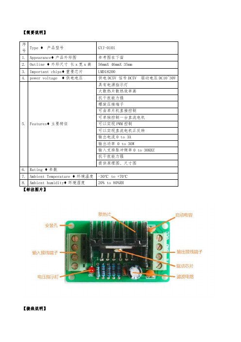
【简要说明】序号Type ♦产品型号GYJ-01011.Appearance♦产品外形图参考图在下面2.Outline ♦外形尺寸长x宽x高56mmX 46mmX 35mm3.Important chips♦重要芯片LMD182004.power voltage ♦供电电压供电DC5V 信号DC5V 驱动电压DC10~30V5.Features♦主要特征具有电源指示灯大散热片散热效率高抗干扰能力强螺旋压接端子可由单片机直接控制可单独控制一台直流电机可以实现PWM控制可以实现直流电机正反转输出电流0 to 3A输出功率 0 to 30W输入支持脉冲频率0 to 30KHZ抗干扰能力强提供原理图、尺寸图6.Rating ♦参数7.Ambient Temperature ♦环境温度-30℃ to +70℃8.Ambient humidity♦环境湿度20% to 80%RH【接线说明】说明:方向信号接高电平正转,低电平反转;PWM端接PWM信号可以调速,接高电平正转,接低电平停止。
【应用举例】分两款一款输入是排针,一款输入是端子【原理图】///////////////////简单的直流电机控制程/////////////////#include<reg52.h>#define uchar unsigned char#define uint unsigned int/********************************************************控制位定义********************************************************/sbit fang_xiang=P1^0; // 方向控制位(输入1正转,输入0反转)sbit sha_che=P1^1; // 启停控制位sbit PWM=P1^2; // 速度控制位(输入电平为1时,电机全速运行,当输入PWM信号时可以调速运行)sbit zheng_zhuan=P2^0; // 正转按键sbit fan_zhuan=P2^1; // 反转按键sbit qi_dong=P2^2; // 启动按键sbit ting_che=P2^3; // 刹车按键/********************************************************主函数********************************************************/main(){fang_xiang=1; // 使能控制位sha_che=0; // 方向控制位PWM=1; // 速度控制位(输入电平为1时,电机全速运行,当输入PWM信号时可以调速运行)while(1){fang_xiang=1; // 使能控制位sha_che=0; // 方向控制位PWM=1; // 速度控制位(输入电平为1时,电机全速运行,当输入PWM信号时可以调速运行)}}///////////////////直流电机调速控制程序/////////////////#include <reg52.h> //头文件#define uchar unsigned char //宏定义无符号字符型#define uint unsigned int //宏定义无符号整型uchar b; //中断值uchar N=0; //占空比计数值uchar X=10; //占空比初始值uchar key_up;uchar key_down;/********************************************************控制位定义********************************************************/sbit qi_dong=P2^0;//M1启动sbit ting_zhi=P2^1;//M1停止sbit jia_su=P2^2; //M1加速sbit jian_su=P2^3;//M1减速sbit fang_xiang=P1^0; // 方向控制位(输入1正转,输入0反转)sbit sha_che=P1^1; // 启停控制位sbit PWM=P1^2; // 速度控制位(输入电平为1时,电机全速运行,当输入PWM信号时可/*************************************************************************/void get_key(void)//按键扫描函数{while(jia_su==0)//按键加计数标志{key_up=1;}while(jian_su==0)//按键减计数标志{key_down=1;}}/*************************************************************************/ void timer0( ) interrupt 1 //定时器0工作方式1{TH0=(65536-1)/256; //重装计数初值TL0=(65536-1)%256; //重装计数初值b++;get_key();if (key_up==1){if(X!=100)//判断是否计数到9999{X=X+5;//加一key_up=0;}}if (key_down==1){if(X!=0)//判断是否计数到0{X=X-5;//减一key_down=0;}}if(qi_dong==0) {sha_che=0;} // 启动if(ting_zhi==0){sha_che=1;} // 刹车}/*************************************************************************/ void main(){TMOD=0X01; //定时器中断0TH0=(65536-2)/256; //定时时间高八位初值TL0=(65536-2)%256; //定时时间低八位初值EA=1; //开CPU中断ET0=1; //开T/C0中断TR0=1;fang_xiang=1;sha_che=0;while(1) //无限循环{PWM=1; //输出PWM正while(1){b=0;while(!b);if (N==X)PWM=0;if (N==100)break;N++;}N=0;}}#include<reg52.h>#define uchar unsigned char#define uint unsigned int/********************************************************控制位定义********************************************************/sbit fang_xiang=P1^0; // 方向控制位(输入1正转,输入0反转)sbit sha_che=P1^1; // 启停控制位sbit PWM=P1^2; // 速度控制位(输入电平为1时,电机全速运行,当输入PWM信号时可以调速运行)sbit zheng_zhuan=P2^0; // 正转按键sbit fan_zhuan=P2^1; // 反转按键sbit qi_dong=P2^2; // 启动按键sbit ting_che=P2^3; // 刹车按键/********************************************************主函数********************************************************/main(){fang_xiang=1; // 使能控制位sha_che=0; // 方向控制位PWM=1; // 速度控制位(输入电平为1时,电机全速运行,当输入PWM信号时可以调速运行)while(1){if(zheng_zhuan==0)fang_xiang=1;// 正转if(fan_zhuan==0)fang_xiang=0; // 反转if(qi_dong==0)sha_che=0; // 启动if(ting_che==0)sha_che=1; // 刹车}}【PCB图】【图片展示】端子款【图片展示】插针款。
HWJT-08C微机励磁调节器使用说明书(第二版2005年)
第三部分 调节器面板 ........................................................................................................................... 21
一、LED数码管显示 ....................................................................................................................................... 21 二、LCD液晶显示 ........................................................................................................................................... 23 三、LCD液晶操作说明 ................................................................................................................................... 24
目
第一部分 导言ቤተ መጻሕፍቲ ባይዱ
录
一、概述 ........................................................................................................................................................... 3 二、主要特点 ................................................................................................................................................... 4 三、适用范围 ................................................................................................................................................... 4 四、基本功能 ................................................................................................................................................... 4 五、技术数据 ................................................................................................................................................... 5 六、主要技术指标 ........................................................................................................................................... 5 七、使用条件 ................................................................................................................................................... 5
高隔离电压的大功率IGBT驱动芯片TX-KE106产品手册

高隔离电压的大功率IGBT驱动芯片TX-KE106产品手册目录一、概述 (3)二、原理框图 (3)三、电气参数 (3)3.1 极限参数 (3)3.2 驱动特性 (4)3.3 工作条件 (5)3.4 短路保护特性 (5)3.5 对驱动电源Vp要求 (6)四、波形图 (6)4.1 正常驱动波形图 (6)4.2 保护波形图 (6)4.3 说明 (6)五、尺寸结构 (7)5.1 外形尺寸 (7)5.2 管脚说明 (7)六、应用电路说明 (7)6.1 驱动器低压信号侧的连接说明 (7)6.1.1 逻辑电路输入电源Vdd (8)6.1.2 输入信号PWM (8)6.1.3 报警信号/Fault (8)6.1.4 复位信号Reset (8)6.2 与外部驱动电源的连接 (8)6.3 驱动器高压侧的输出连接 (8)6.3.1 驱动器输出功率的计算 (8)6.3.2 与IGBT的连接 (8)6.4 保护参数的设置 (9)6.4.1 短路保护阈值Vn的设置 (9)6.4.2 保护盲区Tblind的设置 (9)6.4.3 软关断时间Tsoft的设置 (9)6.5 驱动芯片测试方法 (10)6.6 典型应用连接图 (10)七、相关产品信息 (10)7.1 TX-PD106(DC-DC高隔离模块电源) (10)7.2 TX-DE106D2 IGBT驱动板 (10)八、常见问题 (11)九、其它说明 (11)TX-KE106 高隔离电压、大电流IGBT驱动器一、概述∙高隔离电压IGBT驱动器,可驱动电压≤4500V的全系列IGBT。
∙输出电流40A,输出电荷40μC,输出功率4.5W。
∙变压器调制模式传递PWM信号。
∙短脉冲抑制功能。
∙工作占空比0-100%。
∙关断时输出为负电平。
∙IGBT的栅极充电和放电速度可分别调节。
∙短路软关断保护,并报警输出。
∙绝缘电压7000V。
二、原理框图三、电气参数3.2 驱动特性除另有指定外,均为在以下条件时测得:Ta=25℃,Vdd=5V,Vp=24V,Fop=30KHz四、波形图4.1 正常驱动波形图4.2 保护波形图4.3 说明工作时,由输入端串入的很窄的正负脉冲均被抑制,提高抗干扰性。
1.8A7..2V的低压H桥驱动芯片

单通道内置功率MOS 全桥驱动驱动前进、后退、停止及刹车功能内置迟滞热效应过热保护功能低导通电阻(0.5Ω/1000mA )最大连续输出电流可达 1.8A,峰值 2.5A 无需外围大滤波电容,只需小贴片电容采用DIP-8、SOP-8封装形式玩具马达驱动电子锁电动牙刷电动茶具OUTAPGNDAGNDOUTBSOP-8X118AH注:最大连续输出电流视散热条件而定。
7.211234876512348765DIP-8X118DOUTAPGNDAGNDOUTBNCINAINBVDDNCINAINBVDD(Ta=25℃)电源电压VCC 2.0~7.2V 控制输入电压VIN 0~VCC V 正、反转输出电流Iout-1500~1500A(Ta=25℃,VCC=3V,RL=15Ω,特殊说明除外。
)电路待机电流I CCST INA=INB=GND/VDD=6V —010A 工作电流I CCINA=H,INB=Lor INA=L,INB=H or INA=H,INB=H/VDD=6V—0.31A高电平输入电压V INH 2.0——V 低电平输入电压V INL ——0.8V 高电平输入电流I INH VIN=3V —520A 低电平输入电流I INL VIN=0V-10—A 下拉电阻R IN—15—KΩPWM 频率—3040KHz输出导通阻抗R ONIo=±1000mA/5V—10.5ΩINA 、INB 内置下拉电阻121520ΩPWM 频率—3040KHz热关断温度点TSD --150--℃热关断温度迟滞TSDH--20--/INA INB OUTA OUTB L L Hi-Z Hi-Z 待命状态H L H L 前进L H L H 后退HHLL刹车m u m u u kPCBINAINB VDDOUTA GND2GND1OUTBC1220uF C4104pF注:在不同的应用中,C1、C2可考虑只装一个:在3V 应用中建议用一个1uF 或以上;在 4.5V 应用中建议用一个 4.7uF 或以上,均为使用贴片电容;在6V 应用中建议用一个大电容220uF+100nF 贴片电容;C2均靠近IC 之VDD 管脚放置且电容的负极和IC 的GND 端之间的连线也需尽量短。
双全桥步进电机专用驱动芯片L298中文资料

双全桥步进电机专用驱动芯片L298中文资料
双全桥步进电机专用驱动芯片( Dual Full-Bridge Driver )L298中文资料
L298N 为SGS-THOMSON Microelectronics 所出产的双全桥步进电机专用驱动芯片( Dual Full-Bridge Driver ) ,内部包含4信道逻辑驱动电路,是一种二相
和四相步进电机的专用驱动器,可同时驱动2个二相或1个四相步进电机,内含二个H-Bridge 的高电压、大电流双全桥式驱动器,接收标准
TTL逻辑准位信号,可驱动46V、2A以下的步进电机,且可以直接透过电源来调节输出电压;此芯片可直接由单片机的IO端口来提供模拟时序信号,
但在本驱动电路中用L297 来提供时序信号,节省了单片机IO 端口的使用。
L298N 之接脚如图9 所示,Pin1 和Pin15 可与电流侦测用电阻连接来控制负载的电路; OUTl、OUT2 和OUT3、OUT4 之间分别接2 个步进电机;input1~input4 输入控制电位来控制电机的正反转;Enable 则控制电机停转。
图9 L298引脚图
图10 L298 内部逻辑图
L298 ABSOLUTE MAXIMUM RATINGS 绝对最大额定值:
L298 PIN FUNCTIONS (refer to the block diagram) 引脚功能(请参阅框图):
L298 ELECTRICAL CHARACTERISTICS(VS=42V;VSS=5V,Tj=25℃; unless otherwise specified)电气特性:
图11 L298 外形图。
L298双H桥直流电机驱动板指导手册

L298双H桥直流电机驱动板指导手册V0.1一、产品参数:1、驱动芯片:L298N双H桥直流电机驱动芯片2、驱动部分端子供电范围Vs:+5V~+35V ;如需要板内取电,则供电范围Vs:+7V~+35V3.驱动部分峰值电流Io:2A4.逻辑部分端子供电范围Vss:+5V~+7V(可板内取电+5V)5.逻辑部分工作电流范围:0~36mA6.控制信号输入电压范围:低电平:-0.3V≤Vin≤1.5V高电平:2.3V≤Vin≤Vss7.使能信号输入电压范围:低电平:-0.3≤Vin≤1.5V(控制信号无效)高电平:2.3V≤Vin≤Vss(控制信号有效)8.最大功耗:20W(温度T=75℃时)9.存储温度:-25℃~+130℃10.驱动板尺寸:55mm*49mm*33mm(带固定铜柱和散热片高度)11.驱动板重量:33g12.其他扩展:控制方向指示灯、逻辑部分板内取电接口。
二、电路原理图三、使用说明:1、直流电机的驱动:// 硬件连接:P1.0----IN1// P1.1----IN2// P1.2----ENA// 直流电机两端分别接OUT1和OUT2,// 电机驱动电压根据所接电机而定,驱动板芯片逻辑电压为+5V// 维护记录:2012.2.8 双龙电子科技//*****************************************************************// #include<reg52.h>sbit IN1=P1^0;sbit IN2=P1^1;sbit ENA=P1^2;void delay(unsigned int z);void delay_us(unsigned int aa);/*******************主函数**************************/void main(){while(1){unsigned int i,cycle=0,T=2048;IN1=1; //正转IN2=0;for(i=0;i<200;i++){delay(10);//PWM占空比为50%,修改延时调整PWM脉冲ENA=~ENA;}IN1=0; //反转IN2=1;for(i=0;i<100;i++){delay(20);//PWM占空比为50%,修改延时调整PWM脉冲ENA=~ENA;}IN1=1; //自动加速正转IN2=0;while(cycle!=T){ ENA=1;delay_us(cycle++);ENA=0;delay_us(T-cycle);}IN1=0; //自动减速反转IN2=1;while(cycle!=T)该步进电机为四相步进电机,采用单极性直流电源供电。
介绍几种电机驱动芯片

介绍几种电机驱动芯片[作者:佚名转贴自:本站原创点击数:1493 更新时间:2005-4-22 文章录入:白桦]减小字体增大字体在自制机器人的时候,选择一个合适的驱动电路也是非常重要的,本文详细介绍了几种常用的机器人驱动芯片。
介绍几种机器人驱动芯片(注:本文已经投稿至《电子制作》)在自制机器人的时候,选择一个合适的驱动电路也是非常重要的。
最初,通常选用的驱动电路是由晶体管控制继电器来改变电机的转向和进退,这种方法目前仍然适用于大功率电机的驱动,但是对于中小功率的电机则极不经济,因为每个继电器要消耗20~100mA的电力。
当然,我们也可以使用组合三极管的方法,但是这种方法制作起来比较麻烦,电路比较复杂,因此,我在此向大家推荐的是采用集成电路的驱动方法:马达专用控制芯片LG9110芯片特点:低静态工作电流;宽电源电压范围:2.5V-12V ;每通道具有800mA 连续电流输出能力;较低的饱和压降;TTL/CMOS 输出电平兼容,可直接连CPU ;输出内置钳位二极管,适用于感性负载;控制和驱动集成于单片IC 之中;具备管脚高压保护功能;工作温度:0 ℃-80 ℃。
描述:LG9110 是为控制和驱动电机设计的两通道推挽式功率放大专用集成电路器件,将分立电路集成在单片IC 之中,使外围器件成本降低,整机可靠性提高。
该芯片有两个TTL/CMOS 兼容电平的输入,具有良好的抗干扰性;两个输出端能直接驱动电机的正反向运动,它具有较大的电流驱动能力,每通道能通过750 ~800mA 的持续电流,峰值电流能力可达1.5 ~2.0A ;同时它具有较低的输出饱和压降;内置的钳位二极管能释放感性负载的反向冲击电流,使它在驱动继电器、直流电机、步进电机或开关功率管的使用上安全可靠。
LG9110 被广泛应用于玩具汽车电机驱动、步进电机驱动和开关功率管等电路上。
管脚定义:1 A 路输出管脚、2和3 电源电压、4 B 路输出管脚、5和8 地线、6 A 路输入管脚、7 B 路输入管脚2、恒压恒流桥式1A驱动芯片L293图2是其内部逻辑框图图3是其与51单片机连接的电路原理图L293是著名的SGS公司的产品,内部包含4通道逻辑驱动电路。
液晶电子工业有限公司产品数据手册:液晶电子电机启动器套件、联击器、热过载保护传感器说明书
T h e i n f o r m a t i o n p r o v i d e d i n t h i s d o c u m e n t a t i o n c o n t a i n s g e n e r a l d e s c r i p t i o n s a n d /o r t e c h n i c a l c h a r a c t e r i s t i c s o f t h e p e r f o r m a n c e o f t h e p r o d u c t s c o n t a i n e d h e r e i n .T h i s d o c u m e n t a t i o n i s n o t i n t e n d e d a s a s u b s t i t u t e f o r a n d i s n o t t o b e u s e d f o r d e t e r m i n i n g s u i t a b i l i t y o r r e l i a b i l i t y o f t h e s e p r o d u c t s f o r s p e c i f i c u s e r a p p l i c a t i o n s .I t i s t h e d u t y o f a n y s u c h u s e r o r i n t e g r a t o r t o p e r f o r m t h e a p p r o p r i a t e a n d c o m p l e t e r i s k a n a l y s i s , e v a l u a t i o n a n d t e s t i n g o f t h e p r o d u c t s w i t h r e s p e c t t o t h e r e l e v a n t s p e c i f i c a p p l i c a t i o n o r u s e t h e r e o f .N e i t h e r S c h n e i d e r E l e c t r i c I n d u s t r i e s S A S n o r a n y o f i t s a f f i l i a t e s o r s u b s i d i a r i e s s h a l l b e r e s p o n s i b l e o r l i a b l e f o r m i s u s e o f t h e i n f o r m a t i o n c o n t a i n e d h e r e i n .Product data sheetCharacteristicsLR9D32KITD18BDTESYS motor starter kit, LC1D18BD contactor,LR9D32 thermal overload relayProduct availability: Non-Stock - Not normally stocked in distribution facility MainRange TeSysProduct or componenttypeMotor starterContactor application Motor controlResistive loadUtilisation category AC-4AC-1AC-3Poles description3PPower pole contactcomposition3 NO[Ue] rated operationalvoltagePower circuit <= 690 V AC 25...400 HzPower circuit <= 300 V DC[Ie] rated operationalcurrent18 A 140 °F (60 °C)) <= 440 V AC AC-3 power cir-cuit32 A 140 °F (60 °C)) <= 440 V AC AC-1 power circuit Motor power kW4 KW 220...230 V AC 50/60 Hz AC-3)7.5 KW 380...400 V AC 50/60 Hz AC-3)9 KW 415...440 V AC 50/60 Hz AC-3)10 KW 500 V AC 50/60 Hz AC-3)10 KW 660...690 V AC 50/60 Hz AC-3)4 kW 400 V AC 50/60 Hz AC-4)Motor power HP (UL /CSA)1 Hp 115 V AC 50/60 Hz 1 phase3 Hp 230/240 V AC 50/60 Hz 1 phase5 Hp 200/208 V AC 50/60 Hz 3 phase5 Hp 230/240 V AC 50/60 Hz 3 phase10 Hp 460/480 V AC 50/60 Hz 3 phase15 hp 575/600 V AC 50/60 Hz 3 phaseControl circuit type DC standard[Uc] control circuit volt-age24 V DCAuxiliary contact com-position1 NO + 1 NC[Uimp] rated impulsewithstand voltage6 kV IEC 60947Overvoltage category III[Ith] conventional freeair thermal current10 A 140 °F (60 °C) signalling circuit32 A 140 °F (60 °C) power circuitIrms rated making ca-pacity140 A AC signalling circuit IEC 60947-5-1250 A DC signalling circuit IEC 60947-5-1300 A 440 V power circuit IEC 60947Rated breaking capacity300 A 440 V power circuit IEC 60947[Icw] rated short-timewithstand current145 A 104 °F (40 °C) - 10 s power circuit240 A 104 °F (40 °C) - 1 s power circuit40 A 104 °F (40 °C) - 10 min power circuit84 A 104 °F (40 °C) - 1 min power circuit100 A - 1 s signalling circuit120 A - 500 ms signalling circuit140 A - 100 ms signalling circuitAssociated fuse rating10 A gG signalling circuit IEC 60947-5-150 A gG <= 690 V type 1 power circuit35 A gG <= 690 V type 2 power circuitAverage impedance 2.5 mOhm - Ith 32 A 50 Hz power circuit[Ui] rated insulation volt-agePower circuit 690 V IEC 60947-4-1Power circuit 600 V CSAPower circuit 600 V ULSignalling circuit 690 V IEC 60947-1Signalling circuit 600 V CSASignalling circuit 600 V ULElectrical durability 1.65 Mcycles 18 A AC-3 <= 440 V1 Mcycles 32 A AC-1 <= 440 VPower dissipation perpole2.5 W AC-10.8 W AC-3Safety cover WithMounting support PlateRailStandards CSA C22.2 No 14EN 60947-4-1EN 60947-5-1IEC 60947-4-1IEC 60947-5-1UL 508Product certifications LROS (Lloyds register of shipping)DNVGLRINABVCCCULCSAGOSTConnections - terminals Control circuit screw clamp terminals 1 0.00…0.01 in² (1…4 mm²)flexible without cable endControl circuit screw clamp terminals 2 0.00…0.01 in² (1…4 mm²)flexible without cable endControl circuit screw clamp terminals 1 0.00…0.01 in² (1…4 mm²)flexible with cable endControl circuit screw clamp terminals 2 0.00…0.00 in² (1…2.5 mm²)flexible with cable endControl circuit screw clamp terminals 1 0.00…0.01 in² (1…4 mm²)solid without cable endControl circuit screw clamp terminals 2 0.00…0.01 in² (1…4 mm²)solid without cable endPower circuit screw clamp terminals 1 0.00…0.01 in²(1.5…6 mm²)flexible without cable endPower circuit screw clamp terminals 2 0.00…0.01 in²(1.5…6 mm²)flexible without cable endPower circuit screw clamp terminals 1 0.00…0.01 in²(1…6 mm²)flexible with cable endPower circuit screw clamp terminals 2 0.00…0.01 in²(1…4 mm²)flexible with cable endPower circuit screw clamp terminals 1 0.00…0.01 in²(1.5…6 mm²)solid without cable endPower circuit screw clamp terminals 2 0.00…0.01 in²(1.5…6 mm²)solid without cable endTightening torque Power circuit 15.05 lbf.in (1.7 N.m) screw clamp ter-minals flat Ø 6 mmPower circuit 15.05 lbf.in (1.7 N.m) screw clamp ter-minals Philips No 2Control circuit 15.05 lbf.in (1.7 N.m) screw clampterminals flat Ø 6 mmControl circuit 15.05 lbf.in (1.7 N.m) screw clamp ter-minals Philips No 2Operating time53.55...72.45 ms closing16...24 ms openingSafety reliability level B10d = 1369863 cycles contactor with nominal loadEN/ISO 13849-1B10d = 20000000 cycles contactor with mechanicalload EN/ISO 13849-1Mechanical durability30 McyclesMaximum operating rate3600 cyc/h 140 °F (60 °C)Relay application Motor protectionPhase failure sensitivity Phase difference > 40% 3 s IEC 60947-4-1 ComplementaryCoil technology With integral suppression deviceControl circuit voltage limits Drop-out 0.1...0.25 Uc DC 140 °F (60 °C))Operational 0.7...1.25 Uc DC 140 °F (60 °C))Time constant28 msInrush power in W 5.4 W 68 °F (20 °C))Hold-in power consumption in W 5.4 W 68 °F (20 °C)Auxiliary contacts type Mechanically linked 1 NO + 1 NC IEC 60947-5-1Mirror contact 1 NC IEC 60947-4-1Signalling circuit frequency25...400 HzMinimum switching current5 mA signalling circuitMinimum switching voltage17 V signalling circuitNon-overlap time 1.5 Ms on de-energisation between NC and NO contact1.5 ms on energisation between NC and NO contactInsulation resistance> 10 MOhm signalling circuitContact compatibility M4Motor power range4…6 KW 200…240 V 3 phase7…11 KW 380…440 V 3 phase7…11 kW 480…500 V 3 phaseMotor starter type Direct on-line contactorContactor coil voltage24 V DC standardThermal overload class Class 5 (30)Thermal protection adjustment range 6.4…32 AMaximum power consumption in W300 mWMounting support Under contactorPlate, with specific accessoriesRail, with specific accessories[Ue] rated operational voltage690 V power circuit660 V signalling circuit[Ui] rated insulation voltage Power circuit 1000 VSignalling circuit 690 VTripping threshold 1.25 In IEC 60947-4-1Control type Red push-button stop and manual resetWhite 2 microswitches adjustable trip classRed knob automatic resetGrey dial full-load current adjustmentTime range 1.5...4 min - automatic reset time[Ith] conventional free air thermal current5 A signalling circuitAssociated fuse rating5 A gG signalling circuit5 A BS signalling circuit[Uimp] rated impulse withstand voltage6 kVIP degree of protection Front face IP20 IEC 60529Front face IP20 VDE 0106Mechanical robustness Vibrations 10...150 Hz 6 Gn) IEC 60068-2-6Shocks 11 ms 15 gn) IEC 60068-2-7Connections - terminals Control circuit screw clamp terminals 1 0.00 in² (2.5 mm²) solid or flexible - with-out cable endPower circuit screw clamp terminals 1 0.02 in² (16 mm²) solid or flexible - withoutcable endTightening torque Control circuit 0.8 N.m screw clamp terminalsPower circuit 3.1 N.m screw clamp terminalsEnvironmentIP degree of protection IP20 front face IEC 60529Protective treatment TH IEC 60068-2-30Pollution degree3Ambient air temperature for operation23…140 °F (-5…60 °C)-40…158 °F (-40…70 °C) at UcPermissible ambient air temperature around the de-viceOperating altitude9842.52 ft (3000 m) withoutMechanical robustness Vibrations contactor open2 Gn, 5...300 HzVibrations contactor closed4 Gn, 5...300 HzShocks contactor open10 Gn for 11 msShocks contactor closed15 Gn for 11 msHeight 3.03 in (77 mm)Width 1.77 in (45 mm)Depth 3.74 in (95 mm)Net weight 1.08 lb(US) (0.49 kg)Standards UL 60947-4-1IEC 60947-4-1CSA C22.2GB 14048.4Product certifications CSACCCTÜVCULusAmbient air temperature for operation-13…158 °F (-25…70 °C) IEC 60255-8Ambient air temperature for storage-76…176 °F (-60…80 °C)Ambient air temperature for storage-67…176 °F (-55…80 °C)Operating altitude6561.68 ft (2000 m) without deratingFire resistance1562 °F (850 °C) IEC 60695-2-1Flame retardance V1 UL 94Electromagnetic compatibility Surge withstand 2 kV common mode IEC 61000-4-5Resistance to electrostatic discharge 8 kV IEC 61000-4-2Immunity to radiated radio-electrical interference 10 V/m IEC 61000-4-3Immunity to fast transients 2 kV IEC 61000-4-4Dielectric strength6 kV 50 Hz IEC 60255-5Height 2.85 in (72.5 mm)Width 1.77 in (45 mm)Depth 3.15 in (79.9 mm)Net weight0.40 lb(US) (0.18 kg)Ordering and shipping detailsCategory22350 - LR9D AND TESYS D STARTER KITSDiscount Schedule I12Package weight(Lbs)0.80 kg (1.76 lb(US))Returnability YesCountry of origin CNOffer SustainabilityEU RoHS Directive Under investigation。
【数据手册】HSJ522W,韦根接口,M1读卡模块应用指南
HSJ522W读卡模块应用指南广州慧斯佳智能科技有限公司修订历史概述HSJ522系列读卡模块简介HSJ522系列模块是基于13.56MHz频率的Mifare卡读写模块,符合ISO14443A标准,可支持Mifare1 S50、Mifare1 S70、Mifare Light、Mifare UltraLight、Mifare Pro。
TX522系列Mifare读写模块具有易用、高可靠、多种接口、体积小等特点,可帮助用户方便、快捷地将当今最流行的非接触式IC卡技术融入到系统中,提高产品的档次。
HSJ522W为自动寻卡模块,上电后无需向模块发送任何命令,只要有卡靠近模块就能主动通过韦根发送卡号。
HSJ522W是一个简单的韦根接口只读卡号模块。
可设置为韦根34或韦根26两种输出格式。
如图0.1所示为HSJ522W读卡模块。
产品特性体积小巧、简单、易用、性价比高支持各种mifare卡及其兼容卡读写卡距离远(根据应用可达10-100mm)模块内部具有看门狗,永不死机接受批量客户定制产品应用电子感应门锁门禁系统、办公/家庭安防、身份识别、出入管理、公司考勤防伪系统、身份识别票证以及其他相关应用图0.1 HSJ522W读卡模块目录概述 (1)HSJ522系列读卡模块简介 (1)产品特性 (1)产品应用 (1)1. 硬件描述 (1)1.1引脚描述 (1)1.2典型电路 (2)1.3技术参数 (2)1.4极限参数 (2)1.5直流特性 (3)1.6封装及机械尺寸 (3)2. 接口方式及典型应用 (5)2.1返回卡号说明 (5)3. 数据通讯协议 (6)3.1韦根接口协议 (6)4. 免责声明 (8)4.1开发预备知识 (8)4.2EMI 与EMC (8)4.3修改文档的权利 (8)4.4ESD静电放电保护 (8)5. 销售信息 (9)1. 硬件描述1.1 引脚描述图1.1 HSJ522系列模块管脚图表1.1 外接天线接口J1J1为模块与天线的接口,对于天线一体化(带后缀T )的模块,如果用户使用模块上的PCB 印制天线,则可以不使用该接口;对于非天线一体化(不带后缀T )的模块,用户要通过该接口来连接天线。
北京落木源 IGBT驱动器TX-KE107产品手册

二单元高频大功率 IGBT驱动芯片TX-KE107产品手册目录一、概述 (3)二、原理框图 (3)三、电气参数 (3)3.1 极限参数 (3)3.2 驱动特性 (4)3.3 工作条件 (5)3.4 短路保护特性 (5)四、波形图 (5)4.1 正常驱动波形图 (5)4.2 保护波形图 (5)五、尺寸结构 (6)5.1 外形尺寸(俯视图和前视图) (6)5.2 引脚说明 (6)六、应用电路说明 (7)6.1 驱动器低压信号侧的设置和连接 (7)6.1.1 输入电源Vdd (7)6.1.2 工作模式输入信号Mode (7)6.1.3 死区时间 (8)6.1.4 PWM输入信号INA和INB (8)6.1.5 故障输出信号Fault/ (8)6.1.6 复位信号Reset (8)6.2 驱动器高压侧的输出连接 (8)6.2.1 驱动输出功率的计算 (8)6.2.2 滤波电容 (8)6.2.3 与IGBT的连接 (9)6.3 保护参数的设置 (9)6.3.1 短路保护响应时间Tblind(盲区)的调节 (9)6.3.2 驱动保护电压阈值Vn的设置 (9)6.3.3 欠压保护 (9)6.4 驱动芯片测试方法 (9)6.5 典型应用图 (10)七、相关产品信息 (10)7.1 KA103 单管MOSFET驱动器 (10)八、常见问题 (10)九、其它说明 (10)TX-KE107高频大功率MOSFET 2单元驱动器一、概述∙ 二单元半桥隔离驱动器,适应于大功率MOSFET ∙ 工作频率高达300KHz,输出功率2x3W ∙ 死区控制∙ 自带隔离的DC/DC 电源 ∙ 驱动输出电流30A∙ 变压器调制模式传递PWM 信号,工作占空比0-100% ∙ 快速的短路检测和关断保护,同时报警 ∙ 绝缘电压4.5KV二、原理框图三、电气参数 3.1 极限参数符号 名称极限参数 单位 VdcDC/DC 输入电源电压13VVdd 逻辑电路供电电压 13 VVi 逻辑信号输入电压(INA,INB,Mode,Reset) 15 VIfault 报警信号输出电流 15 mAPo 2路输出总功率 6 WIo 驱动器输出瞬态峰值电流 ±30 AViso 输入输出绝缘电压(50Hz/1min) 4.5 KVRg 最小栅极电阻 1 ΩTdead 最小死区时间 0.33 μsFop 最大开关频率 300 KHz3.2 驱动特性除另有指定外,均为在以下条件时测得:Ta=25℃,Vdd=12V,Vdc=12V,Fop=150KHz参数符号 测试条件 最小值 典型值 最大值 单位 DC/DC输入电源电压 Vdc 11.4 12 12.6 VDC/DC输入电流 Idc 空载 160mA 输出2x4W 1000逻辑电源电压 Vdd 11.4 12 13 V 逻辑电源电流 Idd 8 mA输入脉冲信号电压 Vs 高电平 7.2 12 15V 低电平 -1 1.5 4.8输入脉冲信号电流 Is 2 mA输出电压 Vo+ 12.5V Vo- -12.5输出电流 Io+Ton=1μS,δ=0.0120A Io- -20栅极电阻 Rg 用户设置 1 Ω输出总电荷 Qout 20 μC工作频率 Fop 0 300 KHz输出功率 Po 每路 3 W占空比 δ 0 100 %上升延迟 Trd 500nS 下降延迟 Tfd 550死区时间 Tdead 用户设置 0.33 μS绝缘电压 Viso 50Hz/1 min 4.5 KVrms输入输出耦合电容 Cps 10 pF输出耦合电容 Css A路与B路间 10 pF共模瞬态抑制 CMR 50 KV/μS3.3 工作条件环境温度 符号 测 试 条 件最小值 典型值 最大值 单位 工作温度 Top 常规 -40 85 ℃ 存储温度Tst-60140℃3.4 短路保护特性参 数 符号 测 试 条 件最小值典型值最大值 单位保护动作阈值 Vn用户设置,最大值为缺省值10 V 响应时间 Tblind 用户设置,最小值为缺省值 0.2 μS 故障后重启时间 Treset 50 60 ms 报警信号延迟 Tfault 1 μS 报警端常态输出11 V 报警输出低电平最大值在拉电流10mA 时2 V 报警端输出拉电流 Ifault 低电平报警信号10 20 mA 复位正脉冲信号 电压、电流和宽度Vreset7.2 12 15 V Ireset 2 mA Trw0.524μS3.5 对输入电源的要求(除另有指定外,均为在以下条件时测得:Ta=25℃,Vdc=15V)参数 符号 测试条件最小值 典型值 最大值 单位 输入电压Vdc11.5 12 13 V 输入电源电流Idc空载160mA输出2x3W 时745 mA 输入电源功率Pi驱动输出3W 时,典型值为实际消耗,最大值为有裕量输入要求912.6W四、波形图4.1 正常驱动波形图很窄的正负脉冲均被抑制,提高抗干扰性。
LSA PMR 320 8-pole 铁路应用电机维护手册说明书
LSA PMR 320 Alternator for rail application - 8-poleInstallation and maintenance22021.06 / dElectric Power Generation Installation and maintenanceLSA PMR 320Alternator for rail application - 8-pole5785 en -This manual concerns the alternator which you have just purchased.We wish to draw your attention to the contents of this maintenance manual. SAFETY MEASURESBefore using your machine for the first time, it is important to read the whole of this installation and maintenance manual.All necessary operations and interventions on this machine must be performed by a qualified technician.Our technical support service will be pleased to provide any additional information you may require.The various operations described in this manual are accompanied by recommenda-tions or symbols to alert the user to potential risks of accidents. It is vital that you unders-tand and take notice of the following warning symbols.of damaging or destroying the machine or surrounding equipment.personnel.Warning symbol for electrical danger topersonnel.SAFETY INSTRUCTIONS We wish to draw your attention to the following 2 safety measures which must be complied with:a) During operation, do not allow anyone to stand in front of the air outlet guards, in case anything is ejected from them.b) Do not allow children younger than 14 to go near the air outlet guards.A set of self-adhesive stickers depicting the various warning symbols is included with this maintenance manual. They should be positioned as shown in the drawing below once the machine has been fully installed.WARNINGThe alternators must not be put into service until the machines in which they are to be incorporated have been declared compliant with EC Directives plus any other directives that may be applicable.This manual is to be given to the end user.The range of electric alternators and their derivatives, manufactured by us or on our behalf, comply with the technical requirements of the customs Union directives (EAC).© - We reserve the right to modify the characteristics of this product at any time in order to incorporate the latest technological developments. The information contained in this document may therefore be changed without notice.This document may not be reproduced in any form without prior authorisation.All brands and models have been registered and patents applied for.Electric Power Generation Installation and maintenance5785 en -2021.06 / dLSA PMR 320Alternator for rail application - 8-poleCONTENTS1 - RECEIPT (4)1.1 - Standards and safety measures (4)1.2 - Inspection (4)1.3 - Identification (4)1.4 - Storage (4)1.5 - Applications (4)1.6 - Usage restrictions (4)2 - TECHNICAL CHARACTERISTICS (5)2.1 - Electrical characteristics (5)2.2 - Mechanical characteristics (5)3 - INSTALLATION (5)3.1 - Assembly (5)3.2 - Checks prior to first use (5)3.3 - Terminal connection diagrams (6)3.4 - Commissioning (7)4 - SERVICING - MAINTENANCE (8)4.1 - Safety measures (8)4.2 - Routine maintenance (8)4.3 - Bearings (9)4.4 - Mechanical defects (9)4.5 - Electrical faults (9)4.6 - Dismantling, reassembly (10)4.7 - Table of characteristics (10)5 - SPARE PARTS (11)5.1 - First maintenance parts (11)5.2 - Technical support service (11)5.3 - Accessories (11)5.4 - Exploded view, parts list and tightening torque (12)Disposal and recycling instructions342021.06 / dElectric Power Generation Moteurs Leroy-Somer - Boulevard Marcellin Leroy,CS 10015 - 16915 Angoulême Cedex 9 - FranceInstallation and maintenanceLSA PMR 320Alternator for rail application - 8-pole5785 en -1 - RECEIPT1.1 - Standards and safety measuresOur alternators comply with most international standards.See the EC Declaration of Incorporation on the last page.1.2 - InspectionOn receipt of your alternator, check that it has not suffered any damage in transit. If there are obvious signs of knocks, contact the transporter (you may be able to claimon their insurance) and after a visualcheck, turn the machine by hand to detect any malfunction.1.3 - IdentificationThe alternator is identified by means of a nameplate fixed on the machine (see drawing).Make sure that the nameplate on the machine conforms to your order.So that you can identify your alternator quickly and accurately, we suggest you fill in its specifications on the nameplate below.1.4 - StoragePrior to commissioning, machines should be stored:- away from humidity (< 90%); after a long period of storage, check the machine insulation. To prevent the bearings from becoming marked, do not store in an environment with significant vibration .1.5 - ApplicationThis alternator is mainly designed to produce electricity in the context of applications involving the use of generators.1.6 - Usage restrictionsUse of the machine is restricted to operating conditions (environment, speed, voltage, power, etc) compatible with the characteri-stics indicated on the nameplate..2021.06 / d Electric Power Generation Installation and maintenanceLSA PMR 320Alternator for rail application - 8-pole5785 en -2 - TECHNICAL CHARACTERISTICS2.1 - Electrical characteristicsThis alternator is a machine with permanent magnets, wound as full pitch, 12-wire, with class H insulation.- 4 PT 1000 stator temperature detection sensors connected to a fast-on connector 2.2 - Mechanical characteristics- Steel frame- Steel DE and NDE shields- Regreasable insulated ball bearings- Mounting arrangement: two-bearing with SAE flange and standard cylindrical shaft extension- Water-cooled enclosed machine- Degree of protection: IP 693 - INSTALLATIONPersonnel undertaking the various operations indicated in this section must wear personal protective equipment appropriate for mechanical and electrical hazards.All mechanical handling operations must be undertaken using suitable equipment and the machine must be ho-rizontal. Check how much the machine weighs before choosing the lifting tool. During this operation, do not allow anyone to stand under the load.• HandlingThe generously-sized lifting eyes are for handling the alternator only. They must not be used to lift the genset. The choice of lifting hooks or handles should be determined by the shape of the lifting eyes. Choose a lifting system which respects the integrity and the environment of the machine.During this operation, do not allow anyone to stand under the load.• Double-bearing coupling- Semi-flexible couplingCareful alignment of the machines is recommended, checking that the lack of concentricity and parallelism of both parts of the coupling do not exceed 0.1 mm.This alternator has been balanced with a 1/2 key.• LocationThe room where the alternator is placed must be ventilated to ensure that the ambient temperature cannot exceed the data on the nameplate.3.2 - Checks prior to first usealternator, new or otherwise, be operated if the insulation is less than 1 megohm for the stator.52021.06 / d Electric Power Generation Installation and maintenanceLSA PMR 320Alternator for rail application - 8-pole5785 en -• Mechanical checksBefore starting the machine for the first time, check that:- all fixing screws are tight, and there are no leaks from the water inlet and outlet,- the length of screw and the tightening torque are correct,- the protective grille is correctly in place,- the standard direction of rotation is clock-wise as seen from the drive end (phase rotation in order 1 - 2 - 3).For anti-clockwise rotation, swap 2 and 3.3.3 - Terminal connection diagramsAny intervention on the alternator terminals during checks should be performed with the machine stopped.In no case should the internal connections in the terminal box be subjected to stresses due to cables connected by the user.• Three-phase 12-wire672021.06 / dElectric Power Generation Installation and maintenanceLSA PMR 320Alternator for rail application - 8-pole5785 en -Electrical installations must comply with the current legislation in force in the country of use.Check that:- the residual circuit-breaker conforms to legislation on protection of personnel, in force in the country of use, and has been correctly installed on the alternator power output as close as possible to the alternator.- any protection devices in place have not been tripped.- the connections between the alternator and the cabinet are made in accordance with the connection diagram.- there is no short-circuit phase-phase or phase-neutral between the alternator output terminals and the cabinet.- the machine should be connected with the busbar separating the terminals as shown in the terminal connection diagram.- the earth terminal is connected to the frame.The connections inside the terminal box must never be subjected to stress due tocables connected by the user.Diameter M6M8M10M12Torque 4 Nm10 Nm 20 Nm 35 NmTolerance± 15%3.4 - CommissioningThe machine can only be started up and used if the installation is in accordance with the regulations and instructions defined in this manual.The machine is tested at the factory.When first used with no load, see table section 4.7.2021.06 / d Electric Power Generation Installation and maintenanceLSA PMR 320Alternator for rail application - 8-pole5785 en -4 - SERVICING - MAINTENANCE4.1 - Safety measuresServicing or troubleshooting must be carried out strictly in accordance with instructions so as to avoid the risk of accidents and to maintain the machine inits original state.alternator should be undertaken by personnel trained in the commissioning, servicing and maintenance of electrical and mechanical components, who must wear personal protective equipment appropriate for mechanical and electrical hazards.Before any intervention on the machine, ensure that it cannot be started by a manual or automatic system and that you have understood the operating principles of thesystem.Warning: during and after running, the alternator will reach temperatures hot enough to cause injury, such as burns. 4.2 - Routine maintenance• Checks after start-upAfter approximately 20 hours of operation, check that all fixing screws on the machine are still tight, plus the general state of the machine and the various electrical connections in the installation.• Electrical servicingCommercially-available volatile degreasing agents can be used.Do not use: trichlorethylene, perchlo-rethylene, trichloroethane or any alkalineproducts.These operations must be performed at a cleaning station, equipped with a vacuum system that collects and flushes out the products used.The insulating components and the impregnation system are not at risk of damage from solvents. Avoid letting the cleaning product run inside the machine by the terminal box.Apply the product with a brush, sponging frequently to avoid accumulation in the housing. Dry the winding with a dry cloth. Let any traces evaporate before before closing the terminal box.• Mechanical servicingCleaning the machine using water or a high-pressure washer is permitted, provided it is done in accordance with EN 60529.Degreasing: use a brush and detergent (suitable for paintwork).Dusting: use an air gun.After cleaning the alternator, it is essential to check the winding insulation (see sections 3.2 and 4.5).8Electric Power Generation Installation and maintenance2021.06 / d5785 en -LSA PMR 320Alternator for rail application - 8-pole4.3 - BearingsThe bearings are regreasable Life of the grease = 700 hours or 1 yearGrease: Mobil Polyrex EM NLGI2Amount of grease at each regreasing = 51 g minimum• Checking the windingYou can check the winding insulation by performing a high voltage test.9102021.06 / dElectric Power Generation Installation and maintenanceLSA PMR 320Alternator for rail application - 8-pole5785 en -operation should only be carried out in an approved workshop or in our factory, otherwise the warranty may be invalidated.Check how much the machine weighs before choosing the lifting method. • Tools requiredTo fully dismantle the machine, we recommend using the tools listed below:- 1 ratchet spanner + extension - 1 torque wrench- 1 set of flat spanners: 7, 8, 10, 12 mm- 1 socket set: 8, 10, 13, 16, 18, 21, 22, 24 mm- 1 Allen key: size 5 (eg. Facom: ET5), size 6 (ET6), size 10 (ET10, size 14 (ET14)- 1 T20 and T30 TORX bit - 1 puller (U35)/(U32/350)• Screw tightening torque See section 5.4.• Access to connectionsThe terminals are accessed directly by removing the terminal box cover (136). • Replacing the DE bearing- Remove the alternator from the genset.- Remove the air outlet grille (33).- Remove the screws holding the bearing retainer (68) in place.- Remove the screws holding the DE shield (30) on the frame.- Pull on the DE shield to separate it from the frame with a suitable tool (which we can provide).- The rotor will stick to the stator, and is likely to make a noise.- Remove the circlips (67) from the DE bearing (60).- Push the bearing retainer (68) back along the shaft.- Pull out the DE bearing (60).- Fit the new DE bearing, taking care not to overheat it.- Refit the DE shield (30) by repeating these steps in reverse order.- Grease and fit a new seal.• Replacing the NDE bearing- Remove the alternator from the genset.- Remove the cover plate from the NDE shield (73).- Open the terminal box (132).- Undo the power connections (124) and sensors (197).- Detach the clamps holding the wiring in the terminal box and the NDE shield (36).- Undo the screws holding the bearing retainer (68) in place.- Remove the screws holding the shield (36) on the frame.- Remove the DE shield with a suitable tool (which we can provide).- The rotor will stick to the stator, and is likely to make a noise.- Push the bearing retainer (68) back along the shaft.- Pull out the NDE bearing (60).- Fit the new NDE bearing, taking care not to overheat it.- Refit the NDE shield (36) by repeating these steps in reverse order.4.7 - Table of characteristicsTable of average values:Alternator - 8-pole - 800 rpm to 2000 rpm All values are given to within ± 10% and may be changed without prior notification (for exact values, consult the test report).• Resistance at 20°C - L/N stator:0.0245 ohms• No-load voltage as a function of • Total weight: 900 kg - Rotor: 330 kg112021.06 / dElectric Power Generation Installation and maintenanceLSA PMR 320Alternator for rail application - 8-pole5785 en -5.2 - Technical support serviceOur technical support service will be pleased to provide any additional information you may require.For all spare parts orders or technical support requests, send your request to *********************************nearest contact, whom you will find at www.lrsm.co/support indicating the comp-lete type of machine, its number and the information indicated on the nameplate.Part numbers should be identified from the exploded views and their description from the parts list.T o ensure that our products operate correctly and safely, we recommend the use of original manufacturer spare parts.In the event of failure to comply with this advice, the manufacturer cannot be held responsible for any damage.5.3 - Accessories• PT 1000 temperature sensors4 PT 1000 temperature sensors at the hottest points on the winding, connected to a fast-on connector.119511210843762A BHARTING CONNECTOR0912*******EXTERNAL SIDE5 - SPARE PARTS5.1 - First maintenance partsEmergency repair kits are available as an option.Two-bearing kit: consult us.Electric Power Generation Installation and maintenance5785 en -2021.06 / dLSA PMR 320Alternator for rail application - 8-pole5.4 - Exploded view, parts list and tightening torque• Two-bearing12Electric Power Generation Installation and maintenance5785 en -2021.06 / dLSA PMR 320Alternator for rail application - 8-pole132021.06 / d Electric Power Generation Installation and maintenanceLSA PMR 320Alternator for rail application - 8-pole5785 en -Disposal and recycling instructions We are committed to limiting the environmental impact of our activity. We continuously monitor our production processes, material sourcing and product design to improve recyclability and minimise our environmental footprint.These instructions are for information purposes only. It is the user’s responsibility to comply with local legislation regarding product disposal and recycling. Recyclable materialsOur alternators are mainly constructed from iron, steel and copper materials, which can be reclaimed for recycling purposes.These materials can be reclaimed through a combination of manual dismantling, mechanical separation and melting processes. Our technical support depart-ment can provide detailed directions on howto dismantle products on request.Waste & hazardous materialsThe following components and materials require special treatment and must be separated from the alternator before the recycling process:- major plastic components, such as the terminal box cover and the terminal plate. These components are usually marked with information concerning the type of plastic.All materials listed above need special treatment to separate waste from reclaimable materials and should be entrusted to specialist recycling companies. The oil and grease from the lubrication system should be treated as hazardous waste and must be treated in accordance with local legislation.Our alternators have a specified lifetime of 20 years. After this period, the operation of the product should be stopped, regardless of its condition. Any further operation after this period will be under the sole responsi-bility of the user.14Scan the code or go to: ***************************www.lrsm.co/support/company/leroy-somer/Leroy_Somer_en/LeroySomer.Nidec.en/LeroySomerOfficiel5785 en- 2021.06 / d。
电机驱动芯片资料

A4954双路全桥式DMOS PWM 电动机驱动器特点∙低R DS(on)输出∙过电流保护(OCP)电动机短路保护oo电动机引脚接地短路保护o电动机引脚电池短路保护∙低功耗待机模式∙可调PWM 电流限制∙同步整流∙内部欠压锁定(UVLO)∙交叉电流保护描述通过脉宽调制(PWM) 控制两个直流电动机,A4954 能够承受峰值输出电流达±2 安培,并使电压达到40 伏特。
输入端通过应用外部PWM 控制信号以控制直流电动机的速度与方向。
内部同步整流控制电路用来降低脉宽调制(PWM) 操作时的功率消耗。
内部电路保护包括过电流保护、电动机接地或电源短路、因滞后引起的过热关机、V BB欠压监视以及交叉电流保护。
A4954 采用带有外置散热板的16 引脚TSSOP 小型封装(后缀LP)。
该封装为无铅封装,且引脚框采用100% 雾锡电镀。
∙功能方框图A4950全桥式DMOS PWM 电动机驱动器特点∙低R DS(开)输出∙过电流保护(OCP)o电动机短路保护o电动机引脚接地短路保护o电动机引脚电池短路保护∙低功耗待机模式∙可调PWM 电流限制∙同步整流∙内部欠压锁定(UVLO)∙交叉电流保护描述通过脉宽调制(PWM) 控制直流电动机,A4950 能够提供±3.5 安培的峰值输出电流,工作电压为40 伏特。
该产品可提供输入端子,通过外部施加的PWM 控制信号控制直流电动机的速度与方向。
采用内部同步整流控制电路降低脉宽调制(PWM) 操作时的功率消耗。
内部电路保护包括过电流保护、电动机引脚接地短路或电源短路、带时延的过热关机、V BB欠压监视以及交叉电流保护。
A4950 采用带有外露散热板的8 引脚SOICN 小型封装(后缀LJ)。
该封装为无铅封装,且引脚框采用100% 雾锡电镀。
∙功能方框图A4938三相无刷直流电动机预驱动器功能及优点∙驱动6 N-通道MOSFET∙同步整流,减少功率耗散∙内部UVLO 和热关机电路∙霍尔元件输入∙PWM 电流限制∙停机时间保护∙FG 输出∙待机模式∙锁检测保护∙过压保护描述A4938 是完整的三相无刷直流(BLDC) 电动机预驱动器,可为所有N 通道功率MOSFET 三相桥的直接大电流门极驱动提供输出。
金码测控 JMJK-8DH 8通道高速总线采集模块 使用手册说明书

JMJK-8DH8通道高速总线采集模块长沙金码测控科技股份有限公司www 产品使用手册版本:V3.0修订日期:2023年4月版权声明 本文件所含信息归长沙金码测控科技股份有限公司所有,文件中所有信息、数据、设计以及所含图样均属长沙金码测控科技股份有限公司所有,未经书面许可,不得以任何形式(包括影印或其他方式)翻印或复制,间接或直接透露给外界个人或团体。
本仪器的安装、维护、操作需由专业技术人员进行,长沙金码测控科技股份有限公司对本产品拥有更改的权利。
长沙金码测控科技股份有限公司版权所有一. 简介1.1. 产品特点1.2. 技术参数1.3.产品说明1.4.产品的使用二. 接口定义及接线2.1. 接线说明2.2. 接口定义2.3. 总线传感器线缆连接说明三. 其它说明3.1.LED灯指示作用四. 维护保养五. 故障说明1112233334444目录 欢迎使用长沙金码测控科技股份有限公司的产品!您拥有金码传感器及其检测设备的同时,就标志着您掌握了最先进的工程检测手段和享有本公司的优质服务,使用本产品之前请详细阅读本说明书或来电垂询,谢谢! JMJK-8DH型8通道高速总线采集模块,是一种多通道采集总线型传感器或总线型设备的自动化采集模块,完成总线型设备的的自动化测量。
配接的主要设备有位移计、测缝计、量水堰仪、静力水准仪、引张线仪、索力拾振模块等总线型传感器及设备。
本模块据内置微控制系统,具有自动识别本公司传感器的类型、根据不同类型对传感器传回的数据进行处理、存储传感器零点、读取传感器编号等功能。
同时,模块内置时钟,可用上位机软件对模块进行自动测量设置。
一、简介1:高速采集,采集速率可达到1Hz2:防静电防尘设计,适用于各种施工环境。
3:8通道可同步采集,最多可以连接24个总线型传感器。
4:便捷的接入本公司的自动化测试系统,轻松实现远程无人值守自动测量。
5:可远程升级产品固件,方便后期维护。
项目输入接口采集速率采集模式供电电压输出接口工作温度波特率工作湿度机械尺寸JMJK-8DH RS232数字信号输入<=1Hz 连续采集与单次采集DC9V--DC18V(建议DC12V)RS485数字信号输出-20℃~70℃RS232通讯:115200 RS485通讯:96000%~95%RH 276mm×120mmm×45mm1.1.产品特点1.2.技术参数模块使用的主流程为:注意事项:1、进入配置模式后,方可对设备进行相应的参数配置,两次操作时间间隔不能超过300s,否则自动退出配置模式。
HSJ08电机驱动芯片数据手册_V1.2
路
AGND
过热保护电路
6 AGND
VDD 4
VDD
栅
驱
动
OUTA 8
电
路
PGND VDD
栅
驱
动
OUTB 5
电
路
PGND
7 PGND
INB
OUTA
OUTB
L
Z
Z
L
H
L
H
L
H
H
L
L
输入信号
INA L INB
正转
H
L
反转
L
H
刹车
H
L
H
待机
功能 待机 正转 反转 刹车
马达两端电压 VDD
0(VOUTA-VOUTB )
逻辑电源 VCC 对地电容 C2 必须至少需要 4.7uF,实际应用时不需要靠近芯片单独添加一个电容,可以与其 它控制芯片(RX2、MCU)等共用。如果 VCC 对地没有任何电容,当电路因过载进入过热保护模式后,电路可 能会进入锁定状态。进入锁定状态后,必须重新改变一次输入信号的状态,电路才能恢复正常。只要 VCC 对地有超过 4.7uF 电容,电路就不会出现锁定状态。
12节锂电池供电的马达驱动订购信息产品型号hsj08封装sop8工作温度2085rev1220140216hsj08引脚排列引脚定义vccoutainapgndinbagndvddoutb引脚名称vccinainbvddoutbagndpgndouta输入输出引脚功能描述逻辑控制电源端正转逻辑输入反转逻辑输入功率电源端反转输出逻辑控制电路接地端输出功率管接地端正转输出功能框图vccvccvddina125k电平转换电路agndvccpgndoutainb125kpgndvdd电平转换电路agndoutbpgnd逻辑真值表ina功能待机反转刹车典型波形示意图ina输入信号inb待机马达两端电压vdd0voutavoutbvddrev1220140216hsj08绝对最大额定值ta25参数最大逻辑控制电源电压最大功率电源电压最大外加输出端电压最大外加输入电压最大峰值输出电流最大功耗结到环境热阻工作温度范围储存温度焊接温度esd注注
L298N 电机驱动板

L298N 电机驱动板L298N是意法半导体(STSemiconductor)集团旗下量产的一种双路全桥式电机驱动芯片,拥有工作电压高、输出电流大、驱动能力强、发热量低、抗干扰能力强等特点,通常用来驱动继电器、螺线管、电磁阀、直流电机以及步进电机。
什么是L298N?L298是L293电机驱动芯片的高功率、大电流版本,由Multiwatt 15封装,N是L298的封装标识符,另外还有其他两种不同类型的封装方式:L298N就是L298的立式封装,源自意法半导体集团旗下品牌产品,是一款可接受高电压、大电流双路全桥式电机驱动芯片,工作电压可达46V,输出电流最高可至4A,采用Multiwatt 15脚封装,接受标准TTL逻辑电平信号,具有两个使能控制端,在不受输入信号影响的情况下通过板载跳帽插拔的方式,动态调整电路运作方式,有一个逻辑电源输入端,通过内置的稳压芯片78MO5,使内部逻辑电路部分在低电压下工作,也可以对外输出逻辑电压5V,为了避免稳压芯片损坏,当使用大于12V驱动电压时,务必使用外置的5V接口独立供电。
L298N通过控制主控芯片上的I/O输入端,直接通过电源来调节输出电压,即可实现电机的正转、反转、停止,由于电路简单,使用方便,通常情况下L298N可直接驱动继电器(四路)、螺线管、电磁阀、直流电机(两台)以及步进电机(一台两相或四相)。
主要特点是:1.发热量低2.抗干扰能力强3.驱动能力强(高电压、大电流)4.可靠性高(使用大容量滤波电容,续流保护二极管可过热自断和反馈检测)5.工作电压高(最高可至46V)6.输出电流大(瞬间峰值电流可达3A,持续工作电流为2A)7.额定功率25W(电压 X 电流)具体规格参数:技术参数1.电源电压(DC) 46.0V (max)2.输出接口数 43.输出电压 46 V4.输出电流 2 A5.通道数 26.针脚数 157.耗散功率 25000 mW8.输出电流(Max) 4 A9.工作温度(Max) 130 ℃10.工作温度(Min) -25 ℃11.耗散功率(Max) 25000 mW12.电源电压 4.5V ~ 7V13.电源电压(Max) 7 V14.电源电压(Min) 4.5 V封装参数1.安装方式 Through Hole2.引脚数 153.封装 Multiwatt-15外形尺寸1.长度 19.6 mm2.宽度 5 mm3.高度 10.7 mmL298N 电路图 | 封装图 | 封装焊盘图 | 引脚图L298N 电路图L298N是双H桥电路设计的哦,通过控制H桥上的电流流转方向达到对直流电机的方向进行控制,关于H桥电流感应详细控制这块,可以移步到这里:Current Sensing in an H-Bridge.pdfL298N 封装图L298N 封装焊盘图L298N 引脚图关于L298N模块更多详细信息,可以下载附件(来源ST官网):Dualfull-bridge driver.pdf好了,前面说了一大堆关于L298N电机芯片,接下来重点讲述电机驱动板,红板…L298N 电机驱动板市场上有很多型号的L298N电机驱动板,使用方式基本没有多大变化,主要差别在于电路图布局上不一样,大家使用的时候稍微注意一下,如下图:另外我们用使用最多,也是最常见的红板L298N来做示例,另外初学者建议从零部件开始学起,弄懂基本原理,像一些扩展板新手不建议拿来主义,还是自己装螺丝、拧铜线,从基础理论、实践开始做起一睹L298N芳容吧L298N电机驱动版主要由两个核心组件构成:1.L298N 驱动芯片2.78M05 稳压器1、L298N 驱动芯片关于L298芯片这里不再重复讲述,不懂的同学再往回看,开篇已经陈述过了;黑色散热片直接与L298 驱动芯片连接,散热片是一种无源热交换器,可将电子或机械设备产生的热量传递到流体介质中(空气或液体冷却剂),对芯片起到一定的散热作用,类似电脑中的风扇2、78M05 稳压器78M05是一种三端口电流正固定电压稳压器,这些端子分别是输入端子、公共端子和输出端子,使用平面外延制造工艺构造,以TO-220形式封装,输出电流的最大值为500mA,输入偏置电流为3.2mA,输入电压的最大值为35V,由于其具有在过流过热时关断的保护功能,在现实中被广泛使用本篇并非78M05主场,更多关于78M05稳压模块请查阅官方文档,附一个78M系列数据手册:ST_78M05DataSheet.pdf稳压模块能否生效完全取决于5V使能跳帽是否启用(拔掉禁用、插入启用,默认是板载连通的),这里分两种情况,接通和未接通:**板载跳帽:**当电源小于或等于12V时,内部电路将由稳压器供电,并且5V引脚作为微控制器供电的输出引脚,即:VCC 作为7805的输入,5V是7805的输出,从而可以为板载提供5v电压,为外部电路供电使用**拔掉跳帽:**当电源大于12V时,拔掉跳帽,并且应通过5V端子单独为内部供电,即:VCC不作为7805的输入,而+5v 由外部电路提供,此时就需要两个供电电源,VCC和+5V注意事项:1.**7V<U<12V:**当使用驱动电压(上图标识为12V,实际可以接受的输入范围是 7-12V)为7V-12V的时候,可以使能板载(就是图中板载5V使能)的5V逻辑供电,当使用板载5V供电之后,接口中的+5V供电不要输入电压,如果强行供电,有可能会烧坏右侧电容,但可以直接5V电压供外部使用,一般引出来直接给开发板供电,比如:Arduino2.**12V<U<=24V:**芯片手册中提出可以支持到35v,但是按照经验一般298保守应用最大电压支持到24V已经很牛了,如果要驱动额定电压为18V的电机,首先必须拔除板载5V输出使能的跳帽,然后在5V输出端口外部接入5V电压对L298N内部逻辑电路供电。
低压8位常电流LED接驱动器数据手册说明书

This is information on a product in full production.June 2018DocID13405 Rev 61/32STP08DP05Low voltage 8-bit constant current LED sink with full outputs errordetectionDatasheet - production dataFeatures∙Low voltage power supply down to 3 V ∙8 constant current output channels ∙Adjustable output current through external resistor ∙Short and open output error detection ∙Serial data IN/parallel data OUT ∙ 3.3 V micro driver-able ∙Output current: 5-100 mA ∙30 MHz clock frequency∙Available in high thermal efficiency TSSOP exposed pad ∙ESD protection 2.5 kV HBM, 200 V MMDescriptionThe STP08DP05 is a monolithic, low voltage, low current power 8-bit shift register designed for LED panel displays. The STP08DP05 contains a 8-bitserial-in, parallel-out shift register that feeds a 8-bitD-type storage register. In the output stage, eight regulated current sources were designed to provide 5-100 mA constant current to drive the LEDs.The STP08DP05 is backward compatible in the functionality and footprint with STP8C/L596 and extends its functionality with open and short detection on the outputs. The detection circuit checks 3 different conditions that can occur on the output line: short to GND, short to V O or open line. The data detection results are loaded in the shift register and shifted out via the serial line output.The detection functionality is implemented without increasing the pin number, through a secondary function of the output enable and latch pin (DM1 and DM2 respectively), a dedicated logicsequence allows the device to enter or leave from detection mode. Through an external resistor, users can adjust the STP08DP05 output current, controlling in this way the light intensity of LEDs, in addition, user can adjust LED’s brightness intensity from 0% to 100% via OE/DM2 pin.The STP08DP05 guarantees a 20 V outputdriving capability, allowing users to connect more LEDs in series. The high clock frequency,30MHz, also satisfies the system requirement of high volume data transmission. The 3.3 V of voltage supply is well useful for applications that interface any micro from 3.3 V. Compared with a standard TSSOP package, the TSSOP exposed pad increases heat dissipation capability by a 2.5 factor.Table 1. Device summaryOrder codes Package Packaging STP08DP05B1R DIP-1625 parts per tube STP08DP05MTR SO-16 (Tape and reel)2500 parts per reel STP08DP05TTR TSSOP16 (Tape and reel)2500 parts per reel STP08DP05XTTRTSSOP16 exposed-pad (Tape and reel)2500 parts per reelContents STP08DP05Contents1Summary description . . . . . . . . . . . . . . . . . . . . . . . . . . . . . . . . . . . . . . . . 31.1Pin connection and description . . . . . . . . . . . . . . . . . . . . . . . . . . . . . . . . . 3 2Block diagram . . . . . . . . . . . . . . . . . . . . . . . . . . . . . . . . . . . . . . . . . . . . . . 43Maximum rating . . . . . . . . . . . . . . . . . . . . . . . . . . . . . . . . . . . . . . . . . . . . . 53.1Absolute maximum ratings . . . . . . . . . . . . . . . . . . . . . . . . . . . . . . . . . . . . . 53.2Thermal data . . . . . . . . . . . . . . . . . . . . . . . . . . . . . . . . . . . . . . . . . . . . . . . 53.3Recommended operating conditions . . . . . . . . . . . . . . . . . . . . . . . . . . . . . 6 4Electrical characteristics . . . . . . . . . . . . . . . . . . . . . . . . . . . . . . . . . . . . . 7 5Switching characteristics . . . . . . . . . . . . . . . . . . . . . . . . . . . . . . . . . . . . . 8 6Equivalent circuit and outputs . . . . . . . . . . . . . . . . . . . . . . . . . . . . . . . . . 97Truth table and timing diagram . . . . . . . . . . . . . . . . . . . . . . . . . . . . . . . 107.1Truth table . . . . . . . . . . . . . . . . . . . . . . . . . . . . . . . . . . . . . . . . . . . . . . . . 107.2Timing diagram . . . . . . . . . . . . . . . . . . . . . . . . . . . . . . . . . . . . . . . . . . . . . 10 8Typical characteristics . . . . . . . . . . . . . . . . . . . . . . . . . . . . . . . . . . . . . . 13 9Test circuit . . . . . . . . . . . . . . . . . . . . . . . . . . . . . . . . . . . . . . . . . . . . . . . . 1510Detection mode functionality . . . . . . . . . . . . . . . . . . . . . . . . . . . . . . . . . 1710.1Phase one: “entering in detection mode“ . . . . . . . . . . . . . . . . . . . . . . . . . 1710.2Phase two: “error detection“ . . . . . . . . . . . . . . . . . . . . . . . . . . . . . . . . . . . 1710.3Phase three: “resuming to normal mode” . . . . . . . . . . . . . . . . . . . . . . . . . 1910.4Error detection conditions . . . . . . . . . . . . . . . . . . . . . . . . . . . . . . . . . . . . . 19 11Package mechanical data . . . . . . . . . . . . . . . . . . . . . . . . . . . . . . . . . . . . 21 12Packaging mechanical data . . . . . . . . . . . . . . . . . . . . . . . . . . . . . . . . . . 30 13Revision history . . . . . . . . . . . . . . . . . . . . . . . . . . . . . . . . . . . . . . . . . . . 31 2/32DocID13405 Rev 6DocID13405 Rev 63/32STP08DP05Summary description1 Summary description1.1 Pin connection and descriptionNote:The exposed pad should be electrically connected to a metal land electrically isolated orconnected to ground.Table 2. Typical current accuracyOutput voltageCurrent accuracyOutput currentBetween bitsBetween ICs1.3 V±1.5%±5%20 to 100 mA Table 3. Pin descriptionPin n°Symbol Name and function1GND Ground terminal 2SDI Serial data input terminal 3CLK Clock input terminal 4LE/DM1Latch input terminal 5-12OUT 0-7Output terminal13OE/DM2Output enable input terminal (active low)14SDO Serial data out terminal 15R-EXT Constant current programming 16V DD5 V supply voltage terminalBlock diagram STP08DP054/32DocID13405 Rev 62 Block diagramSTP08DP05Maximum rating 3 MaximumratingStressing the device above the rating listed in the “absolute maximum ratings” table maycause permanent damage to the device. These are stress ratings only and operation of thedevice at these or any other conditions above those indicated in the operating sections ofthis specification is not implied. Exposure to absolute maximum rating conditions forextended periods may affect device reliability.3.1 Absolute maximum ratings3.2 Thermaldata Table 4. Absolute maximum ratingsSymbol Parameter ValueUnit V DD Supply voltage I GND0 to 7 VV O Output voltage -0.5 to 20 VI O Output current 100mAI GND GND terminal current 800mAf CLK Clock frequency 50MHzT OPR Operating temperature range -40 to +125 °CT STG Storage temperature range -55 to +150 °CTable 5. Thermal dataSymbol Parameter DIP-16SO-16TSSOP-16TSSOP-16 (1) (exposed pad)1.The exposed-pad should be soldered to the PBC to realize the thermal benefits UnitR thJA Thermal resistance junction-ambient90 12514037.5°C/WDocID13405 Rev 65/32Maximum rating STP08DP056/32DocID13405 Rev 63.3 Recommended operating conditionsTable 6. Recommended operating conditionsSymbol Parameter Test conditionsMin.Typ.Max.Unit V DD Supply voltage 3.0- 5.5V V O Output voltage -20V I O Output current OUTn 5-100mA I OH Output current SERIAL-OUT -+1mA I OL Output current SERIAL-OUT--1mA V IH Input voltage 0.7V DD -V DD +0.3V V IL Input voltage -0.3-0.3V DDV t wLAT LE/DM1 pulse width V DD = 3.0 to 5.0V 20-ns t wCLK CLK pulse width 20-ns t wENOE/DM2 pulse width200-ns t SETUP(D)Setup time for DATA 7-ns t HOLD(D)Hold time for DATA 4-ns t SETUP(L)Setup time for LATCH 15-ns f CLKClock frequencyCascade operation (1)1.If the device is connected in cascade, it may not be possible achieve the maximum data transfer. Pleaseconsider the timings carefully.-30MHzSTP08DP05Electrical characteristics 4 ElectricalcharacteristicsV DD = 3.3 V to 5 V, T = 25 °C, unless otherwise specified.Table 7. Electrical characteristicsSymbol Parameter Test conditions Min.Typ.Max.Unit V IH Input voltage high level0.7 V DD V DD V V IL Input voltage low level GND0.3 V DD VI OH Output leakage current V OH = 20 V0.510μAV OL Output voltage(Serial-OUT)I OL = 1 mA0.030.4VV OH Output voltage(Serial-OUT)I OH = -1 mA V OH - V DD =- 0.4V VI OL1Output current V O = 0.3 V, R ext = 3.9 kΩ 4.255 5.75mAI OL2V O = 0.3 V, R ext = 970 Ω192021 I OL3V O = 1.3 V, R ext = 190 Ω96100104∆I OL1Output current errorbetween bit(All Output ON)V O = 0.3 VR EXT = 3.9 kΩ± 5± 8%∆I OL2V O = 0.3 VR EXT = 970 Ω± 1.5± 3∆I OL3V O = 1.3 VR EXT =190 Ω± 1.2± 3R SIN(up)Pull-up resistor150300600kΩR SIN(down)Pull-down resistor100200400kΩI DD(OFF1)Supply current (OFF)R EXT = 980OUT 0 to 7 = OFF45mAI DD(OFF2)R EXT = 250OUT 0 to 7 = OFF11.213.5I DD(ON1)Supply current (ON)R EXT = 980OUT 0 to 7 = ON4.55I DD(ON2)R EXT = 250OUT 0 to 7 = ON11.713.5Thermal Thermal protection (1)170°C 1.Guaranteed by design (not tested)The thermal protection switches OFF only the outputs currentDocID13405 Rev 67/32Switching characteristics STP08DP058/32DocID13405 Rev 65 Switching characteristicsV DD = 5 V, T = 25 °C, unless otherwise specified.Table 8. Switching characteristicsSymbol ParameterTest conditionsMin.Typ.Max.Unitt PLH1Propagation delay time,CLK-OUTn, LE\DM1 = H, OE\DM2 = LV DD = 3.3 V V IH = V DD V IL = GND C L = 10pFI O = 20 mAV L = 3.0 V R EXT = 1 K ΩR L = 60 ΩV DD = 3.3 V 3646.8ns V DD = 5 V 1924.7t PLH2Propagation delay time,LE\DM1 -OUTn,OE\DM2 = LV DD = 3.3 V 3849.4ns V DD = 5 V 2127.3t PLH3Propagation delay time,OE\DM2-OUTn,LE\DM1 = HV DD = 3.3 V 4254ns V DD = 5 V 2330t PLHPropagation delay time, CLK-SDOV DD = 3.3 V 2228.6nsV DD = 5 V 1823.4t PHL1Propagation delay time, CLK-OUTn, LE\DM1 = H, OE\DM2 = LV DD = 3.3 V 911.7ns V DD = 5 V 5 6.5t PHL2Propagation delay time,LE\DM1 -OUTn, OE\DM2 = LV DD = 3.3 V 4 5.2ns V DD = 5 V 3 3.9t PHL3Propagation delay time,OE\DM2-OUTn, LE\DM1 = HV DD = 3.3 V 67.8ns V DD = 5 V 3 3.9t PHLPropagation delay time, CLK-SDOV DD = 3.3 V 2532.5nsV DD = 5 V 2026t ONOutput rise time 10~90% of voltage waveformV DD = 3.3 V 3039ns V DD = 5 V 1519.5t OFF Output fall time 90~10% of voltage waveform V DD = 3.3 V 79.1ns V DD = 5 V67.8t r CLK rise time (1)5000ns t fCLK fall time (1)5000ns 1.In order to achieve high cascade data transfer, please consider tr/tf timings carefully.STP08DP05Equivalent circuit and outputs 6 Equivalent circuit and outputsDocID13405 Rev 69/32Truth table and timing diagram STP08DP0510/32DocID13405 Rev 67 Truth table and timing diagram7.1 Truth tableNote:OUT0 to OUT7 = ON when Dn = H; OUT0 to OUT7 = OFF when Dn = L.7.2 Timing diagramTable 9. Truth tableClock LE/DM1OE/DM2SDI OUT0 ........ OUT0 ........ OUT7SDO H L Dn Dn ..... Dn -5 ..... Dn -7Dn -7 L L Dn + 1 No changeDn -7 H L Dn + 2 Dn +2 ..... Dn -3 ..... Dn -5Dn -5X L Dn + 3 Dn +2 ..... Dn -3 ..... Dn -5 Dn -5XHDn + 3OFFDn -5DocID13405 Rev 611/32Figure 10. OutputsDocID13405 Rev 613/32STP08DP05Typical characteristics8 Typical characteristicsFigure 11. Output current-R EXT resistorNote:Maximum output current capabilities setting was 130 mA applying a Rext = 124 ΩTable 10. Output current-R EXT resistorOutput current (mA)3510205080130Rext (Ω)674039301913963386241124T A = 25 °C, Vdrop = 0.3 V; 1.2 V, Iset = 3 mA; 5 mA; 10 mA; 20 mA; 50 mA; 80 mA, MaxTypical characteristics STP08DP05Note:The exposed-pad should be soldered to the PBC to realize the thermal benefits.Table 11. I SET vs. drop out voltage (V DROP )Vdd (V)I set (mA)Rext ( )Vdrop min (mV)Vdrop max (mV)Vdrop AVG(mV)33647030.631.230.935393046.552.948.6310191080.910082.262096315016115750386392396394.380241636646640.310019284685084853647025.62926.965393040.841.741.1610191080.110589.2209631531541545038637938638280241618626621100192825830827STP08DP05Test circuit circuit9 TestDocID13405 Rev 615/32Test circuit STP08DP05STP08DP05Detection mode functionality 10 Detection mode functionality10.1 Phase one: “entering in detection mode“From the “normal mode” condition the device can switch to the “error mode” by a logicsequence on the OE/DM2 and LE/DM1 pins as showed in the following table and diagram:Table 12. Entering in detection truth tableCLK1°2°3°4°5°OE/DM2H L H H HLE/DM1L L L H LAfter these five CLK cycles the device goes into the “error detection mode” and at the 6thrise front of CLK the SDI data are ready for the sampling.10.2 Phase two: “error detection“The eight data bits must be set “1” in order to set ON all the outputs during the detection.The data are latched by LE/DM1 and after that the outputs are ready for the detectionprocess. When the micro controller switches the OE/DM2 to LOW, the device drives theLEDs in order to analyze if an OPEN or SHORT condition has occurred.DocID13405 Rev 617/32Detection mode functionality STP08DP05The LEDs status will be detected at least in 1 microsecond and after this time themicrocontroller sets OE\DM2 in HIGH state and the output data detection result will go to themicroprocessor via SDO.Detection mode and normal mode use both the same format data. As soon as all thedetection data bits are available on the serial line, the device may go back to normal modeof operation. To re-detect the status the device must go back in normal mode and re-entering in error detection mode.DocID13405 Rev 619/32STP08DP05Detection mode functionality10.3 Phase three: “resuming to normal mode”The sequence for re-entering in normal mode is showed in the following table and diagram:Note:For proper device operation the “entering in detection” sequence must be follow by a“resume mode” sequence, isn’t possible to insert consecutive equal sequence.10.4 Error detection conditionsV DD = 3.3 to 5 V temperature range 25 °C.Note:Where: I O = the output current programmed by the R EXT ,I ODEC = the detected output current in detection mode.Table 13. Resuming to normal mode timing diagramCLK 1°2°3°4°5°OE/DM2H L H H H LE/DM1LLLLLTable 14. Detection conditionSW-1 or SW-3b Open line or output short to GND detected ==> I ODEC ≤ 0.5 x I ONo errordetected ==> I ODEC ≥ 0.5 x I O SW-2 or SW-3aShort on LED or shortto V-LED detected==> V O ≥ 2.5VNo error detected==> V O ≤ 2.2 VDetection mode functionality STP08DP0511 Package mechanical dataIn order to meet environmental requirements, ST offers these devices in different grades ofECOPACK® packages, depending on their level of environmental compliance. ECOPACK®specifications, grade definitions and product status are available at: .ECOPACK® is an ST trademark.DocID13405 Rev 621/32Table 15. DIP16 mechanical dataDim.mmMin.Typ.Max.a10.51B0.77 1.65 b0.5b10.25D20 E8.5e 2.54e317.78F7.1 I 5.1 L 3.3Z 1.27Table 16. HTSSOP16 exposed pad mechanical datammDim.Min.Typ.Max.A 1.20A10.15A20.80 1.00 1.05b0.190.30c0.090.20D 4.90 5.00 5.10D1 3.00E 6.20 6.40 6.60E1 4.30 4.40 4.50E2 3.00e0.65L0.450.600.75L1 1.00k0.008.00aaa0.10DocID13405 Rev 623/32Table 17. TSSOP16 mechanical datammDim.Min.Typ.Max.A 1.20A10.050.15A20.80 1.00 1.05b0.190.30c0.090.20D 4.90 5.00 5.10E 6.20 6.40 6.60E1 4.30 4.40 4.50e0.65L0.450.600.75L1 1.00k08aaa0.10DocID13405 Rev 625/32Table 18. SO16 dimensionsmmDim.Min.Typ.Max.A 1.75A10.100.25A2 1.25b0.310.51c0.170.25D9.809.9010.00E 5.80 6.00 6.20E1 3.80 3.90 4.00e 1.27h0.250.50L0.40 1.27k08°ccc0.10DocID13405 Rev 627/32DocID13405 Rev 629/3212 Packaging mechanical dataTable 19. HTSSOP16 EP and TSSOP16 tape and reel mechanical data(mm)Dim.Min.Typ.Max.A 330C 12.813.2D 20.2N 60T 22.4Ao 6.7 6.9Bo 5.3 5.5Ko 1.6 1.8Po 3.9 4.1P7.98.1STP08DP05Revision history 13 RevisionhistoryTable 20. Document revision historyDate Revision Changes3-Apr-20071First release21-May-20072Updated Table 7 on page 808-Aug-20083Updated Section 8: Typical characteristics on page 14 added Figure 13 and Figure 11 on page 15 updated Figure 14 on page 16.22-Oct-20094Updated Note: on page 3.29-Jul-20135Updated Section 11: Package mechanical data, Figure 4: OE/DM2 terminal and Figure 5: LE/DM1 terminal.Added Section 12: Packaging mechanical data.28-Jun-20186Updated Table16: HTSSOP16 exposed pad mechanicaldata and Figure22: HTSSOP16 exposed pad drawing.DocID13405 Rev 631/32STP08DP05IMPORTANT NOTICE – PLEASE READ CAREFULLYSTMicroelectronics NV and its subsidiaries (“ST”) reserve the right to make changes, corrections, enhancements, modifications, and improvements to ST products and/or to this document at any time without notice. Purchasers should obtain the latest relevant information on ST products before placing orders. ST products are sold pursuant to ST’s terms and conditions of sale in place at the time of order acknowledgement.Purchasers are solely responsible for the choice, selection, and use of ST products and ST assumes no liability for application assistance or the design of Purchasers’ products.No license, express or implied, to any intellectual property right is granted by ST herein.Resale of ST products with provisions different from the information set forth herein shall void any warranty granted by ST for such product. ST and the ST logo are trademarks of ST. All other product or service names are the property of their respective owners.Information in this document supersedes and replaces information previously supplied in any prior versions of this document.© 2018 STMicroelectronics – All rights reserved32/32DocID13405 Rev 6。
芯片手册

功能简述 ............................................................................ 46 编程指南 ............................................................................ 46 寄存器 .............................................................................. 47
pl3201芯片技术指标封装和管脚定义电器参数电特性测量项目符号测试条件测量点最小典型最大单位iwmax所有功能12ma工作电流iwmin所有功能禁用ma工作电压vw标准510pl3201单相多功能电子式载波电能表专用soc北京福星晓程电子科技股份有限公司芯片手册参考电压vref218参考电压温度系数30ppm相对agndupuni1pi1ni0pi0n600模拟输入vppsigin800mv时钟输入osc9620mhz有功功率误差1无功功率误差5vih24输入vil08vohioh3ma40输出voliol10ma04直流电源抑制输出频率误差250mv02交流电源抑制输出频率误差200mv100hz纹波03adc失调模拟输入直流失调13mv增益误差无失调极限参数项目符号极值单位储藏温度tstr60tsr150焊接温度焊接10tilt260ts215tif220工作温度topr40电源电压avdddvdd封装参数pl3201单相多功能电子式载波电能表专用soc北京福星晓程电子科技股份有限公司芯片手册pl3201单相多功能电子式载波电能表专用soc北京福星晓程电子科技股份有限公司芯片手册pl3201单相多功能电子式载波电能表专用soc北京福星晓程电子科技股份有限公司芯片手册pl3201单相多功能电子式载波电能表专用soc北京福星晓程电子科技股份有限公司芯片手册pl3201单相多功能电子式载波电能表专用soc北京福星晓程电子科技股份有限公司芯片手册管脚定义100pin80pin64pindescriptioni1p电流通道1模拟信号全差分输入端典型vpp450mv满量程pga4i2p电流通道2模拟信号全差分输入端典型vpp450mv满量程pga4un电压通道模拟信号全差分输入端典型vpp450mv满量程agndpwr芯片模拟部分电源地模拟部分地要与数字部分地分开qcf10无功瞬时功率脉冲输出校表用pcf11有功瞬时功率脉冲输出校表用s3012s3113lcdseg驱动引脚mclr141010全芯片手动复位输入上升沿下降沿均触发正常工作时要置1s01511s11612s21713lcdseg驱动引脚p2318p37191411p36201512p35211613p34221714端口端口复用说明
- 1、下载文档前请自行甄别文档内容的完整性,平台不提供额外的编辑、内容补充、找答案等附加服务。
- 2、"仅部分预览"的文档,不可在线预览部分如存在完整性等问题,可反馈申请退款(可完整预览的文档不适用该条件!)。
- 3、如文档侵犯您的权益,请联系客服反馈,我们会尽快为您处理(人工客服工作时间:9:00-18:30)。
订购信息
产品型号 HSJ08
封装 SOP8
工作温度 -20℃ ~ 85℃
Rev1.2 2014-02-16 1
HSJ08
引脚排列引脚定义
1 VCC 2 INA 3 INB 4 VDD
OUTA 8 PGND 7 AGND 6 OUTB 5
引脚编号 1 2 3 4 5 6 7 8
引脚名称
VCC INA INB VDD OUTB AGND PGND OUTA
处于关断状态,马达内部储存的能量只能通过功率 MOSFET 的体二极管缓慢释放。 注意:由于工作状态中存在高阻状态,因此马达的转速不能通过 PWM 信号的占空比精确控制。如果 PWM 信号的频率过高,马达会出现无法启动的情况。
INA
INB
OUTA
OUTB
PWM 模式 A 信号波形示意图 f)PWM 模式 B 当输入信号 INA 为 PWM 信号,INB=1 或者 INA=1,INB 为 PWM 信号时,马达的转动速度将受到 PWM 信号 占空比的控制。在这个模式下,马达驱动电路输出在导通和刹车模式之间,在刹车模式下马达存储的能量 通过低边的 NMOS 管快速释放。 注意:由于工作状态中存在刹车状态,马达能量能快速释放,马达的转速能通过 PWM 信号的占空比精确控 制,但必须注意如果 PWM 信号频率过低会导致马达因进入刹车模式而出现无法连续平滑转动的现象。
VCC 待机电流 VDD 待机电流 VCC 静态电源电流 VDD 静态电源电流 输入逻辑电平
IVCCST IVDDST IVCC IVDD
INA=INB= L;VCC=7V; VDD=10V;输出悬空 INA=H OR INB=H;输出悬空 INA=H OR INB=H;输出悬空
输入高电平 输入低电平 输入电平迟滞 输入高电平电流 输入下拉电阻 功率管导通内阻
输入/输出
I I O O
引脚功能描述 逻辑控制电源端 正转逻辑输入 反转逻辑输入 功率电源端 反转输出 逻辑控制电路接地端 输出功率管接地端 正转输出
功能框图
逻辑真值表
INA L H L H
典型波形示意图
VCC 1
VCC
2 INA
12.5K
电平转换电路
AGND VCC
3 INB
12.5K
逻
辑
电
电平转换电路
刹车模式的定义为:INA=H,INB=H,此时马达驱动端 OUTA 以及 OUTB 都输出低电平,马达内存储的能量将 通过 OUTA 端 NMOS 管或者 OUTB 端 NMOS 快速释放,马达在短时间内就会停止转动。注意在刹车模式下电 路将消耗静态功耗。
VDD
VDD
VDD
VDD
OFF
OFF
ON
OFF
图 1 中驱动电路 OUTA 与 OUTB 之间的 0.1uF 电容(C3)是表示接在马达两端的电容,不需要单独添加。
RF Signal
RF Circuits (Discrete Parts)
FORWARBDACKWARD
TURBO
VI2 VO1 VI2 VDD
NC
16 15 14 13 12 11 10 9
VINH
VINL
VHYS
IINH
VINH=2.5V,VCC=3V
RIN
VINH=3V,VCC=3V
导通内阻 保护功能参数
IO=±200mA VDD=6V TA=25℃ RON
IO=±800mA VDD=6.5V TA=25℃
热关断温度点
TSD
热关断温度迟滞
TSDH
功率 MOSFET 体二极管导通特性
Receiver Controller RX-2
1
2
3
4
5
6
7
8
VO2 GND SI
OSCI OSCO RIGHTWLAERFTDWALRXD
2.5V~3.5V稳压二极管 220uF/16V
1 VCC
OUTA 8
HSJ12 2 INA
PGND 7
3 INB
AGND 6
4 VDD
OUTB 5
前进/后退电机驱动
路
AGND
过热保护电路
6 AGND
VDD 4
VDD
栅
驱
动
OUTA 8
电
路
PGND VDD
栅
驱
动
OUTB 5
电
路
PGND
7 PGND
INB
OUTA
OUTB
L
Z
Z
L
H
L
H
L
H
H
L
L
输入信号
INA 反转
L
H
刹车
H
L
H
待机
功能 待机 正转 反转 刹车
马达两端电压 VDD
0(VOUTA-VOUTB )
A、在 VDD 电压小于 7.2V(4 节全新干电池),峰值电流不超过 1.5A 的应用条件下,电容 C1 可以省掉。 B、在 VDD 电压 7.2V-9.6V 之间,峰值电流在 1.5A-2A 的应用条件下,电容 C1 不能省掉,需要根据实际 电机的情况,电容 C1 的值在 47uF-100uF 之间选择。 C、电容 C1 的类型不限制,可以是瓷片电容也可以是电解电容。
PD
1
结到环境热阻
SOP8 封装
θJAS
123
工作温度范围
Topr
-20~+85
结温
TJ
150
储存温度
Tstg
-55~+150
焊接温度
TLED
260℃,10 秒
ESD(注 3) 注:(1)、不同环境温度下的最大功耗计算公式为: PD=(150℃-TA)/θJA
3000
TA 表示电路工作的环境温度,θJA 为封装的热阻。150℃表示电路的最高工作结温。 (2)、电路功耗的计算方法:P =I *R 2 其中 P 为电路功耗,I 为持续输出电流,R 为电路的导通内阻。电路功耗 P 必须小于最大功耗 PD
-VDD
Rev1.2 2014-02-16 2
HSJ08
绝对最大额定值(TA=25℃)
参数
符号
值
最大逻辑控制电源电压
VCC(MAX)
7
最大功率电源电压
VDD(MAX)
10
最大外加输出端电压
VOUT(MAX)
VDD
最大外加输入电压
VIN(MAX)
VCC
最大峰值输出电流
IOUT(PEAK)
1.5
最大功耗
2014-02-16 5
电特性曲线
HSJ08
Rev1.2
2014-02-16 6
HSJ08
典型应用线路图
C1
2V-9.6V
4 VDD
1.8V-5V
1 VCC
INB 4.7uF INA
C2
3 INB 2 INA 7 PGND 6 AGND
OUTB 5
0.1uF
M
C3
OUTA 8
图 1 HSJ08 典型应用线路图 特别注意事项: 图 1 中电容 C1 为功率电源与地之间的去耦电容,应用时电容 C1 的容值大小根据应用条件的不同可以有不 同的选择,具体规定如下:
4.7uF/16V~100uF/16V
1 VCC
OUTA 8
HSJ08 2 INA
PGND 7
3 INB
AGND 6
4 VDD
OUTB 5
200 转向电机驱动
M
0.1uF
M
0.1uF
2-6节电池
图 2 2-6 节电池供电玩具遥控车马达驱动应用线路图 如图 2 所示的马达驱动应用线路图,其中转向轮驱动电流较小,可选择 HSJ08 作为驱动电路。后轮马达驱 动电流较大,可根据具体要求选择我公司其他产品,如 HSJ12、 HSJ18。 图 2 中的 VDD 对地去耦电容应根据实际使用情况选择容值。VDD 电压越高,马达电流越大,电容容值越大。
特性
●低待机电流 (小于 0.1uA); ●低静态工作电流; ●集成的 H 桥驱动电路; ●内置防共态导通电路; ●低导通内阻的功率 MOSFET 管; ●内置带迟滞效应的过热保护电路 (TSD); ●抗静电等级:3KV (HBM)。
典型应用
● 2-6 节 AA/AAA 干电池供电的玩具马达驱动; ● 2-6 节镍-氢/镍-镉充电电池供电的玩具马达驱动; ● 1-2 节锂电池供电的马达驱动
175
Rev1.2
2014-02-16 4
HSJ08
测试原理图
电流源
1 VCC
3V
4 VDD 7 PGND 6 AGND 3 INB 2 INA
I=400mA OUTB 5
OUTA 8
1 VCC 4 VDD
3V
7 PGND 6 AGND 3 INB 2 INA
3V
PMOS 体二极管导通电压测试原理图
有刷直流马达驱动电路 HSJ08
有刷直流马达驱动电路
HSJ08
概述
该产品为电池供电的玩具、低压或者电池供电的运动控制应用提供了一种集成的有刷直流马达驱动解决方 案。电路内部集成了采用 N 沟和 P 沟功率 MOSFET 设计的 H 桥驱动电路,适合于驱动有刷直流马达或者驱 动步进马达的一个绕组。该电路具备较宽的工作电压范围(从 2V 到 9.6V),最大持续输出电流达到 0.8A, 最大峰值输出电流达到 1.5A。 该驱动电路内置过热保护电路。通过驱动电路的负载电流远大于电路的最大持续电流时,受封装散热能力 限制,电路内部芯片的结温将会迅速升高,一旦超过设定值 (典型值 150℃),内部电路将立即关断输出功率 管,切断负载电流,避免温度持续升高造成塑料封装冒烟、起火等安全隐患。内置的温度迟滞电路,确保 电路恢复到安全温度后,才允许重新对电路进行控制。