MOOG伺服阀使用说明书
Omega流动控制三端阀门说明书

a brass body. Manual override is
SV-1502
standard. Other features include a quick-exhaust design, Buna-N seal, and temperature range of
-10 to 90°C (14 to 194°F). This
2Operating with less than 7 psi pressure will yield unpredictable flow characteristics.
3Maximum pressure for UL-listed valves is 170 psi.
Comes complete with operator’s manual.
SV-1502 shown larger than actual size.
To ONrOdeRrMALLY OPEN
B
Normally Closed
Normally Open
Model No.
Model No.
Port Connections
(NPT)
Orifice
P, A, B
R
Cv1
Diameter
Pressure Range2
(psi)
SV-1502 SV-1503
—
— SV-1513
P R SV-1514
3⁄8
3⁄4
2.7
7⁄16"
7 to 2303
1⁄2
3⁄4
3.0
7⁄16"
7 to 2303
3⁄4
1
7.7
3⁄4"
美国MOOG穆格730系列伺服流量控制阀电气参数
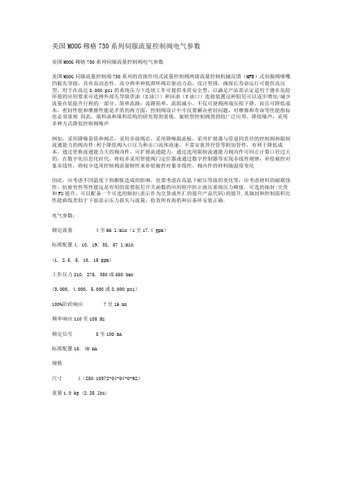
美国MOOG穆格730系列伺服流量控制阀电气参数美国MOOG穆格730系列伺服流量控制阀电气参数美国MOOG伺服流量控制阀730系列的直接作用式流量控制阀两级流量控制机械反馈(MFB)式伺服阀喷嘴挡板先导级,具有高动态性、高分辨率和低滞环阀芯驱动力高,设计坚固,确保长寿命运行可提供高压型,用于在高达8,000 psi的系统压力下连续工作可提供本质安全型,以满足产品需认证适用于潜在危险环境的应用要求可选择外部先导级供油(X油口)和回油(Y油口)连接装置这种阻尼可以逐步增加/减少流量在低提升行程的一部分。
简单流路:流路简单,流阻减小,不仅可使阀两端压损下降,而且可降低成本,密封性能和摩擦性能是矛盾的两方面,控制阀设计中不仅要解决密封问题,对摩擦和寿命等性能指标也必须重视因此,填料函和填料结构的研究得到重视,旋转型控制阀得到较广泛应用,降低噪声,采用多种方式降低控制阀噪声例如,采用降噪套筒和阀芯,采用多级阀芯,采用降噪限流板,采用扩展器与管道同直径的控制阀和限制流通能力的阀内件:利于降低阀入口压力和出口流体流速,不需安装异径管等附加管件,有利于降低成本,通过更换流通能力大的阀内件,可扩展流通能力,通过选用限制流通能力阀内件可纠正计算口径过大的,在数字化信息化时代,将较多采用智能阀门定位器或通过数字控制器等实现非线性规律,补偿被控对象非线性,将较少选用控制阀流量特性来补偿被控对象非线性,阀内件的材料随温度变化因此,应考虑不同温度下热膨胀造成的影响,也要考虑在高温下耐压等级的变化等,应考虑材料的耐腐蚀性、抗疲劳性等性能这是有用的需要阻尼开关函数的应用程序防止液压系统压力峰值。
可选的轴封:交货和FX提升,可以配备一个可选的轴封(表示作为交货或外汇的提升产品代码)的提升,其轴封和控制面积比性能曲线类似于下面显示压力损失与流量,检查所有海豹和后备环安装正确。
电气参数:额定流量 4至66 l/min(1至17.4 gpm)标准配置4, 10, 19, 38, 57 l/min(1, 2.5, 5, 10, 15 gpm)工作压力210, 275, 350或550 bar(3,000, 4,000, 5,000或8,000 psi)100%阶跃响应7至16 ms频率响应110至185 Hz额定信号 8至100 mA标准配置15, 40 mA规格尺寸 4(ISO 10372-04-04-0-92)重量1.0 kg (2.25 lbs)。
DDV说明书
MOOGMOOG( 穆格 )DDV 伺服阀MOOG( 穆格 )D633 、 D634 系列伺服阀是 MOOG 公司最新研制成功的新型电液伺服阀,目前已由 MOOG GmbH( 德国 ) 公司进行批量生产。
它是一种直接驱动式伺服阀,简称DDV(Direct Drive Servo Valve 的缩写 ),油口与安装尺寸D633 按 NG6(Cetop 3),D634 按NG10(Cetop 5) ,用集成电路实现阀芯位置的闭环控制,阀芯的驱动装置是永磁直线力马达。
对中弹簧使阀芯保持在中位,直线力马达克服弹簧的对中力使阀芯在两个方向都可偏离中位,平衡在一个新的位置,这样就解决了比例电磁线圈只能在一个方向产生力的不足之处。
阀芯位置闭环控制电子线路与脉宽调制(PWM )驱动电子线路固化为一块集成块,用特殊的连接技术固定在伺服阀内,因此 D633、D634 系列伺服阀无需配套电子装置就能对其进行控制。
D633、 D634 系列伺服阀是MOOG 公司对其经久考验,盛名于世的双喷嘴力反馈两级伺服阀的发展与补充,和传统的MOOG30 、31、 32、 34、 35、E760 等系列伺服阀相比,其最大的区别在于D633、D634 系列伺服阀从结构上取消了喷嘴一挡板前置级、用大功率的直线力马达替代了小功率的力矩马达,用先进的集成块与微型位置传感器替代了工艺复杂的机械反馈装置—力反馈杆与弹簧管,从而简化了结构,提高了可靠性,大大地降低了制造成本,却保持了带喷挡前置级的两级伺服阀的基本性能与技术指标。
MOOG DDV 伺服阀的特点1.在位置、速度、压力以及力电液伺服系统中可用二位二通、三位三通或三位四通的方式进行工作。
2.安装形式与尺寸符合DIN24340 和 cetop3 与 6。
3.无液压前置级。
4.停电、电缆损坏、或者紧急停车情况下伺服阀均能自行回中,无需外力推动。
5.动态性能指标与供油压无关。
6.防水性为IP65(DIN40050) 级。
Moog Inc. Series 72K 电液伺服阀手册说明书
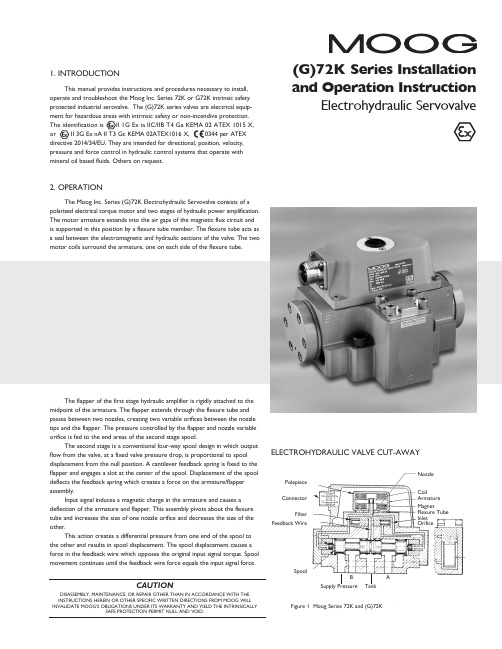
�(G)72K Series Installation ELECTROHYDRAULIC VALVE CUT-AWAYCoilArmature MagnetFlexure Tube Inlet OrificePolepiece ConnectorFilterFeedback WireSpoolFigure 1 Moog Series 72K and (G)72KSupply PressureBTankANozzle3. ELECTRICAL INFORMATION AND INTRINSICALLY SAFE CIRCUIT SAFETY PARAMETERSa. A wide choice of coils is available for a variety of rated currentrequirements. The torque motor coil leads are attached to the connector so external connections can provide series, parallel or single coiloperation. The valves are equipped either with an MS type connector or with pigtail leads for electrical wiring. Refer to installation drawings of the specific model for details. Servovalve coils should be driven with current to provide consistency throughout the temperature range.b. The (G)72K valves are approved for intrinsically safe protection per EN60079-11. The approved safety parameters are listed in the following table for all the coils used by (G)72K series. Coil number is marked on thevalve nameplate.Coil Configuration Marking U i (MAX) I i (MAX) G4220-031 (single, series, parallel) Ex ia IIB T4 12 V 120 mAG4220-051/098 (single, series, parallel) Ex ia IIB T4 12 V 240 mAG4221-001 G4220-042 (single) Ex ia IIC T4 16 V 160 mA G4221-001 G4220-042 (single) Ex ia IIC T4 24.4 V 85 mAG4220-031 (single, parallel) Ex ia IIC T4 30 V 26 mAG4220-031 (series) Ex ia IIC T4 30 V 18 mAG4220-051/098 (single, parallel) Ex ia IIC T4 30 V 19 mA G4220-051/098 (series) Ex ia IIC T4 30 V 12.7 mAG4220-042 (single) Ex ia IIC T4 30 V 37 mAG4220-042 (parallel) Ex ia IIC T4 30 V 20 mAG4220-042 (series) Ex ia IIC T4 30 V 10 mAG4221-001 (single) Ex ia IIC T4 30 V 28 mAc. The (G)72K valves are approved for non-incendive operation for supplycurrent not to exceed 50 mA dc.d. When making electric connections to the valve, appropriate measures mustbe taken to ensure that locally different earth potential do not result inexcessive ground currents. When barriers are required for the hazardous location, hazardous area (field) wiring must meet the requirements ofthe barrier manufacturer. All barriers must be mounted and installed incompliance with the barrier manufacturer’s requirements. Twisted pairs of 18-20 gage wire are recommended. If shielded wire is used, connect shield wire to earth ground only at the barrier strip.4. SPECIAL CONDITIONS FOR SAFE USEBecause the enclosure of the apparatus is made of aluminum, if it is mounted in an area where the use of category 1 G apparatus is required, it must be installed such that even in the event of rare incidents, ignition sources due to impact and friction sparks are excluded.When the electrohydraulic servovalve is used in an application for type of explosion protection intrinsic safety “i”, the appropriate box on the data label must be scored. When the electrohydraulic servovalve is used in an application for type of explosion protection “n”, the appropriate box on the data label must be scored.After use in an application for type of explosion protection “n”, the servovalve cannot abe safely used in a intrinsically safe application.The screwed cable connector may only be disconnected when the circuit is de-energized or when the location is known to be non-hazardous.When used at an ambient temperature ≥70°C, heat resistant cable must be used with a continuous operating temperature in accordance with the application.5. HYDRAULIC SYSTEM PREPARATIONTo prolong servovalve operational life and to reduce hydraulic system maintenance, it is recommended that the hydraulic fluid be kept at a cleanliness level of ISO DIS 4406 Code 16/13 maximum, 14/11 recommended. The most effective filtration scheme incorporates the use of a kidney loop or “off-line” filtration as one of the major filtration components. The filter for the “off-line” filtration scheme should be a ß3≥75 filter for maximum effectiveness.Upon system startup and prior to mounting the servovalve, the entire hydraulic system should be purged of built-in contaminating particles by an adequate flushing. The servovalve should be replaced by a flushing manifold and the hydraulic circuit powered up under conditions of fluid temperature and fluid velocity reasonably simulating normal operating conditions. New system filters are installed during the flushing process whenever the pressure drop across the filter element becomes excessive. The flushing processes should turn over the fluid in the reservoir between fifty to one hundred times.To maintain a clean hydraulic system, the filters must be replaced ona periodic basis. It is best to monitor the pressure drop across the filter assembly and replace the filter element when the pressure drop becomes excessive. In addition to other filters that are installed in the hydraulic circuit, it is recommended that a large capacity, low pressure ß3≥75 filter be installedin the return line. This filter will increase the interval between filter element replacements and greatly reduce the system contamination level.6. INSTALLATIONThe Moog (G)72K series industrial servovalve may be mounted in any position, provided the servovalve pressure, control, and tank ports match respective manifold ports. The mounting pattern and port location of the servovalve is shown on Figure 4. The servovalve should be mounted with 3/8-16 x 2.00 inch long, socket head cap screws. Apply a light film of oil to the screw threads and torque to 175 inch-pounds. Wire mating connector for desired coil configuration and polarity. Thread connector to valve.7. MECHANICAL NULL ADJUSTMENTIt is often desirable to adjust the flow null of a servovalve independent of other system parameters. The “mechanical null adjustment” on the Moog (G)72K Series servovalve allows at least ±20% adjustment of flow null. The “mechanical null adjustor” is an eccentric bushing retainer pin, located above the tank port designation on the valve body (see Figure 2) which, when rotated, provides control of the bushing position. Mechanical feedback elements position the spool relative to the valve body for a given input signal. Therefore, a movement of the bushing relative to the body changes the flow null. Mechanical Adjustment ProcedureUsing a 3/8 inch offset box wrench, loosen the self-locking fitting until thenull adjustor pin can be rotated. (This should usually be less than 1/2 turn). DO NOT remove self-locking fitting. Insert a 3/32 inch Allen wrench in null adjustor pin. Use the 3/32 Allen wrench to rotate the mechanical null adjustor pin to obtain desired flow null. Torque self-locking fitting to 57 inch lbs. Note:Clockwise rotation of null adjustor pin produces flow from port P to port B.Tools and Equipmenta. Blade screwdriverb. Allen wrench set (3/32, 7/64, 3/8, 3/16)c. No. 2-56 NC by 11/2 inch screwd. Torque wrenchese.3/8 inch offset box wrenchf. TweezersFigure 2Mechanical NullAdjustment10. FIELD REPLACEABLE FILTER ASSEMBLY REPLACEMENTa.Remove four socket head cap screws and lockwashers on filter cover using a 3/16 inch Allen wrench. Remove filter cover plate. Use to pull filter plug out.b. Remove o-rings and old filter from filter plug.c. Inspect filter for foreign material and discard.d. Install o-rings on filter plug and inside new filter.e.Install filter, filter plug and cover plate. Torque screws to 85 inch-pounds.11. FUNCTIONAL CHECKOUT AND CENTERINGa. Install servovalve on hydraulic system or test fixture, but do not connect electrical lead.b. Apply required system pressure to servovalve and visually examine for evidence of external leakage. If leakage is present and cannot be rectified by replacing o-rings, remove the discrepant component and return for repair or replacement.Note: If the system components are drifting or hardover, adjust the mechanical null of the servovalve.c. Connect electrical lead to servovalve and check phasing in accordancewith system requirements.Figure 3Filter Tube Inlet Orifice AssemblyFilter PlugFieldReplaceable FilterFilter HousingO-Rings8. GENERAL SERVICING RECOMMENDATIONSa. Disconnect electrical lead to servovalve.b. Relieve hydraulic system of residual pressure.(G)72K SERIES INSTALLATION AND OPERATION INSTRUCTIONCDS6754 RevD 500-448 0718Moog Inc., East Aurora, NY 14052-0018 Telephone: 716/652-2000Fax: 716/687-7910Toll Free: 1-800-272-MOOG TYPICAL WIRING SCHEMATICThe products described herein are subject to change at any time without notice, including, but not limited to, product features, specifications, and designs.3。
MOOG伺服阀D660系列阀卡D122-034-013C调试指导手册
MOOG伺服阀D660系列速度/ 压力控制卡(DC)调试指导手册:编制:海天科技部日期:以下为DC阀卡实样图[】%}。
一.对DC阀卡功能的一些说明:1.在对阀卡的调试过程中,和调试人员相关只有三个部分,包括调试区(R1-R16共16个电阻)、跳线区(J1-J23共23个跳线)、监控区(TP1-TP17共17个监控脚和5个逻辑指示灯)2.调试人员调试工作要解决的问题包括以下几个方面:■开环射退速度控制调节<■保压压力控制调节■注射速度控制调节■注射压力控制调节■背压压力控制调节3.可调电阻功能说明(R1-R16)■R1: 最大注射实际速度调节■R2: 压力传感器零点(最小值)校正*■R3: 压力传感器量程(最大值)校正■R4: 10%压力平衡线性校正(需反复调整至最优)■R5: 90%压力平衡线性校正(需反复调整至最优)■R6: 注射速度比例(P)増益调节■R7: 注射速度积分(I)増益调节■R8: 保压压力比例(P)増益调节■R9: 保压压力积分(I)増益调节■R10:背压压力比例(P)増益调节}■R11:背压压力积分(I)増益调节■R12:背压信号偏置调节■R13:射退速度信号偏置调节■R14: 调节保压压力控制积分(I)增益延时时间(15-100 ms) 调节■R15: 注射压力限制(P)增益调节■R16: 注射压力限制(I)增益调节4.监测点功能说明(TP1-TP17)·■TP1: 设定速度模拟量监控(0 - +10V)■TP2: 实际反馈速度模拟量监控(0 - +10V)■TP3: 设定压力模拟量监控(0 - +10V)■TP4: 实际反馈压力模拟量监控(0 - +10V)■TP5: 位置传感器正向输出监控(0 - +10V)■TP6: 位置传感器反向输出监控(0 - -10V)■TP7: 监测可调电阻R2: (压力传感器零点调整点)■TP8: 监测R4调整压力10% 平衡输出—■TP9: 监测背压压力信号偏移电压(-15V - +15V)■TP10: 监测R13射退速度信号偏移调节点■TP11: 监测伺服卡给伺服阀的电压信号(-10V - +10V)■TP13: 模拟量信号地■TP14: MOOG压力传感器(5V)电源监测点■TP16: 伺服卡向外输出的–15V电压点■TP17: 伺服卡向外输出的+15V电压点5.跳线设置点功能说明■J1: 没有用处:■J2: 没有用处■J3: 保压压力控制积分“I” 增益时间常数: X3■J4: 保压压力控制积分“I” 增益时间常数: X2■J5: 保压压力控制积分“I” 增益时间常数: X1■J6: 保压压力积分“I “ 增益选择(插上红盖后表示不要积分“I “ 增益)■J7 + J8: 注射压力限制选择开(注射压力限制起作用)■J9 + J10: 注射压力限制选择关(注射压力限制不起作用)■J11: 注射速度输出增益选择(范围: 1 – 20)《■J12: 注射速度输出增益选择(范围: 1 – 40)■J13 + J23: 注射动作行程采用线性电子尺■J14 + J22: 注射动作行程采用脉冲发生器(像编码器等)■J15: 速度输出偏置补偿■J16 + J17: 适用于MOOG压力传感器(350 bar)■J18 + J19: 适用于MOOG压力传感器(210 bar)■J20 + J21: 适用于满量程为+5 or +10v压力传感器;6.动作逻辑指示灯功能说明动作逻辑指示灯总共有5个,以R1-R16自上至下方向依次为D1-D5■第一个D1灯亮表示注射动作逻辑通了■第二个D2灯亮表示保压动作逻辑通了■第三个D3灯亮表示背压动作逻辑通了■第四个D4灯亮表示射退动作逻辑通了■第五个D5灯亮表示伺服阀处于过载状态(调试人员可以忽略不见)/二.调试前需要准备的工作和仪器■注塑机在装上普通方向阀试车时应该校正完相关参数,机器动作正常■装上MOOG伺服阀■吊上标准块■装上料斗并准备好PP料■准备示波仪、外用表、调试专用连接夹头、电源插座、手电筒、螺丝刀等■注塑机的相关参数:注射油缸最高设计压力(bar)、注射最快设计速度(mm/s)、注射最大设计行程、压力传感器最高压力等级【三.调试开始及步骤每次更换和安装V/P 卡后,必须按以下12个步骤依次进行第一步:设置跳线,第二步:具体调试前检查第三步:注射、射退动作试运行第四步:伺服阀零位调整第五步:射退速度调整第六步:压力传感器校正(零位& 量程)第七步:保压压力调试第八步:保压压力调整优化第九步:注射速度校正和优化—第十步:注射压力限制优化第十一步:背压压力优化第十二步:零背压压力优化第一步:设置跳线1.对所有海天的注塑机而言,调试前跳线跳完后只有以下两种:①J1、J2、J4、J6、J9、J10、J11、J13、J20、J21、J23②J1、J2、J4、J6、J9、J10、J12、J13、J20、J21、J23.那么调试人员如何来区分以上两种跳线呢方法很简单:调试人员可以根据以下公式来估算:注射最大设计行程٪注射最快设计速度= 注射时间如果注射时间小于秒,那么选择第①种跳线如果注射时间大于秒,那么选择第②种跳线以上是调试前的跳线状态,那么在调试全部完毕后,其对应的跳线状态如下:(调试人员调完后应检查是否是以下状态,如果不对,那么调试肯定有问题)①J1、J2、J4、J7、J8、J11、J13、J20、J21、J23;②J1、J2、J4、J7、J8、J12、J13、J20、J21、J23第二步:具体调试前检查调试前,请检查以下信号:■V/P卡24vdc电源,端子20 为24v, 端子24为0v取下伺服阀插头,伺服阀插头孔A 为24v,孔B为0v■关掉马达,分别给4个逻辑信号(注射、保压、预塑、射退)强制输出,检查对应的逻辑灯D1、D2、D3 、D4分别发光,确认信号接线正确■关掉马达,检查V/P卡上速度和压力模拟量指令信号:强制输出最大速度,其对应模拟量电压应为+10V;强制输出最大压力,其对应模拟量电压应为+10V,多次改变控制器的输出指令来检查其对应的模拟量电压值,主要是确认控制器指令输出线性是否良好,同时确认V/P卡是否接收信号良好。
G771 G772 G773电动液压工业伺服阀安装、操作和故障排除手册

G77X/77X Series Installationand Operation Instruction ELECTROHYDRAULIC VALVE CUT -AWA YUpper Polepiece Flexure Sleeve Lower Polepiece Flapper Magnet (not shown)Coil Figure 1 Moog Series G77X/77X3.HYDRAULIC SYSTEM PREPARATIONT o prolong servovalve operational life and to reduce hydraulic system maintenance,it is recommended that the hydraulic fluid be kept at a cleanliness level of ISO DIS 4406 Code 16/13 maximum,14/11 recommended.The most effective filtration scheme incorporates the use of a kidney loop or “off-line”filtration as one of the major filtration components.The filter for the “off-line”filtration scheme should be a ß3≥75 filter for maximum effectiveness. Upon system startup and prior to mounting the servovalve,the entire hydraulic system should be purged of built-in contaminating particles by an adequate flushing.The servovalve should be replaced by a flushing manifold and the hydraulic circuit powered up under conditions of fluid temperature and fluid velocity,reasonably simulating normal operating conditions.New system filters are installed during the flushing process whenever the pressure drop across the filter element becomes excessive.The flushing processes should turn over the fluid in the reservoir between fifty to one hundred times.T o maintain a clean hydraulic system,the filters must be replaced on a periodic basis.It is best to monitor the pressure drop across the filter assembly and replace the filter element when the pressure drop becomes excessive.In addition to other filters that are installed in the hydraulic circuit,it is recommended that a large capacity,low pressure ß3≥75 filter be installed in the return line.This filter will increase the interval between filter element replacements and greatly reduce the system contamination level.4.INSTALLATIONThe Moog G77X/77X Series Industrial Servovalve may be mounted in any position,provided the servovalve pressure,piston and return ports match respective manifold ports.The mounting pattern,port location and mounting bolts of the servovalve are shown on Figure 4.Apply a light film of oil to the screw threads and torque to 57 inch-pounds.Wire mating connector for desired coil configuration and polarity. Thread connector to valve.5.MECHANICAL NULL ADJUSTMENTIt is often desirable to adjust the flow null of a servovalve independent of other system parameters.The “mechanical null adjustment” on the MoogG77X/77X Series servovalve allows at least ±20% adjustment of flow null.The “mechanical null adjustor” is an eccentric bushing retainer pin located above the port designation on the valve body (see Figure 2) which,when rotated,provides control of the bushing position.Mechanical feedback elements position the spool relative to the valve body for a given input signal.Therefore,a movement of the bushing relative to the body changes the flow null.Adjustment ProcedureUsing a 3/8inch offset box wrench,loosen the self-locking fitting until the null adjustor pin can be rotated.(This should usually be less than 1/2 turn). DO NOT remove self-locking fitting.Insert a 3/32inch Allen wrench in null adjustor e the 3/32Allen wrench to rotate the mechanical null adjustor pin to obtain desired flow null.T orque self-locking fitting to 57 inch lbs.Note:Clockwise rotation of null adjustor pin produces open loop flow from port B to port A.6.GENERAL SERVICING RECOMMENDATIONSa.Disconnect electrical lead to servovalve.b.Relieve hydraulic system of residual pressure.c.Remove servovalve.Figure 2Mechanical Null AdjustmentFILTER ASSEMBL Y REPLACEMENTRemove four socket head cap screws and lockwashers using a 3/16inch End capEnd Cap O-RingsFigure 3FilterInlet Orifice O-Rings (two at each end cap)G77X/77X SERIES INSTALLATION AND OPERATION INSTRUCTIONMoog Inc.,East Aurora,NY 14052-0018 T elephone:+1-716-652-2000Fax:+1-716-687-7910T oll Free:+1-800-272-MOOG /industrial©2007 Moog Inc.All changes are reserved.NOTESTYPICAL WIRING SCHEMATIC3Figure 447.81.5744.5MAX47.81.34335.364.7726.2P3.0OR[28.4] 1.751.275.8441.06MAX PIN C 1.00 2.122.182.8117.04.0141.68834.111.561.88PIN D1.88.12.007(OPTION)21.4425.426.91.3939.61.12 MAX 1.03MTG HGTPIN B.67153.855.471.4PIN A32.392.55042.88ELECTRICAL CONNECTORLOCATING PINØ.062EXTERNAL NULL ADJUST 3/32 IN. HEX SOCKET4X Ø.221(5.61) THRU (G771 AND G772)4X Ø.265(6.73) THRU (G773)YX TBA PF2F3F4F1T GThe products described herein are subject to change at any time without notice, including, but not limited to, product features, specifications, and designs.4 6CDS6674 REV C 500-380 807。
伺服阀使用说明书
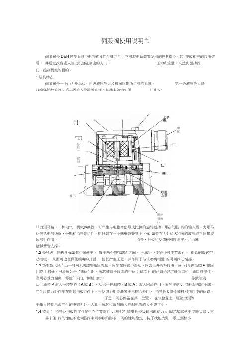
伺服阀使用说明书伺服阀是DEH 控制系统中电液转换的关键元件,它可将电调装置发出的控制指令,转 变成相应的液压信号, 并通过改变进入油动机油缸液流的方向、压力和流量,来达到驱动阀门、控制机组的目的。
1结构特点伺服阀是一个由力矩马达、两级液压放大及机械反馈所组成的系统。
第一级液压放大是 双喷嘴挡板系统;第二级放大是滑阀系统。
其基本结构如图 1所示。
i.i 力矩马达:一种电气一机械转换器,可产生与电指令信号成比例的旋转运动,用在伺服 阀的输入级。
力矩马达包括电气线圈、极靴和衔铁等组件。
衔铁装在一个薄壁弹簧管上,弹 簧管在力矩马达和阀的液压段之间起流体密封作用。
衔铁、挡板和反馈杆刚性固接,并由薄壁弹簧管支撑。
1.2先导级:挡板从弹簧管中间伸出, 置于两个喷嘴端面之间, 形成左、右两个可变节流孔。
衔铁的偏转带动挡板, 从而可改变两侧喷嘴的开启, 使其产生压差,并作用于与该喷嘴相通 的滑阀阀芯端部。
1.3功率放大级:由一滑阀系统控制输出流量。
阀芯在阀套中滑动,阀套上开有环行槽,分 别与供油腔P 和回油腔T 相通。
当滑阀处于“零位”时,阀芯被置于阀套的中位;阀芯上 的凸肩恰好将进油口和回油口遮盖住。
当阀芯受力偏离“零位”向任一侧运动时, 导致油液 从供油腔P 流入一控制腔(A 或B ),从另一控制腔(B 或A )流入回油腔 T 。
阀芯推动反 馈杆端部的小球,产生反馈力矩作用在衔铁挡板组件上。
当反馈力矩逐渐等于电磁力矩时, 衔铁挡板组件被移回到对中的位置。
于是,阀芯停留在某一位置。
在该位置上,反馈力矩等 于输入控制电流产生的电磁力矩,因此,阀芯位置与输入控制电流的大小成正比。
1.4 特点: 衔铁及挡板均工作在中立位置附近 , 线性好 喷嘴挡板级输出驱动力大 阀芯基本处于浮动状态 , 不易卡住 阀的性能不受伺服阀中间参数的影响 , 阀的性能稳定 , 抗干扰能力强 , 零点漂移小 圃定节流口 F芯阀F駅肝—— 控轴畫的出逵电插2 工作原理:当力矩马达没有电信号输入时,衔铁位于极靴气隙中间,平衡永久磁铁的磁性力。
穆格(Moog) G761 -761系列流量控制伺服阀说明书
为高性能两级设计的流量控制阀,结构简单、坚固,工作可靠,使用寿命长。
2021 年 9 月哪里需要最高水平的运动控制性能和设计灵活性,哪里就能看到穆格技术。
通过协作、创新以及世界级水平的技术解决方案,我们将助您攻克最艰巨的工程难关。
穆格旨在帮助您提高机器的性能,获取超乎想象的新体验。
简介 (2)产品概述 (3)工作原理 (5)技术参数 (6)G761/-761 系列伺服阀 (6)安装图 (11)安装要求 (12)电气接线 (13)背景 (14)流量计算 (14)订货信息 (15)备件及附件 (15)相关产品 (16)关于穆格 (17)订货编码 (19)本产品样本用于为具有一定专业知识的客户提供信息和参数。
为确保获得系统功能和系统的安全性,请对照此样本仔细查看产品的适用性。
文中所述产品如有任何更改,恕不另行通知。
如果有任何疑问,请与穆格公司联系。
Moog 是穆格公司及其子公司的注册商标。
除非另有说明,文中出现的所有商标均为穆格及其子公司所有。
产品概述阀的设计 带阀芯、阀套和干式力矩马达的两级伺服阀安装型式ISO 10372-04-04-0-92P、A、B 和 X 口最大工作压力• 铝制阀体:315 bar (4,500 psi)• 钢制阀体:350 bar (5,000 psi)T 口最大工作压力210 bar (3,000 psi)先导阀喷嘴挡板阀为 35 bar/每一节流边 (500 psi /每一节流边)时的额定流量Δp N 0.5 至 75 l/min (0.125 至 19.5 gpm)从 0 至 100% 行程的阶跃响应时间标准响应型: < 8 ms 高响应型: < 6 ms 超高响应型: < 4 ms在有潜在危险的环境中可以选用本质安全型和防爆型伺服阀。
特殊型号均经过 FM、ATEX、CSA、TIIS 和 IECEx标准认证。
详细信息请联系穆格获取。
文件文件名称说明备注穆格文件号目录G761/-761 系列基本信息注:请访问 /industrialCDL6642手册G761/-761CDS6673G761K/-761K 本质安全型系列CDS6769安装图G761/-761 1系列总体设计CB59420G761K/-761K 系列,2 组线圈CA33637G761/-761 系列流量控制伺服阀是可用作三通和四通节流型流量控制阀,用于四通阀时控制性能更好。
穆格D661系列伺服阀说明书

UD-E=0-+10V Re:10KΩ
!"#$%
&"#'
! ! ! UD-B
ID=-IE: 0-±10mA (Re=200)
! IE=-ID: 0-±10mA
UE-B
!" -15V~+32V
IF-B=4-20mA 12mA
!"#$%&RL=100-500Ω
!D
23
UF-B=2-10V, 6V
!"#$%Ra=500
!"# !"#$%"#
!
PN=0.5MPa/
!"
!
! P A B (X
)
T (Y
)
T (Y
)
!
!"#
!"#$%
! * 0-100%
!"#$%&'
!"#$
!"#$%&'( 6
!"#$%&'
!"
24VDC,
18VDC,
32VDC
!"#$ 300mA
!"#$
!"#$%&'(
!"#$%&
!"#$%&$'()% 0V
!"# EMC
!
EMC
EN 55011:1998 B
! EN50082-2:1995A
!
!"#$%&'()*+,-./0 !"#$%&0.75mm2.
!"#$%&'()*
伺服阀使用说明书
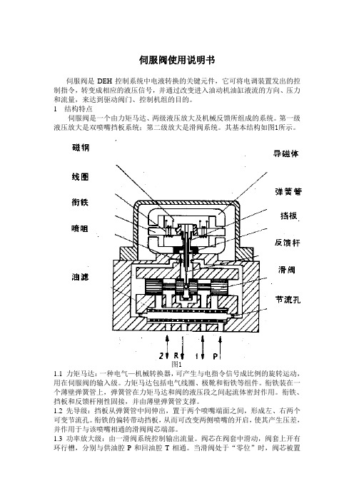
伺服阀使用说明书伺服阀是DEH控制系统中电液转换的关键元件,它可将电调装置发出的控制指令,转变成相应的液压信号,并通过改变进入油动机油缸液流的方向、压力和流量,来达到驱动阀门、控制机组的目的。
1 结构特点伺服阀是一个由力矩马达、两级液压放大及机械反馈所组成的系统。
第一级液压放大是双喷嘴挡板系统;第二级放大是滑阀系统。
其基本结构如图1所示。
图11.1 力矩马达:一种电气—机械转换器,可产生与电指令信号成比例的旋转运动,用在伺服阀的输入级。
力矩马达包括电气线圈、极靴和衔铁等组件。
衔铁装在一个薄壁弹簧管上,弹簧管在力矩马达和阀的液压段之间起流体密封作用。
衔铁、挡板和反馈杆刚性固接,并由薄壁弹簧管支撑。
1.2 先导级:挡板从弹簧管中间伸出,置于两个喷嘴端面之间,形成左、右两个可变节流孔。
衔铁的偏转带动挡板,从而可改变两侧喷嘴的开启,使其产生压差,并作用于与该喷嘴相通的滑阀阀芯端部。
1.3 功率放大级:由一滑阀系统控制输出流量。
阀芯在阀套中滑动,阀套上开有环行槽,分别与供油腔P和回油腔T相通。
当滑阀处于“零位”时,阀芯被置于阀套的中位;阀芯上的凸肩恰好将进油口和回油口遮盖住。
当阀芯受力偏离“零位”向任一侧运动时,导致油液从供油腔P流入一控制腔(A或B),从另一控制腔(B或A)流入回油腔T。
阀芯推动反馈杆端部的小球,产生反馈力矩作用在衔铁挡板组件上。
当反馈力矩逐渐等于电磁力矩时,衔铁挡板组件被移回到对中的位置。
于是,阀芯停留在某一位置。
在该位置上,反馈力矩等于输入控制电流产生的电磁力矩,因此,阀芯位置与输入控制电流的大小成正比。
1.4 特点:●衔铁及挡板均工作在中立位置附近,线性好●喷嘴挡板级输出驱动力大●阀芯基本处于浮动状态,不易卡住●阀的性能不受伺服阀中间参数的影响,阀的性能稳定,抗干扰能力强,零点漂移小2 工作原理:当力矩马达没有电信号输入时,衔铁位于极靴气隙中间,平衡永久磁铁的磁性力。
当有欲使调节阀动作的电气信号由伺服放大器输入时,力矩马达的线圈中有电流通过,产生一磁场,在磁场作用下,产生偏转力矩,使衔铁旋转,同时带动与之相连的挡板转动,此挡板伸到两个喷嘴中间。
伺服阀使用说明书
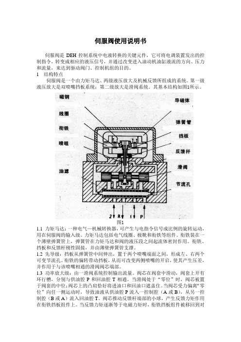
伺服阀使用说明书伺服阀是DEH控制系统中电液转换的关键元件,它可将电调装置发出的控制指令,转变成相应的液压信号,并通过改变进入油动机油缸液流的方向、压力和流量,来达到驱动阀门、控制机组的目的。
1 结构特点伺服阀是一个由力矩马达、两级液压放大及机械反馈所组成的系统。
第一级液压放大是双喷嘴挡板系统;第二级放大是滑阀系统。
其基本结构如图1所示。
图11.1 力矩马达:一种电气—机械转换器,可产生与电指令信号成比例的旋转运动,用在伺服阀的输入级。
力矩马达包括电气线圈、极靴和衔铁等组件。
衔铁装在一个薄壁弹簧管上,弹簧管在力矩马达和阀的液压段之间起流体密封作用。
衔铁、挡板和反馈杆刚性固接,并由薄壁弹簧管支撑。
1.2 先导级:挡板从弹簧管中间伸出,置于两个喷嘴端面之间,形成左、右两个可变节流孔。
衔铁的偏转带动挡板,从而可改变两侧喷嘴的开启,使其产生压差,并作用于与该喷嘴相通的滑阀阀芯端部。
1.3 功率放大级:由一滑阀系统控制输出流量。
阀芯在阀套中滑动,阀套上开有环行槽,分别与供油腔P和回油腔T相通。
当滑阀处于“零位”时,阀芯被置于阀套的中位;阀芯上的凸肩恰好将进油口和回油口遮盖住。
当阀芯受力偏离“零位”向任一侧运动时,导致油液从供油腔P流入一控制腔(A或B),从另一控制腔(B或A)流入回油腔T。
阀芯推动反馈杆端部的小球,产生反馈力矩作用在衔铁挡板组件上。
当反馈力矩逐渐等于电磁力矩时,衔铁挡板组件被移回到对中的位置。
于是,阀芯停留在某一位置。
在该位置上,反馈力矩等于输入控制电流产生的电磁力矩,因此,阀芯位置与输入控制电流的大小成正比。
1.4 特点:●衔铁及挡板均工作在中立位置附近,线性好●喷嘴挡板级输出驱动力大●阀芯基本处于浮动状态,不易卡住●阀的性能不受伺服阀中间参数的影响,阀的性能稳定,抗干扰能力强,零点漂移小2 工作原理:当力矩马达没有电信号输入时,衔铁位于极靴气隙中间,平衡永久磁铁的磁性力。
当有欲使调节阀动作的电气信号由伺服放大器输入时,力矩马达的线圈中有电流通过,产生一磁场,在磁场作用下,产生偏转力矩,使衔铁旋转,同时带动与之相连的挡板转动,此挡板伸到两个喷嘴中间。
Moog G761 761系列工业伺服阀安装、操作和故障排除手册说明书

ELECTROHYDRAULIC VALVE CUT -AWA YFigure 1 Moog Series G761/761Upper Polepiece Flexure Tube Lower Polepiece FlapperInlet OrificeCoil Armature NozzleFeedback WireSpoolP A T B P xFilter3. HYDRAULIC SYSTEM PREPARATIONT o prolong servovalve operational life and to reduce hydraulic system maintenance, it is recommended that the hydraulic fluid be kept at a cleanliness level of ISO DIS 4406 Code 16/13 maximum, 14/11 recommended. The most effective filtration scheme incorporates the use of a kidney loop or “off-line” filtration as one of the major filtration components. The filter for the “off-line” filtration scheme should be a B 3≥75 filter for maximum effectiveness.U pon system startup and prior to mounting the servovalve, the entire hydraulic system should be purged of built-in contaminating particles by an adequate flushing. The servovalve should be replaced by a flushing manifold and the hydraulic circuit powered up under conditions of fluid temperature and fluid velocity, reasonably simulating normal operating conditions. New system filters are installed during the flushing process whenever the pressure drop across the filter element becomes excessive. The flushing processes should turn over the fluid in the reservoir between fifty to one hundred times.T o maintain a clean hydraulic system, the filters must be replaced on a periodic basis. It is best to monitor the pressure drop across the filter assembly and replace the filter element when the pressure drop becomes excessive. In addition to other filters that are installed in the hydraulic circuit, it is recommended that a large capacity, low pressure ß3≥75 filter be installed in the return line. This filter will increase the interval between filter element replacement and greatly reduce the system contamination level.4. PILOT STAGE OIL SUPPL Y AND NAMEPLATEMODIFICATION (applies to models G761-3001B through G761-3010B)T he Moog G761/761 series industrial servovalve can be configured for pilot stage oil supply through the internal pressure “P” port, or from a separate supply line through the “X” port. Standard configuration is internal pilot operation with a screw and seal washer in the “X” port. This same screw and seal washer must be relocated to the “P” port if an external pilot oil supply source is desired. Refer to Figure 2 for screw and seal washer locations.U pon valve installation, the nameplate must display the proper hydraulic schematic and typecode (if applicable). The nameplate currently shows internal (4th port) pilot hydraulic schematics and typecode. If a separate pilot supply will be used, please attach the provided lower half label showing external (5th port) information. See Figure 3.5. INSTALLATIONT he Moog G761/761 series industrial servovalve may be mounted in any position, provided the servovalve pressure, control and return ports match their respective manifold ports.T he mounting pattern and port locations of the servovalve are shown on Figure 6. The servovalve should be mounted with 5/16-18 x 1.75 inch long, socket head cap screws. Apply a light film of oil to the screw threads and torque to 96 inch pounds. Wire the mating connector for desired coil configuration and polarity. Thread the connector to valve.6. NULL ADJUSTMENTI t is often desirable to adjust the flow null of a servovalve independent of other system parameters. The “mechanical null adjustment” on the Moog G761/761 series servovalve allows at least ±20% adjustment of flow null.T he “mechanical null adjustor” is an eccentric bushing retainer pin located above the “return” port designation on the valve body (see Figure 4) which, when rotated, provides control of the bushing position. Mechanical feedback elements position the spool relative to the valve body for a given input signal. Therefore, a movement of the bushing relative to the body, changes the flow null.Mechanical Adjustment ProcedureUsing a 3/8 inch offset box wrench, loosen the self-locking fitting until the null adjustor pin can be rotated. (This should usually be less than 1/2 turn). DO NOT remove self-locking fitting. Insert a 3/32 inch Allen wrench in null adjustor pin. Use the 3/32 Allen wrench to rotate the mechanical null adjustor pin to obtain desired flow null. T orque self-locking fitting to 57 inch lbs.Figure 3Sample Nameplate7. GENERAL SERVICING RECOMMENDATIONSa. Disconnect the electrical lead to the servovalve.b. Relieve the hydraulic system of residual pressure.c.Remove the servovalve.Figure 4Mechanical Null AdjustmentImportant:Local regulations may require precise hydraulic labeling on components!Potential TroubleServovalve does not follow input command signal. (Actuator or components are stationary or creeping slowly).High threshold. (Jerky, possible oscillatory or “hunting” motion in closed loop system).Poor response. (Servovalve output lags electrical command signal).High Null Bias, (High input currentrequired to maintain hydraulic cylinder or motor stationary).Probable Cause1. Plugged filter element.1. Plugged filter element.1. Partially plugged filter element.1. Incorrect null adjustment.2. Partially plugged filter element.Remedy1. Replace filter element.1. Replace filter element.1. Replace filter element.Check for dirty hydraulic fluid in system.1. Readjust null.2. Replace filter element and check for dirty hydraulic fluid in system.8. TROUBLESHOOTING CHARTThe following troubleshooting chart lists potential troubles encountered, probable causes and remedies.9. FILTER ASSEMBL Y REPLACEMENTT ools and Equipmenta. 3mm Allen wrenchb. T orque wrencha. Remove the four socket head cap screws with 3mm Allen wrench.b. Remove the filter retainer.c. Remove and discard the filter disc.d. Remove and replace the o-ring on the filter retainer and the o-ring in the filter bore.e.Reinstall in reverse order, torque screws to 35-40 in-lbs.10. FUNCTIONAL CHECK OUT AND CENTERINGa. Install servovalve on hydraulic system or test fixture, but do not connect electrical lead.b. Apply required system pressure to servovalve and visually examine for evi- dence of external leakage. If leakage is present and cannot be rectified by replacing o-rings, remove the discrepant component and return for repair or replacement.Note: If the system components are drifting or hardover, adjust the mechanical null of the servovalve.c. Connect electrical lead to servovalve and check phasing in accordancewith system requirements.11. AUTHORIZED REPAIR FACILITIESMoog does not authorize any facilities other than Moog or Moog subsidiaries to repair its servovalves. It is recommended you contact Moog at (716) 652-2000 to locate your nearest Moog repair facility. Repair by an independent (unauthorized) repair house will result in voiding the Moog warranty and could lead to performance degradation or safety problems.Figure 5Socket Head Cap Screw2X O-RingP/N -42082-003Filter RetainerFilterP/N A67999-0652X O-Ring P/N G2141-013-015G761/761 SERIES INSTALLATION AND OPERATION INSTRUCTION NOTES2Figure 6Moog Inc., Industrial Group/industrialUnitedStates:phone+****************************Europe:phone+*******************************AsiaPacific:phone+******************************For a complete list /industrial/globallocatorThe products described herein are subject to change at any time without notice, including, but not limited to, product features, specifications, and designs.CDS6673 Rev E 1216。
MOOG伺服阀说明书1
Servovalveswith integrated Electronics D791 and D792 SeriesQ [l/min]=max. flowD p [bar]=valve pressure dropwith Q A K [cm 2]=spool drive area p X [bar]=pilot pressure The pilot pressure p X has to be at least 15 bar above the returnpressure of the pilot stage.D791 and D792 SeriesThree stage servovalvesPrinciple of operationAn electrical command signal (set point, input signal) is applied to the integrated control amplifier which drives a current through the pilot valve coils. The pilot valve produces differential pressure in its control ports. This pressure difference results in a pilot flow which causes main spool dis-placement.The position transducer which is excited via an oscillator measures the position of the main spool (actual value, position voltage).This signal then is demodulated and fed back to the control amplifier where it is compared with the command signal. The control amplifier drives the pilot valve until the error between command signal and feedback signal is zero. Thus, the position of the main spool is proportional to the electrical command signal.Q Q p p NN=∆∆p 2,510QA pX -2K≥⋅⋅∆The actual flow depends on the electrical command signal and the valve pressure drop, and may be calculated using the square root function for a sharp-edged orifice.The flow value Q calculated in this way should not exceed an average flow velocity of 30 m/s in ports P, A, B and T.Q [l/min]=calculated flow Q N [l/min]=rated flowD p [bar]=actual valve pressuredropD p N [bar]=rated valve pressuredrop2If large flow rates with high valve pressure drops are required, an appropriate higher pilot pressure has to be chosen to overcome the flow forces. An approximate value can be calculated as follows:Our quality management system is certified in accordance with DIN EN ISO 9001.This catalogue is for users with technical knowledge. To ensure that all necessary characteristics for function and safety of the system are given, the user has tocheck the suitability of the products described here.In case of doubt please contact MOOG.The flow control servovalves D791and D792 Series are throttle valves for 3-way and preferably 4-way applications. These three stage servovalves have been especially developed for such demanding applications where high flow rates and at the same time extreme dynamic performance require-ments must be met. The design of these valves is based on the well known D079 Series. The inte-grated electronics has been replaced by a new design applying SMD technology. The valves areoffered with pilot valves of D761or D765 Series, optional standard response or high response versions are available. Series D791 can de-liver rated flow up to 250 l/min,Series D792 is available with rated flow up to 1000 l/min.These valves are suitable for pres-sure or force control, position and velocity control systems with high dynamic response requirements.D791 and D792 SeriesGeneral technical dataOperating pressure rangeMain stage Ports P, A and B with X internal up to 315 bar with X externalup to 350 bar Port T with Y internal up to 210 bar Port T with Y external up to 350 barPilot valve Ports P, A and B D761, D765 Series up to 315 bar Port Tup to 210 barTemperature rangeAmbient -20 to +60 °C Fluid-20 to +80 °CSeal material FPM, others on requestOperating fluid Mineral oil based hydraulic fluid (to DIN 51524), others on request Viscosityrecommended 15 to 100 mm²/s Class of cleanlinessThe cleanliness of the hydraulic fluid greatly effects the per-formance (spool positioning, high resolution) and wear (metering edges, pressure gain, leakage) ofthe valve.3T B P A3 stage ServovalveD791 / D792 Series with Pilot valve D765 SeriesRecommended cleanliness classfor normal operation:ISO 4406 < 14/11for longer life:ISO 4406 < 13/10System filtrationPilot valve:High pressure filter (without by-pass, but with dirt alarm) mountedin the mainflow and if possible,directly upstream of the servovalve.Main stage:Main stage: high pressure filter asfor the pilot stage. In combination with a fast regulating VD-pump a bypass filter is possible.Filter rating recommendedfor normal operation:ß10 ³ 75 (10 µm absolute)for longer life:ß5 ³ 75 ( 5 µm absolute)Installation options any position, fixed or movable Vibration 30 g, 3 axes Degree of protection EN 60529: IP 65 (with mating con-nector mounted)Shipping plate Delivered with an oil sealed ship-ping plate4Model . . . .TypeD791 . . . . S . . .Mounting patternISO, but X and Y do not corres-ISO 10372-06-05-0-92pond to ISOValve body version 4-way3-stage with bushing spool assembly Pilot valve2-stage, optional D761 or D765 SeriesPilot connection optional, internal or externalX and Y Mass[kg]13Rated flow (± 10%) at D p N = 35 bar per land [l/min]100160250Response time*for 0 to 100% stroke (depen-dent on pilot valve)[ms]3 to 10Threshold*[%]< 0,2Hysteresis*[%]< 0,5Null shiftwith D T = 55 K [%]< 2Null leakage flow*total, max.[l/min]5710Pilot leakage flow*max., for 100% step input (de-pendent on pilot valve)[l/min]4 to 11Main spool stroke [mm]1,61,62,0Main spool drive area[cm²]2,85* measured at 210 bar pilot or operating pressure, fluid viscosity of 32 mm²/s and fluid temperature of 40 °CValve flow diagramTypical characteristic curves measured at 210 bar pilot or operating pressure, fluid viscosity of 32 mm²/s and fluid temperature of 40 °CFrequency responsefor valves with different rated flows and different pilot valvesD791 SeriesTechnical dataModel . . . .TypeD792 . . . . S . . .Mounting pattern Moog StandardValve body version 4-way3-stage with bushing spool assembly Pilot valve2-stage, optional D761 or D765 SeriesPilot connection optional, internal or externalX and Y Mass[kg]17Rated flow (± 10%) at D p N = 35 bar per land [l/min]4006308001000Response time*for 0 to 100% stroke (depen-dent on pilot valve)[ms]4 to 12Threshold*[%]< 0,2Hysteresis*[%]< 0,5Null shiftwith D T = 55 K [%]< 2Null leakage flow*total, max.[l/min]10141414Pilot leakage flow*max., for 100% step input (de-pendent on pilot valve)[l/min]6 to 16Main spool stroke [mm]1,81,92,64,0Main spool drive area[cm²]3,87,147,147,14* measured at 210 bar pilot or operating pressure, fluid viscosity of 32 mm²/s and fluid temperature of 40 °CValve flow diagramTypical characteristic curves measured at 210 bar pilot or operating pressure, fluid viscosity of 32 mm²/s and fluid temperature of 40 °C Frequency responsefor valves with different rated flows and different pilot valvesD792 SeriesTechnical data5D791 SeriesInstallation drawing with Pilot valve D761 Series Conversion instructionConversion instruction67Spare parts and accessories for D791 SeriesD791 SeriesInstallation drawing with Pilot valve D765 SeriesSpare parts, Accessories8Note: The X and Y tubes have to be connected to the MOOG valve body by fittings.Mounting surface needs to be flat within 0,02 mm. Average surface finish value, Ra, better than 1µm.D792 SeriesInstallation drawing with Pilot valve D761 SeriesConversion instructionConversion instructionD792 SeriesInstallation drawing withPilot valve D765 SeriesSpare parts, AccessoriesSpare parts and accessories for D792 Series910General requirementsD791 and D792 SeriesValve electronics with supply voltage ± 15 VoltCommand signal 0 to ±10 V Valves with voltage command inputThe spool stroke of the valve is proportional to (U D – U E ). 100%valve opening P ç A and B ç T is achieved at (U D – U E ) = +10 V . At 0 V command the spool is in a centred position.The input stage is a differential amplifier. If only one command signal is available, pin D or E is connected to signal ground ^(pin C) according to the required operating direction (to be done at the mating connector).Command signal 0 to ±10 mA Valves with current command inputThe spool stroke of the valve is proportional to (I D – I E ). 100%valve opening P ç A and B ç T is achieved at (I D – I E ) = +10 mA. At 0 mA command the spool is in a centred position.Either pin D or E is used according to the required operating direc-tion. The unused pin is left open (not connected at the mating con-nector). The input pins D and E are inverting.Actual value 0 to ±10 VValves with voltage command inputThe actual spool position value can be measured at pin F. This signal can be used for monitoring and fault detection purposes.The spool stroke range corres-ponds to ±10 V. 100% valve ope-ning P ç A and B ç T corresponds to +10 V.Actual value 0 to ±10 mA or 4 to 20 mAValves with current command inputThe actual spool position value can be measured at pin F. This signal can be used for monitoring and fault detection purposes.The spool stroke range cor-responds to ±10 mA (4 to 20 mA).100% valve opening P ç A and B ç T corresponds to +10 mA (20 mA).r Supply ± 15 VDC ± 3%. Ripple <50 mV pp . Current consumption max. ± 250 mAr All signal lines, also those of external transducers, shieldedr Shielding connected radially to ^ (0V), power supply side, and connected to the mating connector housing (EMC)r EMC : Meets the requirements of EN 55011/03.91 class B,EN 50081-1/01.92, and EN 50082-2/03.95, performance criterion class Ar Protective grounding lead ³ 0,75mm 2r Note: When making electrical connections to the valve (shield,protective grounding) appropriate measures must be taken to ensure that locally different earth potentials do not result in excessive ground currents. See also MOOG Application Note AM 353 E.Wiring for valves with 6+PE pole connector to DIN 43563 and mating connector (metal shell) with leading protective grounding connection ().D791 und D792 SeriesOrdering information11Type designationModel-Number Preferred configurations are highlighted.All combinations may not be available.Options may increase price.Technical changes are reserved.B A M /W A /3000 P r i n t e d i n G e r m a n yMOOG GmbHHanns-Klemm-Straße 28D - 71034 Böblingen Postfach 1670D - 71006 Böblingen Telefon (07031) 622-0Telefax (07031) 622-191MOOG Controls Limited Ashchurch Tewkesbury Gloucestershire GL20 8NATelephone (01684) 29 66 00Telefax (01684) 29 67 60Australia Melbourne Austria Vienna Brazil São Paulo Denmark Birkerød England Tewkesbury Finland Espoo France Rungis Germany BöblingenHong Kong Kwai Chung India Bangalore Ireland Ringaskiddy Italy Malnate Japan Hiratsuka Korea Kwangju Philippines Baguio Russia Pavlovo Singapore Singapore Spain Orio Sweden Gotenborg USA East Aurora (NY)D791/2 - En / Rev1 / 05.98。
G040123伺服阀检测仪说明书
APPLICATION NOTES VALVE CHECKERG040-123伺服阀检测仪说明书型号G040-123翻译:许国超本文件供参考2010年6月CONTENTS 目录Chapter Title Page 扉页1. Description 3产品描述 3 2. Specification 7规格说明3. Quick Start 9快开4. Connecting to valve and plant 11阀的设备连接5. Plant mode operation (in line) 12工作模式操作〔在线〕6. Checker mode operation (stand alone) 15检测模式操作〔离线独立〕7. External 24V supply 17外部供电24V8. Valve performance checks 18阀性能检测9. Block diagram 20流程图DESCRIPTION 产品描述1.1 The Moog G040-123 Valve Checker is an instrument capable of checking theflow control function of nearly the complete range of Moog electrical feedback(efb) proportional and servo valves. Mechanical feedback (mfb) and pressurecontrol valves are not catered for by the G040-123.穆格G040-123型伺服阀监测仪是一种能对穆格阀就近能对阀的流量控制,比例阀和伺服阀电气信号反应检测的仪器。
带机械反应的压力控制阀不能用G040-123型检测仪。
The feature that makes it so versatile is the way it can test a valve while thevalve is still installed in its normal operating plant. This is done at two levels,“in line〞and “stand alone〞.这种仪器特点能对安装在阀台上正常工作的阀门进展多方面的检测和操作。
伺服阀发生器使用说明

MOOG伺服阀检测仪使用说明
第一、连接前需要确认一下条件:
1、在使用信号发生器时,将valve所指示的线接到阀上。
2、将Control旋钮旋到check模式,
3、Enable区域处于master off状态
4、Command区域给定信号旋钮处于±10mA档
5、给定信号处于0(12)位置
6、给定信号选正给定(手柄向上倾斜)
7、反馈信号Spool区域,选择4-20 mA档,checker load 处于on位(手柄向上倾斜)。
8、Power区域将电源线插入24V显示区域。
第二、动作时:(除斜体加黑部分外,其他项与第一项内容相同)
1、在使用信号发生器时,将valve所指示的线接到阀上。
2、将Control旋钮旋到check模式,
3、Enable区域处于master on状态
4、Command区域给定信号旋钮处于±10mA档
5、给定信号向左或向右轻轻的给定,观察现场实际是否动作。
6、给定信号选正给定(手柄向上倾斜)
7、反馈信号Spool区域,选择4-20 mA档,checker load 处于on位(手柄向上倾斜)。
8、Power区域将电源线插入24V显示区域。
第三、停止动作时:(除以下2项外,其他项与第一项内容相同)
1、及时将Enable区域处于master on状态选为off状态。
2、及时将给定信号转到给定信号处于0(12)位置。
第四、下图为连接后的实际图。