系统集成说明书
系统集成部-部门职责及岗位说明书

系统集成部-部门职责及岗位说明书山西企友软件系统集成部门职责及岗位说明书一、部门职责系统集成部门负责承接系统集成工程设计、施工、质量、安全、进度和成品保护等管理工作。
部门经理负责工程项目中的系统集成、楼宇智能化工作及本部门的管理工作。
高级项目经理与项目经理相比,承担的项目管理职责基本相似,主要差别在于项目规模、项目复杂度以及项目过程掌控等方面。
高级项目经理需在大项目、复杂项目以及多项目管理方面更具实战能力;同时能更有效地预见风险,在处理冲突和协调资源方面也需更具艺术性,从而更有效地控制项目过程。
二、部门组织结构系统集成部门组织结构如下:部门经理:负责工程项目中的系统集成、楼宇智能化工作及本部门的管理工作。
高级项目经理:承担大项目、复杂项目以及多项目管理方面的实战能力,预见风险,在处理冲突和协调资源方面具备艺术性,更有效地控制项目过程。
项目经理:对工程项目系统集成专业的质量、进度、成本、安全进行管理,对合同的执行进行监管;编制专业相应的工程资料。
系统规划师:根据项目规模和项目需求,组织和协调项目的总体规划、总体设计工作,对设计方案、设计方法、设计工具以及实现技术、项目实施质量和进度负责。
系统分析员:执行项目开发的程序与设计规范;对项目进行需求分析,制定需求说明书;制定和审核产品的详细设计;规划项目所需时间、费用以及其他资源;负责具体开发,解决技术难题;分析项目风险,制定应对计划;发现、分析、解决项目出现的问题;进行项目控制;负责产品设计的进度、质量和技术。
集成工程师:根据工程的情况,划分子系统,并针对不同的子任务,由项目经理提名,部门经理批准配备系统集成工程师组成一任务小组。
质量管理员:在项目经理的领导和安全质量检查科的指导下,检查、核定、上报工程质量;参加技术交底以及讨论和制定施工组织设计和单位工程质量设计;熟悉、领会设计图纸,掌握技术要领;深入现场检查工程质量,发现并提出问题,制止违规行为,并上报;抽查原材料、半成品、成品的质量,检查施工记录和试验结果;参加各部分工程的验收和鉴定,发现质量事故及时上报,参加事故调查,分析检查技术处理方案的执行。
系统集成及验收方案

系统集成及验收方案一、系统集成方案。
# (一)集成目标。
咱们这个系统集成啊,就像是搭积木一样,要把各个零散的部分组合成一个超级厉害的整体。
目标就是让各个子系统之间能够像好伙伴一样默契配合,数据能够在它们之间顺畅地跑来跑去,就像在高速路上的小汽车一样,最终实现整个系统功能的完美运行。
# (二)集成内容。
1. 硬件集成。
首先得把各种硬件设备给连接好。
服务器就像是整个系统的大脑,要把它和存储设备、网络设备等像接电线一样连接起来。
比如说,把服务器和交换机用网线连好,就像给大脑接上神经线,让它们能够互相通信。
还有那些终端设备,像电脑、打印机啥的,也要接入到这个网络里。
就好比是把各个小器官接入到身体的神经系统里一样,让它们能够听从大脑(服务器)的指挥。
2. 软件集成。
软件部分就更复杂一些啦。
不同的软件系统要像拼图一样拼在一起。
比如说,我们有一个业务管理软件和一个数据分析软件,要让它们能够共享数据,就像两个人共享一个秘密一样。
这就需要做一些接口开发,让这两个软件能够互相“说话”。
操作系统也要和其他软件兼容得很好。
就像一个大家庭里的成员,要互相包容,不能闹别扭。
如果操作系统是房子的地基,那其他软件就是房子里的家具,地基得稳,家具才能放得稳当。
# (三)集成步骤。
1. 规划与设计阶段。
这就像是盖房子之前先画蓝图一样重要。
我们得先了解每个子系统的功能和特点,然后设计出一个合理的集成架构。
就像设计师规划房子的布局一样,要考虑到每个房间(子系统)的功能和相互之间的关系。
在这个阶段,我们要开很多会,大家像聊天一样把各自的想法和需求都说出来。
技术人员就像建筑师一样,根据大家的想法画出详细的设计图,包括硬件连接图、软件接口设计图等等。
2. 设备安装与软件部署阶段。
硬件设备按照设计图的要求一个个安装到位。
这就像盖房子的时候工人按照图纸把砖头一块块砌起来一样。
安装过程中要特别小心,就像照顾小婴儿一样,不能有一点差错。
软件也要按照部署计划安装到相应的设备上。
IBM软件Rational的系统集成和管理指南说明书

Ambulance T ransport
10
No content below this line - No content below this line - No content below this line - No content below this line - No content below this line
Dr. Danny Sabbah
General Manager IBM Software, Rational
No content below this line - No content below this line - No content below this line - No content below this line - No content below this line
Emergency services system-of-systems
4. Ambulance en route to patient – receives health information, best routing, traffic management support
Ambulance Fleet Inventory
Emergency services system-of-systems
3. Ambulance dispatch prioritizes response based on patient criticality, location, ambulance readiness
Ambulance Fleet Inventory
2
No content below this line - No content below this line - No content below this line - No content below this line - No content below this line
LabX Connect 2.0 信息管理系统集成说明书
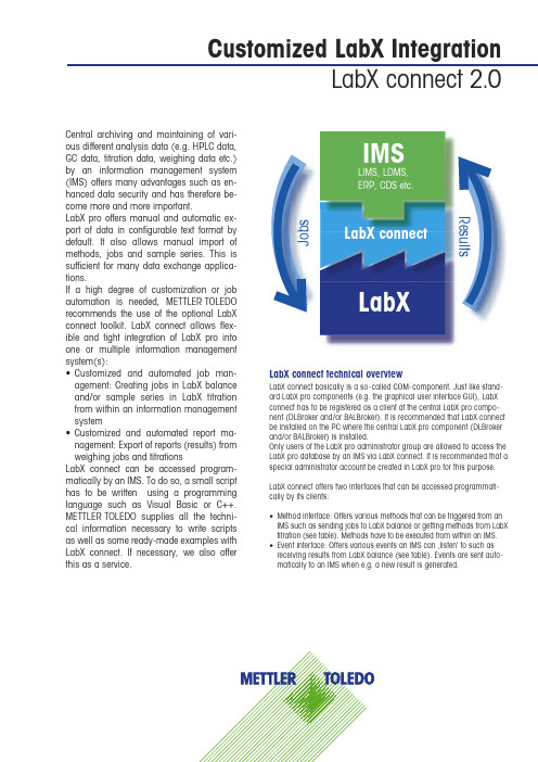
Customized LabX IntegrationLabX connect 2.0 Central archiving and maintaining of vari-ous different analysis data (e.g. HPLC data,GC data, titration data, weighing data etc.)by an information management system(IMS) offers many advantages such as en-hanced data security and has therefore be-come more and more important.LabX pro offers manual and automatic ex-port of data in configurable text format bydefault. It also allows manual import ofmethods, jobs and sample series. This issufficient for many data exchange applica-tions.If a high degree of customization or jobautomation is needed, METTLER TOLEDOrecommends the use of the optional LabXconnect toolkit. LabX connect allows flex-ible and tight integration of LabX pro intoone or multiple information managementsystem(s):• Customized and automated job man-agement: Creating jobs in LabX balanceand/or sample series in LabX titrationfrom within an information managementsystem• Customized and automated report ma-nagement: Export of reports (results) fromweighing jobs and titrationsLabX connect can be accessed program-matically by an IMS. To do so, a small scripthas to be written using a programminglanguage such as Visual Basic or C++.METTLER TOLEDO supplies all the techni-cal information necessary to write scriptsas well as some ready-made examples withLabX connect. If necessary, we also offerthis as a service.LabX connect technical overviewLabX connect basically is a so-called COM-component. Just like stand-ard LabX pro components (e.g. the graphical user interface GUI), LabXconnect has to be registered as a client at the central LabX pro compo-nent (DLBroker and/or BALBroker). It is recommended that LabX connectbe installed on the PC where the central LabX pro component (DLBrokerand/or BALBroker) is installed.Only users of the LabX pro administrator group are allowed to access theLabX pro database by an IMS via LabX connect. It is recommended that aspecial administrator account be created in LabX pro for this purpose.LabX connect offers two interfaces that can be accessed programmati-cally by its clients:• Method interface: Offers various methods that can be triggered from anIMS such as sending jobs to LabX balance or getting methods from LabXtitration (see table). Methods have to be executed from within an IMS.• Event interface: Offers various events an IMS can ‚listen‘ to such asreceiving results from LabX balance (see table). Events are sent auto-matically to an IMS when e.g. a new result is generated.LabXLabX connectLIMS, LDMS,ERP, CDS etc.IMSJobs ResultsSubject to technical changes© 09/2004 Mettler-Toledo GmbH Printed in Switzerland 51724384Marketing Analytical Chemistry Mettler-Toledo GmbH, Analytical CH-8603 Schwerzenbach, Switzerland Phone +41-44-806 77 11Fax +41-44-806 73 50Quality certificate ISO 9001Environmental management system ISO 14001Internet: Worldwide serviceMethod interfaceA LabX connect client (IMS) can call up a LabX connect method if this method has been implemented at the client. LabX connect methods that can be implemented include:Event interfaceA LabX connect client (IMS) can use the event interface of LabX connect if it has methods implemented for the offered events. LabX connect fires events to inform its registered clients about new results. The LabX connect event interface offers the follow-ing events:These events provide the following information for new,changed or restored data:。
软件系统集成实施作业指导书
软件系统集成实施作业指导书第1章项目概述 (4)1.1 项目背景 (4)1.2 项目目标 (4)1.3 项目范围 (5)第2章需求分析 (5)2.1 用户需求 (5)2.1.1 用户基本需求 (5)2.1.2 用户特定需求 (5)2.2 功能需求 (6)2.2.1 核心功能 (6)2.2.2 辅助功能 (6)2.3 系统功能需求 (6)2.3.1 响应时间 (6)2.3.2 数据处理能力 (6)2.3.3 系统容量 (6)2.3.4 系统稳定性 (6)2.4 系统约束条件 (6)2.4.1 技术约束 (6)2.4.2 业务约束 (7)2.4.3 资源约束 (7)第3章系统设计 (7)3.1 系统架构设计 (7)3.1.1 架构概述 (7)3.1.2 架构组件 (7)3.1.3 架构特点 (7)3.2 模块划分 (8)3.3 接口设计 (8)3.3.1 外部接口 (8)3.3.2 内部接口 (8)3.4 数据库设计 (8)3.4.1 数据库选型 (8)3.4.2 数据库表设计 (8)3.4.3 数据库索引设计 (8)3.4.4 数据库安全设计 (9)第4章系统开发 (9)4.1 开发环境准备 (9)4.1.1 硬件环境 (9)4.1.2 软件环境 (9)4.1.3 开发工具及软件版本 (9)4.2 编码规范 (9)4.2.1 代码命名规范 (9)4.2.3 版本控制 (10)4.3 系统开发流程 (10)4.3.1 需求分析 (10)4.3.2 设计阶段 (10)4.3.3 编码阶段 (10)4.3.4 测试阶段 (10)4.3.5 部署阶段 (10)4.4 系统模块实现 (10)4.4.1 用户管理模块 (10)4.4.2 业务处理模块 (10)4.4.3 数据管理模块 (10)4.4.4 系统监控模块 (10)4.4.5 辅助功能模块 (11)第5章系统集成 (11)5.1 集成策略 (11)5.1.1 总体规划 (11)5.1.2 分阶段实施 (11)5.1.3 优先级排序 (11)5.1.4 回归测试 (11)5.2 集成步骤 (11)5.2.1 需求分析 (11)5.2.2 技术选型 (11)5.2.3 设计集成方案 (11)5.2.4 开发与实施 (11)5.2.5 验收测试 (12)5.3 集成测试 (12)5.3.1 单元测试 (12)5.3.2 集成测试 (12)5.3.3 功能测试 (12)5.3.4 安全测试 (12)5.4 集成问题处理 (12)5.4.1 问题定位 (12)5.4.2 问题解决 (12)5.4.3 防范措施 (12)5.4.4 持续优化 (12)第6章系统测试 (12)6.1 测试计划 (12)6.1.1 目的 (12)6.1.2 范围 (13)6.1.3 测试资源 (13)6.1.4 测试策略 (13)6.2 功能测试 (13)6.2.1 目的 (13)6.3 功能测试 (14)6.3.1 目的 (14)6.3.2 测试内容 (14)6.4 安全性测试 (14)6.4.1 目的 (14)6.4.2 测试内容 (14)第7章系统部署 (14)7.1 部署策略 (14)7.1.1 总体部署规划 (14)7.1.2 部署步骤 (15)7.2 硬件环境准备 (15)7.2.1 硬件设备选型 (15)7.2.2 硬件设备配置 (15)7.2.3 硬件设备调试 (15)7.3 软件环境配置 (15)7.3.1 操作系统安装 (15)7.3.2 数据库安装与配置 (15)7.3.3 中间件安装与配置 (15)7.3.4 应用软件部署 (16)7.4 系统上线 (16)7.4.1 系统切换 (16)7.4.2 系统运维 (16)第8章用户培训与验收 (16)8.1 培训计划 (16)8.1.1 培训目标 (16)8.1.2 培训时间 (16)8.1.3 培训对象 (16)8.1.4 培训师资 (16)8.2 培训内容 (16)8.2.1 系统概述 (16)8.2.2 功能模块培训 (17)8.2.3 系统管理 (17)8.2.4 常见问题及解决方案 (17)8.2.5 安全防护 (17)8.3 培训方式 (17)8.3.1 理论培训 (17)8.3.2 实操培训 (17)8.3.3 在线培训 (17)8.3.4 互动交流 (17)8.4 系统验收 (17)8.4.1 验收标准 (17)8.4.2 验收流程 (17)8.4.3 验收内容 (17)8.4.5 验收结果 (17)第9章系统维护与优化 (17)9.1 系统维护策略 (18)9.1.1 维护目标 (18)9.1.2 维护内容 (18)9.1.3 维护流程 (18)9.2 故障处理 (18)9.2.1 故障分类 (18)9.2.2 故障处理流程 (18)9.2.3 应急预案 (19)9.3 系统优化 (19)9.3.1 优化目标 (19)9.3.2 优化内容 (19)9.3.3 优化流程 (19)9.4 版本更新 (19)9.4.1 版本更新原则 (19)9.4.2 版本更新流程 (19)第10章项目总结与评价 (20)10.1 项目总结 (20)10.1.1 项目实施过程回顾 (20)10.1.2 项目成果总结 (20)10.1.3 项目存在的问题 (20)10.2 项目评价 (20)10.2.1 项目目标评价 (20)10.2.2 项目质量评价 (21)10.2.3 项目效益评价 (21)10.3 项目经验积累 (21)10.4 改进措施与建议 (21)第1章项目概述1.1 项目背景信息化建设的不断深入,我国企业对于软件系统的依赖程度日益提高。
ERP系统使用说明书

目录ERP系统操作说明 (1)1、ERP简介 (1)2、登录系统 (2)3、系统管理模块 (2)4、生产管理模块 (6)5、财务工时 (10)6、库房管理模块 (11)7、资源管理模块 (14)8、订单管理模块 (16)ERP系统操作说明1、ERP简介近年来,ERP系统在全球范围内的企业里迅速推广实施并取得了巨大成功。
ERP作为一种新兴的企业管理理论和模式,以其先进的计划经营管理理念和高度集成的信息化管理等优点,正被越来越多的企业所接受和普遍应用。
初次接触ERP的人,首先都会出现疑问通常都是:“何谓ERP?”、“SAP 又是什么?”以及“PM模块有哪些功能及作用?”等等。
下面首先简单介绍一下ERP以及SAP的基本概念。
1.1、什么是ERP?ERP(Enterprise Resource Planning)就是“企业资源计划”,包括企业内部资源和外部资源。
内部的资源如,人力资源、物料资源、资金资源、时间资源,外部的包括客户资源、供应商资源等。
ERP就是将这些资源整合,从而使企业的采购、生产、销售、库存等得到优化管理。
ERP系统是一套集成了ERP管理理念与企业具体业务流程、借助于ERP计算机应用软件来实现新型企业管理模式的企业资源管理系统。
用以支持企业主要的核心业务流程,通常包括:财务会计、生产计划、销售分销、物料管理、工厂维护、人力资源等;整体、实时地提供与各项业务相关的数据,包括以前难以及时获取的数据;可以向领导者提供企业整体的状况,反映企业的盈利能力和各项业务活动的情况;所有业务处理和活动通过统一的数据库进行及时更新,以改善用户存取、提高业务信息质量、减少数据校验,内嵌了可配置的行业最佳业务模式。
1.2、什么是ERP系统?ERP系统集成了ERP管理理念与企业具体业务流程、借助于ERP软件对企业的多种资源进行计划,以物流、资金流、信息流 (“三流”) 合一的高度集成方式来帮助企业实现自动化管理模式的资源管理系统,用以支持企业主要的核心业务流程,通常包括:财务会计、生产计划、销售分销、物料管理、工厂维护、人力资源等。
(完整版)软件系统详细设计说明书模板

(完整版)软件系统详细设计说明书模板xxxxx系统详细设计说明书版本历史修改记录⽬录1引⾔ (5)1.1编写⽬的 (5)1.2背景 (5)1.3参考资料 (5)1.4术语定义及说明 (5)2设计概述 (5)2.1任务和⽬标 (5)2.1.1需求概述 (5)2.1.2运⾏环境概述 (5)2.1.3条件与限制 (6)2.1.4详细设计⽅法和⼯具 (6)3系统详细需求分析 (6)3.1详细需求分析 (6)3.2详细系统运⾏环境及限制条件分析接⼝需求分析 (6)4总体⽅案确认 (6)4.1系统总体结构确认 (6)4.2系统详细界⾯划分 (7)4.2.1应⽤系统与⽀撑系统的详细界⾯划分 (7) 4.2.2系统内部详细界⾯划分 (7)5系统详细设计 (7)5.1系统程序代码架构设计 (7)5.1.1UI(User Interface)⽤户界⾯表⽰层 (7)5.1.2BLL(Business Logic Layer)业务逻辑层 (8) 5.1.3DAL(Data Access Layer)数据访问层 (8) 5.1.4Common类库 (8)5.1.5Entity Class实体类 (8)5.2系统结构设计及⼦系统划分 (8)5.3系统功能模块详细设计 (9)5.3.1XX⼦系统 (9).1XX模块 (9)列表和分页 (9)创建XX (9).2XX模块 (9)XX列表 (9)XX修改 (9)5.3.2XX⼦系统 (9)5.3.6.1⽤户管理模块 (9)5.3.6.2⾓⾊管理模块 (14)5.3.6.3系统设置模块 (14)5.3.6.4系统登录注销模块 (14)5.4系统界⾯详细设计 (14)5.4.1外部界⾯设计 (14)5.4.2内部界⾯设计 (14)5.4.3⽤户界⾯设计 (14)6数据库系统设计 (14)6.1设计要求 (14)6.2信息模型设计 (14)6.3数据库设计 (14)6.3.1设计依据 (14)6.3.2数据库种类及特点 (15)6.3.3数据库逻辑结构 (15)6.3.4物理结构设计 (15)6.3.5数据库安全 (15)6.3.6数据字典 (15)7信息编码设计 (15)7.1代码结构设计 (15)7.2代码编制 (15)1引⾔1.1编写⽬的说明编写详细设计⽅案的主要⽬的。
IEC 61850标准的电力自动化系统集成与效率提高方法说明书

THE POWER OF INFORMATION INTEGRATION IN INDUSTRIALAUTOMATION ALLIED TO IEC 61850How to make industrial automation to be more efficient, using information to integrate Process andElectrical Automation systems based on IEC 61850 StandardAlan Fernandes Teixeira 1and Leandro Henrique Monaco 21Alan Fernandes Teixeira is application engineer of electrical automation at the mining segment on Process Automation division in ABB Brazil, and he’s graduated in Electrical Engineering – Electrotechnics on São Judas Tadeu University. 2Leandro Henrique Monaco is electrical automation engineering manager at the mining segment on Process Automation division in ABB Brazil, and he’s graduated in Electrical Engineering – Automation and Control and Master of Science in Systems Engineering by Polytechnic School of University of São Paulo.1 – IntroductionA substation automation system is basically composed of elements to protect equipment, to control switches, circuit breakers and transformers, as well as supervision and monitoring of the status from all involved equipment, respecting each equipment features and possible limitations.There are two typical scenarios when it comes to substation automation: the first relates to new plants, in which the designer can create a concept for the plant automation, define the best network and infrastructure topology, in order to mitigate the risks, get complete information of the electrical system and optimize the system implementation costs; but there is also the second scenario, where existing plants are in production (some for many years) and without dedicated infrastructure to electrical automation. In these plants it is common to find several automation systems for each substation, using usually PLCs, supervisory systems from various vendors with little or no information exchange because, as a rule, there isn’t a central system that manages all substations, making plant control and management to be much harder.In these days, it’s essential to have an automation system capable of integrating all available information into a single platform, regardless of the model chosen for a particular protection relay or the chosen protocol, and making information available anywhere in the plant so as to facilitate remote operation. Moreover, the possibility of integrating the substation automation system to the process control system enables a single database and complete plant management, both for operation and maintenance.Figure 1. Leandro Monaco and Alan Fernandes: "It’s essential to have an automation system capable of integrating all available information into a single platform".2 – Electrical Automation Integrated System2.1 IEC61850 standardWith the evolution of substation equipment, such as IEDs (Intelligent Electronic Devices) and digital meters, and with the advent of IEC 61850, the possibility of having the equipment integration from different vendors in a single system becomes reality. In the case of plants in production, such integration allows several substations with IEDs from different vendors to be grouped into a single system, because they all speak "the same language". This makes operation and maintenance of the electrical system to be easier, bringing information from the whole plant. This is called interoperability.IEC 61850 standard can be misunderstood as a communication protocol; however, it goes far beyond that. In order to standardize the complete communication concept in substation automation, the standard is based on three goals: interoperability; freedom of configuration and long-term stability. Interoperability is the ability for IEDs from different vendors to communicate with each other; freedom of configuration is the ability of each vendor to use different methods and philosophies in the internal programming of the logic performed by IEDs, as long as the data exchange between them obey the goal of interoperability, and concerns the freedom to allocate functions to one or more IEDs during the substation project by the engineering team; and long-term stability refers to the ability of communication protocols to remain updated in front of technological advances.For that, the way devices exchange data is standardized, using the concept of Logical Node. According to its definition, a Logical Node is "the smallest part of a function that exchanges data" (IEC 61850-SER ed1.0, 2010). Each substation function is broken into smaller parts, and data exchanged between each part is standardized, without affecting the inner operation of each part. This ensures interoperability and freedom of configuration.In order to allow information exchange between devices, two communication protocols are defined: one for communication between IED and supervisory system, called MMS; and another for fast communication between IEDs for interlocks and logic selectivity, called GOOSE. MMS protocol (Manufacturing Message Specification) is used for communication between IEDs and supervisory system based on client-server philosophy, i.e., the IED becomes a server for the information available in it and the supervisory system becomes a client for that information; it is used for supervision and operation information, being a non-critical time communication. GOOSE protocol (Generic Object Oriented Substation Events) is used to exchange the critical time information between IEDs inside network for protection, interlocking and logic selectivity purposes; this communication is based on MAC addresses, and allows the transmission of packets in the network as fast as 3 ms. GOOSE protocol is one of the great advantages of IEC 61850, reducing the amount of wiring between cubicles of a substation to perform logic selectivity schemes, greatly reducing installation and maintenance costs.All communication between the devices is over Ethernet network protocol, globally known in enterprise environments and now also in the industry ones. At this point, it’s important to notice the importance of network configuration on an industrial project. Today it is no longer possible to foresee an industrial scenario without communication possibilities offered by industrial networks. The need for information integration (achieved long ago in IT scenarios) becomes crucial in industrial scenarios, and will become increasingly essential in the near future.Figure 2 presents a generic topology that addresses the minimal concepts of an electrical automation project. One can see the substation equipment such as circuit breakers, switchgears etc., (given by iPASS Switchgear boxes) as well as measuring instruments like CTs and VTs (MUPX and MUPY boxes), physically connected to the protection and control IEDs (given by boxes Bay Controller, Prot X and Prot Y), which are connected to an Ethernet switch. The switches of each substation are part of a network that is connected to protocols gateways and to human-machine interface equipment (HMI). GPS devices are also commonly used to synchronize time on the IEDs in order to allow the sequence of events (SoE).Figure 2-Network Topology of the Automation System in IEC 61850.2.2 Advantages for the electrical systemAs the intelligence for protection and logic selectivity is distributed to the IEDs (which can now communicate with each other), the DCS can be in charge of power management and other logics that require a higher level system view. Some functions such as load shedding, generator control, turbine management, transformer tap control can be run on the DCS, and some controllers have GOOSE interface, achieving operating times faster than 10 ms, thus reducing selectivity adjust times, taking care of mechanical health of cabling, circuit breakers, switchgears and machines, without using hardwires.Another great advantage with the advent of IEC 61850: a trend of all equipment in the electrical system to suit the communication according to IEC 61850, which initially started only in IEDs. Today we already have digital meters, and soon CTs and VTs will emerge in the market with communication drivers, plus circuit breakers and switchgears, i.e., it will be possible to see the system more and more integrated, through a single standard of network connection and the electrical system itself.3 – Case study: Itabira integrated systemIn order to show how the information integration brought by the use of IEC 61850 concepts, especially interoperability, some features of a real system already implemented are here illustrated. This section is about the electrical automation integrated system of Itabira, the iron ore beneficiation plant located in the city of Itabira-MG, Brazil. In this system, six main substations were integrated into a single system, providing information ofhigh voltage equipment such as 230 kV and 69 kV up to medium voltage as 13.8 kV and 4.16 kV. The six substations are located in different places around the city, separated by distances up to 30 km from the central operating room. The IEDs are from two different vendors, due to the fact that substations retrofits were made at different periods and under different contracts.The supervisory system is from a third vendor, and it communicates with the IEDs via MMS protocol for system operation and supervision. Moreover, due to the large distance between the substations and the risk of losing communication, it was used a contingency operation solution in each substation, consisting of a human-machine interface touch screen panel and a controller with GOOSE interface, being able to receive data from and send commands to the IEDs, in order to ensure remote operation of circuit breakers and switches. This guarantees the main project concept: to keep the operator away from the electrical cubicle, and consequently from the electrical risk.Figure 3 illustrates the generic automation system topology used in Itabira. One can see how the two interfaces of the automation system to the IEDs, using both protocols proposed by IEC 61850.Figure 3. Automation System Network Topology, with two interfaces to IEC 61850 devices.Due to greater amount of information available in the IED network because of digital communication protocols (IEC 61850 network in Figure 3, for better understanding), besides the possibility of communication between IEDs from different vendors located in substations away from each other, it was possible to get an integration level of all the available information in the same system, so the electrical system operation is possible regardless of where the operator is. The information centralization through Ethernet networks also allowed creating a remote operating room, from where there is view of everything that’s happening in the system. Moreover, system maintenance also become easier because the IEDs can be parameterized and configured from anywhere with access to the automation system, and if it’s necessary to go to the failure spot, the technician will be able to get there with more details about what happened. So the three main project concepts were achieved: remote operation guaranteed; remote maintenance; and integration of information in a single system.4 – Electrical and Process automation integration on the same systemThe adoption of Ethernet-based systems makes open protocols to be used more often, creating more complete automation systems, thus optimizing costs and information availability on the entire plant.In the past, and in many plants in operation nowadays, there is still a strong separation between the electrical automation system, responsible for power management, and the process automation system, more focused on the production, in a way that there is little or no exchange of information between them. Today one can understand it’s an increasing trend to have a single system managing the entire plant, looking for both Process and Electrical automation with excellent performance and availability through a unique DCS system.Figure 4 presents a topology that can best show the new model.Figure 4. Integrated Topology for Process and Electrical Automation Systems, using IEC 61850.4.1 Advantages for the process control systemAmong the advantages that can be pointed from this integration, cost reduction is the first one, because servers, software and hardware are optimized. Besides that, indirect costs such as training and investment shared between areas. In addition, new features can be implemented from the combination of information.An example of this possibility is the adoption of medium voltage protection relays for motors control in IEC 61850, in which it’s possible to use all the benefits of GOOSE messages between IEDs without losing the interaction with process equipment, such as instrumentation, valves, and inverters.A real case for this functionality can be given by a conveyor that handles ore, steel or any other goods.Usually in these cases, big medium voltage motors are responsible for the operation, and if one of them failures the replacement won’t be immediate, causing damage and loss of production. Using features from substation automation environment, like logic selectivity and interlocks, it’s possible to preserve their health.Here are some pictures that illustrate how these features can be applied.Figure 5. Conveyor motors interlocking according to a traditional fashion.Figure 6. Conveyor motors interlocking using IEC 61850.Figures 5 and 6 show that using IEC 61850 it is possible to switch off motors before overcurrent effects are detected by CTs, lowering the impact on the motors, thus increasing their life cycle. This reduces the chances of damaging windings or more serious problems that would demand replacement and longer maintenance time, resulting in loss of production for longer periods.5 – ConclusionThe availability and the quality of information are assumptions that guide the day-by-day, increasing the level of demand in all areas including the industrial environment, and causing dramatic changes in established practice that are becoming obsolete.With the advent of IEC 61850, more information is collected from the electrical automation system, due to Ethernet communication and data standardization, enabling interoperability, allowing free choice of IED vendors in order to best suit the substation environment. And with such a wealth of data available in supervisory systems, the information integration between automation systems allows multidisciplinary decisions to be taken by putting together the electrical control with process control needs. This provides more efficiency and bigger production availability, current concerns in the competitive global market. Moreover, applications developed typically for electrical environment can be used in process control system, which can be seen in the examples given.In this scenario one can assure the advent of IEC 61850 provided a huge evolution in quality, changing the way we think of automation: automation based on the information integration.6 – ReferencesIEC 61850-SER ed1.0: Communication networks and systems in substations - ALL PARTS; Switzerland: International Electrotechnical Commission, 2010. MONACO, L.H. Integração com IEC61850 – Fluxo de Engenharia. In: 13º. Seminário de Automação de Processos ABM 2009, São Paulo, Brazil, Set 2009 (in Portuguese)MONACO, L. H. Estudo de caso: sistema integrado de automação de subestações usando a norma IEC61850 aplicado na usina da Vale Itabira-MG. In: 15º Congresso Internacional de Automação, Sistemas e Instrumentação, Brazil Automation ISA 2011, São Paulo, Brazil, 8-10 Nov 2011 (in Portuguese).。
- 1、下载文档前请自行甄别文档内容的完整性,平台不提供额外的编辑、内容补充、找答案等附加服务。
- 2、"仅部分预览"的文档,不可在线预览部分如存在完整性等问题,可反馈申请退款(可完整预览的文档不适用该条件!)。
- 3、如文档侵犯您的权益,请联系客服反馈,我们会尽快为您处理(人工客服工作时间:9:00-18:30)。
中北大学课程设计说明书学生姓名:学号:学院:专业:题目:2015 年 7 月 1 日目录1 课程设计目的 (1)2 课程设计内容和要求 (1)2.1 设计内容 (1)2.2 设计要求 (1)3 设计方案及实现情况 (1)3.1 设计方案及论证 (1)3.1.1 DC-DC主回路拓扑 (1)3.1.2 控制方案选择 (2)3.2 工作原理及框图 (2)3.2.1 Boost升压主电路 (2)3.2.2开机保护电路 (4)3.2.3开关管保护电路 (4)3.2.4 输出滤波和输出过流保护 (4)3.2.5 KL26主控电路及采集 (5)3.2.6 键盘输入及显示 (6)3.3 效率分析及计算 (6)3.4 硬件电路原理图 (7)3.5 仿真分析 (7)3.6 PCB版图设计 (8)3.7 系统测试 (8)3.7.1测试使用的仪器 (8)3.7.2测试方法 (8)3.7.3测试数据 (9)3.7.4 指标完成 (9)4课程设计总结 (9)参考文献 (9)1 课程设计目的1.学习操作数字电路设计实验开发系统,掌握开关电源的工作原理。
2.掌握C语言开发设计,熟悉单片机的工作原理。
3.掌握基于单片机系统的开发设计。
2 课程设计内容和要求2.1 设计内容设计并制作一个开关稳压电源。
输入220V交流电,输出30V~36V可调直流电。
通过液晶屏显示。
2.2 设计要求基本要求:(在电阻负载条件下,使电源满足下述要求)1、输出电压U O可调范围:30V~36V;2、最大输出电流I Omax:2A;3、U2从15V变到21V时,电压调整率S U≤2%(I O=2A);4、I O从0变到2A时,负载调整率S I≤5%(U2=18V);5、输出噪声纹波电压峰-峰值U OPP≤1V(U2=18V,U O=36V,I O=2A);6、DC-DC变换器的效率≥70%(U2=18V,U O=36V,I O=2A);发挥部分:1、进一步提高电压调整率,使S U≤0.2%(I O=2A);2、进一步提高负载调整率,使SI≤0.5%(U2=18V);3、提高效率,使效率≥85%(U2=18V,UO=36V,IO=2A);4、能对输出电压进行键盘设定和步进调整,同时显示输出电压电流。
3 设计方案及实现情况3.1 设计方案及论证3.1.1DC-DC主回路拓扑方案一:图1是间接直流变流电路:结构如图1-1所示,可以实现输出端与输入端的隔离,适合于输入电压与输出电压之比远小于或远大于1的情形,但由于采用多次变换,电路中的损耗较大,效率较低,而且结构较为复杂。
图1 间接直流电路方案二: Boost 升压斩波电路:拓扑结构如图1-2所示。
开关的开通和关断受外部PWM 信号控制,电感L 将交替地存储和释放能量,电感L 储能后使电压泵升,而电容C 可将输出电压保持住,输出电压与输入电压的关系为UO=(ton+toff),通过改变PWM 控制信号的占空比可以相应实现输出电压的变化。
该电路采取直接直流变流的方式实现升压,电路结构较为简单,损耗较小,效率较高。
(如图2)图2 boost 升压电路综合比较,我们选择方案二。
3.1.2 控制方案选择方案一:利用PWM 专用芯片产生PWM 控制信号。
此法较易实现,工作较稳定,但不易实现输出电压的键盘设定和步进调整。
方案二:利用KL26单片机产生PWM 控制信号。
让单片机根据反馈信号对PWM 信号做出相应调整以实现稳压输出。
这种方案实现起来较为灵活,可以通过调试针对本身系统做出配套的优化。
但是系统调试比较复杂。
我们选择方案二 。
3.2 工作原理及框图 3.2.1 Boost 升压主电路图3是Boost 升压电路包括驱动电路和Boost 升压基本电路。
电力晶体管(GTR )耐压高、工作频率较低、开关损耗大;电力场效应管(Power MOSFET )开关损耗小、工作频率较高。
从工作频率和降低损耗的角度考虑,选择电力场效应管作为开关管IRF540。
选择ESAD85M-009型肖特基二极管,其导通压降小,通过1 A 电流时仅为0.35V ,并且恢复时间短。
实际使用时为降低导通压降将两个肖特基二极管并联。
R L(1) 电感值的计算:()22OO IN O INBfU mI U U U L -=其中,m 是脉动电流与平均电流之比取为0.25,开关频率f=20 kHz,输出电压为36V 时,L B =527.48μH ,取530μH 。
电感线径的计算:最大电流I L 为2.5A ,电流密度J 取4 A/mm 2,线径为d,则由L I d J =22*)(π得d=0.892 mm,工作频率为20kHz,需考虑趋肤效应,制作中采取多线并绕方式,既不过流使用,又避免了趋肤效应导致漆包线有效面积的减小。
(2)电容的参数计算:OO IN O O B U f U U U I C ∆-=)( 其中,ΔU O 为负载电压变化量,取20 mV,f=20kHz,U O =36V 时,C B =1465μF,取为2000μF ,实际电路中用多只电容并联实现,减小电容的串联等效电阻(ESR ),起到减小输出电压纹波的作用,更好地实现稳压。
(3)boost 损耗计算:输出电流有效值)(D D I I IN RMS O -⨯⨯=-113.1 代入数据得 I O-RMS =2.069 A而电容的损耗 2/21ESR I P RMS O CO ⨯=-等效串联电阻ESR 取为10 m Ω,代入得P CO1=0.0428 W图 3 主回路3.2.2开机保护电路在直流输入端串联一支保险丝(250V,5A),从而实现过流保护,反接保护功能由二极管和保险丝实现。
用NTC电阻实现了对开机浪涌电流的抑制,当上电瞬间,电阻很大,从而对其防止浪涌电流产生。
(如图4)图4 开机保护电路3.2.3开关管保护电路利用IR2302的欠压保护功能,对其电源电压进行检测,当电压达到200mv 的时候比较器输出高电平,使IR2302的SD管角接高电平,从而使场效应管严格工作在非饱和区或截止区,防止场效应管进入饱和区而损坏,为了防止尖峰电流的产生使芯片误判,我们采用逐波防锁电路。
(如图5)图 5 开关管保护电路3.2.4输出滤波和输出过流保护我们采用电感和电容进行滤波,效果比只使用电容好,我们通过康铜丝采集电流。
当电流超过2.5A的时候打开继电器。
从而关闭电源。
输出端串接电流采样电阻R TEST2,材料选用温漂小的康铜丝。
电压信号需放大后送给单片机进行A/D 采样。
过流故障解除后,系统将自动恢复正常供电状态。
为了降低纹波,采用LC 低通滤波器如图6。
取截止频率f L =200 Hz ,电容取470μF ,由Cf L L 241π=LCf L π21=代入得L=215.80 μH ,取220μH图 6 过流保护电路3.2.5 KL26主控电路及采集单片机根据电压的设定值和电压反馈信号调整PWM 控制信号的占空比,实现稳压输出,同时,单片机与采样电路相结合,将为系统提供过流保护、过热保护、过压保护等措施,并实现输出电压、输出电流和输入电压的测量和显示。
PWM 信号占空比OIN U U D -≈1 ;当U2=15V ,UO=36V 时,U IN =1.2*U 2-2V=16V , 最大值D MAX =0.556; 当U2=21V ,UO=30V 时,U IN =1.4*U 2-2V=27.4V ,最小值D MIN =0.087系统对于单片机A/D 采样精度的要求:题目中最高的精度要求为0.2%,欲达到这一精度,A/D 精度要达到1/500,即至少为9位A/D ,MP430内置A/D 为12位,只要合理设定测量范围,完全可以达到题目的精度要求。
3.2.6 键盘输入及显示分别通过键盘和LCD 实现数字设定和显示。
键盘用来设定和调整输出电压;输出电压、输出电流和输入电压的量值通过LCD 显示。
3.3 效率分析及计算(U 2=18V,输出电压U O =36V,输出电流I O =2A )DC-DC 电路输入电压U IN =1.2*U 2-2V=19.6V ,信号占空比D ≈1-U IN /U O =0.456, 输入电压有效值I IN =I O /(1-D )=3.676A , 输出功率P O =U O *I O =72 W 下面计算电路中的损耗P 损耗:Boost 电路中电感的损耗:121DCR I P IN DCR ⨯=,其中,DCR 1为电感的直流电阻,取为50 m Ω,代入可得P DCR1=0.68 W Boost 电路中开关管的损耗开关损耗:P SW =0.5*U IN *I IN (t r +t f )*f其中,t r 是开关上升时间,为190ns,t f 是开关下降时间,为110ns,f 是开关频率,为20 kHz,代入可得 P SW =0.2160 W导通损耗))((SNS D SO N INC R R ID P +⨯=3.12其中,导通电阻R DSON =77 m Ω,电流感应电阻R SNS 取0.1 Ω,代入得P C =1.23 W 肖特基二极管的损耗流过二极管的电流值与输出电流I 0相等,则二极管损耗D O D V I P =,其中,I O =2 A,取二极管压降V D 为0.35 V ,代入可得P D =0.7 W 两只采样电阻上的总损耗为0.9 W ,综上,电路中的总损耗功率P 损耗=4.5WDC-DC 变换器的效率η= P O /(P O +P 损耗)=94%3.4 硬件电路原理图图7 为整个系统的电路原理图。
图7 总电路图3.5 仿真分析图8采用multisim对主回路仿真,通过示波器查看输出电压,进过比对,和理论值相近。
改变信号源的占空比,输出电压发生变化。
图8仿真设计3.6 PCB 版图设计图9采用AD11进行电路板设计,采用手工布线和自动布线相结合设计。
对控制信号进行覆铜,防止大电流干扰。
(1) 电源线宽和地线宽采用80mil 。
信号线采用18mil 。
(2) 对主回路和控制信号分开覆铜。
图 9 PCB 板3.7 系统测试3.7.1测试使用的仪器表1 列出了测试中所需的仪器和数量。
3.7.2测试方法图10 为整个电路系统的测试点。
L2图10 测试连接图3.7.3测试数据(1)电压调整率(测试条件:IO=2A,UO=36V)。
U 2=15V时,UO1=35.98V;U2=21V时,UO2=36.13V,压调整率SU=(UO2-UO1)/(O1=0.42%)(2)负载调整率SI测试(测试条件:U2=18V,UO=36V)。
I O =0A时,UO3=36.29V;IO=2A时,UO4=36.04V,载调整率SI=(UO3-UO4)/UO3=0.69%。