ASME第八卷第一册_UCS-56焊后热处理要求(2007版)
ASME Ⅷ1卷《压力容器建造规则》中关于材料的防脆断措施分析与理解
处理 虽然这-规定并不是针对低温容器 " 但是低温容器 " 更应 注意该项规定
4 .3 压力试验方面的控制措施
SME VlII- J 标准 UG- 99 01) 、 UG- lOO(c) 中规定 , 在液压或气压
试验时容器金属温度至少应保持在容器所允许的最低设计金属温
低应力条件下时无疑可以改善其防脆断性能也就是最低金属温
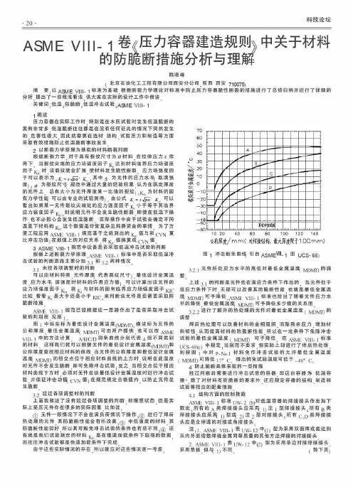
应力场强度因子 比 ,将 K, 与材料的固有 1悔界应力炀强度因子 阳C 比较,看 看 凡 是大子还是小子 K1C , 来判断该元件是否需要采取防
跪断措施
乓 MDMI丁 可予降低 , ASME VllI- 1 标准也给出了随着元件应力水
平的降低,最低金属温乓 阳MT丁 可予降低多少值的关系图 。 3 .2.2 进行了额外的热处理的元件对最低金属温度 ( MDMη 的
热处理的元件 , 其防脆断性能会有所改善: @ 中低强度的材料.其
地阳V1U- 1 标准 肌 2. (b) 对低温容器的焊接接头作出如下 限定:所奋的 A 类焊接接头应巢用 。 注 l 型焊接接头:所有 B 类 焊接接头应采用 1 ) 型玛 2) 注 2 型对接接头 ; 所有 c、 D 类焊接接
头应是全焊透的对接或角接接头 。
则按图 l 中对 p- NO. l 材料免作冲击试验的允许最低金属温度
4 防止脆断具体采取的一些措施 经过判断后需要进行冲击试验的窑器 RP 这台容器为低温容
温乓 阳刚 的徊交点位于相应材料曲线的上方时 , 说明在此温度 ( MDMη 可降低 1 7' C。 得出的免试验温度可低于 - 48 0 C.
的材料 。 这样我们就可以根据元件的最低设计金属温度 (MDMη和
ASME问答
“ASME压力容器和高温材料标准报告会”问题答复2007年5月30日至31日中国机械工程学会压力容器分会、中国动力工程学会、上海市机械工程学会压力容器与管道专业委员会和美国机械工程师学会北京代表处联合主办了“ASME压力容器和高温材料标准报告会。
会上,美国机械工程师学会压力容器技术委员会副主席、材料技术委员会副主席和标准与规范部负责标准开发与制定的执行主任做了专题报告。
与会代表向ASME委员会的专家们提出了许多问题,ASME专家回去后作了研究并给出了答复,现我会将答复的内容在网上公布,仅供有关人员参考。
问题及其答复问题1-1:在锅炉材料性能验收时,高温持久性能如何检验,因为锅炉设计中,高温持久性能是决定许用应力的主要指标?(SSEC)答复:拉伸试验需要根据ASME规范中材料规范(SA-XXX或SB-XXX)来确定,在建造规范中没有提出附加的拉伸试验要求。
问题1-2:按规范设计所使用的材料其冲击功值及冲击试验温度是如何给定的?如使用SA-516 Gr.70板,设备的设计温度分别为-30℃、-20℃、200℃,这时采购此材料时须提材料采购规范,那么采购规范应如何给出冲击值及冲击试验温度?(SSEC)答复:根据SA-20通用要求中的第4节,订货要求,其中的第4.1.6段,有对冲击试验的要求。
冲击试验要求在建造规范中有提及,例如第八卷中图UCS-66提供了冲击试验免除的方法。
问题1-3:ASME 2004版开始规定UNS N08811(Incoloy 800HT)的许用应力在650℃以上开始,比2001版向下修正,其背景或原因是什么?答复:版本修改的批准编号为89-028,“f"系数用来降低应力值,可参考SC II-D篇附录1问题1-4:UNS N08811许用应力温度上限到898℃,实际在900℃以上工程实际应用很多,怎样考虑许用应力?答复:在SC II-D的附录5中,给出了提高最高温度时所适用的极限值要求。
ASME 第八卷

鞍座:扩展筒体上的载荷,一个固定,一个滑动 强度、壁厚,经济性是封头选择的原因
小的立式容器使用支腿支撑 支腿长度、筒体直径≤2:1,再高就需要支耳了,耳座 支腿的个数尺寸和附件取决于受力、载荷 接管应用于:管道系统、测试接管、人孔、附属其他设备 法兰一般是焊接的,有时候伸出在容器上。 裙座支撑应用于高塔容器,柱状筒体,一般设在水平面上。
MAWP
最大设计压力,MAWP。MAWP≥设计压力,指定 温度=设计温度 容器的MAWP取决于最薄弱的元件。最初是取决于 新的厚度,无腐蚀情况;后来则取决于实际的将 来腐蚀情况下的载荷。
强调MAWP是界定与提供的元件厚度。壁厚需要包 括允许的腐蚀和壁厚承受的其他载荷
局部载荷:管道系统,梯子平台、内部结构、、 附加设备,支撑附件。 其他一些来评估局部载荷的规范(WRC107、297) 容器内部元件:塔盘,入口分液器,防涡流挡板, 催化剂床,支撑梁,出口集液器,分流网。旋风 分离器和增压系统。 ASME规范没有设计到内部构件的设计。
材料选择
应力:由于外力作用,材料每单位面积上的反抗 力/抵抗力。 压力容器设计保持应力在安全范围内。 最大许用应力,安全系数,随材料和温度的不同 而不同 ASME的最大许用应力是通过材料手册的。 II-D附录I,包含了除螺栓外的材料的许用应力的标 准。 II-D有一个许用应力表。
材料选择
这个表是由材料的化学组成和材料的组成分组的。 注意许用应力和设计温度的关系。在650F以上时, 大多数铁素体材料有一个相似的许用应力曲线。 注意热处理对断裂韧性的影响。两种情况下MDMT 和CET的关系。 以经济性和材料性能来选择材料的种中。 在元件厚度计算时用到。 注意腐蚀裕量。
ASME专家答复
2007 "ASME研讨会-上海"相关问题及专家答复说明: 2007年5月,在上海工程公司,由上海压力容器与管道专业委员会主办了一次“ASME 研讨会”,与会人员向来作报告的美国专家提出了很多问题,经他们回去研究讨论后,给予了答复。
如果对所作答复仍有异议,请直接与美国专家联系,联系方式在会议所发资料上可以找到。
问题1-1:在锅炉材料性能验收时,高温持久性能如何检验,因为锅炉设计中,高温持久性能是决定许用应力的主要指标?(SSEC)Question1-1:How to examine the high temperature strength limit of material in accepting the material used for constructing boiler in view of that the high temperature strength limit is the key parameter to determine the allowable stress in boiler design?Answer: Tensile testing should be in accordance with the ASME material specification (SA-XXX or SB-XXX). The construction Codes do not provide additional tensile testing requirements.答复:拉伸试验需要根据ASME规范中材料规范(SA-XXX或SB-XXX)来确定,在建造规范中没有提出附加的拉伸试验要求。
问题1-2:按规范设计所使用的材料其冲击功值及冲击试验温度是如何给定的?如使用SA-516 Gr.70板,设备的设计温度分别为-30℃、-20℃、200℃,这时采购此材料时须提材料采购规范,那么采购规范应如何给出冲击值及冲击试验温度?(SSEC)Q1-2:How to specify the impact energy and impact test temperature of the material in the Code? When using SA516 Gr.70,the design temperature of the item respectively is -30℃,-10℃and 200℃,according to the QC procedure ,it is necessary to prepare the purchasing specification, how to specify the impact energy and impact test temperature in the purchasing specification?Answer: Follow the guidelines provided in the referenced general specification SA-20 section 4 Ordering Information para. 4.1.6 on impact test requirements. Impact testing requirements are covered in the construction Codes. E.g. SC VIII Fig. UCS-66 provides impact test exemptions.答复:根据SA-20通用要求中的第4节,订货要求,其中的第4.1.6段,有对冲击试验的要求。
Ⅷ 1产品设计制造检验

Ⅷ-1产品设计制造检验自公司03年取得美国ASME U产品钢印和授权证书以来,公司已制造U钢印产品80余台,中圣在国际化道路上取得了长足的发展。
本次培训结合这些年的制造经历,并与GB-150进行比较,重点讲解Ⅷ-1有特色的部分内容。
1、许用应力及安全系数几十年来ASME规范按规则设计的安全系数一直取4.0,直到98版规范安全系数由4.0降为3.5,使材料许用应力提高12.5%。
材料的许用应力可以从第Ⅱ卷D篇中查取。
D篇有公制版和英制版两个版本。
表1A 对应铁基材料最大许用应力表1B 对应非铁基材料最大许用应力表3 对用螺栓材料最大许用应力D篇所列材料的排序按合金含量递增排列:碳钢——铬钼钢——不锈钢在同一“公称成份”以内,材料顺序按抗拉强度递增排序。
2、材料使用限制所有受压件材料都必须是ASME规范材料,且是Ⅷ-1卷表UCS-23、UHA-23或UNF-23中所列材料。
特殊情况下可选用Code Case材料。
非受压件材料可以选用其他国家标准材料,但要考虑可焊性。
焊接材料选用ASME规范、GB等材料均允许。
3、接头系数ASME规范Ⅷ-1关于接头系数的规定比GB和EN标准要复杂得多,也不易掌握。
UW-12关于接头系数的描述,归纳起来有以下要素:1) 接头系数取决于该接头的型式及探伤比例。
2) 接头型式有8种。
常用3种:1型双面对接、2型单面对接加垫板、3型单面对接不加垫板。
3) UW-12(d) 对无缝筒节环向应力计算或无缝封头厚度计算当符合UW-11(a)(5)(b)要求时E=1.0,不符合时,E=0.85。
4) C、D类角接头没有焊缝系数。
锥体与筒体连接<30°为对接接头,否则为角接接头。
插HSB讲课幻灯片补充实例A:在运用UW-11(a)(5)(b)时注意:(1)无缝筒体与封头连接(2)有缝筒体与封头连接当(1)(2)中B缝进行抽拍RT时,封头壁厚计算E=1.0当半球形封头与筒体连接时图示所有焊缝均为Cat. A 故环焊缝也应100%RT,而按(1)(2)依据UW-11(a)(5)(b)则错,(UG-31)补充B:ASME换证产品储罐采用Spot RT设计要求人孔法兰与筒节焊缝应抽查RT,由于该接头无焊接系数,不需要RT。
asme锅炉与压力容器规范第viii卷--压力容器.
对于周向或环向应力:
t = PR SE − 0.6P
对于纵向或轴向应力:
t = PR 2SE + 0.4P
式中
t —— 所需的最小厚度(in) P —— 最高许用工作压力或设计压力(lbf/in2) R —— 圆筒的内半径(in) S —— 设计温度下的最大许用拉应力值(lbf/in2) E —— 系数,选取焊缝系数与孔桥系数的较低值,
如果压力容器是由认可的U2硬印许可证持有者按照第Ⅷ卷第2册 的规定制造与检验的,该容器就可以取得具有U2标志的合格证 书,并在产品上敲盖U2硬印标志。
两种授权证书是相互独立颁发的,一个制造厂可以持有上述一 种或两种证书。
颁发每一种证书都要分别进行审查,这两种审查可能同时进行
2
第Ⅷ卷的分组和专门工作组组织 —— 压力容器分委员会设: 换热设备专门工作组 高压容器专门工作组 应力系数专门工作组 设计小组 材料小组 总则小组 制造和检查小组
8
2.3.4 设计载荷 在第Ⅷ卷第1册UG-22节中列出了设计压力容器或压力容器部件 时需要考虑的各种载何: (1)内压或外压设计压力; (2)容器的重量及正常状态下内部储存物的重量,包括液体的静压头; (3)附属设备的重量,如电动机、其它容器、管道、保温层和衬里等; (4)由内部支撑、支耳、管道膨胀力与力矩以及安全阀等在壳体上引
对无缝壳体,E=1.0。
10
对于球壳所需最小厚度由下式确定: t = PR 2SE − 0.2P
2.3.7 受内压成型封头的厚度
下面给出成型封头凹面受压(通常是内压)时,计算所需最小厚度或 最高许用工作压力的基本公式,在第1册附录1中还给出了其它几何 形状的封头的通用公式。 2:1 椭圆封头(标准椭圆封头)
ASME规范VIII—1卷中低温冲击试验要求的评定原则
ASME规范VIII—1卷中低温冲击试验要求的评定原则【摘要】本文主要介绍了ASME规范第Ⅷ-1卷中对碳钢低合金钢材料的冲击要求进行了详细讲解,便于实际设计生产中借鉴。
【关键词】ASME;控制厚度;最低设计金属温度前言ASME规范第VIII-1卷对不同材料其低温使用限制是不同的,我们主要对碳钢及低合金钢制造的压力容器的低温使用限制进行讲解,同时对高合金钢及有色金属的低温使用限制也进行简单介绍。
对于碳钢及低合金钢材料来说,主要按照UCS-66节的规定执行。
同种材料的最低设计金属温度主要取决于控制厚度,不同材料的最低设计金属温度是不同的,一台压力容器需要很多独立部件构成,每个部件的材料也不完全相同,所以相应的最低设计金属温度也不同。
根据容器上不同的元件材料类别、控制厚度、应力状态等特性,应用冲击试验免除曲线计算确定容器允许的最低设计金属温度(MDMT),取各元件中的最高MDMT与容器的最低使用温度进行比较。
当最高MDMT低于使用温度时,设备属于低温操作,相应元件需要做冲击试验。
在MDMT的确定过程中,可以通过改变材料热处理状态,增加未要求的焊后热处理工序等方法来降低MDMT 温度来豁免冲击试验。
单独元件控制厚度与焊接组合件的控制厚度是不同的,单独元件分板材,锻件,铸件,管材等,不同类别材料的最低设计金属温度按相应章节要求进行评定。
焊接组合件的控制厚度按组合件规定选取并评定其组合件的最低实际金属温度。
压力容器、管道、设备及其构件在低温下操作容易发生脆性断裂,因此设计人员在容器设计时需要对材料在低温状况下使用时的强韧性提出高的要求。
在GB150中规定,容器设计温度低于-20℃则属于低温容器,其受压元件用钢必须做夏比(V型缺口)试验。
在ASME Ⅷ-1中则是通过确定容器允许的最低设计金属温度MDMT,与容器的最低使用温度进行比较,若使用温度低于MDMT,则属于低温容器。
反之,则不属于。
ASME Ⅷ-1对其所用的材料是否做低温冲击给出了免除冲击试验的条件和确定冲击试验温度的方法。
ASME技术条件
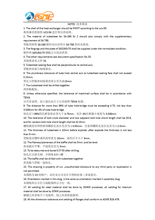
NOTES 技术要求1. The shell of the heat exchanger should be PWHT according to the ucs-56.换热器壳程按照UCS-56进行焊后热处理。
2. The material of tubesheet for SA-266 Gr 2 should also comply with the supplementary requirement of SA 788.管板用材料SA-266锻件还应该符合SA-788的补充要求。
3. The forgings and the plate of SA516Gr70 shall be supplied under the normalized condition.锻件和SA516Gr70钢板正火状态供货。
4. The other requirements see document specification No.33.其他要求见文件33.5. Tubesheet sealing face shall be perpendicular to central axis.管板密封面与轴线垂直。
6. The plumbness tolerance of tube hole central axis to tubesheet sealing face shall not exceed 0.15mm.管孔与管板密封面垂直度公差为0.15mm.7. Two tubesheet shall be drilled together.两管板配钻。
8. Unless otherwise specified, the tolerance of machined surface shall be in accordance with TEMA.出另有说明,加工面自由尺寸公差按照TEMA标准。
9. The distance for more than 96% of tube hole-bridge must be exceeding 4.75, not less than 3.048mm for 4% of tube hole-bridge.钻孔后≥96%的孔桥宽度必须大于4.75mm,允许4%孔桥最小宽度为3.048mm10. The tolerance of bolt circle diameter and two adjacent bolt hole chord length shall be ±0.6, and for random bolt hole chord length shall be ±2.0mm.螺栓圆直径和两相邻螺栓孔弦长允差为±0.63mm,任意两螺栓孔弦长允差为±2.0mm。
Section8-1-VIII-1-2007版ASME规范VIII-1修改汇总
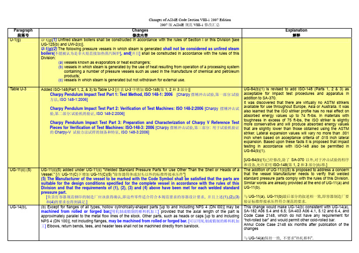
Paragraph 段落号Changes修改内容Explanation解释U-1(g) U-1(g)(1) Unfired steam boilers shall be constructed in accordance with the rules of Section I or this Division [see UG-125(b) and UW-2(c)].U-1(g)(2)The following pressure vessels in which steam is generated shall not be considered as unfired steamboilers[不能被认为是非火焰直接加热蒸汽锅炉], and[并且] shall be constructed in accordance with the rules of thisDivision:(a) vessels known as evaporators or heat exchangers;(b) vessels in which steam is generated by the use of heat resulting from operation of a processing systemcontaining a number of pressure vessels such as used in the manufacture of chemical and petroleumproducts;(c) vessels in which steam is generated but not withdrawn for external use.Table U-3 Added ISO-148(Part 1, 2, & 3) to Table U-3 [在表U-3中增加ISO-148(第1, 2和3部分)]Charpy Pendulum Impact Test Part 1: Test Method, ISO 148-1: 2006 [Charpy摆锤冲击试验,第一部分:试验方法, ISO 148-1:2006]Charpy Pendulum Impact Test Part 2: Verification of Test Machines: ISO 148-2:2006 [Charpy 摆锤冲击试验,第二部分:试验机的验证, ISO 148-2:2006]Charpy Pendulum Impact Test Part 3: Preparation and Characterization of Charpy V Reference TestPieces for Verification of Test Machines: ISO-148-3: 2006 [Charpy摆锤冲击试验,第三部分: 用于试验机验证的Charpy-V 试验方法试样的制备和特征, ISO 148-3:2006]UG-84(b)(1) is revised to add ISO-148 (Parts 1, 2 & 3) as acceptable for impact test procedures and apparatus in addition to SA-370.It was discovered that there are virtually no ASTM strikers available for use throughout Europe, Asia or Australia. It was also learned that the ISO striker profile has no real effect on absorbed energy values up to 74 ft-lbs. In materials with toughness in excess of 75 ft-lbs, the ISO striker is slightly more conservative and will produce absorbed energy values that are slightly lower than those obtained using the ASTM striker. Lateral expansion values will vary no more than .001 inch when based on acceptance criteria of .015 inch lateral expansion. Based upon these facts it is proposed that impact testing in accordance with ISO-148 also be permitted in UG-84(b)(1).[UG-84(b)(1)已经修改,除了SA-370以外,对于冲击试验的程序和设备,允许采用ISO-148(第1, 2和3部分)标准.]UG-11(c) (5) UG-11(c)(5) added under UG-11(c) “Welded Standard Pressure Parts for Use Other Than the Shell or Heads of a Vessel." [在UG-11(C)下增加UG-11(C)(5) ”除容器筒体或封头以外的标准焊接承压件”](5) The Manufacturer of the vessel to be marked with the Code Symbol shall be satisfied that the parts aresuitable for the design conditions specified for the complete vessel in accordance with the rules of thisDivision and that the requirements of (1), (2), (3) and (4) above have been met for each welded standardpressure part.[负责打容器规范钢印的制造厂应该获得确认,即这些零件适合符合本规范要求的容器设计要求, 并且上述(1),(2),(3)和(4)的要求也得到满足.] The addition of UG-11(c)(5) is proposed to address a concern that the vessel Manufacturer needs to verify that welded standard pressure parts comply with the rules of this Division. Similar words are already provided at the end of UG-11(a) and UG-11(b).与UG-11(a), UG-11(b)最后部分的叙述相一致,即容器制造厂要验证标准焊接承压件符合规范的要求.UG-14(b),(b) Except for flanges of all types, hollow cylindrically-shaped parts [up to and including NPS 4 (DN l00)] may be machined from rolled or forged bar,[用轧制或锻制的棒料机加工] provided that the axial length of the part isapproximately parallel to the metal flow lines of the stock. Other parts, such as heads or caps [up to and includingNPS 4 (DN 100)], not including flanges, may be machined from rolled or forged bar.[可以用轧制或锻制的棒料机加工]Elbows, return bends, tees, and header tees shall not be machined directly from barstock.This change would make UG-14(b) consistent with UG-14(a), SA-182 A06 5.4 and 6.5; SA-403 A06 4.1, 5.12 and 6.4, and Code Case 2148, which do not have any requirement for “hot-rolled bar” and would permit other cold-rolled bar.Annul Code Case 2148 six months after publication of the changes与UG-14(a)保持一致, 不要求”热轧棒料”.Paragraph 段落号Changes修改内容Explanation解释UG-35.2(d)UG-35.2(d)(1)Quick-actuating closures that are held in position by a locking mechanism designed for manual operation shall be designed such that if an attempt is made to open the closure when the vessel is underpressure, the closure will leak prior to full disengagement of the locking components and release of theclosure. The design of the closure and vessel shall be such that any leakage shall be directed away from thenormal position of the operator.(中文翻译略) It has been pointed out the paragraph UG-35.2(d)(1) can misinterpreted to require a closure to leak when the locking mechanisms are still fully engaged. This is not the intent of this paragraph. The paragraph is intended to make sure that if someone ties to open a closure which is under pressure that it will leak before the locking mechanism is fully disengaged and the closure is released. The re-wording clarifies this design requirement. In addition was pointed out that the designer of the closure may not know the location of the operator since he may not be the designer of the vessel or system. The re-wording clarifies this requirement没有技术上的修改,只是叙述更清楚.UG-36(b)(1)UG-36 Openings in Pressure Vessels…(b) Size of Openings(1) Properly reinforced openings in cylindrical and conical[锥型]shells are not limited as to size except with thefollowing provisions for design. The rules in UG-36 through UG-43 apply to openings not exceeding the following: forvessels 60 in. (1500 mm) inside diameter and less, one-half the vessel diameter, but not to exceed 20 in. (500 mm);for vessels over 60 in. (1500 mm) inside diameter, one-third the vessel diameter, but not to exceed 40 in. (1000 mm).(For conical shells, the inside diameter as used above is the cone diameter at the center of the opening) [(对于锥型筒体, 上述所指的内径是开孔中心处的锥体直径)]. For openings exceeding these limits, supplemental rules of1-7 shall be satisfied in addition to UG-36 through UG-43. Alternatively, openings in cylindrical or conical shellsexceeding these limits may be designed for internal pressure using the rules of 1-10 in lieu of those given in1-7(a) and / or 1-7(b).[作为另外一种方法,在圆筒体或锥形壳体上的超过这些限制的开孔也可以以内压按照附录1-10的规定来设计,而不必按照附录1-7(a) 和/或 1-7(b).]Added new appendix 1-10 for alternative method for design of large openings and revised UG-36(b)(1) to refer to it.Clarified that cones are also included in the reinforcement design rules in these sections. A note is also added to Appendix 1-7(b)(1) limiting application of the 1-7(b) rules to cones with a half apex angle not exceeding 30 degrees澄清了补强设计也适用于锥体. 在附录1-7(b)(1)中增加了一个注解以说明附录1-7(b)的规定仅适用于锥体半顶角不超过30度的情形.新增加了用于大开孔设计的另一方法附录1-10.UG-37UG-37(h) added under UG-37 REINFORCEMENT REQUIRED FOR OPENINGS IN SHELLS AND FORMED HEADS [新增UG-37(h)](h) The reinforcement rules in this Division are applicable for internal or external pressure and do notaddress the requirements for openings under the action of externally applied loadings (such as pipereactions). When externally applied loadings are to be considered, see U-2(g).[(h)本规范的规定适用于内压或外压,并没有规定适用于承受外部栽荷的开孔的要求(外部载荷指例如管子反作用力).如果考虑外部栽荷,参见U-2(g)] The reinforcement rules in Section VIII Division 1 are applicable for internal or external pressure and do not address the requirements for openings under the action of externally applied loadings (such as pipe reactions). This item was proposed because of several requests for interpretation that asked what opening reinforcement rules were applicable under loads other than pressure. This proposed action does not change any Code requirements, it merely provides information that may useful to the designer.澄清本规范的开孔补强规定适用于内压或外压,不适用于承受外部栽荷的情形.UG-37 Text in UG-37(a) revised:UG-37 REINFORCEMENT REQUIRED FOR OPENINGS IN SHELLS AND FORMED HEADS(a) Nomenclature. The symbols used in this paragraph are defined as follows:…The reinforcement rules of UG-37(a) are not clearly defined for the case of ERW or autogenously welded pipe or tube. The definition of “tr” in UG-37(a) implies that the seamless allowable stress values should be used in the calculation ofParagraph 段落号Changes 修改内容Explanation解释E = 1 (see definitions for t r and t r n)E 1 = 1 when an opening is in the solid plate or in a Category B butt joint; or= 0.85 when an opening is located in an ERW or autogenously welded pipe or tube. If the ERW or autogenously welded joint is clearly identifiable and it can be shown that the opening does not pass thru this weld joint, then E 1 may be determined as using the other rules of this paragraph; or[=0.85, 当一个开孔位于一个ERW 或自身焊接管时. 如果ERW 或自身焊接管接头清晰可见并且可以看到开孔并非通过该焊接接头时, 则E1可以以本段其它规则来确定,或]= joint efficiency obtained from Table UW-12 when any part of the opening passes through any other welded joint …the required thickness “tr”, even though the shell is constructed of ERW or autogenously welded pipe or tube. Past Interpretations VIII-1-92-25R and VIII-1-98-12 also support the use of seamless allowable stresses for the calculation of “tr” in ERW or autogenously welded pipe or tube.The proposed changes require that “E1” is taken as 0.85 for all shells constructed of ERW or autogenously welded pipe or tube, unless it can be shown that no part of the opening passes thru the ERW or autogenously welded joint. In the case where the ERW joint is readily identifiable and it can be shown that the opening does not pass thru the ERW weld joint, then “E1” may be determined using the other definitions of “E1” given in paragraph UG-37(a).新增要求.原来没有规定在计算tr 时,开孔位于ERW 或自身焊接管上时如何确定E1UG-42(a)(2), (c) & (e),UG-42 REINFORCEMENT OF MULTIPLE OPENINGSa) (See UG-39 for multiple openings in flat heads.) (a) When any two openings are spaced at less than two times their average diameter, so that their limits of reinforcement overlap [see Fig. UG-42 sketch (a)], the two openings shall be reinforced in the plane connecting the centers, in accordance with the rules of UG-37, UG-38, UG-40, and UG-41 with a combined reinforcement that has an area not less than the sum of the areas required for each opening. No portion of the cross section is to be considered as applying to more than one opening, nor to be considered more than once in a combined area(1) The available area of the head or shell between openings having an overlap area shall be proportioned between the two openings by the ratio of their diameters.(2) For cylinders and cones [对于圆筒和锥体] if the area of reinforcement between the two openings is less than 50% of the total required for the two openings, the supplemental rules of 1-7(a) and (c) shall be used. (3) A series of openings all……..c) Alternatively, any number of adjacent openings, in any arrangement, may be reinforced by using an assumed opening enclosing all such openings. The limits for reinforcement of the assumed opening shall be those given in UG-40(b)(1) and (c)(1). The nozzle walls of the actual openings shall not be considered to have reinforcing value. For cylinders and cones [对于圆筒和锥体] when the diameter of the assumed opening exceeds the limits in UG-36(b)(1), the supplemental rules of 1-7(a) and (c) shall also be used.e) When a series of two or more openings in a cylindrical or conical [或锥体] shell are arranged in a regular pattern, reinforcement of the openings may be provided per the rules of ligaments in UG-53. This item was established to make revisions to UG-36, UG-42 and Appendix 1-7 clarifying that cones are also included in the reinforcement design rules in these sections. A note is also added to Appendix 1-7(b)(1) limiting application of the 1-7(b) rules to cones with a half apex angle not exceeding 30 degrees澄清了补强设计也适用于锥体. 在附录1-7(b)(1)中增加了一个注解以说明附录1-7(b)的规定仅适用于锥体半顶角不超过30度的情形UG-84(a) &UG-84(b)(1). UG-84 CHARPY IMPACT TESTS UG-84(a) General. Charpy V-notch [V 型缺口] impact tests in accordance with the provisions of this paragraph shallbe made on weldments and all materials for shells, heads, nozzles and other vessel parts subject to stress due to pressure for which impact tests are required by the rules in Subsection C.UG-84(b)(1) Impact test procedures and apparatus shall conform to the applicable paragraphs of SA-370 or ISO-148 (Parts 1, 2 and 3) [或ISO-148 (第1, 2 和 3部分)] ISO-148 allows the usage of both Charpy V-notch and U-notch testing. Inclusion of ISO-148 into the code will require the words "V-notch" be added to UG-84(a) to ensure that Charpy V-notch testing is used exclusively.Include ISO-148 (Parts 1, 2 & 3) for CVN testing procedures & apparatus (ISO Striker). A recent incident has led to the discovery that the impact testing apparatus used throughoutParagraph 段落号Changes修改内容Explanation解释most of the industrial world (Europe, Asia & Australia) is not incompliance with SA-370/ASTM E23 because the Strikerprofile on the ISO machine has a different profile than theprofile designated by ASTM. Outside the USA mostcompanies and testing laboratories are using the ISO impacttesting apparatus in accordance with ISO-148 Therefore, anyimpact testing that is performed outside the USA cannot be instrict accordance with UG-84 as it is currently written. It wasdiscovered that there are virtually no ASTM strikers availablefor use throughout Europe, Asia or Australia. It was alsolearned that the ISO striker profile has no real effect onabsorbed energy values up to 74 ft-lbs. In materials withtoughness in excess of 75 ft-lbs, the ISO striker is slightlymore conservative and will produce absorbed energy valuesthat are slightly lower than those obtained using the ASTMstriker. Lateral expansion values will vary no more than .001inch when based on acceptance criteria of .015 inch lateralexpansion. Based upon these facts it is proposed that impacttesting in accordance with ISO-148 also be permitted inUG-84(b)(1).除了SA-370以外,对于冲击试验的程序和设备,允许采用ISO-148(第1, 2和3部分)标准.但因为ISO-148还包括了U型缺口的冲击试验,所以在UG-84要规定V型缺口.UG-90(b)(19) UG-90 GENERAL(b) The Manufacturer has the responsibility of assuring that the quality control, the detailed examinations, and thetests required by this Division are performed. The Manufacturer shall perform his specified duties. See UG-92 and10-15. Some, but not all, of these responsibilities, which are defined in the applicable rules, are summarized asfollows:…(19) providing for retention of radiographs (UW-51), ultrasonic test reports (12-4), and Manufacturer’s DataReports (UG-120),and other documents as required by this Division (10-13). [和本规范附录10-13规定的其它文件]Revise Appendix 10-13 to require the retention of pertinent records by the Manufacturer for at least three years after signing of the Manufacturers Data Report.附录10-13作了修改, 要求部分有关的记录必须在”制造厂数据报告”签发以后至少保留三年.UG-117(f); UG-117 CERTIFICATES OF AUTHORIZATION AND CODE SYMBOL STAMPSUG-117(f) Evaluation for Authorization and Reauthorization. Before issuance or triennial renewal of a Certificate ofAuthorization for use of the U or UM Stamp, the Manufacturer’s facilities and organization are subject to a joint reviewby a representative of his inspection agency and an individual certified as an ASME Designee who is selected by theconcerned legal jurisdiction. A written description or checklist of the Quality Control System which identifies whatdocuments and what procedures the Manufacturer will use to produce a Code item shall be available for review.A written report to the Society shall be made jointly by the ASME Designee and the Inspection Agency employed bythe Manufacturer to do his Code inspection. This report is then reviewed by the Subcommittee on Boiler and PressureVessel Accreditation, which will either issue a Certificate of Authorization or notify the applicant of deficienciesrevealed by the review. In such a case, the applicant will be given an opportunity to explain or correct thesedeficiencies. The changes allow the Manufacturers to be audited more comprehensively.Revise UG-117(f) to make the retained records available to the Authorized Inspector (AI) supervisors or Review Teams for the purpose of performing reviews for the issue or renewal of Certificates of Authorization.该修改允许制造厂能够得到更全面的审查,在取证或换证审查中,相关的记录要提供给AIS或审核组审查.Paragraph 段落号Changes 修改内容Explanation解释Certificates of Authorization will be endorsed to indicate the scope of activity authorized. Authorization may include field operations if the review team determines that these operations are adequately described in the quality control manual, and this determination is accepted by the Society.Before issuance or renewal of a Certificate of Authorization for use of the UV or UD Stamp, the valve or rupture disk device Manufacturer’s or Assembler’s facilities and organization are subject to a review by a representative from an ASME designated organization. A written description or checklist of the quality control system, which identifies the documents and procedures the Manufacturer or Assembler will use to produce Code pressure relief valves, shall be available for review. The representative from an ASME designated organization shall make a written report to the Society, where the Subcommittee on Boiler and Pressure Vessel Accreditation will act on it as described above.The purpose of the review is to evaluate the applicant’s Quality Control System and its implementation. The applicant shall demonstrate sufficient administrative and fabrication functions of the system to show that he has the knowledge and ability to produce the Code items covered by his Quality Control System. Fabrication functions may be demonstrated using current work, a mockup, or a combination of the two. Additionally, retained records as required by this division and the Quality Control System, shall be made available to the Authorized Inspector Supervisors or the review teams designated by the ASME. [另外, 本规范和质量控制体系要求的保存的记录必须提供给主任授权检验师或ASME 指定的审核组审查.] UG-116(e) &UG-116(e)(1) UG-116 REQUIRED MARKING (e) When radiographic or ultrasonic examination has been performed on a vessel [当射线或超声波探伤已经运用于一台容器上时] in accordance with UW-11, marking shall be applied under the Code Symbol as follows:(1) “RT 1” when all pressure-retaining butt welds, other than Category B and C butt welds associated with nozzles and communicating chambers that neither exceed NPS 10 (DN 250) nor 11⁄8 in. (29 mm) wall thickness [except as required by UHT-57(a)], satisfy the full radiography requirements of UW-11(a) for their full length [在全部长度上满足UW-11(a)全部射线探伤的要求]; full radiography of the above exempted Category B and C butt welds, if performed, may be recorded on the Manufacturer’s Data Report; orNameplate markings as listed in UG-116(e) are currently only applicable if the vessel has been radiographed and UG-116(e)(1) states that the marking “RT1” can only be used if the welded joints have been radiographed over their entire length. UG-116(e)(2), UG-116(e)(3), and UG-116(e)(4) state that the markings “RT2”, “RT3”, and “RT4” must be used on a vessel if the radiographic requirements have been met for their respective markings even when ultrasonic examination has been used for the closure seam per UW-11(a)(7). Code Case 2235-6 allows ultrasonic examination of other welded joints other than the closure seam in lieu of radiographic examination provided specific additional criteria are met. This change will allow the vessels to be stamped with “RT-1”, “RT-2”, and RT-3” when the requirements of radiography have been met without specifically requiring a vessel to be radiographed. The specific reference to UW-51 (Radiographic and Radioscopic Examination of Welded Joints) will be deleted in the event of ultrasonic examination. The requirements in the replies are currently required under Code Case 2235-6(k) and (l).原来的关于铭牌上”RT1”, “RT2”, “RT3”或”RT4”仅适用于焊缝做相应射线探伤的情形. 规范案例2235-6允许对除闭口焊缝以外的其它焊缝做超声波探伤以代替射线探伤,只要特定的附加标准要求得到满足. 此改变允许当射线探伤的要求得到满足而没有特殊要求进行射线探伤时,容器打上”RT1”, “RT2”和”RT3”的标Paragraph 段落号Changes修改内容Explanation解释记.UG-120(a) UG-120 DATA REPORTS(a)A Data Report shall be filled out on Form U-1 or Form U-1A by the Manufacturer and shall be signed by theManufacturer and the Inspector for each pressure vessel marked with the Code U Symbol.(1)Same day production of vessels may be reported on a single Form provided all of the following requirementsare met:(a)vessels must be identical;(b)vessels must be manufactured for stock or for the same user or his designated agent;(c)serial numbers must be in uninterrupted sequence; and the Manufacturer’s written Quality ControlSystem includes procedures to control the development, distribution, and retention of the Data Reports.(2)The number of lines on the Data Report used to describe multiple components (e.g., nozzles, shell courses)may be increased or decreased as necessary to provide space to describe each component. If addition of lines usedto describe multiple components results in the Data Report exceeding one page, space must be provided for theManufacturer and Authorized Inspector to initial and date each of the additional pages. Horizontal spacing forinformation on each line may be altered as necessary. All information must be addressed; however, footnotesdescribed in the remarks block are acceptable, e.g., for multiple cases of “none” or “not applicable.(3)The Manufacturer shall [制造厂必须]:(a)furnish a copy of the Manufacturer's Data Report to the user and, upon request to the Inspector;[提供一份制造厂数据报告给用户, 如要求给授权检验师;](b)submit a copy of the Manufacturer's Data to the appropriate enforcement authority in thejurisdiction in which the vessel is to be installed where required by law;[如法规要求, 递交一份制造厂数据报告给容器安装地的主管当局的有关机构](c)keep a copy of the Manufacturer's Data Report in a safe repository for at least 3 years. In lieu of(b) above, the vessel may be registered and the Data Reports filed with the National Board ofBoiler and Pressure Vessel Inspectors, 1055 Crupper Ave., Columbus, Ohio 43229.[在一个安全的地方保存一份制造厂数据报告至少三年. 作为代替上述(b), 容器可以到美国锅炉和压力容器检验师总部注册,数据报告到该处备案.](4) A Manufacturer’s Certificate of Compliance on Form U-3 shall be completed and signed by the Manufacturerfor each pressure vessel marked with the Code UM Symbol. This Certificate shall be maintained by the Manufacturerfor 5 years and a copy made available upon request. Identical vessels up to 1 day’s production may be recorded on asingle Certificate of Compliance.The changes allow the Manufacturers to be audited more comprehensively.Revise Appendix 10-13 to require the retention of pertinent records by the Manufacturer for at least three years after the signing of the Manufacturers Data Report.该修改允许制造厂能够得到更全面的审查,在取证或换证审查中,相关的记录要提供给AIS或审核组审查.UG-134 UG-134 PRESSURE SETTING AND PERFORMANCE REQUIREMENTS [压力设定和性能要求](f) Pressure relief valves shall be designed and constructed, such that when installed per UG-135, the valves willoperate without chattering and shall not flutter at the flow-rated pressure in a way that either would interfere with themeasurement of capacity or would result in damage(中文翻译略)UG-136(c)(3) UG-136 MINIMUM REQUIREMENTS FOR PRESSURE RELIEF VALVESUG-136(c)(3) A Manufacturer or Assembler may be granted permission to apply the UV Code Symbol to productionpressure relief valves capacity certified in accordance with UG-131 provided the following tests are successfullycompleted. This permission shall expire on the fifth anniversary of the date it is initially granted. The permission maybe extended for 5 year periods if the following tests are successfully repeated within the 6-month period beforeexpiration.Paragraph 段落号Changes修改内容Explanation解释Two sample production pressure relief valves of a size and capacity within the capability of an ASME acceptedlaboratory shall be selected by a representative from an ASME designated organization. Pressure relief valveshaving adjustable blowdown construction shall have the control elements positioned by the Manufacturer orAssembler for a blowdown typical of production methodsOperational and capacity tests shall be conducted in the presence of a representative from an ASME designatedorganization at an ASME accepted laboratory. The pressure relief valve Manufacturer or Assembler shall be notifiedof the time of the test and may have representatives present to witness the test. If a pressure relief valve withadjustable blowdown construction selected from a Manufacturer exhibits a blowdown that exceeds7% of theset pressure or 3 psi (20 kPa), whichever is greater, during operational and capacity tests, then an adjustmentshall be made to meet this performance condition and the operational and capacity tests shall be repeated.This adjustment may be made on the flow test facility.Should any pressure relief valve fail to relieve at or above its certified capacity or should it fail to meetperformance requirements of this Division, the test shall be repeated at the rate of two replacement pressure reliefvalves, selected in accordance with (c)(3)(a) above, for each pressure relief valve that failed.Failure of any of the replacement pressure relief valves to meet the capacity or the performance requirements inUG-134 of this Division shall be cause for revocation within 60 days of the authorization to use the Code Symbol onthat particular type of pressure relief valve. During this period, the Manufacturer or Assembler shall demonstrate thecause of such deficiency and the action taken to guard against future occurrence, and the requirements of (c)(3)above shall apply.…(中文翻译略)UG-136(d)(2), UG-136(d)(3) UG-136 MINIMUM REQUIREMENTS FOR PRESSURE RELIEF VALVESUG-136(d) Production Testing by Manufacturers and AssemblersUG-136(d)(2) Hydrostatic Pressure Tes t(a)The pressure containing parts of each valve shall be hydrostatically tested at a pressure at least 1.5 times the design pressure of the parts. Parts meeting the following criteria shall be exempt from hydrostatic testing:(1)the applied stress under hydrostatic test conditions does not exceed 50% of the allowable stress: and(2)the part is not cast or welded.(b)Testing may be performed pneumatically at a pressure of 1.25 times the design pressure of the part. Pneumatic testing can be hazardous; it is therefore recommended that special precautions be taken when conducting a pneumatic test(c)Testing may be done in the component or assembled condition.(d)When the valve is designed for discharging directly to atmosphere, the valve components downstream of the valve disk are exempt from hydrostatic testing.(e)Valve components downstream of the disk and fully contained within the body are exempt from hydrostatic testing(f)These tests shall be conducted after all machining and welding operations on the parts have been completed(g)There shall be no visible sign of leakageUG-136(d)(3) The secondary pressure zone of each closed bonnet pressure relief valve exceeding NPS 1 (DN 25) inlet size when such pressure relief valves are designed for discharge to a closed system shall be tested with air orParagraph 段落号 Changes 修改内容Explanation解释other gas at a pressure of at least 30 psi (200 kPa). There shall be no visible sign of leakage. (see footnote 62)Footnote 62The User may specify a higher test pressure commensurate with the back pressure anticipated in service.(中文翻译略)UG-137(d)(2)UG-137 MINIMUM REQUIREMENTS FOR RUPTURE DISK DEVICES UG-137(d) Production Testing by Manufacturers UG-137(d)(2) Hydrostatic Pressure Tes t(a)The pressure containing parts of each rupture disk holder shall be hydrostatically tested at a pressure at least 1.5 times the design pressure of the parts. Holders meeting the following criteria shall be exempt from hydrostatic testing:(1)the applied stress under hydrostatic test conditions does not exceed 50% of the allowable stress; and(2)the holder is not cast or welded(b)Testing may be performed pneumatically at a pressure of 1.25 times the design pressure of the part. Pneumatic testing can be hazardous; it is therefore recommended that special precautions be taken when conducting a pneumatic test.(c)Testing may be done in the component or assembled condition.(d)When the outlet of the device is not designed to contain pressure, holder components downstream of the rupture disk are exempt from hydrostatic testing.(e)Holder components downstream of the rupture disk and fully contained within the holder are exempt from hydrostatic testing.(f)These tests shall be conducted after all machining and welding operations on the parts have been completed.(g)There shall be no visible sign of leakage(中文翻译略)Fig. UG-84.1 and Fig.UG-84.1M Under GENERAL NOTES (c), added See UCS-66(g) in the end. 在总的注解(C)下,最后增加”见UCS-66(g)”When a 5F (3C) tolerance was added to paragraphs UCS-66(g) for materials that are required to be impact tested by the material specification, no such tolerance was explicitly added to the Notes in the Figures referenced from those paragraphs. This editorial revision removes this apparent discrepancy and just references the Code paragraphs for the rules.编辑上的修改以消除前后文的明显矛盾.,UW-13(b)(1)UW-13 ATTACHMENT DETAILSUW-13(b)(1) Ellipsoidal, torispherical, and other types of formed heads, shall be attached to the shell with a butt weld or [以对接焊缝, 或] as illustrated in the applicable Fig. UW-13.1 sketches (a), (b), (c), (e), and (k). The construction shown in sketch (f) may also be used for end heads when the thickness of the shell section of the vessel does not exceed 5⁄8 in. (16 mm) [see also (c) below]. Limitations relative to the use of these attachments shall be as given in the sketches and related notes and in Table UW-12. Figure UW-13.1 sketches (g), (h), and (j) are examples of attachment methods which are not permissible.Fig. UW-13.1 sketch (d) illustrates the required details for the attachment of heads to shells with a butt weld. It is composed of two sketches; the right side sketch shows when a tapered transition per UW-13(b)(3) is required and the left side sketch shows when such a transition is not required.。
ASME规范标准学习重点
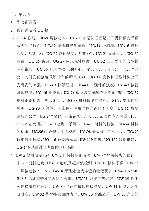
一、第八卷1、引言都要看。
2、设计需要看UG篇3、UG-4总则、UG-9焊接材料、UG-11有无认证标记工厂提供预测或预成型的受压件、UG-12螺栓和双头螺栓、UG-14杆和棒、UG-16设计总则,尤其(e)、UG-20设计温度,尤其(f)、UG-21设计压力、UG-22载荷、UG-25腐蚀、UG-27内压壳体厚度、UG-32凹面受压的成型封头和锥段、UG-36压力容器上的开孔,尤其(b)开孔尺寸、(c)“已完工的开孔的强度及设计”的所属(3)、UG-37壳体和成型封头上开孔所需的补强、UG-40补强范围、UG-41补强件的强度、UG-45接管颈部厚度、UG-46检查孔、UG-76板材及其他库存材料的切割、UG-77材料识别标志(见UG-25)、UG-78材料缺陷的修补、UG-79受压件的成型、UG-80圆筒体、圆锥体和球形壳体允许的不圆度、UG-81成型封头的公差、UG-84“夏比”冲击试验,尤其(b)试验程序的所属(1)、UG-85热处理、UG-90总则(了解)、UG-93材料的检验、UG-94材料的标志、UG-96组合键尺寸的校核、UG-98最大许用工作压力、UG-99标准液压试验、UG-116必要的标志、UG-119铭牌、UG-120数据报告、UG-140系统设计考虑的超压保护4、UW-2使用限制(a)、UW-3焊接接头的分类、UW-9“焊接接头的设计”中(c)削斜过渡、UW-11射线及超声波检测、UW-12接头系数、UW-15“焊接连接’中(b)、UW-16开孔处链接焊缝的最低要求、UW-21 ASME B16.5承插和带颈平焊法兰焊缝、UW-28焊接工艺评定、UW-29焊工和焊接操作的评定、UW-30允许的最低焊接温度、UW-31切割、装配及对准、UW-32待焊接表面的清理、UW-33对准公差、UW-35完工的纵、环向焊接接头、UW-37其他焊接要求、UW-40“焊后热处理工艺“,尤其(c)(f)、UW-51焊接接头的射线检测、UW-52焊接接头的抽样检测、UW-54无损检测人员的资格评定5、UCS-10螺栓材料、UCS-11螺母和垫圈、UCS-23最大许用应力值、UCS-56焊后热处理要求、UCS-57射线检测、UCS-66材料、UCS-79受压件成型二、PP规范(ASME B31.1)1、102.3.2持续载荷和二次应力的极限值、102.3.3由偶然荷载产生的计算应力极限值102.4裕量、103管道元件的压力设计准则、104元件的压力设计、105.2.1铁基管、111.2对接焊缝、111.4角焊缝、122.1.3给水管道、123.1.1表列材料、123.1.2蒸汽管道、123.1.6材料或成品的标志、123.2.2锅炉外部管道、124.1.1灰口铸铁、124.1.2、126.1球墨铸铁、127.4.8焊制支管接头、Table132焊后热处理、136.3.2无损检测人员的资格评定、136.4焊缝的检查方法、137压力试验、2、第二卷SA20、SA105、SA106、SA450、SA530、SA516、SA961、3、C篇SFA5.1、SFA5.184、D篇表1A5、第五卷第一章T150通篇看。
ASME Code Section VIII-1(Aug 2007)
ASME锅炉压力容器规范第八卷第一分篇 简介
9焊接工艺评定 9焊工技能评定 9焊前接头检查 9尺寸和表面检查 9热处理 9无损探伤及文件保管 9压力试验 9钢印标记 9签发数据报告和让AI签署 9数据报告的保存
职责…
ASME锅炉压力容器规范第八卷第一分篇 简介
¾AI的职责:
9确认制造厂的资格和体系运转 9确认设计计算 9确认焊接工艺评定 9确认焊工资格 9确认材料符合规范 9确认热处理工序
单位转换的结果必须保留至少三个有效数字.
11
适用范围…
ASME锅炉压力容器规范第八卷第一分篇 简介
9 使用上述规定的精确单位转换必须保证尺寸的一贯性.公英制单 位之间转换的系数可参见非强制性附录”ASME锅炉和压力容 器规范公英制单位使用指南”.当使用当地单位制时,制造厂必须 提供转换系数的来源,AI或CI要对该来源进行验证和认可.
铭牌的粘接 电加热或燃气夹套蒸汽釜 由板材机加工的管板和平盖的颈部 加工硬化的镍材建造的带夹套的容器 整体锻造容器 铜,铜合金和钛合金整体翅片无缝冷凝管和换热管的外 压设计 卡箍连接件的设计规则 泄压阀排量鉴定的测试试验室和授权观察员的认可 压力容器和换热器膨胀节 搪玻璃容器的另一要求 空冷换热器管箱的另一种角接焊接接头详图 型槽绕带多层压力容器特殊截面钢带的要求(04已删除) 不穿透容器壁的钻孔规则 带附加要求的Cr-Mo钢的焊接和热处理规则 圆筒及壳体球面部分的局部减薄区域 公式中使用的标准单位 压力容器用高硅含量不锈钢的使用要求
9 制造厂A完成待组装的部件,并打U部件钢印和完成U-2或U2A表. 制造厂B完成现场组装及所需的探伤,压力试验.并打U 钢印和完成U-1或U-1A表;
9 制造厂A完成待组装的部件.制造厂B完成现场组装,并完成 U-2或U-2A表.制造厂A打U钢印和完成U-1或U-1A表.
ASMECodeSectionVIII1UM共71页
✓ 附录H
应对爆燃产生的载荷的指南
✓ 附录K
焊接接头的剖面检验
✓ 附录L
规范公式和规则的应用举例
✓ 附录M
安装和操作
✓ 附录P
确定许用应力值的基准
✓ 附录R
预热
✓ 附录S
对螺栓法兰连接件设计的考虑事项
❖规范的结构
ASME锅炉压力容器规范第八卷第一分篇 简介
➢非强制性附录
✓ 附录T ✓ 附录W
温度防护 编写制造厂数据报告的指南
表
强制性附录
非强制性附录
索引
❖规范的结构…
ASME锅炉压力容器规范第八卷第一分篇 简介
➢A分卷-通用要求
✓UG篇-所有建造方法和所有材料的通用要求
▪ UG-1 范围 ▪ UG-4~UG-15 材料 ▪ UG-16~UG-35 设计 ▪ UG-36~UG46 开孔和补强 ▪ UG-75~UG-85 制造 ▪ UG-90~UG-103 检验和试验 ▪ UG-115~UG-120 标记和报告
➢ ASME VIII-1的范围 [U-1(c)(2)]
下列分类的容器不在ASME VIII-1的范围之内:
✓ 其它ASME规范各卷的设备 ✓ 火管加热器 ✓ 泵,压缩机,发动机等的受压部件 ✓ 管道系统 ✓ 管路部件或附件 ✓ 盛水容器、设计压力≤2MPa,并且设计温度≤99c ✓ 不超过一定条件的蒸汽加热的热水储罐 ✓ 内压或外压不超过100KPa的容器(尺寸不限) ✓ 载人压力容器
✓ 附录Y
在螺栓圆外金属对金属相接触的平面法兰
✓ 附录DD
授权证书上内容的阅读指南
✓ 附录EE ✓ 附录FF ✓ 附录GG
半管式夹套
快开(快启动)的端盖的设计及操作指南
ASME锅炉及压力容器规范国际性规范 Ⅷ 第1册 压力容器建造规则(2006增补)

ASME锅炉及压力容器规范国际性规范VIII第一册压力容器建造规则2006增补ASME锅炉及压力容器委员会压力容器分委员会编著中国《ASME规范产品》协作网(CACI)翻译、发送2007 年5 月2006增补发送说明经美国机械工程师学会(ASME)许可,中国《ASME规范产品》协作网(CACI)翻译出版了2004版ASME锅炉及压力容器规范和相关规范。
与规范英文原版一样,我们也翻译有关增补。
为方便更换,英文原版是活页的,所以其增补也是活页的。
而规范中译本是装订本,因此我们以勘误表方式翻译、编辑了增补,即注明04版中文本页码、章节、修改部位和增补的修改内容。
如修改内容多或有新增和变动较大的图、表,在勘误表中放不下的,则将修改内容及图、表,放在勘误表后面,并注明位于中译本中的页码。
05增补已在2006年5月发送,现将06增补发给用户。
本增补由CACI聘请丁伯民翻译引言(Ui-U3), UG-1~Ug-55, UHX, 附录1~3,9, 13~14,19~29,30,32,33,A,C,D,E,G,H,L,M,P,S,T,Y,EE,FF,GG邵国华校对;王国平翻译、UG-75~UG-137, Subsection B, Subsection C (除UHX外),附录 4~8,10~12,16~18,31,F,K,R,W,DD,陈登丰校对,CACI编辑、发送。
中文版增补版权属CACI所有。
本增补原版在2006年7月1日发布,自发布之日起6个月后生效。
执行时应以英文原版为准。
由于各种原因,本次翻译发送的增补可能会有不足和错误,希望广大用户和读者批评和指正,以便改进。
来信请寄:北京市西城区月坛南街26号中国《ASME规范产品》协作网邮政编码:100825电子邮箱:caci@中国《ASME规范产品》协作网2007年5月2006年度增补04中文版页码章节修改部位 06增补修改内容xxii 目录 UHA-109修改为:“885℉(475℃)脆化”xxix 目录强制性附录在附录33下增加:附录34 压力容器用高硅钢的使用要求……………………(440.1)xxix 目录非强制性附录在附录GG下增加:附录HH 换热管胀接工艺及评定 (556)(参见05增补)xxxii 前言最后四段删除xxxiv 成员名单(略)2 引言 U-1(c)(2)(h)全文修改为:(h)容器在其顶部的设计压力(见3.2)不超过以下限制者,其尺寸不限[见UG-28(f), 9-1(c)]:(1)容器的内压或外压不超过15psi(100kPa);(2)组合单元在每一受压室的内压或外压不超过15psi(100kPa),且在公用元件上的压差不超过15psi(100kPa)[见 UG-19(a)].4 引言 U-4全文修改为:U-4 计量单位不管是美国习惯单位,SI单位或地方性习惯单位都可以采用以表明与本版的所有要求,例如材料,设计,制造,检验,检测,试验,认证和超压防护等相符。
ASME压力容器焊后热处理程序
ASME压力容器焊后热处理程序Postweld Heat Treatment Procedure1. General总则This procedure is supplemented to the “Heat Treatment Instruction ”(specific heat treatment instruct ion), and is applicable to the boilers and pressure vessels and parts of carbon steels (PNo1 Gr.Nos 1, 2&3) fabricated according to the latest ASME Code Sect Ⅰ,B31.1and VIII Div.1.本程序是对”热处理工艺卡”(专用热处理工艺)的补充,用于按ASME规范第Ⅰ卷,B31.1和第Ⅷ卷第1分册的要求,碳钢(PNO组1、2或3)所制造的锅炉/压力容器和部件; For the other materials, the applicable procedure and condition will be added or provided. 对于其它材料,将增加或提出相应程序或条件;2. Personnel人员The PWHT operator shall be familiar with the general requirements of heat treatment and has been properly trained.焊后热处理操作者应熟悉热处理的一般要求并经过适当的培训;3.Equipment设备According to the specific situation根据具体情况编制4. Procedures工艺One of the following procedures may be used for the PWHT:焊后热处理应按下列工艺之一执行;4.1 If it is practicable, the vessel shall be heated as a whole in an enclosed furnace. 如可行,整台容器装入封闭炉内加热;4.2Heating the vessel in more than one heat in furnace, provided the overlap of the heated sections of the vessels at least 5 ft. When this procedure is used, the portion outside of the furnace shall be sh ielded so that the temperature gradient is not harmful.容器在一加热炉内分几段加热,要求被重复加热的各段至少有5英尺长(1.5m),当采用这种工艺时, 在炉外的部分应予以覆盖保温,以免产生有害的温度梯度;4.3.Heat of the shell sections and/or portions of the vessels to postweld heat treat longitudinal joints or complicated welded details before joining to make the completed vessels. When the vessel is req uired to be PWHT, and it is not practicable to PWHT the completed vessel as a whole or in two or more heats as provided in 4.2 above, any circumferential joints not previously PWHT may be therea fter locally PWHT by heating such joins by any appropriate means that will assure required uniform ity. As a minimum, the soak band shall contain the weld, heat affected zone, and a portion of base m etal adjacent to the weld being heat treated. The minimum width of this volume is the widest width of weld plus T or 2in(51mm), whichever is less, on each side or end of the weld. The portion outsid e the heating device shall be protected so that the temperature gradient is not harmful. This procedur e may also be used to PWHT portions of new vessels after repairs.在组装成整体容器之前,可对筒节或容器的的纵焊缝或结构复杂的焊接点进行焊后热处理.对要求焊后热处理,但有不能整体热处理,或如 4.2条所述分两次或多次热处理,其上任何未经焊后热处理的环焊缝,可采用任何能达到保证均匀要求的加热方法进行局部热处理.此时加热应包括焊缝热影响区及临近的母材,其宽度应为焊缝最大宽度处的每侧各加T或2英寸(51mm)两者之中最小者. 加热装置以外的部分应予以覆盖保温,以免产生有害的温度梯度.该工艺还可用于新容器返修后各部分的焊后热处理;4.4 Heating the vessel internally by any appropriate means and with adequate indicating and recordi ng temperature devices to aid in the control and maintenance of a uniform distribution of temperatur e in the vessel wall. Previous to this operation, the vessel should be fully enclosed with insulating m aterial, or the permanent insulation may be installed provided it is suitable for the required temperat ure. In this procedure the internal pressure should be kept as low as practicable, but shall not exceed 50% of the maximum allowable working pressure at the highest metal temperature expected during the PWHT period.采用任何适当方法在容器内部加热并用足够的温度指示记录仪表,协助控制并维持容器器壁温度的均匀分布,在进行本操作之前容器应用绝热材料包起来,或设置永久性绝热材料,以适应所要求的温度.在此过程中容器的内压应保持愈低愈好,不应超过焊后热处理期间预期的最高金属壁温下的最大许用工作压力的50%;4.5 Heating a circumferential band containing nozzles or other welded attachments that required P WHT in such a manner that the entire band shall be brought up uniformly to the required temperatur e and held for the specified time. The circumferential band shall extend around the entire vessel, sha ll include the nozzle or welded attachment. As a minimum, the soak band shall contain the weld, he at affected zone, and portion of base metal adjacent to the weld being heat treatment. The minimum width of this volume is the widest width of weld plus T or 2in(51mm), whichever is less, on each si de or end of the weld. The portion of the vessel outside of the circumferential band shall be protect ed so that the temperature gradient is not harmful.接管或其它焊接附件要求焊后热处理时,可对其所在环带加热,要求整个环向包括接管或焊接附件均应包容在内,其宽度应为焊缝最大宽度处的每侧各加t或2英寸(51mm),两者之中最小者.环带以外的部分应予以覆盖保温,以免产生有害的温度梯度;4.6 Heating a circumferential joints of the pipe or tubing by any appropriate means using a soak band that extends around the entire circumference. The minimum width of this volume is the widest wi dth of weld plus T or 2in(51mm), whichever is less, on each side or end of the weld. The portion of the soak band shall be protected so that the temperature gradient is not harmful.采用任一适的方法加热管子的环缝,加热带环绕整个圆周布置.加热带以外的部分应予以覆盖保温,以免产生有害的温度梯度;5.Operation操作The operator shall perform the PWHT in accordance with those requirement as specified following: 操作者应按下面指定的这些要求完成焊后热处理:5.1The temperature of the furnace shall not exceed 800℉at the time the Vessel or the partis placed in it.容器或零件进炉时,炉温不得超过800℉;5.2 Above 800℉(427℃),the rate of heating shall be not more than 400.℉/hr divided by the maximum metal thickness of the shell or head plate in inches, but in no case more than400℉/hr. During the heating period there shall not be a greater variation in temperature throughout the portio n of the vessel being heated than 250℉ within any 15 feet interval of length.800℉(427℃)以上时,加热速率不得大于400℉/hr除以壳体或封头的最大板厚(单位:英寸),但决不能超过400℉/hr,升温期间,被加热容器的各个部分不应有较大的温度差异,在15英寸(4.5米)长的范围内的温度差异不得大于250℉(139℃);5.3 The vessel or vessel part constructed of materials which belong to P-No1GrNos1,2,3 shall be he ld at or above the temperature specified in Table 1or 2 for the period of time specified in the Table. 用PNo1GrNos1,2,3建造的容器或零部件,应在等于或大于表1或表2中所规定的温度下保持表中所规定的时间;TABLE 1表1 PWHT REQUIREMENTS FOR CARBON AND LOW ALLOY STEELSTABLE 2表2ALTERNATIVE PWHT REQUIREMENTS FOR CARBON AND LOW ALLOY STEELSs greater than 1 inch.注1. 此为厚度小于等于1英寸时的最少保温时间,当厚度大于1英寸后,厚度每增加1英寸最少保温时间应增加15分钟;(2) These lower PWHT temperature permitted only for P-No.1 Gr.Nos.1 and 2materials. During the holding perio d, there shall not be a difference greater than 150℉(83℃) between the highest and lowest temperature throughout the portion of the vessel being heated, except wher e the range of further limited by the “Heat Treatment Instruction Card”.注2. 这些较低的焊后热处理温度仅适用于PNo组1和组2的材料.除“热处理工艺卡”中进一步限制的范围外,在保温时间内,被加热容器的各部分的最高温度差不得大于150℉(83℃);5.4 During the heating and holding period, the furnace atmosphere shall be so controlled as to avoid excessive oxidation of the surface of the vessel. The furnace shall be of such design as to prevent di rect impingement of the flame on the vessel.在加热和保温期间应控制炉内气氛,以免容器表面过度氧化,设计炉膛时应防止火焰直接喷烧容器;5.5Above 800℉,cooling shall be done in a closed furnace at a rate not greater than 500℉/hr, divided by the maximum metal thickness of the shell or the head plate in inches, but in no case more than 500℉/hr. From 800℉ the vessel may be cooled in still air.The rates of heating and cooling need not be less than 100℉/hr. In all cases considerationof closed chamber and complex structure may indicated reduced rates of heating and cooling to avoi d structural damage due to excessive thermal gradients.温度高于800℉(427℃)时降温应在封闭的炉内或冷却室内进行,其冷却速率不得大于500℉/hr(278℃/hr)除以壳体或封头的最大金属板厚(单位:英寸),但决不能超过500℉/hr,温度低于800℉后容器可在空气中冷却.加热和冷却速率均不得低于100℉/hr(56℃/hr),考虑到炉膛和复杂的结构,有必要减少加热和冷却速度以防由于过热而造成的结构损坏;5.6 The temperature recorder and thermocouples shall be in the effective calibration period. The the rmocouples shall directly touch the vessel at the bottom, center and the top of the charge, or in oth er zones of possible temperature variation so that the temperature indicated shall be true temperatur e for all vessels or parts in those zones.温度记录仪和电偶应在有效检定期内,热电偶应在炉的底、中、顶部接触容器或温度可能变化的其它区域,这样指示的瓦温度才是整个容器或那些区域的零件的真实温度;5.7The thermocouple should be fastened to the attachment plate (with thread hole) by bolts. The att achment plate should be welded to workpiece. The welding shall be performed using the qualified WPS by the qualified welder.热电偶应用螺柱固定在工件上,带有螺纹孔的连接板焊在工件上,焊接由有资格的焊工用评定的WPS完成;5.8 The Heat Treatment Engineer shall be indicated identification number of the heat treated items, heat treatment requirements and furnace name including No. & recorder No. on the Heat Treatment Record attached to the time---temperature chart.热处理工程师应在热处理记录上指明被热处理件的识别号、热处理要求、炉名以及热电偶号和记录仪号,并附在时间—温度曲线上;5.9Examination Engineer shall supervise the heat treatment operation and review the time---temper ature chart and the Heat Treatment Record to verify conformance to the procedure.检查工程师应监督热处理工作并审核时间—温度曲线图和热处理记录以认定其与工艺的一致性;6 Examination检查6.1 PWHT shall be done before the hydrostatic test and after any welded repairs except as permitted by the code.热处理应在水压之前以及焊接修补之后进行,范围允许者除外;6.2 The examiner shall collect the Heat Treatment Record and time —temperature chart. 检查员应收集热处理记录和时间—温度曲线图;6.3 The Chief Examination Engineer shall review all records related to the heat treatment to verify t hat conditions of heat treatment meet the requirements of the procedure, the customer’s specificatio n, certificates of materials and applicable WPS.检查责任工程师应审核有关热处理的所有记录并认定热处理条件满足工艺、用户技术条件、材料证明书和所使用的WPS的要求;。
ASME_VIII-1培训教材

• UNF篇
非铁金属建造压力容器的要求(有色金属)
• UHA篇
高合金钢建造压力容器的要求(包括不锈钢)
• UCI篇 铸铁建造压力容器的要求
• UCL篇 整体复合耐腐蚀层,堆焊覆层或衬里材料
❖规范的结构…
• UCD篇 可锻铸铁建造压力容器的要求 • UHT篇 经热处理提高抗拉性能的铁素体钢建造压
力容器的要求
• 附录L
规范公式和规则的应用举例
• 附录M
安装和操作
• 附录P
确定许用应力值的基准
❖规范的结构
– 非强制性附录
• 附录T • 附录W • 附录Y
温度防护 编写制造厂数据报告的指南 在螺栓圆外金属对金属相接触的平面法兰
• 附录DD
授权证书上内容的阅读指南
• 附录EE半管式夹套
• 附录FF快开(快启动)的端盖的设计及操作指南
– 容器内径450mm~900mm: 一个人孔或至少两个手空, 或两 个DN≥50的螺纹丝堵检查孔
• 附录24 • 附录25 • 附录26 • 附录27 • 附录28 • 附录29
❖规范的结构…
铭牌的粘接 电加热或燃气夹套蒸汽釜 由板材机加工的管板和平盖的颈部 加工硬化的镍材建造的带夹套的容器 整体锻造容器 铜,铜合金和钛合金整体翅片无缝冷凝管和换热管的外 压设计 卡箍连接件的设计规则 泄压阀排量鉴定的测试试验室和授权观察员的认可 压力容器和换热器膨胀节 搪玻璃容器的另一要求 空冷换热器管箱的另一种角接焊接接头详图 型槽绕带多层压力容器特殊截面钢带的要求(04已删除)
• 附录GG
ASME锅炉及压力容器规范中英制和公制单位的使用指 南
休息一下……
❖适用范围…
– ASME VIII-1的范围 [U-1(c)(2)]
ASME第八卷第一册培训资料
ASME 知识培训系列
以过程管理为基础,以质量目标为中心
(一)、材料
1.材料的准备(制造前需要考虑)
① 核实材料是否可以用于制造;需要ASME规范材料 ② 核实材料是否具有可追踪性、标记是否正确; ③ 正确下料及标记移植,对于需弯制成形的板材,应确保标记在外表面; ④ 分割材料时,保持材料的标记; ⑤ 去除气割氧化边缘; ⑥ 开孔内缘倒角或倒圆; ⑦ 焊接表面清理。
我们的态度决定我们的高度 Our attitude determines our latitude
ASME 知识培训系列
以过程管理为基础,以质量目标为中心 以顾客满意为宗旨,以持续改进为指南
我们的态度决定我们的高度 Our attitude determines our latitude
标准号 A/SA-36 A/SA-105 A/SA-106 A/SA-516 SA/GB713
我们的态度决定我们的高度 Our attitude determines our latitude
ASME 知识培训系列
(二)、下料
以过程管理为基础,以质量目标为中心 以顾客满意为宗旨,以持续改进为指南
1. 氧气或电弧切割边缘,被焊边缘应整齐、光洁、无松散的氧化皮及熔渣。 (UW-31)
2. 点焊焊缝、无论是去除,还是保留,都必须使用评定过的焊接工艺。(UW31)
(4) 末次会议:宣布评审结果。(所有问题需在会议前关闭)
9. 试制产品演示:
(1) 焊接组长按照WPS和WPQ制定焊工;
(2) 焊接组长按照WPS填写焊材领用单;
我们的态度决定我们的高度 Our attitude determines our latitude
ASME 知识培训系列
ASM热处理条件
关于冷成形封头的热处理:
世界各国有关压力容器标准规范,一般按加工变形程度来确定加工后是否热处理。
从行业及产品来看,按ASME 规范UCS-79 来界定冷成形封头是否需要做热处理是可行的。
因此,有必要根据设计和使用条件及加工变形程度考虑是否要进行热处理。
ASME 规范规定:当加工度的最大纤维伸长率超过5% ,同时属于5 个条件中任意一项时,碳素钢及低合金钢冷成形封头要做热处理。
●计算公式:
最大纤维伸长率=75 × δ s/ (r+0.5 δ s )(%)
δs :钢材厚度(mm )
r :封头折边部的内半径
●5个条件:
①使用介质为极度或高度危害者;
②材料要求进行冲击试验者(可按ASME V Ⅲ-1UCS-66 判定);
③冷成形钢板厚度大于15.9mm 者;
④冷成形后板厚减薄率大于10% 者;
⑤成形温度处于120-482 ℃范围内者。
●热处理条件:
①、退火(SR )时,温度:625 ℃± 25 ℃
保温时间:δ s ≤ 25.4mm 60 分钟
其他一般按60 分钟/25.4mm
适用材料:碳素钢低合金钢
②、正火(N )时温度:900 ℃± 25 ℃
保温时间:30 分钟/25.4mm ,但不小于30 分钟
适用材料:碳素钢、低合金钢
注:《容规》管辖范围之内的产品按相关规定执行。
asme规范第Ⅷ卷第一册规范产品的制造和检验实践(王国平)

竭诚为您提供优质文档/双击可除asme规范第Ⅷ卷第一册规范产品的制造和检验实践(王国平)篇一:asme中文第8章第8章无损检测控制1总则规范产品的所有nde(Rt、mt、&pt)要求应规定在图纸上,并由按asme规范要求考核合格并证明的nde人员完成操作。
2nde程序2.1所有的nde检查应按jshy相应的程序进行。
2.2程序应由指定的ndeⅢ级人员按asme第Ⅴ卷和第Ⅷ卷的第Ⅰ分卷编制,由质保工程师批准。
mt和pt程序应由Ⅲ级人员评定合格并在应用前向ai演示,证明符合asme规范第Ⅴ卷t150的要求。
2.3无损检测程序应描述其技术内容、检测的位置和评判标准。
当重要变量发生改变时,应对规程进行修订,并对人员换发新证。
3nde人员3.1质保工程师应验证所有的nde人员已经经过评定合格,并证明符合jshy的“书面规程”的要求,然后发nde人员证书(表8-1)。
此“书面规程”是由ndeⅢ级人员按最近的规范所接受的snt-tc-ia的版本和增补作为指导编制的,并由ndeⅢ级人员审查批准。
3.2ndeⅢ级人员应负责编写培训大纲,并组织nde人员的考核。
3.3当由外部机构提供ndeⅢ级人员的服务时,质保工程师应审核该机构的“书面规程”,如果接受应在该规程复印件的封面上签字。
然后他应验证准备提供Ⅲ级服务人员的经历和证书,如果合格则应发给他“nde外聘人员任命书”(表8-2)。
3.4qa工程师应保留所有nde人员的考核记录。
ai应可以得到这些文件。
3.5nde人员应每年进行视力检查,检查记录应交ai审核。
3.6当ai或质保工程师有理由怀疑nde结果的有效性时可以要求对nde人员和规程重新进行考核。
4nde4.1在递交ai审核前,所有的nde报告(包括射线底片)应由ndeⅢ级人员审核通过。
4.2所有的nde报告应根据本手册11章的规定由ndeⅢ级人员保存一定的年限,射线底片应保存到ai签署数据报告。
5标定江苏恒远国际工程有限公司页次:1/2nde设备的标定应符合本手册第10章表10-1的规定。