管道爬行器的研究与设计
管道攀爬机器人结构设计及行走动力特性分析

管道攀爬机器人结构设计及行走动力特性分析一、结构设计:1.机器人主体结构:管道攀爬机器人的主体结构一般由多个可伸缩的模块组成,每个模块包括一个电机、行走轮和一个伸缩杆。
2.伸缩机构:机器人通过伸缩杆来适应不同管道尺寸。
伸缩杆一般采用多节设计,每个节段之间通过齿轮或链条进行连接,以实现伸缩功能。
3.行走轮和传动机构:机器人采用行走轮来实现在管道内的行走。
行走轮通常由橡胶材料制成,提供良好的摩擦力。
传动机构一般为电机与行走轮的传动装置,通常采用齿轮传动或链条传动。
4.控制系统:机器人的控制系统包括传感器、执行器和控制器。
传感器可以感知机器人的位置、姿态和环境条件等信息,以便进行自主导航和任务执行。
执行器包括电机和伸缩杆等组件,用于控制机器人的运动和伸缩。
控制器负责接收传感器信息,并根据预设的算法控制机器人的运动。
二、行走动力特性分析:1.爬行速度:管道攀爬机器人的爬行速度取决于行走轮的直径、电机的转速和传动机构的设计等因素。
一般来说,机器人爬行速度应该足够快,以提高任务完成效率。
2.负载能力:机器人承载工具和传感器进行任务执行,因此需要具有较大的负载能力。
负载能力的大小与机器人的结构强度和设计参数有关。
3.自稳定性:机器人在管道内行走时需要具备较好的自稳定性,以应对管道内的复杂环境。
自稳定性主要通过控制系统实现,通过传感器检测机器人的姿态和环境条件,并及时做出调整。
4.能耗与动力供应:管道攀爬机器人通常采用电池供电,因此需要考虑能耗和续航时间。
一般通过优化结构设计和控制算法,减小阻力和能耗,延长电池寿命。
5.适应性:管道攀爬机器人需要适应多种管道的尺寸和形状。
因此,其结构设计应具有一定的自适应性,能够根据管道的不同尺寸进行伸缩和调整。
综上所述,管道攀爬机器人的结构设计和行走动力特性是保证机器人能够在管道内进行任务执行的关键要素。
通过合理的结构设计和动力调节,可以使机器人具有较高的工作效率和可靠性,适应不同尺寸和形状的管道。
管道外爬行机器人的设计与仿真

管道外爬行机器人的设计与仿真管道外爬行机器人的应用场景十分广泛。
在石油、天然气等能源领域,长距离的管道运输需要定期检查,以确保无泄漏和腐蚀等问题;在城市的给排水系统中,及时发现管道的破损和堵塞对于保障居民的正常生活具有重要意义;在化工行业,管道的安全运行更是关系到生产的稳定和人员的安全。
设计一款高效的管道外爬行机器人,首先需要考虑其运动方式。
常见的运动方式包括轮式、履带式和足式。
轮式结构简单,运动速度快,但在复杂的管道表面适应性较差;履带式能够提供较好的抓地力和稳定性,但结构相对复杂,重量较大;足式机器人则具有出色的越障能力,但控制难度较高。
综合考虑各种因素,本次设计采用了轮式与履带式相结合的运动方式。
机器人的主体结构由车架、驱动装置、传动系统和控制系统等部分组成。
车架采用高强度铝合金材料,以减轻整体重量并保证足够的强度。
驱动装置选用高性能的直流电机,通过减速器将动力传递给车轮或履带。
传动系统则采用链条或齿轮传动,确保动力的有效传输。
为了使机器人能够在管道外表面稳定爬行,需要设计合适的吸附装置。
常见的吸附方式有磁吸、真空吸附和机械夹持。
磁吸方式适用于铁质管道,但对于非金属管道则无能为力;真空吸附需要保持良好的密封,在管道表面不平整时效果不佳;机械夹持则可以适应各种管道表面,但结构复杂,操作难度大。
经过分析,本次设计采用了真空吸附与磁吸相结合的方式,以提高机器人在不同管道上的适应性。
在控制系统方面,采用了基于微控制器的嵌入式系统。
通过传感器实时采集机器人的位置、速度、姿态等信息,并根据预设的控制算法进行调整。
传感器包括位移传感器、压力传感器、陀螺仪等,以确保机器人能够准确感知周围环境和自身状态。
完成机器人的设计后,接下来进行仿真分析。
仿真软件可以帮助我们在实际制造之前,对机器人的性能进行评估和优化。
首先,建立机器人的三维模型,并导入仿真软件中。
设置好管道的形状、材质和表面粗糙度等参数,以及机器人的运动参数和负载条件。
管道爬行器工作原理
管道爬行器工作原理
管道爬行器工作原理:
管道爬行器是一种能够通过管道垂直爬行并进行各种操作的机器人设备。
它主要由机身、动力系统、传动系统、控制系统和相关附件组成。
工作时,管道爬行器首先通过控制系统启动动力系统,提供作为运动的动力,一般为电动机。
然后,动力通过传动系统将运动力转化为轮轴或链轮轴的转动力,通过齿轮、链传动或其他传动装置,驱动机器人前进。
机身设计为尺寸小巧,能够适应不同直径的管道。
它通常由高强度材料制成,具有耐磨、耐腐蚀和耐高温的特性。
机身表面还会采用防滑材料,以提高机器人在管道内的稳定性和可控性。
管道爬行器还配备了传感器系统,用于感知环境和采集相关数据,并通过控制系统进行处理和分析。
传感器系统一般包括摄像头、温度传感器、压力传感器等。
管道爬行器还可以根据需要搭载工作工具,例如喷涂枪、剪切器等,从而可进行各种维修、检测和清洗工作。
总的来说,管道爬行器能够通过动力和传动系统,通过控制系统实现对机器人的导航、定位以及各种操作,从而实现在管道内的作业任务。
管道爬壁机器人的设计
管道爬壁机器人设计作品内容简介现在的管道机器人在竖直或者是水平方向都很好的实现了检测与清理功能。
但至今还没有管道产品在复杂的管道中很好的工作。
为此我们设计了这款管道爬壁机器人,它既可以在水平管道中很好的工作还可以在竖直管道中完成工作,能够自如的在水平竖直交叉的复杂管道中完成检测,清理等工作。
该产品的主题结构为车体结构,在水平方向依靠车载力运动,在车体上安装有四个机械手臂,在机械手臂的前端安装有吸盘跟电磁铁,在塑料管道中依靠吸盘在竖直方向上运动,在铁质管道上利用电磁铁的磁力和机械手臂的交叉前进实现竖直方向的运动。
该作品灵活多变,不但可以适应复杂的管道还能够进行多样的工作。
我们依靠机械臂的灵活度与吸盘,电磁铁的吸力来实现该产品的爬壁功能,在水平方向上利用最传统的智能车作为动力,这样的设计完全可以满足水平方向与竖直方向的灵活转变,实现复杂管道的自由穿梭,进而可以让该机器人更好的实现其检测与清理功能。
该管道爬行机器人实现远程电脑控制,所得数据通过反馈处理使机器人能够完成各项做业。
一、研制背景及意义1、随着社会的快速发展,国家生产水平不断提高,产品更新也越来越快。
管道运输在我国运用比较普遍,但管道长期处在压力大的恶劣环境中,受到水油混合物、硫化氢等有害气体的腐蚀。
这些管道受腐后,管壁变薄,容易产生裂缝,造成漏油、漏气的问题,存在重大安全隐患和经济损失。
在管道广泛使用的今天,管道的检测、清理、维护成了一个亟待解决的问题。
但是管道的封闭性和工作环境决定了这项工作的艰难。
时至今日,虽然经过各国学者的努力,已经有各种各样的机器人,但是他们大都存在这样或那样的问题,而且功能不够强大。
2、人民对管道清洁机械的要求是不仅科技含量要高,而且还要绿色、节能、环保。
能够满足不同类型管道的检测、维护、清理等要求。
3、管道爬行机器人的研究更好地为管道的检测、维护、清理提供了新的技术手段,这种技术更好的提高了管道监测的准确性和管道清理的安全性,也便于管道工程管理维护人员制定维护方案,清除管道垃圾防止堵塞,事前消除管道的安全隐患,从而节约大量的维修费用,降低管道维护成本,保障工业生产和人民生活及财产安全。
管道攀爬机器人结构设计及行走动力特性分析

虽然串联机器人动力学特性及结构优化设计已经取得了许多重要成果,但仍 然存在许多研究方向值得进一步探索。例如,如何建立更加精确、高效的动力学 模型,以满足实时控制的需求;如何将新型优化算法应用于结构优化设计中,以 获得更好的优化效果;如何提高机器人的柔性和自适应性,以适应更加复杂和动 态的环境等。
此外,随着和机器学习技术的快速发展,这些技术也开始被应用于串联机器 人的设计和控制中。例如,通过机器学习方法,可以实现对机器人的自适应控制、 故障诊断和维护等。这为串联机器人的进一步发展提供了新的机遇和挑战。
因此,在未来的研究中,可以综合考虑这两种方法,设计一种混合式的控制 策略,以实现机器人在不同条件下的稳定攀爬。此外,还可以进一步研究机器人 感知和决策等方面的技术,以提高机器人在复杂环境中的自主能力。
感谢观看
控制算法
管道攀爬机器人的控制算法包括位姿估计、轨迹跟踪等。位姿估计是指对机 器人在管道中的位置和姿态进行估计,通过对传感器数据的处理和分析来实现。 轨迹跟踪是指根据位姿估计结果,控制机器人按照预设的轨迹行走,通过对电机 进行控制来实现。
在控制算法的设计过程中,需要考虑机器人的作业效率和安全性。为了提高 作业效率,需要缩短位姿估计的时间,提高轨迹跟踪的精度。为了确保安全性, 需要加入防抖动和异常情况处理等功能,以避免机器人在行走过程中出现问题。
爬杆机器人是一种能够在垂直杆上自主攀爬的机器人,这种机器人在电力线 路巡检、救援、建筑等领域有广泛的应用前景。然而,要实现机器人的自主攀爬, 需要解决一系列的关键问题,包括对环境的感知、运动规划、控制策略等方面。 在本次演示中,我们将重点探讨爬杆机器人的攀爬控制。
机器人攀爬控制是实现自主攀爬的关键技术之一。在攀爬过程中,机器人需 要通过对环境的感知,获取关于杆子位置、姿态等信息,再根据这些信息调整自 身的运动状态,实现稳定的攀爬。在这个过程中,控制算法起着至关重要的作用。
快速爬行软体管道机器人的设计与性能分析
快速爬行软体管道机器人的设计与性能分析目录1. 内容概览 (3)1.1 研究背景与意义 (4)1.2 国内外研究现状 (5)1.3 研究内容与目标 (6)2. 快速爬行软体管道机器人的设计 (7)2.1 设计理念与原则 (8)2.2 机器人的整体结构设计 (10)2.2.1 头部设计 (11)2.2.2 躯体设计 (12)2.2.3 尾部设计 (13)2.3 驱动系统设计 (14)2.3.1 动力源选择 (15)2.3.2 运动副设计 (16)2.3.3 驱动控制系统 (17)2.4 传感器与控制系统设计 (18)2.4.1 传感器系统 (20)2.4.2 控制系统概述 (22)2.4.3 软件算法设计 (23)2.5 人机交互系统设计 (24)3. 快速爬行软体管道机器人的性能分析 (25)3.1 爬行性能分析 (26)3.1.1 抓地力分析 (28)3.1.2 爬行速度分析 (30)3.1.3 爬行稳定性分析 (31)3.2 环境适应性分析 (33)3.3 分析工具与方法 (34)3.3.1 理论分析方法 (35)3.3.2 仿真分析 (36)3.3.3 实验测试 (37)3.4 性能优化策略 (38)4. 快速爬行软体管道机器人的实验验证 (39)4.1 实验装置与环境 (40)4.2 爬行性能实验 (41)4.3 环境适应性实验 (43)4.4 数据分析与结果 (44)5. 结论与展望 (45)5.1 研究总结 (46)5.2 存在问题与改进建议 (47)5.3 研究展望 (48)1. 内容概览本报告旨在详细介绍一种快速爬行软体管道机器人的设计方案及其在各种复杂管道环境下的性能分析。
我们的设计着重于提高机器人的灵活性、耐用性和爬行效率,以满足在实际管道检查和维护任务中的高要求。
报告的结构分为以下几个关键部分:在这一部分,我们介绍了研究的目的、背景以及管道机器人技术的现状。
我们还讨论了在管道操作中遇到的关键挑战,以及快速爬行软体管道机器人的潜在应用领域。
管道爬行器的应用原理
管道爬行器的应用原理管道爬行器的定义管道爬行器是一种以机械方式在管道内行进的装置。
它能够在各种类型的管道中完成检测、维修和清洁等任务。
本文旨在介绍管道爬行器的应用原理。
管道爬行器的结构管道爬行器通常由以下部分组成: - 主体:主体是管道爬行器的核心部分,负责行进和导航。
- 轮轴和轮子:轮轴和轮子使爬行器能够在管道内行进,并保持平衡。
- 传感器:传感器用于检测管道内部的情况,如温度、湿度、压力等。
- 摄像头:摄像头能够拍摄管道内部的图像,为操作人员提供视觉信息。
- 电池:电池提供能量给爬行器运行。
管道爬行器的应用原理管道爬行器的应用原理基于以下几个关键步骤:步骤一:导航和定位管道爬行器通过内置的导航系统确定自身的位置,并根据预先设置的路径和目标进行导航。
导航系统通常使用惯性导航、GPS和传感器等技术来实现。
步骤二:行进和保持平衡爬行器通过轮轴和轮子实现在管道内的行进。
轮轴和轮子的设计能够适应不同类型的管道,保持平衡并稳定前进。
步骤三:数据采集和传输管道爬行器配备了各种传感器,用于采集管道内部的数据。
这些数据可以包括温度、湿度、压力和气体浓度等。
采集到的数据通过传输系统传送到操作中心,为后续的分析和处理提供依据。
步骤四:图像拍摄和传输爬行器上搭载的摄像头能够拍摄管道内部的图像,并通过传输系统传送到操作中心。
这些图像可以提供给操作人员对管道内部进行实时监视和评估。
步骤五:维修和清洁在需要进行维修或清洁的情况下,管道爬行器可以携带工具或清洁设备,进行相应的操作。
操作人员可以通过对爬行器的遥控来控制其进行维修或清洁。
步骤六:数据分析和处理收集到的数据经过处理和分析后,可以提供给相关人员进行判断和决策。
管道爬行器的数据分析和处理能力可以帮助发现管道内部存在的问题,并及时采取相应的措施。
管道爬行器的优势•管道爬行器能够在狭窄和复杂的管道环境中操作,完成各种任务。
•它提供了对管道内部的实时监测和评估能力,可以发现潜在问题并及时处理。
射线探伤用管道爬行器介绍及经验总结
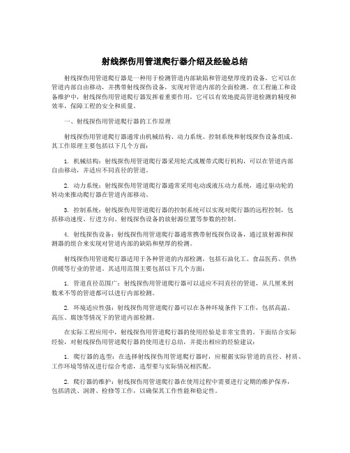
射线探伤用管道爬行器介绍及经验总结射线探伤用管道爬行器是一种用于检测管道内部缺陷和管道壁厚度的设备,它可以在管道内部自由移动,并携带射线探伤设备,实现对管道内部的全面检测。
在工程施工和设备维护中,射线探伤用管道爬行器发挥着重要作用,它可以有效地提高管道检测的精度和效率,保障工程的安全和质量。
一、射线探伤用管道爬行器的工作原理射线探伤用管道爬行器通常由机械结构、动力系统、控制系统和射线探伤设备组成。
其工作原理主要包括以下几个方面:1. 机械结构:射线探伤用管道爬行器采用轮式或履带式爬行机构,可以在管道内部自由移动,并适应不同直径的管道。
2. 动力系统:射线探伤用管道爬行器通常采用电动或液压动力系统,通过驱动轮的转动来推动爬行器在管道内部移动。
3. 控制系统:射线探伤用管道爬行器的控制系统可以实现对爬行器的远程控制,包括移动速度、行进方向、射线探伤设备的放射源位置等参数的控制。
4. 射线探伤设备:射线探伤用管道爬行器通常携带射线探伤设备,通过放射源和探测器的组合来实现对管道内部的缺陷和壁厚的检测。
射线探伤用管道爬行器适用于各种管道的内部检测,包括石油化工、食品医药、供热供暖等行业的管道。
其适用范围主要包括以下几个方面:1. 管道直径范围广:射线探伤用管道爬行器可以适应不同直径的管道,从几厘米到数米不等的管道都可以进行内部检测。
2. 环境适应性强:射线探伤用管道爬行器可以在各种环境条件下工作,包括高温、高压、腐蚀等情况下的管道内部检测。
在实际工程应用中,射线探伤用管道爬行器的使用经验是非常宝贵的。
下面结合实际经验,对射线探伤用管道爬行器的使用进行总结,并提出相应的经验建议:1. 爬行器的选型:在选择射线探伤用管道爬行器时,应根据实际管道的直径、材质、工作环境等情况进行综合考虑,选型要与实际情况相匹配。
2. 爬行器的维护:射线探伤用管道爬行器在使用过程中需要进行定期的维护保养,包括清洗、润滑、检修等工作,以确保其工作性能和稳定性。
射线探伤用管道爬行器介绍及经验总结

射线探伤用管道爬行器介绍及经验总结射线探伤是工业领域中常见的一种质量检测方法,通过射线投射到被检测物体上,再利用感光材料或感光器件来记录射线透射或散射情况,从而获取被检测物体内部的结构和缺陷信息。
在射线探伤过程中,管道是被检测物体中的一种常见形式,而由于管道结构的特殊性,常常需要使用管道爬行器来完成射线探伤任务。
本文将介绍射线探伤用管道爬行器的使用及经验总结。
一、管道爬行器的基本结构和原理1.基本结构射线探伤用管道爬行器的基本结构通常包括底盘、电机、蜗杆传动装置、探头支架、电源供应设备等组成。
底盘通常采用轮胎或履带结构,能够适应不同直径和形状的管道表面,保证爬行器的稳定性和可靠性。
电机提供动力,蜗杆传动装置实现爬行器的前进和后退,同时保证其在管道内的运动轨迹。
探头支架用于固定射线探伤设备,保证其正确、稳定地对管道进行射线探伤。
二、管道爬行器的使用经验总结1.选择合适的爬行器在进行射线探伤任务之前,首先要根据管道的直径、长度、曲率、施工材料等特性,选择合适的管道爬行器。
一般情况下,爬行器的直径应该小于管道的直径,同时要考虑管道内部的曲率和施工材料,确保爬行器能够在管道内稳定、可靠地运动。
2.合理设置探头支架在安装射线探伤设备时,要注意合理设置探头支架,确保其与管道表面的垂直度和平行度,从而保证射线探伤的准确性和可靠性。
3.保证电源供应管道爬行器通常需要外接电源供应设备,因此在进行射线探伤任务之前,要确保电源供应设备能够正常工作,保证管道爬行器的动力系统和探头支架的正常工作。
4.考虑环境因素在进行射线探伤任务时,要充分考虑管道内部的环境因素,如温度、湿度、气体浓度等,并根据具体情况选择合适的探测设备,保证射线探伤任务的顺利进行。
5.保养维护管道爬行器在完成射线探伤任务后,要对管道爬行器进行及时、有效的保养维护,包括清洁、润滑、检查等工作,保证其在下一次任务中的正常工作。
通过以上经验总结,可以更好地使用射线探伤用管道爬行器,确保其在射线探伤任务中的稳定、可靠运行,提高射线探伤效率和准确性。
管道爬行器的设计与分析(全)
管道爬行器的研究与设计
学生:XX
指导教师:XXX
工程领域:机械工程
论文主审人:XXX
XXXXXX
2013 年 9 月
毕业设计(论文)任务书
专业班级姓名 XX
一、课题名称:管道爬行器的研究与设计
二、主要技术指标:
1、爬行器爬行最小内径为450mm,爬行最大内径1100mm
2、机身内径为150mm,外径为200mm机壁厚度最小处为10mm
3、管道爬行满园:400-1000MM
三、工作内容和要求:
1、爬行器总装配图 A0 1 张;相当零件图不少于10张,大小A4-A2之间
2、总电控系统图 A1 1 张
3、全套SolidWorks造型三维图
4、设计说明书 1 份,设计说明书1.5万字以上,分析、计算准确详尽,格式符合“毕业设计
撰写规范”
5、参考文献(不包括教科书)15篇以上,含一篇外文文献并译成中文(5千字)
四、主要参考文献:
1、齐占庆.机床电气控制技术[M].机械工业出版社,1994
2、杨天明.电机与拖动[M].北京大学出版社,2006
3、电机工程手册[M].机械工业出版社,1996
4、李国厚,杨青杰.PLC原理与应用设计[M].化学工业出版社,2005
5、王永章.数控技术[M].高等教育出版社,2001
6、黄立培.电动机控制[M].清华大学出版社,2003
学生(签名)年月日
指导教师(签名)年月日
教研室主任(签名)年月日
系主任(签名)年月日
毕业设计(论文)开题报告。
射线探伤用管道爬行器介绍及经验总结

射线探伤用管道爬行器介绍及经验总结射线探伤用管道爬行器是一种用于管道内进行探伤工作的设备,它可以在狭窄的管道环境中自由移动,并将射线探伤设备带入到需要检测的部位进行探伤工作。
下面是对射线探伤用管道爬行器的介绍及经验总结。
一、管道爬行器的结构和工作原理管道爬行器主要由机械部分和控制部分组成。
机械部分包括底盘、驱动装置、导向装置等;控制部分则包括遥控器、控制线路等。
底盘装有轮子或履带,可以在管道内自由移动,并且能够适应不同直径的管道。
驱动装置主要是通过电动机带动底盘运动,同时还能够调整爬行器的速度和方向。
导向装置则可以帮助爬行器在管道内保持稳定的走向,避免碰撞管道内壁。
管道爬行器的工作原理是利用电动机驱动底盘前进,然后通过控制器控制爬行器的方向和速度。
控制器通过遥控器操作,可以实时控制爬行器的运动。
在进行射线探伤时,爬行器可以携带射线探伤设备进入管道内,并对管道内部进行探测。
探测结果可以通过遥控器上的显示屏显示出来,方便操作人员实时观察。
二、管道爬行器的优点和应用场景管道爬行器具有以下优点:1. 适应性强:可以适应不同直径和形状的管道进行探测。
2.操作灵活:通过遥控操作,可以实时控制爬行器的运动,方便操作人员进行探测工作。
3. 安全性高:由于爬行器可以代替人工进入管道进行探测,可以有效避免人员的安全风险。
4.效率高:爬行器可以在短时间内完成大量的探测工作,提高工作效率。
管道爬行器主要应用于以下场景:1. 管道内部检测:对于长距离的管道,可以使用爬行器进行全程探测,确保管道内部的安全性。
2. 腐蚀检测:爬行器可以将射线探测设备携带到管道内部,对腐蚀情况进行实时监测,及时进行维修和处理。
3. 管道修复:爬行器可以在管道内部携带修复设备,进行管道修复和维护工作,提高修复效率和质量。
三、管道爬行器的经验总结在使用管道爬行器进行射线探测时,需要注意以下几点:1. 设备维护:定期对爬行器进行检查和维护,确保设备的正常运行。
管道爬行器技术方案

技术方案
1,技术方案
我公司原购买的WZP-3型爬行器,只能使用γ源定位。
由于γ源是危险物品,属于国家严控物资,给我们的使用和管理增加了非常大的难度,因此我们考虑将该爬行器的定位方式改为电视监控,同时保留γ源定位方式。
在爬行器上安装红外摄像机及无线视频发射器,在管口安装将无线视频接收器,摄象机检测到的焊缝视频信号经无线视频发射器处理和放大后传送到管道口,管口的无线视频接收器接收到该视频信号后送至视频监视器显示,操作人员即可在视频监视器上观察到爬行器在管道内的具体位置。
另外,在管口和爬行器上各安装一台无线串口服务器,可以实现爬行器与管口之间的信息交换。
爬行器上的无线串口服务器连接爬行器内的PLC,管口的无线串口服务器连接一台人机界面,操作人员可以通过人机界面操作爬行器,并在人机界面上可以看到爬行器的运行数据。
这样就完全实现了电视监控。
2,材料清单
3,技术性能参数:。
[科技]X射线管道爬行器的研制(精)
![[科技]X射线管道爬行器的研制(精)](https://img.taocdn.com/s3/m/ffd93cf519e8b8f67c1cb97b.png)
[科技]X射线管道爬行器的研制X射线管道爬行器的研制摘要:以苏丹输油管道工程无损检测为实例,介绍了三用型X射线管道爬行器的基本原理与应用效果,介绍了具体的研制过程,包括硬件和软件设计过程中应该考虑的一些关键问题,并将辐射场反馈、内定时等新方法应用于管道爬行器。
通过大量的实践检验和技术数据对比,证明此爬行器具有经济、高效的特点。
Summary: Take Sudan Oil transportation pipeline Engineering fo r example, deacriping the prime principle & results of x-ray crawler with there useful ways. And detail development w ith some key factors in hardware & software design, at the same time use radiographic field feedback, inner timing a pipeline crawler with a lot of fact test & technical data, it is sure that this crawler has the economic & fast pro perty.一、前言随着我国石油工业的全面发展,对外承揽石油基建工程的增多,由我国承建的第一条国外大型输油管道─苏丹输油管道工程于一九九八年开始建设,这条管道全长1500公里,直径28英寸(直径711mm),工期一年,要求管道对接焊缝100%射线检测,总检测量将达15万道口以上。
这是一项国际投标工程,如果仍然采用国内惯用的施工手段,定向X射线机双壁单影法检测,无论从施工速度、人员数量还是造价上,都完全不具备竞争能力。
唯一可行的办法就是采用射线管道爬行器拍片,而由于壁厚及标准的原因γ射线管道爬行器在此难以适用,只有采用X射线管道爬行器,它采用内曝光,具有底片质量好、速度快等优点,但需要进口,价格昂贵,日常维护工作量大且维修困难。
一种可调式管道爬行机器人
一种可调式管道爬行机器人摘要:针对石油、化工、天然气及核工业等产业迅速发展,各种管道作为一种重要的物料输送设施,得到了广泛应用。
由于腐蚀、重压等作用,管道不可避免地会出现裂纹、漏孔等现象。
而管道所处的环境往往是人们不易或不能直接接触的,因此,对于管道的检测和维护成了工业生产中的一道难题,管道机器人有巨大需求,本文提出了管道机器人中的一种。
关键词:石油,化工,管道,机器人1.爬行原理的设计充分利用仿尺蠖昆虫的爬行原理,利用曲柄滑块机构实现管道机器人[19]的前行,具体实施过程如下:启动电机,转盘转动,连杆随动受拉力,带动后大滑块向前,后大滑块通过两个后滑杆带动两足收拢,脱离管道侧壁,后大滑块通过滑槽前壁推动后机体往前移动,此时,转盘受到阻力通过电机整体传力至前机体,由于前大滑块已处于滑槽最后面,两个前滑杆带动两个前足向管道两侧撑开,足够大的摩擦力抵抗前机体向后移动,结果只能是后机体往前运动,从而解决了前行问题。
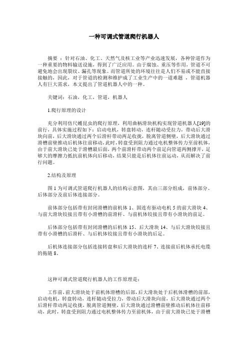
2.结构及原理图1为可调式管道爬行机器人的结构示意图,其由三部分组成,前体部分、后体部分及前后体连接部分。
前体部分包括带有封闭滑槽的前机体1、固连有驱动电机5的前大滑块4、与前大滑块铰接且带有小滑槽的前滑杆、与前机体铰接且带有小滑块的前足。
后体部分包括带有封闭滑槽的后机体15、后大滑块14、与后大滑块铰接且带有小滑槽的后滑杆、与后机体铰接且带有小滑块的后足。
后机体连接部分包括连接转盘和后大滑块的连杆7、连接前后机体承托电缆的拖链8。
这种可调式管道爬行机器人的工作原理是:工作前,前大滑块处于前机体滑槽的后部,后大滑块处于后机体滑槽的前部,启动电机,转盘转动,连杆随动受拉力,带动后大滑块向前,后大滑块通过两个后滑杆带动两足收拢,脱离管道侧壁,后大滑块通过滑槽前壁推动后机体往前移动,此时,转盘受到阻力通过电机整体传力至前机体,由于前大滑块已处于滑槽最后面,两个前滑杆带动两个前足向管道两侧撑开,足够大的摩擦力抵抗前机体向后移动,结果只能是后机体往前运动。
射线探伤用管道爬行器介绍及经验总结

射线探伤用管道爬行器介绍及经验总结1. 引言1.1 射线探伤用管道爬行器介绍射线探伤用管道爬行器是一种专门用于管道内部检测和探伤的装置,通过载有探测设备的爬行器在管道内部移动,实现对管道壁的检测。
该爬行器通常由机械臂、摄像头、传感器等部件组成,可以实时监测管道内部的情况并传输数据给操作人员。
通过射线探伤用管道爬行器,可以有效地检测管道是否存在裂纹、腐蚀、磨损等问题,提高了管道的安全性和可靠性。
射线探伤用管道爬行器的引入,不仅提高了管道检测的精准度和效率,也减轻了人工检测的工作强度和风险。
在石油、化工、航空航天等行业,射线探伤用管道爬行器已经成为不可或缺的检测设备之一。
通过射线探伤用管道爬行器的应用,大大提升了管道设备的安全运行水平,保障了生产和人员的安全。
射线探伤用管道爬行器的介绍,为管道检测工作带来了革命性的变化,使得管道内部检测更加科学、准确和高效。
该技术的不断完善和发展,将进一步推动管道行业的发展,为工业安全保驾护航。
1.2 射线探伤用管道爬行器经验总结在实际应用过程中,我们总结了一些关于射线探伤用管道爬行器的经验,希望可以为后续的工作提供一些指导和参考。
我们发现在操作射线探伤用管道爬行器时,需要注意保持设备的稳定性。
由于管道环境的复杂性,操作员需要具备良好的操作技能和经验,保证设备在工作过程中能够稳定运行。
定期对射线探伤用管道爬行器进行维护保养也是非常重要的。
设备在长时间使用后可能会出现一些故障或磨损,定期进行维护可以延长设备的使用寿命,保证其正常运行。
在选择适合的射线探伤用管道爬行器时,需要考虑其适用的管道直径范围、工作环境等因素,确保选购的设备能够满足实际工作需求。
2. 正文2.1 射线探伤用管道爬行器原理和工作方式射线探伤用管道爬行器利用射线源发射射线,通过管道壁的材料对射线进行衰减,从而形成射线影像。
这些射线影像能够反映管道内部的缺陷情况,如裂纹、腐蚀等。
管道爬行器的工作方式是通过控制器对爬行器进行远程操控,使其在管道内部自主行进。
管道爬行机器人运动分析与变径结构设计

0 引言
在市政尧石油尧化工尧电力等行业袁均存在大量的尧 规格众多的金属管道袁随着使用年限的增长袁需要对这 些管道进行巡检尧维修遥对于从外部无法到达的管道袁使 用管道爬行机器人携带工具进入到管道内部进行巡检尧 维修是一种非常有效的方式遥
了多款轮式尧履带式的爬行机器人袁主要用于市政管网的 检测与维修[4]曰北京德朗检视科技公司开 发 的DNC110B 管 道 机 器 人 可 对 110mm - 800mm 的 管 道 中 进 行 视 频 检 测 袁 也 可 搭 载 机 械 手 进 行 异 物 抓 取 [5]袁 已 在 电 站 的 管 道 检 测中实现了应用遥
Science & Technology Vision
科技视界
管道爬行机器人运动分析与变径结构设计
胡 啸 1* 史 继 新 2 渊 1 . 中 核 武 汉 核 电 运 行 技 术 股 份 有 限 公 司 袁 湖 北 武 汉 430223 曰 2 . 湖 北 省 水 电 机 械 设 备 设 计 与 维 护 重 点 实 验 室 掖 三 峡 大 学 业 袁 湖 北 宜 昌 443002 冤
揖关键词铱管 道 机 器 人 曰 管 道 弯 头 曰 变 径 机 构
中 图 分 类 号 院 TP242
文献标识码院 A
DOI 院 10 . 19694 / j . cnki . issn2095 - 2457 . 2019 . 13 . 001
文 章 编 号 院 2095 - 2457 渊2019冤13-0001-004
Motion Analysis and Diameter Change Structure Design of Pipeline Crawling Robot HU Xiao1* SHI Ji - xin2
管内爬行机器人行走机构的设计

管内爬行机器人行走机构的设计【摘要】随着管内检测爬行机器人技术的不断成熟,它在工业中的应用也越来越广,本文所设计的管内爬行机器人驱动机构,即管内步伐式行走机构,是在分析以往的轮式和履带式机器人的基础上设计的一种新型的管内爬行机器人行走机构。
【关键词】管内爬行机器人;步伐式;驱动机构0.引言目前工业管道系统已广泛应用于冶金、石油、化工及城市水暖供应等领域,因其工作环境非常恶劣,容易发生腐蚀、疲劳破坏或使管道内部潜在缺陷发展成破损而引起泄漏事故等,必须定期地对这些管道进行检修和维护,然而管道所处的环境往往是人力所限或人手不及,检修难度很大, 所以燃气管道管内探测是一项十分重要的实用化工程,关系到燃气的安全、合理地应用和管理。
管道检测机器人(管内爬行机器人驱动机构)就是为满足该需要而产生的。
根据管内步伐式行走机器人的运动模仿人在井筒中四肢扶壁上下运动的模式,设计了机器人的行走机构,有效的解决了机器人在管道内的行走。
1.管内爬行机构总体设计管内爬行机构主要由撑脚机构及其传动,牵引机构及传动,转向机构3部分组成:见图1所示:该管内爬行机构的运动控制过程大致为:主、副电机不同时工作,分别控制其牵引机构和撑脚机构,并且镜面对称的两单元,其支撑脚同一时间径向所处状态相反,即前脚踩在管壁上时,后脚处在抬起状态;反之亦然。
具体过程为通过副电机16带动齿轮与齿圈啮合旋转,齿圈背面的平面螺纹驱动滑杆沿滑道径向移动,从而实现支撑脚的转换。
主电机1通过联轴器与丝杠连接,带动丝杠旋转,将丝杠的旋转运动转换为螺母的轴向移动,从而通过连杆机构拖动身躯和前后单元向前移动,另一部分的控制过程相同。
上述动作是管内爬行机构的一个步进过程,循环执行步进过程机器人继续前进,实现管内的均匀连续行走。
2.撑脚机构及其传动撑脚机构的作用是使管道机器人被支承在管道中心线上。
其机构及传动(见图1)由电机16、小齿轮15、齿圈及平面螺纹14、滑杆13、脚靴12组成。
射线探伤用管道爬行器介绍及经验总结

射线探伤用管道爬行器介绍及经验总结1. 引言1.1 介绍射线探伤用管道爬行器是一种专门用于在管道内进行射线探伤的机器人设备。
它可以自主爬行在管道内部,实时监测管道的内部情况,帮助工作人员快速准确地定位管道内的缺陷或故障。
这种设备通常由机械臂、摄像头、探测器等部件组成,能够完成复杂的探测任务。
射线探伤用管道爬行器在工业领域有着广泛的应用范围,可以用于石油、化工、能源等行业的管道检测和维护。
尤其是在核电站、化工厂等高危环境中,射线探伤用管道爬行器可以取代人工进行探测,降低了工作人员的风险。
射线探伤用管道爬行器的重要性不言而喻。
它不仅提高了管道探测的效率和准确性,还保障了工作人员的安全。
随着工业技术的不断发展和普及,射线探伤用管道爬行器将在未来得到更广泛的应用和推广。
1.2 应用范围射线探伤用管道爬行器是一种应用广泛的工程机器人,主要用于在管道内部进行射线探伤作业。
其应用范围涵盖了许多领域,包括石油化工、电力、核工业、航空航天等行业。
在石油化工领域,射线探伤用管道爬行器可以用于对管道的锈蚀、裂纹等缺陷进行检测,确保管道的安全运行;在电力行业,它可以用于对电力设备的绝缘缺陷进行检测,提高设备的可靠性和安全性;在核工业中,它可以用于对核反应堆管道的裂纹进行检测,确保核设施的安全运行;在航空航天领域,它可以用于飞机引擎管道的检测,确保飞机的飞行安全。
射线探伤用管道爬行器在各个行业都有着重要的应用,为工程检测提供了便利和高效性。
1.3 重要性射线探伤用管道爬行器是一种在工业检测中广泛应用的设备,其重要性不可忽视。
通过射线探伤技术,可以对管道内部进行高精度的检测,及时发现管道内部的缺陷和问题,保障工业生产的安全和稳定性。
射线探伤用管道爬行器可以在复杂的管道结构中进行穿越和检测,避免了人工检测的局限性和误差。
不仅可以有效提高工作效率,也能减少工作人员的安全风险,是一种高效、可靠的管道检测工具。
在工业生产中,管道的安全和稳定性直接关系到生产过程的正常运行和员工的安全,因此射线探伤用管道爬行器的重要性不可忽视。
- 1、下载文档前请自行甄别文档内容的完整性,平台不提供额外的编辑、内容补充、找答案等附加服务。
- 2、"仅部分预览"的文档,不可在线预览部分如存在完整性等问题,可反馈申请退款(可完整预览的文档不适用该条件!)。
- 3、如文档侵犯您的权益,请联系客服反馈,我们会尽快为您处理(人工客服工作时间:9:00-18:30)。
河南科技学院2009届本科毕业论文(设计)论文题目:管道爬行器的研究与设计学生姓名:冯春所在院系:机电学院所学专业:机械设计制造及其自动化导师姓名:杜家熙完成时间:2009年5月20日摘要本课题是在对管道爬行器的结构和运动研究分析的基础上。
本次设计在Solidworks的基础上构建管道爬行器的若干套三维造型,然后依据要求进行选择。
最终方案采用列车连接结构,伸缩结构和“伞”型结构,以适应管道内部的弯道和大范围内径变化管道。
通过电气控制,使各电机顺序动作以完成通过十字型和丁字型等较复杂的管道,通过新型吊环的调节始终保持摄像装置与水平面的平行。
对管道爬行器的控制要求,采用常规的电气控制分析方法设计电气部分的控制电路,最终方案采用人工控制电机的顺序动作进行管道内的转弯,里程计反馈信息与管道工程图相结合的方法来进行爬行器的定位。
为研究管道爬行器打下了一定的基础。
关键词:自适应性,伸缩结构,内径变化,新型吊环,SolidworksThe research and design of piping crawl robotAbstractThe question for discussion base on the structure of piping crawl robot an-d the moving investigation'analyze. This project bases on Solidworks to concei-ve some 3D sculpt of crawl r-obot, then by requestion carry through choose. The final scheme adopt the structure about train and flex structure and umbrell astructure, for the sake of adapting tothe pipeline that can change radius in gr-eat range. And succeed overpassing crossmodel and t-shaped model complicated piping by the sequentially-operation of the electric motor ,and always can keep parallel state between vidicon setting and horizontalgeby adjusting by the new fiying rings system.Gave the request for the contral of piping crawl robot. Ad-opt nomothetic approach about electrical control analysis for control circuit des-ign ofelectric parts.The final project adopt the manual control the electr-ic mot-or’s sequentially-operating make the machine pass the curved conduit.To adopt the way which use milemeter feedback information couple with piping’s sched-ule drawing for allocation.The paper lays the theoretic foundation for research piping crawl robotKeywords: From the adaptability, Flexible structure, Inside the path variety,New fiying rings system,Solidworks目录1 绪论 (1)2 设计方案初步分析 (2)2.1 无线控制与有线控制的选择 (2)2.1.1 有线控制及拖拽 (2)2.1.2 非拖曳 (2)2.2 驱动方式选择 (2)2.2.1 轮式爬行 (3)2.2.2 履带爬行 (3)2.3 姿态调整的选择 (3)2.3.1 加传感器的关节进行调整 (3)2.3.2 利用吊篮方式进行调整 (4)2.3.3 采用新式吊篮进行调整 (4)2.4 自适应分析 (5)2.4.1 伸缩臂长和加弹簧方式 (5)2.4.2 伸缩臂长和“伞”型摇杆 (5)2.5 方案的基本确定 (6)3 方案一的设计与分析 (6)3.1 机身的设计 (7)3.2 机腿的设计 (7)3.2.1 伸缩单元 (8)3.2.2 变长单元 (9)3.2.3 关节单元 (9)3.3 驱动轮的设计 (9)3.4 方案一的分析 (10)4 方案二的设计与分析 (10)4.1 机身的设计 (10)4.2 机身内部传动结构设计 (11)4.3 进给螺杆与螺母的设计 (11)4.4 吊篮的设计 (12)4.5 机腿的设计 (12)4.6 方案二的分析 (13)5 方案三的设计与分析 (13)5.1 机身的设计 (14)5.2 机身内部传动机构的设计 (15)5.2.1 进给丝杠和螺母的设计 (15)5.2.2 选择联轴器 (20)5.2.3 选择键 (20)5.3 吊环的设计 (20)5.4 轴承的设计 (21)5.5 机腿的设计 (21)5.6 驱动轮的设计 (22)5.7 管道爬行的实现 (22)5.8 管道内路口转弯的实现 (23)5.9 总体装配体设计 (24)6 管道爬行机器人的功能分析 (24)7 管道爬行机器人的动作分析 (25)8 电气控制基本元器件的选取 (25)8.1 电机的参数计算与选取 (25)8.1.2 驱动轮电机的参数计算 (25)8.1.3 主电机参数计算 (26)8.1.4 机器人动力源的选取 (27)8.2 电源的选取 (28)8.3 电机调速元件的选取 (28)8.3.1 串联电阻调速方法的实现 (28)8.3.2 新型调节脉宽PWM型调速的实现 (29)8.3.3电机调速方法的确定及元件的确定 (30)9 电路设计 (31)9.1 轮足电机动作的正转与反转的电路设计 (31)9.2 前后伞足的张开闭合电路设计 (32)9.3 电机部分总电路设计 (32)9.4 电机顺序动作的电路设计 (33)9.4.1 人为控制 (34)9.4.2 逻辑控制 (34)9.4.3 单片机/PLC进行自动控制 (34)9.5 照明系统的电路设计 (36)9.6 管道内机器人定位系统(PDPS)的设计 (37)9.6.1 爬行器管道内定位方案的提出与分析 (37)9.6.2 机器人定位系统部件的选择与设计 (39)10 结论 (40)11 结束语 (42)致谢 (43)参考文献 (43)1 绪论随着社会的发展和人民生活水平的提高,天然气管道以及各种输送管道的应用越来越多。
在我国及世界各个国家内,由于地形的限制和土地资源的有限,在地下都埋设了很多的输送管道,例如,一方面天然气管道、石油管道等,在埋有管道的地面上都已经建成了很多的建筑物、公路等,给管道的维修和维护造成了很大的困难。
当这些管道由于某些原因造成了泄露、堵塞等问题时,人们普通的做法是挖开道路进行维修,有些时候如果不能准确判断泄露和堵塞的具体位置时,会浪费很多的时间和精力,同时降低了工作效率[7]。
另一方面石油、天然气、化工、电力、冶金等工业的管道工程大多采用焊接管路。
为了保证焊接管路的焊接质量和运行安全,管道工程都要对焊缝进行检测,检测焊接部位是否存在虚焊、漏焊、伤痕等焊接缺陷。
常用的焊缝检测方法是采用无损检测,如超声、射线、涡流等。
对于管路检测,则大多采用管道内爬行探伤检验设备(简称爬行器) 对焊缝进行射线检测。
这类爬行器由于受管道尺寸的限制,大多结构十分紧凑。
在检测过程中,爬行器在其控制系统的控制下,可连续对同一管道不同位置上的焊缝质量进行检验。
考虑管道焊缝检测的效率,常常当管道焊接具有一定长度之后,才集中对管道进行检测。
如果一次要检测的管道比较长,爬行器的控制系统应采用车载式布置。
使用时,通过外部的控制器对爬行器上的控制系统发出指令,决定爬行器的工作状态。
随着机电一体化技术的发展,以及机器人技术的发展和管道测试等技术的进一步发展,相互之间的渗透程度越来越深,管道爬行机器人是在狭窄空间中进行精密操作、检测或作业的机器人系统。
其中机器人的作业环境一般是危险的。
火力发电厂、核电厂、化工厂、民用建筑等用到各种各小管道,其安全使用需要定期检修。
但由于窄小空间的限制,自动维修存在一定难度。
仅以核电站为例,检查时工人劳动条件恶劣。
因此管道内机器人化自动检查技术的研究与应用十分必要。
人们不再为了维修、维护管道时挖开道路,节省了大量的人力,物力和财力。
目前的管道机器人都是以履带、轮子等实现在管道中的移动,其技术有着或多或少的缺陷,市场尚不成熟。
例如:不能适应大范围的管道内径变化,运行中姿态的调整不够理想,在十字型、丁字型等较复杂的管道内径中不能较平稳的通过等等;结合目前管道机器人所存在的缺点,应用机械设计、机械原理等专业知识,设计出了新型管道爬行机器人。
此机器人可实现大范围内的管道内径变化,顺利通过十字型、丁字型等较复杂管道;在运行中的姿态调整也得到了较好的解决。
2 设计方案初步分析2.1 无线控制与有线控制的选择2.1.1 有线控制及拖拽该方式采用机器人尾部装夹电缆、信号线、安全绳、其他电路等等,这样会造成机器人的牵引力增大,对爬行器的负载力和足轮的摩擦力提出了更高的要求,尤其是随着机器人的深入,牵引绳会成为机器人的累赘和枷锁。
牵引绳的长短禁锢着机器人的爬行深度。
其优缺点如下:缺点:附着力会不断增大,爬行器负载变化大,不利于长距离爬行。
优点:爬行器本身初始载重小(本身不需携带能源等),信息反馈及时清晰,利于后期观察,也利于实现在线监控。
观察结束时,可人工使用安全绳退出。
2.1.2 非拖曳该方式不需跟随电缆线,本身有拍摄存储功能,并且本身携带电源等,其优缺点如下:缺点:爬行器本身载重加大,需设计爬行器退出管道方式等。
优点:爬行器载重恒定,便于爬行器爬行。
其在管道内行进方便,尤其在弯道时,拖曳式的过大的牵引力会使爬行器驱动轮打滑,不易通过。
根据要求,非拖曳虽有自己强大优点,但爬行器在管道内出现问题而不能移动时,需要花费很大力气将爬行器取出。
