印刷机DEK刮刀使用手册
dek中文版操作手册
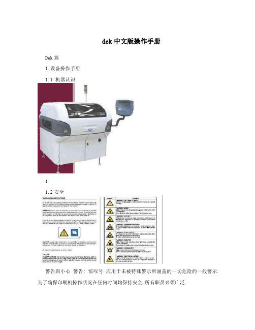
dek中文版操作手册Dek篇1.设备操作手册1.1 机器认识11.2安全警告與小心警告: 惊叹号应用于未被特殊警示所涵盖的一切危险的一般警示. 为了确保印刷机操作状况在任何时间均保持安全,所有职员必须广泛地遵守并接受除在手册描述之特别安全注意事项外之安全规范. 警告定義警告: 切割物在警示卷标附近存在锐利边缘伤害的危险.当在指定警告标示引起作业员与保养员对可造成死亡,重伤或病症的可能危区域工作时需特别小心. 险的注意.这些危险不是设备固有就是在设备操作时产生出来的.在机器上使用的警告卷标的范例展示于另一边的表格内. 警告: 刺激物存在会立即产生发炎的物质,并会重复或延长与黏膜底下展示的结合警告和小心预防的卷标,贴于机台上意味着使用者尝或皮肤的接触. 试在设备上执行此作业前应先参阅技术参考手册内相关章节内容. 警告: 易燃物存在易燃物质,应远离热,燃烧源与静电放电,使用于通风良好区域.警告: 移动物在警示卷标附近存在移动对象,这些对象有能力造成伤害.设备外盖不可移开.警告: 辐射物小心标示警告职员随着偏离描述步骤所可能引发的人或料可能的在卷标附近存在因雷射光造成眼睛伤害的危险.不要损害.小心标示并不意味对职员的危险. 直视光源或物体表面之直接反射光.一个小心标示的例子如下: 警告: 受压物高压存在并可能造成伤害.不要企图直接开启系统至小心大气下.摄影机损毁..不要留下任何未用治具于升降平台的后轨道后方区域. 如有任何物体留在升降平台的PC板印刷区域外,当平台上升至印刷警告: 电力危险高电压存在并可能造成伤害或死亡.不要从设备外罩高度时,它将可能与摄影机相撞.移除保护盖或不顾保护装置.21.3设备概观範圍這手冊應由適當訓練過的設備操作人員來使用.對於設備的一般操作狀況它是個快速入門指南.關於設備設定更深一層的資訊則總括到技術參考手冊項次說明觸控式螢幕 1系統按鈕 2滑鼠 3雙按鈕控制 4 鍵盤 5主電源開關 6 緊急開關按鈕 7 錫膏滾動燈 8 三色燈 9 當機器啟動電源後,按下兩紅色緊急開關中任一能以受控方式使機器停止31.4人机接口狀態頁模式2在主要控制螢幕上所顯示的資訊為狀態頁.狀態頁有兩種版本顯示模式.可在Set Prefs選單內Display Type螢幕顯示模式做選擇模式1項次說明製程參數視窗 1設備參數視窗 2訊息提示帶 3項次說明項目單 4 印刷機主題視窗視覺資料視窗 1 5警告訊息視窗 6 製程參數視窗 2印刷機狀態視窗 7 訊息提示帶 3 印刷機主題視窗 8 項目單 4 在觸控式螢幕上觸壓相關的項目圖像便能完成功能選視覺資料視窗 5 擇.另一種選擇方式是藉由鍵盤上功能鍵F1到F8來做警告訊息視窗 6 選擇印刷機狀態視窗 74視覺資料視窗可利用在狀態頁上的Zoom In或 Zoom Out 圖像來改變視覺資料視窗的大小.51.5三色灯此訊息燈顯示設備的作動狀態.設備無法作動系統電源關閉錯誤訊息顯示設備未在準備狀態作動狀態燈號顏色設備在初始化設備在設定中設備在維護下設備提示操作者注意卡匣錫膏不足擦拭紙卷用盡擦拭溶劑耗盡設備可作動設備在就緒狀態等待61.6 开机与登入3. 觸壓Monitor (鍵盤上F7功能鍵). 1. 旋轉主電源開關至ON處.4. 觸壓Log On (F1).2. 設備提示時按壓System鈕.操作員登入視窗顯示:已選好的狀態頁模式會與下列功能選單一起顯示:使用鍵盤輸入操作員I.D.後按下Enter 鍵.5. 觸壓Exit (F8).71.7产品换线新產品 4. 觸壓Load (F1).1. 觸壓Setup (F6).5. 觸壓Change Screen (F5). 2. 觸壓Load Data (F2).選定的檔案會顯示在狀態頁.儲存於設備內所有產品檔案表會顯示出來: 6. 系統提示時掀起前方印刷頭蓋.3. 使用Left, Right, Up和Down (F4, F5, F6和F7) 反白所需檔案.87. 移出钢板. 10. 按下System 鈕.11. 触压Change Screen (F5).8. 加载新钢板到机器内并确保正确方位与开孔位置.12. 触压Change Tooling (F6).13. 触压Head (F2).9. 放下前方印刷頭蓋. 14. 使用双控制钮抬起印刷头.915. 装上印刷头支撑杆 16. 调整PC板支撑器至适合产品位置来准备印刷.PC板夾板器. 當在機器支撐器置放區作業時需極端小17. 移开印刷头支撑杆并归回原位. 心夾板系統且必須經過練習以避免傷害.在前方和後方夾板系統上的金屬薄片是非常鋒利的DEK建議只有操作員能更換磁性支撐桿.使用其它支撐器或許需要變更PC板狀態檔.小心攝影機損毀..不要留下任何未用治具於升降平台的後軌道18. 触压Head (F2).後方區域.如有任何物體留在升降平台的PC板印刷區域外,當平台上升至印刷高度時,它將可能與攝影機相撞.1019. 使用雙控制鈕放下印刷頭.20. 按下System紐.21. 触压Exit (F8).22. 觸壓Exit (F8).111.8印刷参数调整自動模式批量印刷1. 觸壓Setup (F6). 1. 觸壓Monitor (F7).2. 觸壓Mode (F1) 直到Auto出現在狀態頁的模式選項上 2. 觸壓Batch Limit (F4).3. 觸壓Exit (F8). 批量計數極值視窗會顯示在螢幕上:4. 觸壓Run (F1). 3. 使用微調鍵Incr.及Decr. (F6和F7) 可設定所需批量數.印刷機將連續不斷地運作. 4. 觸壓Exit (F8).12除程式設定的鋼板擦拭週期外可選擇Clean Screen來啟動擦拭5. 触压Exit (F8). 鋼板動作.6. 触压Run (F1).除程式設定的錫膏攪拌週期外可選擇Knead Paste來啟動攪拌錫膏動作.印刷選單當設備於自動模式下運作時會顯示下列選單:如有安裝擠壓式刮刀頭選用配備則錫膏添加功能將取消.選擇Paste Load添加錫膏有兩種方式 (自動加錫和手動加錫).选择 End Run可停止印刷机于完成该印刷周期选择 Stop Cycle将立即停止印刷在印刷期間的任何階段皆能啟用下述功能錫膏添加擦拭鋼板參數調整攪拌錫膏調整檢查作業員不應該使用參數調整及調整檢查.133. 添加錫膏到鋼板上. 添加錫膏锡膏和溶剂. 当使用或处理任何锡膏或溶剂必须严格地遵守制造商的标准安全注意事项.防护衣物. 当处理锡膏和溶剂时随即穿戴合格的防护衣物来减少挥发气体的吸入,眼睛及皮肤的接触与摄取.4. 關上前方印刷頭蓋. 手動添加1. 觸壓Manual Load (F2).‘打開前蓋並添加錫膏’ 訊息會顯示在螢幕上2. 打開前方印刷頭蓋.5. 按下System紐.146. 觸壓Continue (F1).7. 觸壓Exit (F8).自動添加1. 觸壓Auto Dispense (F1).錫膏添加器將執行錫膏自動添加作業.2. 觸壓Exit (F8).15溶劑重新補充溶劑至溶劑桶建议溶剂. 任何溶剂的使用必须符合当地环保规章. DEK推荐使用环保认可的溶剂,换句话说无CFC与含水基成分.使用的溶剂必须拥有快速挥发速率及闪火o点规格高于39C的特性. 溶剂溶液. 勿将不同溶剂的溶液混合.当更换另一种不同溶剂时必须彻底冲洗干净溶剂桶.16易燃性. 存在易燃性物质.应远离热,燃烧源与静电放电.3. 裝上印刷頭支撐桿于通风良好区域使用溶剂喷洒. 钢板擦拭清洁器喷洒一细微溶剂溶液喷射带在清洁器纸卷上.应穿著经认可之防护衣物从事作业.受压容器. 溶剂桶是充满压力的状态;在打开溶剂桶注入盖前必须先释放压力.4. 小心旋開溶劑蓋子使蒸氣壓力消去. 重新補充溶劑至溶劑桶:1. 觸壓Head (F2).2. 使用雙控制鈕抬起印刷頭.5. 打開蓋子使用漏斗重新補充溶劑.176. 旋緊蓋子. 9. 移開印刷頭支撐桿並歸回原位.7. 觸壓Prime Solvent (F6).10. 觸壓Head (F2).‘同時按壓兩控制鈕來汲取溶劑’ 訊息會顯示在螢幕上.8. 使用螢幕兩旁控制鈕來汲取溶劑. 11. 使用雙控制鈕放下印刷頭.12. 按下System鈕.18物品更换卷紙 3. 裝上印刷頭支撐桿易燃性. 使用過之紙卷含有鋼板擦拭清潔器溶劑及錫膏的殘留物.參考製造供應商所建議的拋棄處理指示.防護衣物. 當處理錫膏和溶劑時隨即穿戴合格的防護衣物來減少揮發氣體的吸入,眼睛及皮膚的接觸與攝取.4. 小心移開髒污的紙卷.1. 觸壓Head (F2). 5. 裝上新紙卷並依照下圖路徑纏繞:2. 使用雙控制鈕抬起印刷頭.項次說明擦拭紙卷 1收集紙桿 2196. 觸壓Prime Paper (F5). 10. 使用雙控制鈕放下印刷頭. ‘按壓兩控制鈕來進紙’ 訊息會顯示在螢幕上.7. 使用螢幕兩旁控制鈕捲動紙卷確保紙能正確地供給. 11. 按下System鈕.刮刀8. 移開印刷頭支撐桿並歸回原位. 1. 觸壓Setup (F6). 2. 觸壓Setup Squeegee (F4). 9. 觸壓Head (F2).203. 觸壓Change Squeegee (F1). 8. 觸壓Continue (F1).4. 打開前方印刷頭蓋.刮刀參考高度9. 觸壓Calibrat Heights (F2).‘在開始進行壓力校正前先移出鋼板’ 訊息會顯示在螢幕上. 5. 換上所需的刮刀6. 關上前方印刷頭蓋 10. 觸壓Exit (F8).11. 觸壓Change Screen (F5).7. 按下System鈕.‘移出鋼板’ 訊息會顯示在螢幕上.2115. 按下System鈕. 12. 打開前方印刷頭蓋.16. 觸壓Setup Squeegee (F4).13. 移出鋼板.17. 觸壓Calibrat Heights (F2).‘確保安裝正確的刮刀’ 訊息會顯示在螢幕上. 14. 關上前方印刷頭蓋 18. 觸壓Continue (F1).‘壓力高度校正中-勿開啟前蓋’ 訊息會顯示在螢幕上.19. 觸壓Exit (F8).2223. 關上前方印刷頭蓋 20. 觸壓Change Screen (F5).‘插入鋼板並重試’ 訊息會顯示在螢幕上.21. 打開前方印刷頭蓋.24. 按下System鈕.22. 載入鋼板到印刷機內並確保正確方位與開孔位置. 25. 觸壓Change Screen (F5).26. 觸壓Exit (F8).231.9注销与关机1. 觸壓Monitor (F7). 5. 當被提示確認是否關機.2. 觸壓Log Off (F1).6. 當螢幕顯示’現在關閉你的電腦是安全的’ 訊息時,旋轉主電源開關至OFF位置3. 觸壓Exit (F8).4. 觸壓狀態頁上Close System圖像.24错误讯息下述表格列出在正常印刷操作下可能發生的錯誤訊息,可能原因及解決方法.完整版的設備錯誤訊息在技術參考手冊中.補充鋼板清潔擦拭系統溶劑. 鋼板清潔擦拭系統溶劑不足清潔溶劑不足需要補充.鋼板清潔擦拭系統紙卷需要更換鋼板清潔擦拭系統紙卷. 無清潔擦拭紙更換.錫膏筒內無錫膏/擠壓錫膏添加器錫膏筒內無錫膏更換錫膏添加器內錫膏筒. 式刮刀頭錫膏卡匣內補充/更換擠壓式刮刀頭內錫膏卡匣. 或擠壓式刮刀頭錫膏卡匣必錫膏量不足須補充更換.軌道上升異常,檢查支在升降平台上有支撐器/物體打開前方印刷頭蓋移出在升降平台上軌道下的支撐器頂撞到軌道下方. 撐器或物體.系統斷電印刷頭蓋掀起或E Stop觸壓. 關上印刷頭蓋.釋放E Stop紐關上印刷頭蓋. 前蓋打開時系統暫停印刷頭蓋掀起.PC板未到達定位或印刷完打開前方印刷頭蓋,鬆開夾板器並將PC板從軌道內PC板停在軌道上成後未送出板子. 移出.25下面是赠送的企业管理名句100,欢迎欣赏!!!!!!关于企业管理的名言名句5、对产品质量来说,不是100分就是0分。
DEK印刷机操作标准书
(c).當屏幕出現"now you can turn off power"時﹐關掉主電源。
7.附件:SMT印刷刮刀更換履歷表。
SMT印刷刮刀更換履歷表
序號
刮刀材質
刮刀更換次數
印刷PCB次數
更換者
確認者
更換日期
備注與說明
1
1.鋁合金材質的刮刀﹐印刷次數為25萬次后作報廢處理。(更換新刮刀)。2.橡膠材質的刮刀﹐印刷次數為30萬次后作報廢處理。(更換新刮刀)。
(b).按下change Tooling(F6),再按下open cover(F2),調整頂針,并放入鋼板。
(c).按下system鍵﹐然后按下Home deaner(F3),按Exit(F8)復位。并按Change screen(F5)確認已更換鋼板﹐最后按下Exit(F8)復位。
c.自動模式(AUTO MODE)生產
(b).鋁合金材質的刮刀﹐印刷次數為25萬次后作報廢處理。(更換新刮刀)。
(c).橡膠材質的刮刀﹐印刷次數為30萬次后作報廢處理。(更換新刮刀)。
i.量出PCB板的各參數﹐放至輸送軌道﹐找到Mark點﹐將Mark點各參數存檔﹐并將印刷狀態調至Auto Print按下RUN(F1)。
j.關機
(a).在狀態頁按下Close system。
g.安裝擦拭紙(Paper roll)
(a).按下Open cover(F2)﹐再按change screen (F2),換上新的擦試紙﹐并按下change screen確認后再復位。
h.安裝刮刀
(a).按下Setup(F6)及按下Setup squeegee(F4)到Change squeegee(F1)﹐待有信息提示時裝上所需刮刀并調整刮刀的高度﹐按下Save(F3)存檔﹐并按Exit(F8)復位。
DEK基本操作说明书
DEK 操作说明一:机器安全标志这章主要介绍DEK机器部的各个安全标志、ESD防标志等。
它们都处于机器部或者外部比较显眼的地方。
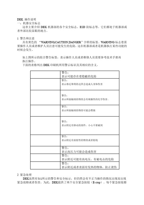
1 警告和注意具有黄色的“WARNING,CAUTION,DANGER”字样的标签。
WARNING标志着需要操作人员或者维护人员注意可能发生的危险,这在机器部或者是机器执行某些功能的时候会发生。
如上图所示的组合警告标签,表示操作人员或者维修人员需要参考技术手册再执行操作。
下面的表格列出DEK印刷机所用警示标识及其相应的含义。
2 紧急处理DEK虽然有如1所示的警告和安全标示,但仍然会有不正当操作的情况出现而出现紧急故障或者伤害,为此,DEK提供了两个安全紧急按钮(E-stop)。
每个紧急按钮都能使机器急停,从而避免伤害。
如图所示,在机器前台的两端都有红色的按钮就是E-stop。
图1 紧急按钮位置二机器概述1如图所示为机器外部概貌①机器控制屏幕(Main Control Screen)②两侧的控制按钮(Two Button Control)③小鼠标(Mouse Trackball)④键盘(Keyboard)⑤系统启动按钮(System Button)⑥红色紧急按钮(Emergency Stop Button,E-stop)⑦主电源开关(Main Isolator)⑧印刷监控灯(Paste Roll Lamp)⑨机器状态灯(Tricoloured Beacon)2 机器控制屏幕的两种显示方式,如图所示Type1①印刷标题栏(Printe Title)②制程参数窗口(Process Parameter)③消息提示栏(Message Prompt)④主菜单(Main Menu)⑤视频窗口(Vision Data)⑥警告消息窗口(Warning Message)⑦印刷状态窗口(Printer Status)Type2①制程参数窗口(Process Parameter)②机器参数窗口(Machine Parameter)③消息提示栏(Message Prompt)④主菜单(Main Menu)⑤视频窗口(Vision Data)⑥警告消息窗口(Warning Message)⑦印刷状态窗口(Printer Status)⑧印刷标题栏(Printe Title)这两种方式可以通过Zoom in或者Zoom out来转换。
印刷机操作手册_DEK265
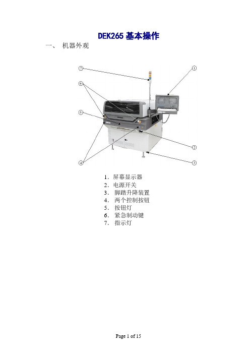
DEK265基本操作一、机器外观1.屏幕显示器2.电源开关3.脚踏升降装置4.两个控制按钮5.按钮灯6.紧急制动键7.指示灯二、开机1. 检查机器内部有无异物,电源、气压是否正常。
2. 打开机器电源开关,释放紧急制动键。
3. 当显示屏幕上出现press system switch to initialize printer字样时,在控制面板上按下绿色SYSTEN键,机器执行初始化,开机动作完成。
三、拆卸与安装钢网1.按setup键2.按change screen键3.打开机器前盖4.将机器内钢网取出5.将新钢网插入机器内6.放下机器前盖7.按system键四、拆卸与安装刮刀1.按setup键2.按set up squeegee键3.按change squeegee键4.打开机器前盖5.装后刮刀,注意检查刀座水平、刀口方向及螺丝是否拧紧6.装前刮刀,注意检查刀座水平、刀口方向及螺丝是否锁紧7.放下机器前盖8.按system键五、更换擦网纸和溶剂补充1. 按head键2.按下两个控制键升起机器印刷头,用支撑棒顶住印刷头.3.打开溶剂盒的螺旋盖,倒入溶剂,再扭紧螺旋盖.4.取下已用完的擦网纸a bc d5.换上新的擦网纸a b c d e f正确的擦网方向图示6. 取开支撑棒, 按下两个控制键降下印刷头.7.按下system键六、添加锡浆机器准备运行时添加锡浆1.按Paste Load键2.按Manual Load键3.打开机器前盖4.将锡浆凃覆于钢网上5.放下机器前盖6. 按system键7.按Continue键8. 按Exit键机器运行时添加锡浆 1.按Paste Load键2. 按Manual Load键3. 打开机器前盖4. 将锡浆凃覆于钢网上5.放下机器前盖6. 按system键7. 按Continue键8. 按Exit键七、生产运行1.按Setup键2.按Mode键,在显示屏幕上为Auto模式3.按Exit键4.按Run键机器正常生产时的显示菜单为:按End Run键为机器在完成当块印刷后停止工作按Stop Cycle键为机器立刻停止动作按 Paste Load键为加入新锡浆按Clean Screen键为清洗钢网八、关机1.检查机器内部有无异物。
DEK操作手册
人機介面
視覺資料視窗
可利用在狀態頁上的 Zoom In 或 Zoom Out 圖像來改變視覺資 料視窗的大小.
三色燈
此訊息燈顯示設備的作動狀態.
燈號顏色
作動狀態 設備無法作動
系統電源關閉 錯誤訊息顯示
設備未在準備狀態 設備在初始化 設備在設定中 設備在維護下
設備提示操作者注意 卡匣錫膏不足 擦拭紙卷用盡 擦拭溶劑耗盡
人機介面三色燈印刷產品耗材補充物品?換登出與關機安全警告與小心為?確保印刷機操作?況在任何時間均保持安全所有職員必須廣泛地遵守並接受除在手冊描述之特別安全注意事項外之安全規範
設備操作手冊 ......步進式指導
安全 設備概觀 人機介面 三色燈 開機與登入 產品換線 印刷產品 耗材補充 物品更換 登出與關機 錯誤訊息
4. 小心旋開溶劑蓋子使蒸氣壓力消去.
2. 使用雙控制鈕抬起印刷頭.
5. 打開蓋子使用漏斗重新補充溶劑.
6. 旋緊蓋子.
耗材補充
9. 移開印刷頭支撐桿並歸回原位.
7. 觸壓 Prime Solvent (F6).
‘同時按壓兩控制鈕來汲取溶劑’ 訊息會顯示在螢幕上. 8. 使用螢幕兩旁控制鈕來汲取溶劑.
新產品
1. 觸壓 Setup (F6).
2. 觸壓 Load Data (F2).
儲存於設備內所有產品檔案表會顯示出來:
產品換線
4. 觸壓 Load (F1).
選定的檔案會顯示在狀態頁. 5. 觸壓 Change Screen (F5).
6. 系統提示時掀起前方印刷頭蓋.
3. 使用 Left, Right, Up 和 Down (F4, F5, F6 和 F7) 反白所需檔案.
7. 按下 System 鈕.
DEK中文操作说明书
B I G邦扬国际股份有限公司BIG: Leo Wang265 Infinity/Horizon/ELA 操作说明书人机界面(OPERATOR/MACHINE INTERFACE):这个界面介于机器与操作者之间来完成动作,其所使用的两个显示器位于机器之右上方,由八个功能键来控制机器,位于右边彩色萤幕下面或位于触控萤幕下方,这些功能键用时加以说明在显示器上,所有机器的功能操作可由功能键快速的进入,或者由键盘输入作为选择,功能键与键盘F1-F8是相同的作用。
(图1)(图1)印刷机状态(Printer Status):状态(Status): 标明目前印刷机的状态; 待机(Ready)模式(Mode): 标明目前印刷机的模式; 自动(Auto); 单片(Single); 单一步(Step); 不印刷(No Print)可当输送带使用操作员(Operator): 可登录可不登录生产程式(Product): 生产程式名称资料登录(Data Logging): 可启动可不启动远端监控(Host Comms): 选配功能可启动可不启动温度(Temperature): 机器内部温度显示周期时间(Cycle Time): 印刷周期时间显示穿越时间(Throughput): 生产周期时间显示软体版本(SW Version):机器版本显示生产参数(Process Parameters):印刷模式(Printer Mode):前刮刀印刷速度(Front Printer Speed): 前刮刀印刷速度显示 1 2 3 4 5 6 7 1 2后刮刀印刷速度(Rear Printer Speed): 后刮刀印刷速度显示前刮刀压力(Front Pressure): 前刮刀压力显示后刮刀压力(Rear Pressure): 后刮刀压力显示脱模速度(Separation Speed): 脱模速度显示数量(Rates): 批次数量(Batch Count/Limit): 显示此批生产数量生产板数(Board Count/Limit): 显示已生产数量清洁钢板次数1(Clean 1 Count/Rate): 显示清洁钢板次数模组1清洁钢板次数2(Clean 2 Count/Rate): 显示清洁钢板次数模组2刮刀印刷方向(Print Direction): 显示刮刀印刷方向影像视窗: 同时监看钢板及PC 板的视觉点(Fiducial mark)系统关闭键影像视窗放大/缩小键功能操作键●265 INFINITY/HORIZON/ELA 画面:这个资讯显示机器的状态,使用者可以设定显示的方式,可以在编辑的项目(Edit data),在Display Type 的项目有Type1与Type2两种可以设定265INFINITY/HORIZON/ELA 画面。
2-DEK机印刷参数设定操作指导书
(1)印刷速度应与刮刀压力相对应,过快的速度会导致锡膏对刮刀压力产生过大的反作用力,而使实际刮刀压力加在钢网表面的力下降,致使表面有一层薄锡存在,模厚增加。
(2)由于细间距IC的孔壁面积与底面积之比较小,其脱模的质量对脱模速度较敏感,过快的脱模速度会影响锡膏的成型,出现拉尖,桥联现象。
7 改进措施:
细间距IC印刷参数控制值建议如下:
PCB板厚:PCB实际厚度-0.1MM DWELL高度:30MM
印刷速度:20~30MM/S DWELL速度:24MM/S
刮刀压力:14英寸刮刀:5.6~6.6KG, 21英寸刮刀:9~10KG
擦网方式:W/V/D 擦网速度:20~40MM/S
擦网频率:一般3PCS/1次,含较多BGA或细间距IC者,1~2PCS/1次。
DEK印刷机SOP
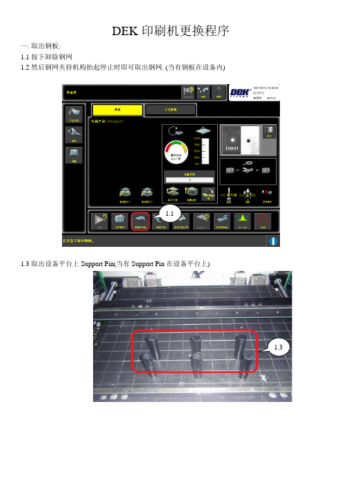
DEK印刷机更换程序一.取出钢板:1.1按下卸除钢网1.2然后钢网夹持机构抬起停止时即可取出钢网. (当有钢板在设备内)1.11.3取出设备平台上Support Pin(当有Support Pin在设备平台上)1.3二.调用程序: 2.1按下产品设定2.2选择所要生产的程序并按下调用 2.3然后按下返回-回到产品设定画面三.摆放支撑Pin: 3.1按下支撑 3.2按下设置支撑 3.3按下装载基板 3.4按下自动进板2.12.2.12.32.2.23.13.23.33.43.4.1待照相机归零后,先将透明罩板贴在板子上然后按夹板器把板子移开,再按视觉对位高度后根据透明罩板进行摆放支撑Pin.3.4.13.4.33.4.23.53.5摆好支撑Pin按下卸除基板再按返回退回到产品设定画面四.更换刮刀4.1按下刮刀4.2按下更换刮刀,然后依据板子长度大小更换符合的刮刀并锁紧在刮刀座上,再按返回退回到产品设定画面4.14.2.14.2五.放置钢网:5.1按下安装钢网,将钢网推到底再按确认即可5.1 5.1.1六. 基板基准点的对位: 6.1按下对位 6.2按下装载基板6.3对位按下检查对位, 设备平台会将板子升起贴平钢网确认是否准确6.4确认没问题后,按继续让板子降下6.5如有偏移则可依偏差调整补偿值(红色框框内X 、Y 、θ) 6.6按卸除基板后,再按自动出板将板子拿起来6.16.26.56.46.36.5七.印刷生产:7.1在准备好的状态下按下印刷即可生产八.更换清洁纸:8.1在准备好的状态下(没有印刷时)按下卸除钢网8.2然后钢网夹持机构抬起停止时即可将钢网推到里面. (当有钢板在设备内)8.3将用完的纸卷拿掉换上新的纸卷,纸卷贴着滚轮然后再用夹杆插入Pin 的位置,旋转夹好纸卷即可 继续生产7.18.18.28.38.3.18.3.2。
DEK印刷机操作手册
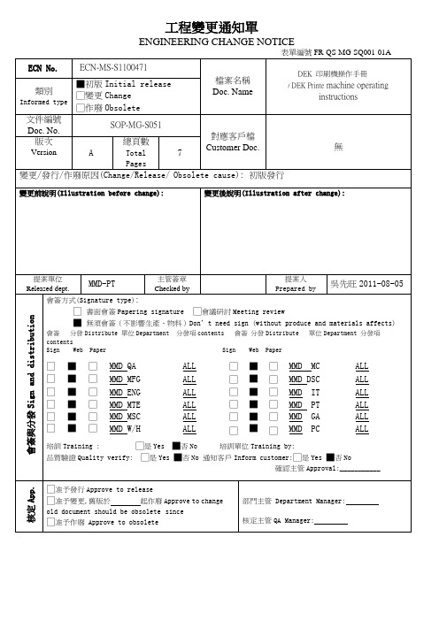
工程變更通知單ENGINEERING CHANGE NOTICE******** 目錄********項目(Item) 內容(Description) 頁次(Page)目錄/content 1修訂履歷revision 21 目的/Purpose 12 使用範圍/Scope 13 機台簡介/Machine introduction 14 機台操作/Machine operator 1-25 注意事項/Caution statement 26 設備保養/Maintenance 27 錫膏的使用/Solder paste usage 38 鋼板擦試/Cleaning screen 39 附表/An attached table 3-4-510 關鍵備件/Key parts list 5修訂履歷Revision History质量保证操作系统DEK 印刷機操作手冊/DEK printermachine operating instructionsPAGE 1/5REV A1.目的/Purpose為了使操作員更好的瞭解印刷機的基本操作,並給初學者以指導. /In order to make the opereator to know more of the printer basic opereate,and give a direct to the beginner.2.使用範圍/ScopeDEK265印刷機./DEK265 printer3. 機台名稱與參數簡介/equipment appellation and parameter introduceMODEL:DEK265AC:220V 50/60HZ 20A AIR:5~7kg f/cm² BOARD WIDTH:42.5~508.5mmPRESSURE:0~20kg SPEED:2~150mm/s BOARD LENGTH:50~510mm4.機台操作/equipment opereation4.1 開機/start machine4.1.1 將AVR 的開關置ON./Take the AVR switch to ON.4.1.2 將Mains Lsolator Switch 置ON./Take Mains Lsolator Switch to ON. 4.1.3 開機進入主書面後根據提示按亮電腦下方的藍色按鈕(Systen Switch)./According to the suggestion to press light the blue button in the lower of computer(System Switch ) after enter the 注:"Mains Lsolator Switch"是DEK 印刷機正前方右門左上角的旋鈕./"Mains Lsolator Switch "is left the botton that on the top of the front right door . 4.2 印刷機換線/Printer changeing line.4.2.1 將支撐Pin 移至安全處./Take the support Pin to safe place. 4.2.2 量測PCB 板的長.寬.高./Survey the long,wide and depth of PCB board.4.2.3 調整/Adjust Stencil(PCB 板的寬度等於印刷機Stencil 架右側手輪的數值,換新版次更換Stencil). 4.2.4 點擊Load Data 換新版次選擇Edit Data 並參照4.3)選擇檔案名./Attack to Load data change new edition ,choose Edit Data and files name (and refer to 4.3). 4.2.5 將支撐Pin 調好(並參照5.3)/Adjust to the support Pin. 4.2.6 加錫膏(並參照7)/Add paste. 4.2.7 點擊Run./Attack RUN.4.3 新程式製作/Edit new program.4.3.1 開機進入主書面./Start machine and enter the main panel.4.3.2 點擊Setup 選擇Edit Data 可進入編輯書面./Attack Setup and choose Edit Data to enter the edit panel. 4.3.3 根據提示進行編輯(輸入檔案名,PCB 板的長寬高,Mark 點的X, Y 座標,前後刮刀的壓力以及印刷速度.擦拭的模式.頻率和速度)/Edit according to the suggestions.(import files name ,the long,wide and depth of the PCB board,the X,Y coordinate of Marks pressure and printing speed of scraper,the clean mode ,frequency and speed. 4.3.4 Save Flie 並Exit./Save Files and Exit.质量保证操作系统DEK 印刷機操作手冊/DEK printermachine operating instructionsPAGE 2/5REV A4.3.5 點擊Setup 選擇Mode 使印刷模式為Step./attack Setup and choose Mode to make the printing mode to Step.4.3.6 點擊Exit./Attack Exit. 4.3.7 點擊Run.Attack Run.4.3.8 點擊Auto Board 選擇Step(點擊兩下)./Attack Auto Board and choose Step (attack twice). 4.3.9 根據提示矯正Mark 的Fiducial Type and Background and Accept Score 參數./Adjust Fiducial Type and Background and Accept Score parameter of the Mark according by the suggestion.4.3.10 點擊LiaernFiducial 並根據提示輸入資料(Mark 的直徑以及直徑的內外偏差)./Attack Liaern Fiducial and input data according by the suggestion( Mark's diameter and the declination of diameter both at home and abroad). 4.3.11 Exit 並點擊Locate Fiducial./Exit and attack Locate Fiducial.4.3.12 無OK 對以上資料進行修改直到OK(OK 是指Locate 中的Score 參數Accept Score 參數)./Revise the data until it's OK(OK is the Score parameter and Accept Score parameter in the Locate).4.3.13 OK 後點擊Exit 選擇Step 進行下一個Mark 點的編輯(根據4.3.9 ~ 1.3.12)./After it's OK,attack Exit and choose Step to edit the next Mark (According to 4.3.9 ~ 1.3.12). 4.3.14 剩餘兩個Mark 點依照4.3.9 ~ 4.3.13./The other two Marks according by 4.3.9 ~ 4.3.13. 4.3.15 Mark 點OK 後點擊Step 進行Mark 點的矯正./After the Mark is OK,attack Step to adjust the Marks. 4.3.16 Mark 點矯正OK,編輯完畢./The Mark is adjusted Ok ,and the edition is finished. 4.3.17 Exit 點擊Setup 選擇Mode 使印刷模式為Auto(連接4.2.5)./Exit and attack Step to choose Mode ,in order to make the print mode become Auto.4.4 關機/Shut off the machine.4.4.1 點擊CLOSE SYSTEM./Attack CLOSE SYSTEM.4.4.2 根據提示將Mains lsolator Switch 置OFF./Take the Mains lsolator Switch to OFF according bythe suggestion. 4.4.3 將AVR 的開關置OFF./Take the switch of the AVR to OFF.注/Remark:"Mains lsolator Switch"是DEK 印刷機正前方右門左上角的旋鈕./"Mains Lsolator Switch "is left the botton that on the top of the front right door . "CLOSE SYSTEM"在電腦書面的下方./"CLOSE SESTEM" is in the button of the computer panel.5. 注意事項/Attention5.1 不要擅自修改系統檔./Don't revise the system files to take upon yourself.5.2 不要擅自按不理解的鍵./Don't attack the button that you don't know the use to take upon yourself.5.3 支撐Pin 距軌道3-5mm 且均勻放置,反面有零件的要避開零件./The support Pin away from the track 3-5mmand lay up even, if there are many components on the back and avoid it. 5.4 鋼板擦試時和換線時避免撞壞刮刀./Avoid to hit the scraper in the cleaning stencil and changing line.6. 印刷機的保養./The maintenance of printer.6.1 印刷機的保養請參照<<DEK 印刷機保養手冊>>進行.质量保证操作系统DEK印刷機操作手冊/DEK printermachine operating instructionsPAGE 3/5REV A0 /The maintenance of printer according by "DEK printer maintenance opereation".7. 錫膏的使用./The use of paste.7.1 錫膏使用前須迥溫4-12小時./It must in the normal temperature 4-12 hours before to use the paste.7.2 使用時先進先出,新舊不混(使用後),新舊融合(使用中)./When you use it ,you must use the earlier one. When you finish add paste, the earlier one is not mix to the last .It must blend the earlier one and the last one the time you using it.7.3 機器攪拌2min,手工攪拌3-5min./The machine mix 2min, manual mix 3-5min.7.4 錫膏點點滴滴的添加./Add the paste dribs and drabs.7.5 錫膏保存時間要小於6個月./The preserve time of paste must under 6 month.8.鋼板擦試/Cleaning screen8.1 目的/Purpose將殘留錫膏擦拭清潔,不堵塞孔./Clean up the residual paste in order to not jam the holes.8.2 工具/Tools.沒有毛屑的紙和布,酒精,毛刷,氣槍./The paper and cloth that have no dust ,alcohol,comb and pneumatic gun.8.3 禁忌/Forbidden.8.3.1 鋼板孔切記不可用金屬物去碰撞或勾挖./It can't to take metal to collide and dig the stencil's hole.8.3.2 置放於突出物上./Don't take the stencil on salient.8.3.3 鋼板摔撞./Don't collide the stencil.9.附表/An attached table<<DEK 印刷機保養手冊>>/ "DEK printer maintenance opereation".DEK 印刷機保養手冊/DEK printer maintenance opereation保養類型/Mainten ance kind 保養部位/Maintenanceposition保養內容及方法/Maintenance contents and operation日保養/Daily maintenance 上升工作臺部位/Rise table position清潔表面的灰塵及殘留物/Clean the dust and residual on the surface鋼板固定機構/Stencil immovablemechanism清除固定鋼板夾上的灰塵/Clean the dust on the clip that immovable the Stencil 軌道皮帶/Track belt確認軌道皮帶沒有損壞,沒有油污,張力合適,PCB搬運順暢./Check the track belt is not damage and not greasy.And the tension is fit,PCB boardthrough smoothly.出入口處感應器確認感應器良好及清潔感應器表面之髒物质量保证操作系统DEK印刷機操作手冊/DEK printermachine operating instructionsPAGE 4/5REV A/The sensor of exit andentrance/Check the sensor is fine and clean the dust of the sensor surface.周保養/Weeklymaintenance刮刀組/Scraper forms清潔刮刀表面及其檔板,確認刮刀有無損傷或變形/Clean scraper surface and its board,check the scraper is not losses and become deformed 印刷滑動機構/Print slidemechanism確認其動作是否順暢/Confirm it is slide smoothly.相機/Camera清潔確認鏡面及支撐架無髒物/Clean and confirm there are no dirty in the mirror andsupport shelf.機器表面/Machinesurface機台烤漆及壓克力表面之清潔,用幹凈的布除去灰塵./Clean the dust on the surfaceof machine.刮刀組/Scraper forms確認刮刀有無損傷或變形,上下移動是否順暢./Confirm the scraper is not losses and become deformed,slide to low and below is smooth.月保養/Monthmaintenance印刷滑動機構/Print slide mechanism確認其皮帶及皮帶輪線性關係(是否變形)./Confirm the belt and its wheel linear relation(if it become deformed).相機/Camera確認其X/Y皮帶及皮帶輪線性關係(是否變形),鏡面無髒物,線性導軌工作順暢./Confirm the X/Y belt and its wheel linear relation(if it become deformed),there are nodust in the mirror and linear track work smoothly.軌道及氣閥/Track and valves of a tire確認軌道搬運順暢,檢查氣閥是否正常./Confirm the track and valves of a tire are OK 鋼板擦拭機構/Stencil clean mechanism確認其線性關係及電磁閥機構是否正常./Confirm its linear relation andelectromagnetic mechanism is OK.印刷滑動機構/Print slide mechanism擦乾凈其表面油污,加潤滑油;確認皮帶有無破裂或斷裂﹐移動動作是否順暢平穩./Clean the greasy dirt on the surface, add lubricating oil.Confirm if the belt is comeapart orbreak off,whether the print smooth.軌道系統/Track system清潔軌道及螺紋上的殘留物並加潤滑油;檢查PCB Clamp動作和皮帶傳輸狀況;清潔檢查出入口處感應sensors/Clean the residual of track and screw,and then addlubricating oil. Confirm PCB Clamp movement and blet transmission status.Clean andcheck the sensor of exit and entrance.刮刀組/Scraper forms擦乾凈螺杆導軌表面油污,加潤滑油;確認刮刀各個動作是否順暢平穩./Clean upthe greasy dirt of pole slideway surface,add lubricating, confirm all movement of thescraper is smooth.相機X/Y軸/Camera X/Y axle擦乾凈螺杆導軌表面油污,加潤滑油;確認皮帶和連線有無破損;用鏡頭紙擦拭相機鏡頭;移動動作是否順暢平穩../Clean up the greasy dirt of pole slideway surface,addlubricating. Confirm if the belt and line have demaged,. Clean the camera lens by thecamera lens paper. If the movement is smooth.鋼板擦拭機構/Stencil clean mechanism擦乾凈導軌,並潤滑軌道;清潔擦拭元件上的殘留物﹔檢查確認電線,氣管,馬達,溶劑/真空供給器及擦拭機構的動作是否順暢./Clean slideway, and lubricate track.Clean and wipe out the residual of the module.Check and confirm the electricwire ,windpipe,motor,solvent/vacuumsupply machine and clean mechanism movement issmooth.上升工作臺部位/Rise table position清潔擦乾凈導軌上的殘留物並加潤滑油;檢查上升Table部位brake狀況./Clean up the residual of slideway surface,add lubricating. Check the rise table brakestatus.Screen Actuators清潔軸承及導軌表面的殘留物,並加潤滑油/Clean the residual of the bearing and slideway surface, and then add lubricating.季保養/Quartermaintenance機器電控電源箱/Machine power box清潔表面的殘留物及內部,風扇的灰塵./Clean the residual of the surface and the dust of inside and electric fan .印刷滑動架系統/相機X/Y/Print slide mechanism/Camera X/Y axle檢查確認皮帶的張力.Check and confirm the tension of blet.质量保证操作系统DEK印刷機操作手冊/DEK printermachine operating instructionsPAGE 5/5REV A其它/Other 確認各部電氣線路接觸良好./Confirm the electric line is OK. 年保養/Yearmaintenance季保養內容/Quartermaintenance contents10.關鍵備件/Key parts list序號NO.適用機台型號To suit machinePartNumber品名Name規格Specifications廠家Supplier庫存數量Stocks number(PCS)1 DEK 137516 夾邊DEK 42 DEK 157729 DEK MOTOR DEK 13 DEK 133584 刮刀片250 MM DEK 44 DEK 129925 刮刀片200 MM DEK 15 DEK 133585 刮刀片300 MM DEK 2。
dek中文版操作手册
dek中文版操作手册Dek篇1.设备操作手册1.1 机器认识11.2安全警告與小心警告: 惊叹号应用于未被特殊警示所涵盖的一切危险的一般警示. 为了确保印刷机操作状况在任何时间均保持安全,所有职员必须广泛地遵守并接受除在手册描述之特别安全注意事项外之安全规范. 警告定義警告: 切割物在警示卷标附近存在锐利边缘伤害的危险.当在指定警告标示引起作业员与保养员对可造成死亡,重伤或病症的可能危区域工作时需特别小心. 险的注意.这些危险不是设备固有就是在设备操作时产生出来的.在机器上使用的警告卷标的范例展示于另一边的表格内. 警告: 刺激物存在会立即产生发炎的物质,并会重复或延长与黏膜底下展示的结合警告和小心预防的卷标,贴于机台上意味着使用者尝或皮肤的接触. 试在设备上执行此作业前应先参阅技术参考手册内相关章节内容. 警告: 易燃物存在易燃物质,应远离热,燃烧源与静电放电,使用于通风良好区域.警告: 移动物在警示卷标附近存在移动对象,这些对象有能力造成伤害.设备外盖不可移开.警告: 辐射物小心标示警告职员随着偏离描述步骤所可能引发的人或料可能的在卷标附近存在因雷射光造成眼睛伤害的危险.不要损害.小心标示并不意味对职员的危险. 直视光源或物体表面之直接反射光.一个小心标示的例子如下: 警告: 受压物高压存在并可能造成伤害.不要企图直接开启系统至小心大气下.摄影机损毁..不要留下任何未用治具于升降平台的后轨道后方区域. 如有任何物体留在升降平台的PC板印刷区域外,当平台上升至印刷警告: 电力危险高电压存在并可能造成伤害或死亡.不要从设备外罩高度时,它将可能与摄影机相撞.移除保护盖或不顾保护装置.21.3设备概观範圍這手冊應由適當訓練過的設備操作人員來使用.對於設備的一般操作狀況它是個快速入門指南.關於設備設定更深一層的資訊則總括到技術參考手冊項次說明觸控式螢幕 1系統按鈕 2滑鼠 3雙按鈕控制 4 鍵盤 5主電源開關 6 緊急開關按鈕 7 錫膏滾動燈 8 三色燈 9 當機器啟動電源後,按下兩紅色緊急開關中任一能以受控方式使機器停止31.4人机接口狀態頁模式2在主要控制螢幕上所顯示的資訊為狀態頁.狀態頁有兩種版本顯示模式.可在Set Prefs選單內Display Type螢幕顯示模式做選擇模式1項次說明製程參數視窗 1設備參數視窗 2訊息提示帶 3項次說明項目單 4 印刷機主題視窗視覺資料視窗 1 5警告訊息視窗 6 製程參數視窗 2印刷機狀態視窗 7 訊息提示帶 3 印刷機主題視窗 8 項目單 4 在觸控式螢幕上觸壓相關的項目圖像便能完成功能選視覺資料視窗 5 擇.另一種選擇方式是藉由鍵盤上功能鍵F1到F8來做警告訊息視窗 6 選擇印刷機狀態視窗 74視覺資料視窗可利用在狀態頁上的Zoom In或 Zoom Out 圖像來改變視覺資料視窗的大小.51.5三色灯此訊息燈顯示設備的作動狀態.設備無法作動系統電源關閉錯誤訊息顯示設備未在準備狀態作動狀態燈號顏色設備在初始化設備在設定中設備在維護下設備提示操作者注意卡匣錫膏不足擦拭紙卷用盡擦拭溶劑耗盡設備可作動設備在就緒狀態等待61.6 开机与登入3. 觸壓Monitor (鍵盤上F7功能鍵). 1. 旋轉主電源開關至ON處.4. 觸壓Log On (F1).2. 設備提示時按壓System鈕.操作員登入視窗顯示:已選好的狀態頁模式會與下列功能選單一起顯示:使用鍵盤輸入操作員I.D.後按下Enter 鍵.5. 觸壓Exit (F8).71.7产品换线新產品 4. 觸壓Load (F1).1. 觸壓Setup (F6).5. 觸壓Change Screen (F5). 2. 觸壓Load Data (F2).選定的檔案會顯示在狀態頁.儲存於設備內所有產品檔案表會顯示出來: 6. 系統提示時掀起前方印刷頭蓋.3. 使用Left, Right, Up和Down (F4, F5, F6和F7) 反白所需檔案.87. 移出钢板. 10. 按下System 鈕.11. 触压Change Screen (F5).8. 加载新钢板到机器内并确保正确方位与开孔位置.12. 触压Change Tooling (F6).13. 触压Head (F2).9. 放下前方印刷頭蓋. 14. 使用双控制钮抬起印刷头.915. 装上印刷头支撑杆 16. 调整PC板支撑器至适合产品位置来准备印刷.PC板夾板器. 當在機器支撐器置放區作業時需極端小17. 移开印刷头支撑杆并归回原位. 心夾板系統且必須經過練習以避免傷害.在前方和後方夾板系統上的金屬薄片是非常鋒利的DEK建議只有操作員能更換磁性支撐桿.使用其它支撐器或許需要變更PC板狀態檔.小心攝影機損毀..不要留下任何未用治具於升降平台的後軌道18. 触压Head (F2).後方區域.如有任何物體留在升降平台的PC板印刷區域外,當平台上升至印刷高度時,它將可能與攝影機相撞.1019. 使用雙控制鈕放下印刷頭.20. 按下System紐.21. 触压Exit (F8).22. 觸壓Exit (F8).111.8印刷参数调整自動模式批量印刷1. 觸壓Setup (F6). 1. 觸壓Monitor (F7).2. 觸壓Mode (F1) 直到Auto出現在狀態頁的模式選項上 2. 觸壓Batch Limit (F4).3. 觸壓Exit (F8). 批量計數極值視窗會顯示在螢幕上:4. 觸壓Run (F1). 3. 使用微調鍵Incr.及Decr. (F6和F7) 可設定所需批量數.印刷機將連續不斷地運作. 4. 觸壓Exit (F8).12除程式設定的鋼板擦拭週期外可選擇Clean Screen來啟動擦拭5. 触压Exit (F8). 鋼板動作.6. 触压Run (F1).除程式設定的錫膏攪拌週期外可選擇Knead Paste來啟動攪拌錫膏動作.印刷選單當設備於自動模式下運作時會顯示下列選單:如有安裝擠壓式刮刀頭選用配備則錫膏添加功能將取消.選擇Paste Load添加錫膏有兩種方式 (自動加錫和手動加錫).选择 End Run可停止印刷机于完成该印刷周期选择 Stop Cycle将立即停止印刷在印刷期間的任何階段皆能啟用下述功能錫膏添加擦拭鋼板參數調整攪拌錫膏調整檢查作業員不應該使用參數調整及調整檢查.133. 添加錫膏到鋼板上. 添加錫膏锡膏和溶剂. 当使用或处理任何锡膏或溶剂必须严格地遵守制造商的标准安全注意事项.防护衣物. 当处理锡膏和溶剂时随即穿戴合格的防护衣物来减少挥发气体的吸入,眼睛及皮肤的接触与摄取.4. 關上前方印刷頭蓋. 手動添加1. 觸壓Manual Load (F2).‘打開前蓋並添加錫膏’ 訊息會顯示在螢幕上2. 打開前方印刷頭蓋.5. 按下System紐.146. 觸壓Continue (F1).7. 觸壓Exit (F8).自動添加1. 觸壓Auto Dispense (F1).錫膏添加器將執行錫膏自動添加作業.2. 觸壓Exit (F8).15溶劑重新補充溶劑至溶劑桶建议溶剂. 任何溶剂的使用必须符合当地环保规章. DEK推荐使用环保认可的溶剂,换句话说无CFC与含水基成分.使用的溶剂必须拥有快速挥发速率及闪火o点规格高于39C的特性. 溶剂溶液. 勿将不同溶剂的溶液混合.当更换另一种不同溶剂时必须彻底冲洗干净溶剂桶.16易燃性. 存在易燃性物质.应远离热,燃烧源与静电放电.3. 裝上印刷頭支撐桿于通风良好区域使用溶剂喷洒. 钢板擦拭清洁器喷洒一细微溶剂溶液喷射带在清洁器纸卷上.应穿著经认可之防护衣物从事作业.受压容器. 溶剂桶是充满压力的状态;在打开溶剂桶注入盖前必须先释放压力.4. 小心旋開溶劑蓋子使蒸氣壓力消去. 重新補充溶劑至溶劑桶:1. 觸壓Head (F2).2. 使用雙控制鈕抬起印刷頭.5. 打開蓋子使用漏斗重新補充溶劑.176. 旋緊蓋子. 9. 移開印刷頭支撐桿並歸回原位.7. 觸壓Prime Solvent (F6).10. 觸壓Head (F2).‘同時按壓兩控制鈕來汲取溶劑’ 訊息會顯示在螢幕上.8. 使用螢幕兩旁控制鈕來汲取溶劑. 11. 使用雙控制鈕放下印刷頭.12. 按下System鈕.18物品更换卷紙 3. 裝上印刷頭支撐桿易燃性. 使用過之紙卷含有鋼板擦拭清潔器溶劑及錫膏的殘留物.參考製造供應商所建議的拋棄處理指示.防護衣物. 當處理錫膏和溶劑時隨即穿戴合格的防護衣物來減少揮發氣體的吸入,眼睛及皮膚的接觸與攝取.4. 小心移開髒污的紙卷.1. 觸壓Head (F2). 5. 裝上新紙卷並依照下圖路徑纏繞:2. 使用雙控制鈕抬起印刷頭.項次說明擦拭紙卷 1收集紙桿 2196. 觸壓Prime Paper (F5). 10. 使用雙控制鈕放下印刷頭. ‘按壓兩控制鈕來進紙’ 訊息會顯示在螢幕上.7. 使用螢幕兩旁控制鈕捲動紙卷確保紙能正確地供給. 11. 按下System鈕.刮刀8. 移開印刷頭支撐桿並歸回原位. 1. 觸壓Setup (F6). 2. 觸壓Setup Squeegee (F4). 9. 觸壓Head (F2).203. 觸壓Change Squeegee (F1). 8. 觸壓Continue (F1).4. 打開前方印刷頭蓋.刮刀參考高度9. 觸壓Calibrat Heights (F2).‘在開始進行壓力校正前先移出鋼板’ 訊息會顯示在螢幕上. 5. 換上所需的刮刀6. 關上前方印刷頭蓋 10. 觸壓Exit (F8).11. 觸壓Change Screen (F5).7. 按下System鈕.‘移出鋼板’ 訊息會顯示在螢幕上.2115. 按下System鈕. 12. 打開前方印刷頭蓋.16. 觸壓Setup Squeegee (F4).13. 移出鋼板.17. 觸壓Calibrat Heights (F2).‘確保安裝正確的刮刀’ 訊息會顯示在螢幕上. 14. 關上前方印刷頭蓋 18. 觸壓Continue (F1).‘壓力高度校正中-勿開啟前蓋’ 訊息會顯示在螢幕上.19. 觸壓Exit (F8).2223. 關上前方印刷頭蓋 20. 觸壓Change Screen (F5).‘插入鋼板並重試’ 訊息會顯示在螢幕上.21. 打開前方印刷頭蓋.24. 按下System鈕.22. 載入鋼板到印刷機內並確保正確方位與開孔位置. 25. 觸壓Change Screen (F5).26. 觸壓Exit (F8).231.9注销与关机1. 觸壓Monitor (F7). 5. 當被提示確認是否關機.2. 觸壓Log Off (F1).6. 當螢幕顯示’現在關閉你的電腦是安全的’ 訊息時,旋轉主電源開關至OFF位置3. 觸壓Exit (F8).4. 觸壓狀態頁上Close System圖像.24错误讯息下述表格列出在正常印刷操作下可能發生的錯誤訊息,可能原因及解決方法.完整版的設備錯誤訊息在技術參考手冊中.補充鋼板清潔擦拭系統溶劑. 鋼板清潔擦拭系統溶劑不足清潔溶劑不足需要補充.鋼板清潔擦拭系統紙卷需要更換鋼板清潔擦拭系統紙卷. 無清潔擦拭紙更換.錫膏筒內無錫膏/擠壓錫膏添加器錫膏筒內無錫膏更換錫膏添加器內錫膏筒. 式刮刀頭錫膏卡匣內補充/更換擠壓式刮刀頭內錫膏卡匣. 或擠壓式刮刀頭錫膏卡匣必錫膏量不足須補充更換.軌道上升異常,檢查支在升降平台上有支撐器/物體打開前方印刷頭蓋移出在升降平台上軌道下的支撐器頂撞到軌道下方. 撐器或物體.系統斷電印刷頭蓋掀起或E Stop觸壓. 關上印刷頭蓋.釋放E Stop紐關上印刷頭蓋. 前蓋打開時系統暫停印刷頭蓋掀起.PC板未到達定位或印刷完打開前方印刷頭蓋,鬆開夾板器並將PC板從軌道內PC板停在軌道上成後未送出板子. 移出.25下面是赠送的企业管理名句100,欢迎欣赏!!!!!!关于企业管理的名言名句5、对产品质量来说,不是100分就是0分。
SMT刮刀使用管理规范指导书
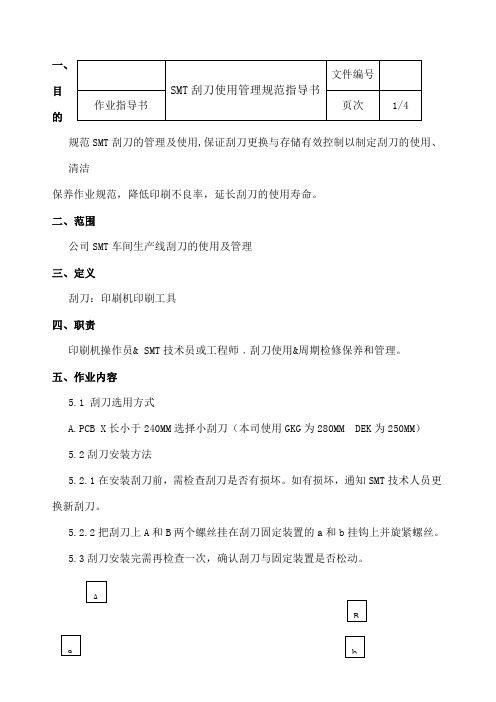
一、目的规范SMT 刮刀的管理及使用,保证刮刀更换与存储有效控制以制定刮刀的使用、清洁保养作业规范,降低印刷不良率,延长刮刀的使用寿命。
二、范围公司SMT 车间生产线刮刀的使用及管理三、定义刮刀:印刷机印刷工具四、职责印刷机操作员& SMT 技术员或工程师﹐刮刀使用&周期检修保养和管理。
五、作业内容5.1 刮刀选用方式A.PCB X 长小于240MM 选择小刮刀(本司使用GKG 为280MM DEK 为250MM )5.2刮刀安装方法5.2.1在安装刮刀前,需检查刮刀是否有损坏。
如有损坏,通知SMT 技术人员更换新刮刀。
5.2.2把刮刀上A 和B 两个螺丝挂在刮刀固定装置的a 和b 挂钩上并旋紧螺丝。
5.3刮刀安装完需再检查一次,确认刮刀与固定装置是否松动。
SMT 刮刀使用管理规范指导书文件编号 作业指导书 页次 1/4ABa b5.4操作员按生产需要,要将换下的刮刀用碎布或钢网纸沾酒精清洗干净,检查是否有损坏,坏刮刀通知SMT 技术员处理并及时更换新刮刀。
5.5操作员每天交班时需检查刮刀是否有损坏,如有损坏通知SMT 技术处理并及时更换新刮刀。
六、刮刀日点检6.1外观:看刀片锋口有无缺口,若有缺口须更换。
6.2刀片形状:看有无变形,平整度如何,若有扭曲变形须更换。
6.3刮刀硬度:太硬伤钢板,太软刮不干净,可通过印刷判断,在钢网和设备参数无误的状况下试印刷看钢网上面是否干净,若有锡膏糊在钢网上说明刮刀硬度太小。
6.4印刷过程中,锡膏的滚动会使部分锡膏进入刮刀的缝隙中,进入缝隙的锡膏如果没有及时的清除时间长了锡膏变干就会形成锡膏硬块,须将刮刀卸下清洗锡膏硬块,清洗干净刮刀部件后重新装好刮刀,要求设备操作人员每次清洗钢网时将刮刀清洗干净。
6.5钢刮刀片的使用寿命定为20万次印刷次数,要求进行保养,确认刮刀的性能。
生产中技术人员要随时关注印刷状况,如果印刷效果突然变差,或者钢板上局部或某些位置印刷后残留较多锡膏,可能刮刀片损伤或疲劳,需要更换刀片。
DEK印刷机基本操作

Fuba Automotive Electronics GmbH Confidential
•
(2)将钢网标签朝外放入机器里推到底,然后机器界面上的点击“安装钢网”,将钢网安装到机器里。
•
(3)把搅拌好的锡膏用搅拌刀加在钢网工作区域前段,与印刷区域有15MM左右的间距。
•
(3)点击机器命令窗口中的调用按钮,程序调用完成
Fuba Automotive Electronics GmbH Confidential
•
(4)程序调用完成后,按返回按键退出,回到主画面,设备刮刀臂会自动移动到产品设定的原点
• 2 .安装刮刀
• (1)将前后刮刀安装到机器上去。
后刮刀
前刮刀
• 3.安装钢网和添加锡膏
•(6)紧急停住按钮: 作用:在紧急事情情况下切断机器正常工作。
•(7)机器照明灯: 作用:点亮用来观察机器内部情况。
2
Fuba Automotive Electronics GmbH Confidential
Fuba Automotive Electronics GmbH Confidential
• 操作界面
Fuba Automotive Electronics GmbH Confidential
• 设备操作
• 1.调用程序
• (1)对应准备生产的产品,选用需要对应的产品名称程序,在主画面下,选择机器命令窗口里面2)选用对应的程序名称,如程序列表中没有找到程序,通知技术员或工程师设定
DEK印刷机的操作及注意事项
1
Fuba Automotive Electronics GmbH Confidential
DEK印刷机操作指导书
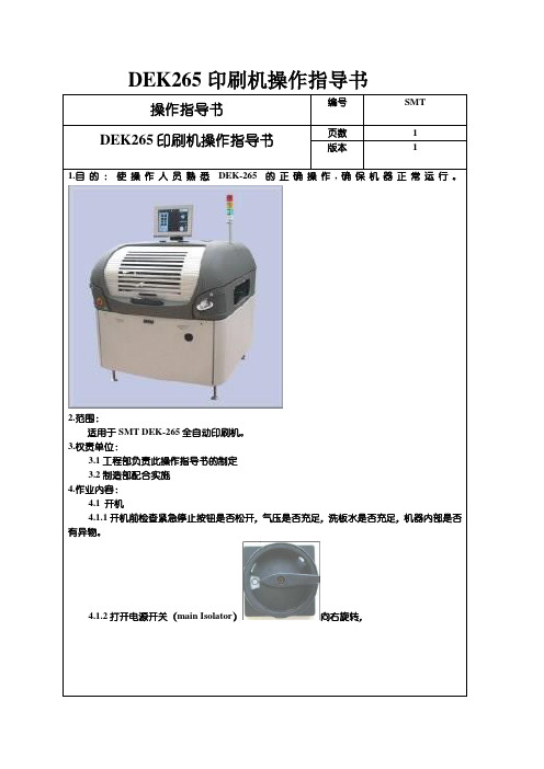
DEK265印刷机操作指导书操作指导书编号SMT DEK265印刷机操作指导书页数 1版本 11.目的:使操作人员熟悉DEK-265的正确操作,确保机器正常运行。
2.范围:适用于SMT DEK-265全自动印刷机。
3.权责单位:3.1工程部负责此操作指导书的制定3.2制造部配合实施4.作业内容:4.1 开机4.1.1开机前检查紧急停止按钮是否松开,气压是否充足,洗板水是否充足,机器内部是否有异物。
4.1.2打开电源开关(main Isolator)向右旋转,DEK印刷机操作指导书页数 2版本 1按下系统键系统进入初始化DEK265印刷机操作指导书页数 3版本 14.2初始化完毕后进入操作界面4.4生产程式的检查:4.4.1按下键,检查当前文件的名称以及数据,进入印刷参数的设定检查参数是否正确DEK265印刷机操作指导书页数 4版本 14.4.2应检查的参数产品名称基板长度基板宽度基板高度:前刮刀压力:后刮刀压力:前、后刮刀速度脱模速度:离网距离:基板基准点1X:MARK1的坐标基板基准点1Y:输入MARK1的Y 坐标基板基准点2X:输入MARK2的X坐标基板基准点2Y:输入MARK2的Y坐标清洁模式清洁速度丝网板开孔图案位置:4.4.3检查无误后,按键返回4.4.4.如文件名称与机种不符应重新调用程序,点击后进入界面选择相应的程序,并调用。
5.1安装钢网5.1.1放入钢网(注意网板方向要与PCB板的进板方向相符),并使用右手边夹杆上的刻度尺将钢网送至正确位置,回到界面后按键安装丝网。
每关上前盖都要按下系统键才能回到界面。
5.2刮刀的使用:刮刀在选择是要选用比PCB大50mm,刮刀与印框之间至少有80mm的距离。
操作指导书编号SMT DEK265印刷机操作指导书页数 5版本 15.2.1每次换线时需及时检查刮刀有无变形;将刮刀放置于链条轨道上,检查刮刀与链条轨道是否平贴5.2.2刮刀安装时要特别注意方向(前刮刀)(后刮刀),双手顺时针同时拧紧螺丝,拆卸方法与安装反向即可,拆卸完毕要清除干净残留的锡膏5.3添加锡膏5.3.1锡膏的初次使用量一般按PCB的尺寸来估计,(添加时要注意锡膏要保持在印刷钢网的与刮刀之间的非开口区域内,以免使PCB板弄脏)。
DEK操作手册
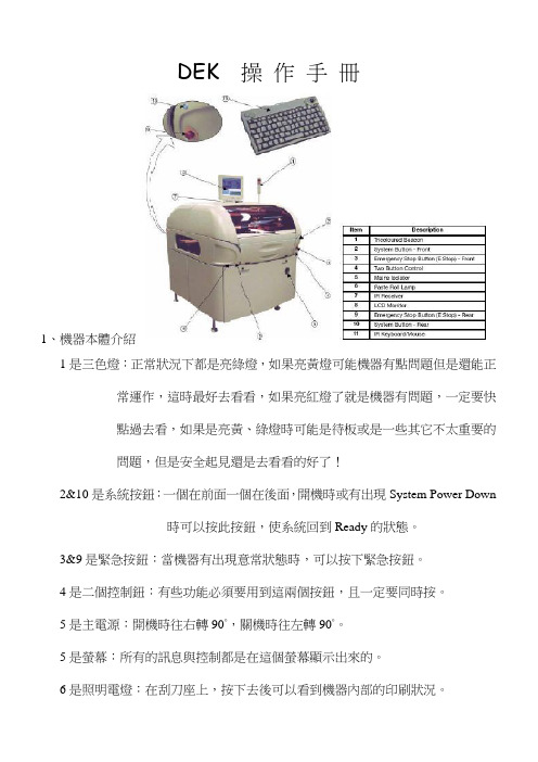
DEK 操作手冊1、機器本體介紹1是三色燈:正常狀況下都是亮綠燈,如果亮黃燈可能機器有點問題但是還能正常運作,這時最好去看看,如果亮紅燈了就是機器有問題,一定要快點過去看,如果是亮黃、綠燈時可能是待板或是一些其它不太重要的問題,但是安全起見還是去看看的好了!2&10是系統按鈕:一個在前面一個在後面,開機時或有出現System Power Down時可以按此按鈕,使系統回到Ready的狀態。
3&9是緊急按鈕:當機器有出現意常狀態時,可以按下緊急按鈕。
4是二個控制鈕:有些功能必須要用到這兩個按鈕,且一定要同時按。
5是主電源:開機時往右轉90°,關機時往左轉90°。
5是螢幕:所有的訊息與控制都是在這個螢幕顯示出來的。
6是照明電燈:在刮刀座上,按下去後可以看到機器內部的印刷狀況。
7是IR紅外線接收器:接收鍵盤&滑鼠的裝置。
8是LCD螢幕:所有的訊息與控制都是在這個螢幕顯示出來的。
11是鍵盤&滑鼠:紅外線的鍵盤&滑鼠,選擇功能時用!下面為機器的尺寸圖與規格圖2、有兩種顯示方式,在下面分別介紹一下1是顯示日期、年、機器名稱、機器編號、時間。
2是印刷機的參數視窗。
3是訊息視窗。
4是主選單。
5是影像是也就是照相機所照出來的情況。
6是警告訊息視窗。
7是印刷機機器本體的狀態視窗。
這是第二種顯示方式,也是較常看到的1是印刷機的參數視窗。
2是印刷機的參數視窗。
3是訊息視窗。
4是主選單。
5是影像是也就是照相機所照出來的情況。
6是警告訊息視窗。
7是印刷機機器本體的狀態視窗。
8是顯示日期、年、機器名稱、機器編號、時間。
3、打開機器的主電源,讓電腦運作,直到開起DEK的畫面。
當看到畫面會問你Press SYSTEM Switch To Initialize Printer or Select Diagnosticsor Load Data若直接按System鍵會進入上次開機時的程式,若按Load Data(F2)會請你選擇一個程式,然後再按System鍵,當你按下System鍵時,機器會做歸零動作,請先確定軌道上無PCB,下無頂Pin,否則會有錯誤訊息出現。
DEK印刷机操作指引
DEK印刷机操作指引DEK印刷机是一种高度自动化的印刷设备,广泛应用于电子组装行业。
本文将为您介绍DEK印刷机的操作指引,让您能够熟练操作和调整该设备,提高印刷质量。
1. 印刷机的基本组成部分DEK印刷机由以下几个主要组成部分组成:•框架:印刷机的基本结构,提供支撑和稳定性。
•胶刮刀:用于将胶浆均匀刮涂到PCB(Printed Circuit Board)上。
•打印头:控制胶浆的喷涂和喷射。
•输送系统:将PCB从一个位置传送到另一个位置。
•控制系统:用于控制印刷机各部分的运行和协调。
2. 准备工作在操作DEK印刷机之前,需要进行以下准备工作:2.1 检查设备状态•确保印刷机的电源和气源正常供应。
•检查印刷机各部分的状态,确保无异常情况。
•检查印刷机的刮刀和打印头是否干净,并进行必要的清洁。
2.2 根据需求设置参数•根据需要,设置印刷机的工作模式,如自动模式或手动模式。
•根据PCB的尺寸和要求,调整输送系统。
•根据胶浆的特性和粘度,调整胶刮刀和打印头的参数。
2.3 准备待印刷的PCB•检查待印刷的PCB,确保其尺寸和其它物理特性符合要求。
•清洁待印刷的PCB,确保其表面干净。
3. 操作步骤以下是DEK印刷机的基本操作步骤:3.1 打开印刷机•打开印刷机的电源开关,并确保设备正常启动。
•操作控制系统,选择合适的工作模式。
3.2 调整输送系统•根据PCB的尺寸,调整输送系统,确保PCB能够平稳地传送。
•确保输送系统的角度和速度合适,以避免PCB的移位和变形。
3.3 调整胶刮刀和打印头•使用调节装置,调整胶刮刀的高度和角度,确保胶浆能够均匀地刮涂到PCB上。
•调整打印头的位置和角度,确保胶浆能够准确地喷涂到特定区域。
3.4 检查胶浆•检查胶浆的粘度,如果需要,可以进行必要的稀释或加热处理。
•确保胶浆的质量符合要求,避免造成印刷质量问题。
3.5 进行印刷•将待印刷的PCB放置在输送系统上,并启动印刷过程。
DEK全自动印刷机操作指导书
表單編號:KQR0-0002A1 流程圖1 目的便于正确操作.维护设备机器,保证印刷品质,提高生产效率。
2 范围从事DEK-HORIZON 03IX全自动印刷机操作的作业人员。
3 权责操作员对印刷机操作.保养及维护,技术员及工程师负责对机器调校,品质部对制程进行跟踪。
4 内容1.设备概要:2.界面介绍:3.通电启动:3.1打开机器右下方总电源开关,顺时针旋转90度,电脑开始启动。
3. 2当提示启动完成,脑屏幕显示DEK画面,按下系统键进行初始化机器,然后出现主菜单。
4.作业前的准备:1.1确认待印刷PCB与BOM是否相符,与钢网是否对应。
1.2确认锡膏(胶水)是否已回温及搅拌OK。
1.3确认技术人员是否调好程式及架好钢网。
1.4确认钢网是否已按工艺要求封好孔。
1.5戴上静电环及静电手套。
5.更换程序:5.1点(更换产品)键,将光标移动到生产程序上。
5.2选择要生产的程序,点确认键,设备运行程序参数。
5.3安装PCB支撑柱并进行钢网安装,校正基准点进行对位。
加入适量锡膏(胶水)在钢网上。
5.4制令批量设置,根据技术人员指导,按正确方向放PCB入导轨。
进行印刷。
5.5机器印刷完毕后,从板边拿起PCB,勿接触印刷点及金手指部位。
至放大镜下检查是否有连锡.漏印.拉锡.塌印等不良。
5.6将检查OK的PCB转让下一工序,不良品单独放置,待统一清洗。
5 注意事项1.每半小时用搅拌刀将印刷区域外的锡膏收至印刷区内。
保持印刷区域外清洁避免锡膏污染。
2.自动擦拭钢网1-20片一次根据PCB板性质不一,频率不一。
可针对性选择干擦.湿擦.真空擦。
3.及时查看耗材(擦拭纸.清洁液)使用状况。
提前准备更换动作。
避免造成品质及效率异常。
- 1、下载文档前请自行甄别文档内容的完整性,平台不提供额外的编辑、内容补充、找答案等附加服务。
- 2、"仅部分预览"的文档,不可在线预览部分如存在完整性等问题,可反馈申请退款(可完整预览的文档不适用该条件!)。
- 3、如文档侵犯您的权益,请联系客服反馈,我们会尽快为您处理(人工客服工作时间:9:00-18:30)。
CHAPTER 9 SQUEEGEE MODULEOVERVIEWItem Description Item Description1Squeegee Printhead Mechanism5Squeegee Drip Tray2Rear Squeegee Stepper Motor6Rear Squeegee3Front Squeegee7Print Carriage4Squeegee Drip Tray Mechanism8Front Squeegee Stepper MotorChapter Issue 1 Jan 07Technical Reference Manual9.1The squeegee mechanism is driven backwards and forwards across the screenby the print carriage.The squeegee printhead mechanism incorporates two stepper motors to drivethe two squeegees independently down onto the screen when a print stroke isrequired. During the rearward stroke, the front squeegee is in contact with thescreen performing a rear print stroke. During the forward stroke, the rearsqueegee is in contact with the screen performing a forward print stroke.The pressure being applied during the print stroke is measured by a straingauge bridge (located in the spring beam assembly of the squeegee mecha-nism) and if necessary, a correction to the pressure is made by the software.Figure 9-1 Squeegee Sensor Locations9.2Technical Reference Manual Chapter Issue 1 Jan 07Chapter Issue 1 Jan 07Technical Reference Manual 9.3Squeegee Drip TrayFigure 9-2 Squeegee Drip Tray OverviewThe squeegee drip tray mechanism secures to the underneath of the print carriage. The drip tray pneumatic actuator extends the drip tray below the squeegees to prevent print medium from dripping onto the screen during print carriage initialisation or auto screen loading.The squeegee drip tray mechanism is also used to accommodate the auto screen loader mechanism, refer to the Adjustable Screen Mount (ASM) or Cast C Chase Module chapters for more information.The drip tray retracted sensor is used by software to check that the pneumatic actuator has retracted the drip tray before lowering the squeegees.NOTEWith the squeegee drip tray and the screen depth adjuster fitted, the ASM must be set to 29 inches and cannot accommodate smaller screen sizes.ELECTRICAL SCHEMATIC9.4Technical Reference Manual Chapter Issue 1 Jan 07Chapter Issue 1 Jan 07Technical Reference Manual 9.5REPLACEMENT PROCEDURES ProFlow to SqueegeesInstances may occur when the machine is required to print using the squeegee module configuration. The following procedure details how to revert the machine from ProFlow use to the squeegee configuration:Removing ProFlow 1.Select.2.SelectDiagnostics .e Next or Previous to highlight ProFlow .4.Select Select Module .5.Ensure Home ProFlow is highlighted.6.Select Run Diagnost .7.Select Exit .8.Select Exit .9.SelectBack .10..11.Select.12.SelectBack .13.SelectShut Down and switch the mains isolator to OFF .14.Disconnect both curly air lines from the self-seal pneumatic connectorssituated either side of the ProFlow printhead mechanism.15.Disconnect the three ProFlow mechanism connectors from the print car-riage, left hand side:•ProFlow Motor•Home Sensor•ProFlow Paste Level Sensor (if Time to Go is enabled, an amplifier isconnected to 9PL61 and the connection is made to 9PL62 on the ampli-fier).16.Manually raise the ProFlow pressure mechanism by pulling the latch on thefront of the unit and lifting the mechanism to the fixed raised position.17.Open the locking clip securing the transfer head to the pressure mechanismand carefully slide the transfer head out and away from the pressuremechanism as indicated in the figure below.9.6Technical Reference Manual Chapter Issue 1 Jan 0718.Release the pressure mechanism from the printhead mechanism byunscrewing the two securing bolts, using a 5mm Allen key.19.Loosen the four captive screws securing the ProFlow printhead mechanismto the print carriage using a 4mm Allen key. Carefully remove the mecha-nism from the print carriage.Chapter Issue 1 Jan 07Technical Reference Manual9.7Fitting Drip Tray 1.Slide the slot in the drip tray onto the bearing on the drip tray guide shaft.2.Secure the drip tray to the actuator piston using the securing screw.3.Open the speed control valves on the drip tray actuator.Fitting Squeegee 1.Carefully position the rear of the printhead mechanism (spring beamassembly) into the print carriage so that both printhead mechanism dowelslocate into the print carriage locating holes. Secure the unit to the printcarriage by means of the four captive screws, ensuring the pneumatic pipeis not trapped.9.8Technical Reference Manual Chapter Issue 1 Jan 07Chapter Issue 1 Jan 07Technical Reference Manual 9.92.Connect the following connectors to the print carriage, left hand side:•Rear Squeegee Motor •Front Squeegee Motor •Home Sensors•Squeegee Pressure Amplifier3.Fit the required configuration of squeegees to the printhead mechanismsqueegee mounts.NOTESqueegee fitting information is detailed in the Replacement Procedures section of this chapter.4.Switch the mains isolator to ON and ensure that the machine recognizes thesqueegee module fit by displaying Squeegees Uninitialised during theDrive Belt Replacement1..2.Select.3.SelectBack .4.SelectShut Down.9.10Technical Reference ManualChapter Issue 1 Jan 075.SelectContinue .6.Switch the mains isolator to OFF .7.Open the front printhead cover/shutter.8.Remove squeegees if fitted.9.Remove the drive belt cover plate from the squeegee printhead mechanismand remove the broken drive belt.Rear Squeegee Drive Belt3.Fit the new belt in position.ing a cable tie wrap or similar, provide a loop around the top of the bodyof the motor enabling the motor to be pulled using a force meter. Ensure that the force meter is pulled in the direction which the drive belt is fitted,figure above refers.5.Pull the force meter until a tension of 3-4kgs is monitored on the meter.Tighten the three screws whilst the motor is under tension.Front Squeegee Drive Belt 1.To replace the front squeegee drive belt (left hand stepper motor), theprinthead mechanism must be removed from the print carriage.2.Disconnect the following connectors from the print carriage, left hand side(figure in Step 10 of ProFlow to Squeegees section refers):•Rear Squeegee Motor•Front Squeegee Motor•Home Sensors•Squeegee Pressure Amplifier3.Remove the printhead mechanism by unscrewing the four screws securingthe unit to the print carriage.4.Placing the unit on a secure surface, slacken off the three screws securingthe left hand motor to the support plate.5.Fit the new belt in position.ing a cable tie wrap or similar, provide a loop around the top of the bodyof the motor enabling the motor to be pulled using a force meter. Ensure that the force meter is pulled in the direction which the drive belt is fitted, Rear Squeegee Motor Tensioning figure example refers.7.Pull the force meter until a tension of 3-4kgs is monitored on the meter.Tighten the three screws whilst the motor is under tension.8.On completion re-fit the printhead mechanism to the print carriage refit thedrive belt cover plate and re-connect all leads to the print carriage, left hand side.9.Refit the squeegees.Fitting the Squeegees It is usual to fit two trailing edge squeegees and use the machine in the Print/ Print mode.When fitting a single squeegee (trailing edge or diamond section) to the machine, it must be fitted to the front squeegee mount only.The following procedure describes a double trailing edge squeegee configura-tion fit to the machine printhead mounting assembly.1.Select Product Setup.2.Select Change Squeegees.3.The print carriage is driven to the front position.Item Description Item Description1Front Squeegee Mount5Front Squeegee2Rear Squeegee Mount6Front Squeegee Key and Keyway Slot 3Locking Thumbscrew (in 4 positions)7Rear Squeegee Key and Keyway Slot 4Rear Squeegee6.Fit the front squeegee to the front squeegee mount ensuring the thumb-screws are tightened finger tight.NOTEThe locking thumbscrews on the front squeegee are positioned closer together than those fitted to the rear squeegee and the keyway slot is positioned on the right hand side of the front squeegee.7.Close the front printhead cover/shutter.8.Press the System button.9.SelectContinue .10.SelectBack .11.Carry out Squeegee Reference Height calibration, Calibrations section ofthis chapter refers.CALIBRATIONSSqueegee Pressure Calibration Squeegee pressure calibration is carried out on machines, fitted with the Pressure Hardware option, after the following circumstances:•The squeegee mechanism is replaced•The strain gauge bridge in the squeegee mechanism is replaced•The rising table sensors have been replaced or adjustedA force meter calibration jig and squeegee pressure plate are required to perform the squeegee pressure calibration.NOTE1.Ensure that the rising table print reference height is set correctly beforecommencing, (the calibration relies upon accurate positioning of the table to make a reference).2.Ensure that the Pressure Hardware parameter in Maintenance\MachineSetup\Options is set to FITTED.Use the following procedure to calibrate the squeegee pressure:WARNINGBOARD CLAMPS. EXTREME CARE MUST BE EXERCISED WHEN WORKING IN THE TOOLING AREA OF THE MACHINE TO AVOID INJURY. THE FOILS ON THE FRONT AND REAR BOARD CLAMPS ARE VERY SHARP.1..2.Select.3.Select Unload Screen.4.Open the front printhead cover/shutter.5.Remove the screen from the machine.6.Remove the tooling from the manual tooling plate.7.Close the front printhead cover/shutter.8.Press the System button.9.Select Back.10.Select.11.Select.12.Select Pressure .13.Select Calibrat Readings .The rails are checked for the presence of a board, the print carriage moves to the calibration position, the rear rail moves to home position, the table homes and the board clamps are closed.14.The machine cover is unlocked and the message ‘Fit the pressure calibra-tion rig’ is displayed with the following window:15.Open the front printhead cover/shutter.16.Ensure that the calibration jig is secured to the mounting plate as shown inthe following graphic:17.Fit the calibration jig to the front squeegee position.18. Fit the squeegee pressure plate to the rising table ensuring that the locatingdowels insert the holes of the rising table.NOTEDuring the squeegee pressure calibration the dwell height of the rear squeegee is 15mm regardless of the set up value. This height is set during calibration only.19.Switch the force meter ON and check the reading is 0kg, (ensure the forcemeter is not in contact with the squeegee pressure plate).20.Select Continue.21.The front squeegee mechanism steps down until a change in pressure isdetected and continues stepping down until the pressure value stored on the machine is reached. If the calibration jig displays 10kg, go to Step 25.22.Select Jog Rig.e the left and right jog buttons to move the front squeegee mechanism upor down until the calibration jig displays 10kg.NOTEAchieving exactly 10kg may not be possible as some calibration jigs display down to three decimal places.24.Select Set Calib..25.Select Exit.26.The front squeegee mechanism moves to the home position. The message‘Confirm that the pressure calibration jig has been removed.’ is dis-played.27.Remove the calibration jig and the squeegee pressure plate from themachine. On completion select Yes, the table resets, the print carriage moves to home position, board clamps open and the rear rail moves to the board width setting.28.Carry out the Squeegee Reference Height (Pressure Feedback) calibration.Squeegee Reference Height (Pressure Feedback)Squeegee reference height is carried out on machines fitted with the Pressure Hardware option after the following circumstances:•Squeegee pressure calibration•Squeegee changeUse the following procedure to set the squeegee reference height:1.If a Ptest.dat file is not required, go to Step 7.2.Select.3.Select Test Cycles.4.Select Data Logging On.5.Select Back.6.Select Back.7.Select Setup Product.8.SelectSqueegees.9.Select Unload Screen.10.Open the front printhead cover/shutter.11.Remove the screen from the machine.12.Close the front printhead cover/shutter.13.Press the System button.14.Select.15.The message ‘Ensure that the correct squeegees are fitted!’ is dis-played.16.Fit the required squeegees to the front and rear squeegee mounts asdetailed in the Replacement Procedures section of this chapter.17.SelectContinue .18.The following machine sequence is carried out:a.The rails are checked for the presence of a board.b.The rising table is driven to print height.c.The board clamps are closed.d.The print carriage drives the front squeegee over the front rail.e.The rear squeegee is driven down to dwell height.f.The front squeegee is driven down by the stepper motor until contact with the board clamp is made.g.The front squeegee continues to be driven down until a 2kg pressure difference is detected, the motor pauses.h.The amount of steps (the stepper motor took to get to this position) and the pressure are recorded.i.The stepper motor drives downwards another 15 steps, this is recorded with the pressure detected. This is repeated a further 18 times to achieve a total of 20 results.19.The rear squeegee is calibrated in a similar manner.20.The message ‘Calibrate Squeegee heights complete’ is displayed.21.SelectBack .22.SelectBack .23.Select.24.SelectTest Cycles .25.SelectData Logging Off .26.SelectBack .27.SelectBack .Ptest.dat FileThe file displays 20 front squeegee readings followed by 20 rear squeegee readings, showing the relationship between steps (displacement) and pressure applied. From the readings taken, the front and rear pressure factors and squeegee reference heights are calculated. At the end of the file, 5 readings of flood pressure and reference height readings are displayed (these are also listed in the Config.txt file).The Ptest.dat file is located on the hard drive of the machine PC. To view the file carry out the following procedure:1.From the Windows start menu, select Programs - Accessories - WindowsExplorer .2.Under My Computer , locate and open the E:\Log\Ptest.dat file.The figure below gives a representation of the Ptest.dat file.Squeegee Reference Height (Non Pressure Feedback)The squeegee reference height is carried out after a squeegee change on machines without the Pressure Hardware option. This procedure must be used if Pressure Hardware is disabled.Use the following procedure to set the squeegee reference height:1..2.Select.3.Select Unload Screen.4.Open the front printhead cover/shutter.Chapter Issue 1 Jan 07Technical Reference Manual 9.215.Remove the screen from the machine.6.Fit the required squeegees to the front and rear squeegee mounts asdetailed in the Replacement Procedures section of this chapter.7.Close the front printhead cover/shutter.8.Press the System button.9.SelectBack .10.SelectSetup Product .11.SelectSqueegees .12.Select.13.The following machine sequence is carried out:a.The rails are checked for the presence of a board.b.The rising table is driven to print height.c.The board clamps are closed.d.The print carriage drives the front squeegee over the front rail.e.The front and rear squeegees are driven down by the stepper motor to dwell height.14.Select Calibrate Front Squeegee .15.The front squeegee is driven down to the current reference height position.16.SelectJog .17.Open the front printhead cover/shutter.ing a 0.1mm shim placed between the front rail and the front squeegee,check that the shim moves with a small amount of friction.19.If the gap is correct, go to Step 29.20.For adjustment, select the appropriate Jog Up/Jog Down button on themonitor.9.22Technical Reference Manual Chapter Issue 1 Jan ing the two button controls simultaneously, jog the squeegee in thechosen direction.22.Recheck the gap.23.Repeat Steps 20 to 22 until the correct gap is achieved.24.Close the front printhead cover/shutter.25.Press the System button.26.SelectBack .27.SelectSave .28.Go to Step 31.29.Close the front printhead cover/shutter.30.Press the System button.31.SelectBack .32.Select Calibrate Rear Squeegee .33.The rear squeegee is driven down to the current reference height position.34.Repeat Steps 16 to 31 for the rear squeegee.35.SelectBack .36.SelectBack .37.SelectBack .。