【ROUTE-1】CCNP ROUTE EIGRP综合实验
CCNP路由实验专题讲解--OSPF篇配套测试题

CCNP路由实验专题讲解--OSPF篇配套测试题CCNP路由实验专题讲解--OSPF篇配套测试题1.【判断题】10分| 配置OSPF时,必须要使用相同的进程号A对B错2.【单选题】10分| 下列哪一项不是OSPF建立邻居关系的必要条件?A hello计时器一致B 区域一致C RID不同D 进程号一致3.【单选题】10分| 在思科产品上,OSPF路由协议的管理距离是多少?A 90B 100C 110D 1204.【判断题】10分| 配置接口的OSPF优先级为255,可以确保此路由器成为DRA对B错5.【单选题】10分| OSPF通过下列哪一条命令实现外部路由条目的汇总?A ip summary-addressB summary-addressC areaXrangeD areaXsummary-address6.【单选题】10分| 在默认配置下,1000M接口的OSPF的COST是多少?A 100B 10C 1D 0.57.【单选题】10分| 默认条件下,OSPF的外部路由条目在路由表中的类型为?A OB OIAC OE1D OE28.【单选题】10分| OSPF 类型7的LSA代表哪一个特殊区域产生的链路状态通告?A stubB totallystubC NSSAD area 09.【单选题】10分| OSPF的协议号是多少?A 6B 17C 88D 8910.【单选题】10分| 在OSPF协议配置模式中,下列哪一条命令是错误的?A Router(config-router)#distribute-list 1 in fa0/0B Router(config-router)#distribute-list 1 inC Router(config-router)#distribute-list 1 out eigrpD Router(config-router)#distribute-list 1 out fa0/0。
EIGRP实验配置过程详解
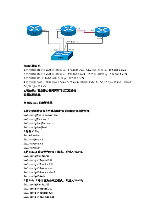
实验环境说明:1.将路由器R1的Fa0/0端口配置ip:172.16.0.1/24;S1/2端口配置ip:192.168.1.1/242.将路由器R2的Fa0/0端口配置ip:192.168.3.2/24;S1/2端口配置ip:192.168.1.2/243.将路由器R3 的Fa0/0端口配置ip:172.16.0.3/244.将交换机SW1分别划分两个VLAN2、VLAN3,将端口Fa1/13、Fa1/15划入VLAN2,将端口Fa1/14划入VLAN3实验结果:要求路由器间两两可以互相通信配置过程详解:交换机SW1的配置清单:1.首先禁用错误命令当域名解析和关闭超时退出控制台:SW1(config)#no ip domain-looSW1(config)#line con 0SW1(config-line)#no exec-tSW1(config-line)#exit2.划分VLAN:SW1#vlan dataSW1(vlan)#vlan 2SW1(vlan)#vlan 3SW1(vlan)#exit3.将Fa1/13端口设为全双工模式,并划入VLAN2:SW1(config)#int fa1/13SW1(config-if)#speed 100SW1(config-if)#duplex fullSW1(config-if)#sw mod accSW1(config-if)#sw acc vlan 2SW1(config-if)#exit4.将Fa1/15端口设为全双工模式,并划入VLAN2:SW1(config)#int fa1/15SW1(config-if)#speed 100SW1(config-if)#duplex fullSW1(config-if)#sw mod accSW1(config-if)#sw acc vlan 2SW1(config-if)#exit5.将Fa1/14端口设为全双工模式,并划入VLAN3:SW1(config)#int fa1/14SW1(config-if)#speed 100SW1(config-if)#duplex fullSW1(config-if)#sw mod accSW1(config-if)#sw acc vlan 3SW1(config-if)#exit路由器R1的配置清单:1.首先禁用错误命令当域名解析和禁用超时退出控制台:R1(config)#no ip domain-looR1(config)#line con 0R1(config-line)#no exec-tR1(config-line)#exit2.将Fa0/0端口设为全双工模式并配置ip:R1(config)#int fa0/0R1(config-if)#speed 100R1(config-if)#duplex fullR1(config-if)#ip add 172.16.0.1 255.255.255.0R1(config-if)#no shutR1(config-if)#exit3.为S1/2端口配置ip:R1(config)#int s1/2R1(config-if)#ip add 192.168.1.1 255.255.255.0R1(config-if)#no shutR1(config-if)#exit4.在路由器R1上配置EIGRP:R1(config)#router eigrp 100R1(config-router)#no auto-summaryR1(config-router)#network 172.16.0.1 0.0.0.0R1(config-router)#network 192.168.1.1 0.0.0.255R1(config-router)#exitR1(config)#exit路由器R2的配置清单:1.首先禁用错误命令当域名解析和禁用超时退出控制台:R2(config)#no ip domain-looR2(config)#line con 0R2(config-line)#no exec-tR2(config-line)#exit2.将Fa0/0端口设为全双工模式并配置ip:R2(config)#int fa0/0R2(config-if)#speed 100R2(config-if)#duplex fullR2(config-if)#ip add 192.168.3.2 255.255.255.0R2(config-if)#no shutR2(config-if)#exit3.为S1/2端口配置ip:R2(config)#int s1/2R2(config-if)#ip add 192.168.1.2 255.255.255.0R2(config-if)#no shutR2(config-if)#exit4.在路由器R2上配置EIGRP:R2(config)#router eigrp 100R2(config-router)#network 192.168.3.0 0.0.0.255R2(config-router)#network 192.168.1.0 0.0.0.255R2(config-router)#exitR2(config)#exit路由器R3的配置清单:1.首先禁用错误命令当域名解析和禁用超时退出控制台:R3(config)#no ip domain-looR3(config)#line con 0R3(config-line)#no exec-tR3(config-line)#exit2.将Fa0/0端口设为全双工模式并配置ip:R3(config)#int fa0/0R3(config-if)#speed 100R3(config-if)#duplex fullR3(config-if)#ip add 172.16.0.3 255.255.255.0R3(config-if)#no shutR3(config-if)#exit3.在路由器R3上配置EIGRP:R3(config)#router eigrp 100R3(config-router)#no auto-summaryR3(config-router)#network 172.16.0.3 0.0.0.0R3(config-router)#exitR3(config)#exit验证EIGRP配置:查看每台路由器的邻居表:#show ip eigrp neiR1的邻居表:R1#show ip eigrp neiIP-EIGRP neighbors for process 100H Address Interface Hold Uptime SRTT RTO Q Seq(sec) (ms) Cnt Num1 172.16.0.3 Fa0/0 11 00:00:48 168 1008 0 40 192.168.1.2 Se1/2 14 00:25:23 244 1464 0 3R2的邻居表:R2#show ip eigrp neiIP-EIGRP neighbors for process 100H Address Interface Hold Uptime SRTT RTO Q Seq(sec) (ms) Cnt Num0 192.168.1.1 Se1/2 14 00:28:34 195 1755 0 5R3的邻居表:R3r#show ip eigrp neiIP-EIGRP neighbors for process 100H Address Interface Hold Uptime SRTT RTO Q Seq(sec) (ms) Cnt Num0 172.16.0.1 Fa0/0 12 00:02:07 134 804 0 8实验的最终结果是每台路由器之间都可以ping通其他的路由器,实验过程到此结束。
CCNP实验GRE隧道流量的IPSEC加密概况

CCNP实验GRE隧道流量的IPSEC加密由于IPSEC只支持对单播流量的加密,所以我们使用GRE隧道可以将广播、组播包封装在一个单播包中,再用IPSEC进行加密。
在进行IPSEC配置前应首先配置好GRE隧道,下面是R1上的GRE隧道配置:R1:interface tunnel0 ip address 192.168.3.1 255.255.255.0tunnel source s1/1tunnel destination 192.1.1.20exit interface s1/1 ip address 192.1.1.40 255.255.255.0ip access-group perimeter inexit interface lo0 ip address 192.168.1.1 255.255.255.0exit ip route 0.0.0.0 0.0.0.0 192.1.1.20!在这里我将总公司内部的骨干网络设为Area0,隧道部分和分公司内部网络设为Area1 (二)寒邪特性及致病特征ospf 1②寒性凝滞,易致疼痛 network 192.168.3.0 0.0.0.255 area 1exit(三)暑邪特性及致病特征①暑性炎热,易致发热②暑性升散,耗气伤津③暑多挟湿,易困脾胃(四)湿邪特性及致病特征①湿郁气机,易损脾阳②湿性重浊,其性趋下③湿性粘滞,缠绵难退ip(五)燥邪特性及致病特征(六)火 permit udp host 192.1.1.20 host 192.1.1.40①火为热极,其性炎上,permit esp③火邪易伤津液gre host 193.1.1.20 host 192.1.1.40内伤主要由于饲养管理不当引起,概括为饥、饱、劳、役四种。
ip三、其他致病因素四、病机(一)邪正消长(二)升降失常(三)阴阳失调第六章四诊(望、闻、问、切)(一)察口色的部位(二)口色1、舌诊所应舌色应心,唇色应脾,金关应肝,玉户应肺,排齿应肾,口角应三焦2、口色分类正色、病色、绝色R2:(1)白色:主虚证,为气血不足之征兆(2)赤色:赤色主热,为气血趋向于外的反应(3)青色:青色主寒、主痛、主风,为感受寒邪及疼痛的象征interface tunnel0ip3tunnel source s1/01)白苔:主表证和寒证,临床最常见(2)黄苔:主热证和里证,淡黄色为微热,深黄为热重ip)灰黑苔:主热、寒湿或虚寒证,表示湿浊重,病情危重ip(一)切脉的部位 access-group perimeter in、马切颌外动脉或颈总动脉2、牛切尾中动脉或颈总动脉、猪、羊切股内动脉1、平脉:正常脉象。
思科基础实验(中英文对照)CCNA-CCNP实验

目录实验一路由器基本配置............................................ 错误!未指定书签。
实验二静态路由......................................................... 错误!未指定书签。
实验三缺省路由......................................................... 错误!未指定书签。
实验四静态路由&缺省路由&CDP协议............... 错误!未指定书签。
实验五三层交换机实现VLAN间通信................. 错误!未指定书签。
实验六Vtp ................................................................... 错误!未指定书签。
实验七生成树STP ..................................................... 错误!未指定书签。
实验八RIP路由协议1 ............................................. 错误!未指定书签。
实验九RIP路由协议2 ............................................. 错误!未指定书签。
实验十OSPF单区域1 .............................................. 错误!未指定书签。
实验十一OSPF单区域2 ......................................... 错误!未指定书签。
实验十二OSPF单区域3 ......................................... 错误!未指定书签。
实验十三EIGRP ........................................................ 错误!未指定书签。
CCNPv6_ROUTE_Lab2-6_EIGRP_Challenge_Instructor

Note: To find out how the router is configured, look at the interfaces to identify the type of router and how many interfaces the router has. Rather than list all combinations of configurations for each router class, this table includes identifiers for the possible combinations of Ethernet and serial interfaces in the device. The table does not include any other type of interface, even though a specific router might contain one. For example, for an ISDN BRI interface, the string in parenthesis is the legal abbreviation that can be used in Cisco IOS commands to represent the interface.
As you work through the challenge steps, you can document commands used and ideas for satisfying the requirements specified in the Notes section below. Notes: ______________________________________________________________________________ ____________________________________________________________________________________ ____________________________________________________________________________________ ____________________________________________________________________________________ ____________________________________________________________________________________ ____________________________________________________________________________________ ____________________________________________________________________________________ ____________________________________________________________________________________ ____________________________________________________________________________________ ____________________________________________________________________________________ ____________________________________________________________________________________ ____________________________________________________________________________________ ____________________________________________________________________________________ ____________________________________________________________________________________ ____________________________________________________________________________________ ____________________________________________________________________________________ ____________________________________________________________________________________ ____________________________________________________________________________________ ____________________________________________________________________________________ ____________________________________________________________________________________ ____________________________________________________________________________________ ____________________________________________________________________________________ ____________________________________________________________________________________ ____________________________________________________________________________________ ____________________________________________________________________________________ ____________________________________________________________________________________ ____________________________________________________________________________________ ____________________________________________________________________________________
EIGRP实验

D10.0.0ቤተ መጻሕፍቲ ባይዱ0/8 [90/2297856] via 172.16.1.1, 00:10:10, Serial1/0
D 192.168.0.0/24 [90/2297856] via 172.16.1.6, 00:08:14, Serial1/1
R1(config-router)#exit
R1(config)#
随后在R2上观察路由表的变化,如下显示:
R2#show ip route eigrp
172.16.0.0/16 is variably subnetted, 3 subnets, 2 masks
D 172.16.0.0/16 is a summary, 00:07:26, Null0
Sending 5, 100-byte ICMP Echos to 192.168.1.1, timeout is 2 seconds:
.!!!!
Success rate is 80 percent (4/5), round-trip min/avg/max = 4/43/92 ms
R2#
6、路由器R2作为企业的出口路由器,由于其配置了静态路由,因此其可以直接访问外部,但是内部的R1和R5路由器由于缺少路由,因此无法访问外网。下面显示了R1路由器的路由表和其向外部发起ping的访问结果:
R2#
7、我们注意到在R2路由器上有一条指向s1/0口的10.0.0.0/8的汇总路由,这是EIGRP路由协议自动汇总的特性体现。可以使用no auto-summary命令关闭。如下:
R1(config)
eigrp配置的综合实训
eigrp配置的综合实训
EIGRP(Enhanced Interior Gateway Routing Protocol)是一个用于IP网络的动态路由协议,可以帮助网络管理员轻松管理和配置路由。
以下是EIGRP配置综合实训的步骤:
1. 配置基本网络设置:
- 配置主机IP地址和子网掩码。
- 配置路由器的主机名。
2. 启用EIGRP协议:
- 在路由器上启用EIGRP进程。
- 配置EIGRP AS号码(Autonomous System)。
3. 配置EIGRP邻居关系:
- 配置路由器之间的邻居关系。
- 使用neighbor指令指定邻居路由器的IP地址。
4. 配置EIGRP网络:
- 使用network指令配置使用EIGRP协议的网络。
- 确保所有需要使用EIGRP协议的网络都被包含在内。
5. 配置EIGRP路由策略:
- 配置路由器的EIGRP路由策略。
- 使用路由地图(Route Map)来控制通告的路由。
6. 验证EIGRP配置:
- 使用show命令验证EIGRP邻居关系是否建立。
- 使用show ip route命令验证路由表中是否包含正确的EIGRP路由。
7. 测试EIGRP实时性和容错性:
- 运行traceroute命令验证EIGRP路由。
- 模拟故障,并观察EIGRP协议重新计算路由的能力。
在进行综合实训之前,建议提前了解EIGRP协议的基本概念和相关配置命令。
另外,确保使用网络仿真工具(如Packet Tracer)或实际物理设备进行实验,以便实际操作和验证配置的效果。
CCNP考试心得
CCNP 考试总结及心得体会紧张而又刺激的cisco 认证CCNP(Route and Switch)考证终于宣告一段落,总共用时六个月,以下是我的三门的考试成绩:CCNP ROUTE (642-902)——815 分CCNP SWITCH (642-813)——934 分CCNP TSHOOT (642-832)——1000 分总的来说,CCNP 的考试还是比较简单的,当然题量略多,尤其是路由部分,主要是考验一个人的耐心、毅力!所谓贵在坚持,我记得有人曾经说过这样一句话:“人不去逼自己,永远不知道自己有多强大!”。
话不多说,接下来介绍一下我考NP 的一些心得和方法,仅供参考(*^__^*) 嘻嘻,, 首先是CCNP ROUTE (642-902)路由部分:1> 个人认为路由部分是最简单的,虽说我考的分数是最低的,但是考过的人都知道,路由虽说题库给的题量很多,背起来非常辛苦,很累。
但是,考试的时候就会发现,真的很简单。
我背题库的方法,跟大多数人大同小异,首先解决的当然是数量最多的选择题,NP 路由选择题总共是380 道,全英文,不解释,谁让他是美国佬的东西呢!我背这380 道题的方法就是按照题库给的分类的方法:先背第一个Routing 部分,不要直接去看题库(PDF 文件),从这里面打开,一个部分一个部分按照上面的顺序依次往下背,全部背完之后再回过头来总的看一遍,然后全部画上对号,整体做一遍,不要在乎得了多少分,关键是做错的题,点击Eed Exan 交卷之后,左下角打开Retake 会看到下面这个被红色区域圈起来的部分就是做错的题,记住错题要反复去做,当你做题的正确率达到95%以上(所有的选择题加在一起),时间不超过40 分钟,那么此时说明选择题已经ok,可以看拖图题了。
(我这个方法只适合于急着拿证书的,想完全弄懂每一题,建议去鸿鹄论坛,下载相应的解题视频,边看边记)。
2> 拖图题部分,题库总共给了23 题,我的方法是看一题、做一题,把这题库完全ok 再去看下一题,所谓的完全ok 就是记住每一个选项对应的答案以及答案的位置,比如下面这一题答案:把左边的每一个答案对应右边的每一个提示都记住,完全ok 之后,做多做几遍,然后再看下一题,待全部看完之后,再总体的做一遍,有错误的题一定要反复去做、去看,知道完全会位置,考试的时候拖图题是一题不能错的(不过可能我人品比较好,加上考CCNA ,四次考试,我只考到一次拖图题)!3> 实验题部分,这个其实没什么好的方法,就是多敲,理解题目的要求,鸿鹄论坛上有相应的解题视频,视频讲的很好,而且很容易懂,回过头来自己再好好想想,多敲几遍就行了,考试的时候五个实验题全部都会考,所以不要存在侥幸心理,一定要完全弄会,(EIGRP重分发的这个实验题,可能会变题,要注意)!!!我考试的时候R2-R3 之间的S 线变成了以 E 线,我同学考试的时候,R1-R2 、R2-R3 之间的两条线都变成 E 线,这点需注意!!!其次是CCNP SWITCH (642-813)交换部分:1> 选择题,题库总共157 题,相比路由少了一大半儿,相对简单;2> 拖图题,题库总共19 题,相比路由又少了几题;(由于方法跟上面路由的方法基本相同,我就不多说了,想完全弄懂,还要自己找资料、视频等来仔细的看、做)。
CCNP闫辉老师讲解【递归路由】实验手册(课堂笔记)
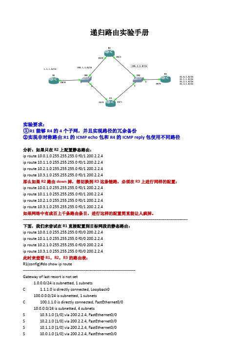
递归路由实验手册实验要求:①R1能够R4的4个子网,并且实现路径的冗余备份②实现非对称路由:R1的ICMP echo包和R4的ICMP reply包使用不同路径分析:如果只在R2上配置静态路由:ip route 10.0.1.0 255.255.255.0 f0/1 200.2.2.4ip route 10.1.1.0 255.255.255.0 f0/1 200.2.2.4ip route 10.2.1.0 255.255.255.0 f0/1 200.2.2.4ip route 10.3.1.0 255.255.255.0 f0/1 200.2.2.4那么如果R2路由down掉,想切换到R3这条链路,必须在R3上进行同样的配置:ip route 10.0.1.0 255.255.255.0 f0/1 200.2.2.4ip route 10.1.1.0 255.255.255.0 f0/1 200.2.2.4ip route 10.2.1.0 255.255.255.0 f0/1 200.2.2.4ip route 10.3.1.0 255.255.255.0 f0/1 200.2.2.4如果网络中有成百上千条路由条目,进行这样的配置简直能让人疯掉。
------------------------------------------------------------------------------------------------------------------------------ 下面,我们来尝试在R1直接配置到目标网段的静态路由:ip route 10.0.1.0 255.255.255.0 f0/0 200.2.2.4ip route 10.1.1.0 255.255.255.0 f0/0 200.2.2.4ip route 10.2.1.0 255.255.255.0 f0/0 200.2.2.4ip route 10.3.1.0 255.255.255.0 f0/0 200.2.2.4此时来查看R1,R2,R3的路由表:R1(config)#do show ip route--------------------------------------------------------------------------------------Gateway of last resort is not set1.0.0.0/24 is subnetted, 1 subnetsC 1.1.1.0 is directly connected, Loopback0100.0.0.0/24 is subnetted, 1 subnetsC 100.1.1.0 is directly connected, FastEthernet0/010.0.0.0/24 is subnetted, 4 subnetsS 10.3.1.0 [1/0] via 200.2.2.4, FastEthernet0/0S 10.2.1.0 [1/0] via 200.2.2.4, FastEthernet0/0S 10.1.1.0 [1/0] via 200.2.2.4, FastEthernet0/0S 10.0.1.0 [1/0] via 200.2.2.4, FastEthernet0/0R2(config)#do sh ip route----------------------------------------------------------------------------------------Gateway of last resort is not set100.0.0.0/24 is subnetted, 1 subnetsC 100.1.1.0 is directly connected, FastEthernet0/0C 200.2.2.0/24 is directly connected, FastEthernet0/110.0.0.0/24 is subnetted, 4 subnetsS 10.3.1.0 [1/0] via 200.2.2.4, FastEthernet0/1S 10.2.1.0 [1/0] via 200.2.2.4, FastEthernet0/1S 10.1.1.0 [1/0] via 200.2.2.4, FastEthernet0/1S 10.0.1.0 [1/0] via 200.2.2.4, FastEthernet0/1R3(config)#do show ip route-------------------------------------------------------------------------------------------Gateway of last resort is not set100.0.0.0/24 is subnetted, 1 subnetsC 100.1.1.0 is directly connected, FastEthernet0/0C 200.2.2.0/24 is directly connected, FastEthernet0/110.0.0.0/24 is subnetted, 4 subnetsS 10.3.1.0 [1/0] via 200.2.2.4, FastEthernet0/1S 10.2.1.0 [1/0] via 200.2.2.4, FastEthernet0/1S 10.1.1.0 [1/0] via 200.2.2.4, FastEthernet0/1S 10.0.1.0 [1/0] via 200.2.2.4, FastEthernet0/1可以看出R1,R2,R3都有了去往目标网络的完整路由表此时,如果ping目标网络可以通吗?当然不通,因为R1配置的静态路由只是告诉它去往4个目标网段要从f0/0接口发数据,到达R4的200.2.2.4。
思科基础实验(中英文对照)CCNA,CCNP实验

目录实验一路由器基本配置 (1)实验二静态路由 (3)实验三缺省路由 (5)实验四静态路由&缺省路由&CDP协议 (7)实验五三层交换机实现VLAN间通信 (9)实验六Vtp (11)实验七生成树STP (13)实验八RIP路由协议1 (17)实验九RIP路由协议2 (19)实验十OSPF单区域1 (21)实验十一OSPF单区域2 (22)实验十二OSPF单区域3 (24)实验十三EIGRP (26)实验十四ACL标准访问控制列表 (29)实验十五扩展ACL -1 (31)实验十六扩展ACL -2 (33)实验十七专家级访问控制列表 (36)实验十八动态NAT (37)实验十九NAT地址转换 (39)实验二十单臂路由 (41)实验二十一PPP chap认证 (43)实验二十二研究应用层和传输层协议 (44)实验二十三检查路由 (45)实验二十四研究ICMP 数据包 (47)实验二十五研究第2 层帧头 (49)实验二十六地址解析协议(ARP) (50)实验二十七中间设备用作终端设备 (52)实验二十八管理设备配置 (54)实验一路由器基本配置一、实验设备一台路由器,一台PC,配置线一条。
二、实验要求1.更改路由器名称为RA2.设置password为cisco1,secret为cisco2,vty为cisco3,并要求所有密码都加密。
3.关闭域名查找,命令输入同步。
4.配置以太网口的IP为202.119.249.2195.设置登陆提示信息6.对串行口进行描述(描述信息为:welcome to lixin lab)7.将上述信息保存到tftp server8.将实验过程配置写在记事本中进行粘贴。
9.配置VTY访问权限。
10.禁止路由器进行域名解析。
三、实验步骤Router>enableRouter#configure terminalRouter(config)#hostname RA 设置路由器名RA(config)#enable password cisco1 设置密码RA(config)#enable secret cisco2 设置加密密码RA (config)#no ip domain-lookup关闭域名查找(当我们打错命令时,不会去查找DNS,造成延时)RA (config)#line console 0RA (config-line)#logging synchronous命令输入达到同步(信息提示不会打断你的输入)RA (config-line)#exec-timeout 0 0 设置永久不超时RA (config-line)#exitRA(config)#line vty 0 4RA(config-line)#(enable)password cisco3 设置vty密码RA(config-line)#exitRA(config)#service password-encryption 对密码加密RA(config)#int fastEthernet 0/0RA(config-if)#ip address 202.119.249.1 255.255.255.0 对以太网口fa0/0配置IP RA(config-if)#no shutdown 开启端口RA(config-if)#exitRA(config)#banner motd & welcome welcome to ccna lab & 设置登陆提示信息RA(config)#int fa0/1RA(config-if)#description this is a fast port 描述端口信息RA(config-if)#exitRA(config)#copy running-config tftp 把信息保存到tftp实验二静态路由一、实验设备两台28系列型号路由器通过串口相连。
OSPF实验报告-CCNP

Page 4
4
配置
R5: interface Serial1/1 no ip address encapsulation frame-relay serial restart-delay 0 ! interface Serial1/1.1 multipoint ip address 172.8.100.5 255.255.255.0 ip ospf network broadcast frame-relay map ip 172.8.100.4 504 broadcast frame-relay map ip 172.8.100.6 506 broadcast no frame-relay inverse-arp R6: interface Serial1/1 ip address 172.8.100.6 255.255.255.0 encapsulation frame-relay ip ospf network broadcast ip ospf priority 0 serial restart-delay 0 frame-relay map ip 172.8.100.5 605 broadcast no frame-relay inverse-arp 5 R4: interface Serial1/1 ip address 172.8.100.4 255.255.255.0 encapsulation frame-relay ip ospf network broadcast serial restart-delay 0 frame-relay map ip 172.8.100.5 405 broadcast no frame-relay inverse-arp
Page 18
18
思科CCNP认证BGP的选路原则、联盟、过滤及默认路由配置分析

思科CCNP认证BGP的选路原则、联盟、过滤及默认路由配置分析本⽂讲述了思科CCNP认证BGP的选路原则、联盟、过滤及默认路由配置。
分享给⼤家供⼤家参考,具体如下:选路原则1: prefer highest weight (local to router).//weight值越⾼越优先。
2: prefer highest local preference(global within AS).//local-pref值越⾼越优先。
3:prefer route originated by the local router(next-hop =0.0.0.0)// 在前两条值相同的情况下,指定了下⼀跳优先。
4:prefer shortest AS path.// AS path 越短越优先。
5:prefer lowest origin code(IBGP<EBGP<incomplete).//按照IBGP<EBGP<incomplete的顺序进⾏选路,incomplete的优先级最⾼。
6:prefer lowest MED(exchange between autonomous systems)// MED值越低的越优先。
7:prefer EBGP path over IBGP path .//EBGP路径优先于IBGP路径。
8:prefer the path through the closest IGP neighbor.//IGP中邻居路径越近越优先。
9:prefer oldest route for EBGP paths .//EBGP中建邻时间越长越优先。
10:prefer the path with the lowest neighbor BGP router ID.// ⽐较router ID,越⼩的越优先。
11:prefer the path with the lowest neighbor IP address.//⽐较IP address,由于匹配ip地址时⼤多按照从⼩到⼤的顺序配置地址,所以⼀般情况下越⼩越优先。
EIGRP-CCNP
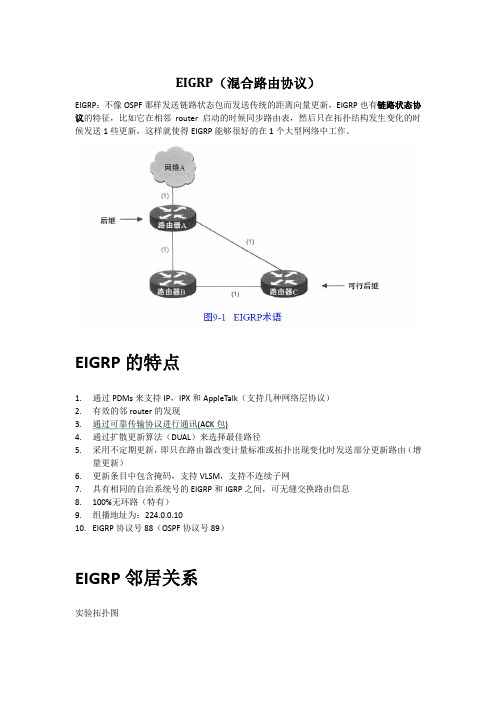
EIGRP(混合路由协议)EIGRP:不像OSPF那样发送链路状态包而发送传统的距离向量更新,EIGRP也有链路状态协议的特征,比如它在相邻router启动的时候同步路由表,然后只在拓扑结构发生变化的时候发送1些更新,这样就使得EIGRP能够很好的在1个大型网络中工作。
EIGRP的特点1.通过PDMs来支持IP,IPX和AppleTalk(支持几种网络层协议)2.有效的邻router的发现3.通过可靠传输协议进行通讯(ACK包)4.通过扩散更新算法(DUAL)来选择最佳路径5.采用不定期更新,即只在路由器改变计量标准或拓扑出现变化时发送部分更新路由(增量更新)6.更新条目中包含掩码,支持VLSM,支持不连续子网7.具有相同的自治系统号的EIGRP和IGRP之间,可无缝交换路由信息8.100%无环路(特有)9.组播地址为:224.0.0.1010.EIGRP协议号88(OSPF协议号89)EIGRP邻居关系实验拓扑图修改K值后(邻居关系就断了)修改K值Router(config-router)#metric weights 0 1 0 1 0 1Metric weight Tos K1 K2 K3 K4 K5 来修改K值,Tos默认为0在运行了EIGRP的router彼此进行交换信息之前,它们首先必须成为邻居,建立邻居关系必须满足以下3个条件:1.Hello信息或接收ACK2.AS号匹配3.K值注:如果不在1个AS内,router之间是不会共享路由信息的,也不会建立邻居关系,这样做的优点是在大型网络中可以减少特定某个AS内路由信息的传播。
EIGRP的五种包Hell o包hello包在邻居间进行交换。
一收到H e l l o包,路由器就会认为邻居还在工作。
邻居间进行交换。
确认邻居存在,邻居发现(比对AS, K值)ACK包应答包的发送时为了对收更新包进行应答Update包(交换路由)更新包被用来在邻居路由器间发送路由信息。
CCNP902必考的6个实验(拓扑搭建,配置详解)

CCNP902 必考的 6 个实验
目录 CCNP902 必考的 6 个实验............................................................................................................... 1 一、 EIGRP-OSPF 重分发(配置 distance).................................................................................. 2 1.1 拓扑环境....................................................................................................................... 2 1.2 搭建实验环境............................................................................................................... 2 1.3 题目要求....................................................................................................................... 5 1) 不配置 distance,正常配置 .................................................................................... 5 2) 配置 dist
CCNP Route Map基本实验--罪恶的温柔

Route Map基本实验
实验拓扑及相关ip设置:
实验要求:
实验步骤:
1.设置相关的ip
2.配置相关路由,记得把rip的自动汇总关了,在R2上双向重发布路由,在重分发的时候
调用定义的Route-Map(Route-Map在第3步设置)。
3.在R2上配置两个Route-map:
route-map rip-to-ospf:
在全局配置模式下:
route-map ospf-to-rip:
配置前缀列表:
ospf的环回接口默认是/32的。
将R3的环回接口设置为point-to-point类型后前缀列表可这样设置:
这个实验要注意的是,每条要求对应一条路由映射表,因为match是逻辑and的关系。
查看R1和R3的路由表:
metric值都是我们所设置的。
1.1.1.0我们设置的是O E1 metric 40 ,O E1的metric值是外部+内部的,串行链路的metric 为64,所以这里是40+64=104。
ospf重发布进来的默认是O E2。
CCNP小综合实验--罪恶的温柔

CCNP一个小综合实验:要求:1.SW1为VTP的Server,其他为Client2.SW1与SW2之间链路做捆绑3.PC1为vlan10,PC2为vlan204.SW1为vlan10的根,SW2为vlan10的备用根,SW2为vlan20的根,SW1为vlan20的备用根5.SW1与SW2通过HSRP来实现设备冗余6.SW1,SW2,中心路由器之间运行OSPF协议,当在SW1宇SW2上新增加网段的时候,中心路由器能够自动学习到新增加的网段。
7.中心与分公司之间通过DMVPN建立连接8.运行EIGRP协议,让公司之间的内网可以互通。
配置:基本配置:在各个路由器、交换机上配置ip在R1 R2 R3 R5上配置默认路由并做NATSW1 SW2与R5的接口采用路由接口,其他接口为交换端口1.sw1:vtp domain ciscosw2:vtp domain ciscovtp mode clientsw3:vtp domain ciscovtp mode client2.SW1:interface Port-channel1 switchport mode trunk !interface Port-channel2 switchport mode trunk interface FastEthernet1/3 switchport mode trunk channel-group 1 mode on !interface FastEthernet1/4 switchport mode trunk channel-group 1 mode on !interface FastEthernet1/5 switchport mode trunk channel-group 2 mode on !interface FastEthernet1/6 switchport mode trunk channel-group 2 mode on !SW2:!interface Port-channel1 switchport mode trunk !interface Port-channel2 switchport mode trunk !interface FastEthernet1/3 switchport mode trunk channel-group 1 mode on !interface FastEthernet1/4 switchport mode trunkchannel-group 1 mode on!interface FastEthernet1/5switchport mode trunkchannel-group 2 mode on!interface FastEthernet1/6switchport mode trunkchannel-group 2 mode on!SU为启用状态。
CCNP ICW实验手册

实验一:MPLS配置实验环境:三台路由器Ethernet接口相连,接口配置如图要求:在三台路由器相连的接口分别启用MPLS,查看相应的结果,在启用前使其在OSPF下互通。
步骤一:接口配置连通性,启用OSPF路由协议R1(config-if)#int e0/1R1(config-if)#ip add 10.1.1.1 255.255.255.0R1(config-if)#no shutdownR1(config)#int e0/0R1(config-if)#ip add 20.1.1.1 255.255.255.0R1(config-if)#no shR1(config)#router ospf 100 启用路由协议,发布接口R1(config-router)#net 10.1.1.0 0.0.0.255 area 0R1(config-router)#net 20.1.1.0 0.0.0.255 area 0R2(config)#int e0/1R2(config-if)#ip add 20.1.1.2 255.255.255.0R2(config-if)#no shR2(config-if)#int e0/0R2(config-if)#ip add 30.1.1.1 255.255.255.0R2(config-if)#no shR2(config)#router ospf 100R2(config-router)#net 20.1.1.0 0.0.0.255 area 0R2(config-router)#net 30.1.1.0 0.0.0.255 area 0R3(config)#int e0/1R3(config-if)#ip add 30.1.1.2 255.255.255.0R3(config-if)#no shR3(config-if)#int e0/0R3(config-if)#ip add 40.1.1.1 255.255.255.0R3(config-if)#no shR3(config-if)#exitR3(config)#router ospf 100R3(config-router)#net 30.1.1.0 0.0.0.255 area 0R3(config-router)#net 30.1.1.0 0.0.0.255 area 0步骤二:查看路由,并测试连通性R1#show ip route →查看路由表20.0.0.0/24 is subnetted, 1 subnetsC 20.1.1.0 is directly connected, Ethernet0/040.0.0.0/24 is subnetted, 1 subnetsO 40.1.1.0 [110/30] via 20.1.1.2, 00:00:15, Ethernet0/010.0.0.0/24 is subnetted, 1 subnetsC 10.1.1.0 is directly connected, Ethernet0/130.0.0.0/24 is subnetted, 1 subnetsO 30.1.1.0 [110/20] via 20.1.1.2, 00:00:15, Ethernet0/0 R2#show ip route20.0.0.0/24 is subnetted, 1 subnetsC 20.1.1.0 is directly connected, Ethernet0/140.0.0.0/24 is subnetted, 1 subnetsO 40.1.1.0 [110/20] via 30.1.1.2, 00:00:23, Ethernet0/0 10.0.0.0/24 is subnetted, 1 subnetsO 10.1.1.0 [110/20] via 20.1.1.1, 00:00:23, Ethernet0/130.0.0.0/24 is subnetted, 1 subnetsC 30.1.1.0 is directly connected, Ethernet0/0R3#show ip route →查看路由表,都也学到相关路由20.0.0.0/24 is subnetted, 1 subnetsO 20.1.1.0 [110/20] via 30.1.1.1, 00:00:06, Ethernet0/140.0.0.0/24 is subnetted, 1 subnetsC 40.1.1.0 is directly connected, Ethernet0/010.0.0.0/24 is subnetted, 1 subnetsO 10.1.1.0 [110/30] via 30.1.1.1, 00:00:06, Ethernet0/1 30.0.0.0/24 is subnetted, 1 subnetsC 30.1.1.0 is directly connected, Ethernet0/1R1#ping 40.1.1.1 →测试连通性Type escape sequence to abort.Sending 5, 100-byte ICMP Echos to 40.1.1.1, timeout is 2 seconds:!!!!!Success rate is 100 percent (5/5), round-trip min/avg/max = 4/4/4 ms R3#ping 10.1.1.1Type escape sequence to abort.Sending 5, 100-byte ICMP Echos to 10.1.1.1, timeout is 2 seconds:!!!!!Success rate is 100 percent (5/5), round-trip min/avg/max = 4/4/4 ms 步骤三:启用相关接口的MPLS,及快速转发功能R1(config)#ip cef →启用快速转发功能R1(config)#int e0/0R1(config-if)#mpls ip →接口启用MPLSR2(config)#ip cefR2(config)#int e0/1R2(config-if)#mpls ipR2(config-if)#int e0/0R2(config-if)#mpls ipR3(config)#ip cefR3(config)#int e0/1R3(config-if)#mpls ip步骤四:查看MPLS状态R1#show mpls forwarding-table →查看MPLS转发表Local Outgoing Prefix Bytes tag Outgoing Next Hop tag tag or VC or Tunnel Id switched interface16 16 40.1.1.0/24 0 Et0/0 20.1.1.217 Pop tag 30.1.1.0/24 0 Et0/0 20.1.1.2R2#show mpls forwarding-tableLocal Outgoing Prefix Bytes tag Outgoing Next Hop tag tag or VC or Tunnel Id switched interface16 Pop tag 40.1.1.0/24 0 Et0/0 30.1.1.217 Pop tag 10.1.1.0/24 0 Et0/1 20.1.1.1R3#show mpls forwarding-tableLocal Outgoing Prefix Bytes tag Outgoing Next Hop tag tag or VC or Tunnel Id switched interface16 Pop tag 20.1.1.0/24 0 Et0/1 30.1.1.117 17 10.1.1.0/24 0 Et0/1 30.1.1.1R1#show ip cef summary 查看CEF转发汇总信息及标记信息IP CEF with switching (Table Version 16), flags=0x016 routes, 0 reresolve, 0 unresolved (0 old, 0 new), peak 016 leaves, 18 nodes, 20896 bytes, 21 inserts, 5 invalidations0 load sharing elements, 0 bytes, 0 referencesuniversal per-destination load sharing algorithm, id 86C8F0BF3(0) CEF resets, 0 revisions of existing leavesResolution Timer: Exponential (currently 1s, peak 1s)0 in-place/0 aborted modificationsrefcounts: 4877 leaf, 4864 nodeTable epoch: 0 (16 entries at this epoch)Adjacency Table has 2 adjacenciesR2#show ip cef summaryIP CEF with switching (Table Version 17), flags=0x017 routes, 0 reresolve, 0 unresolved (0 old, 0 new), peak 017 leaves, 18 nodes, 21032 bytes, 22 inserts, 5 invalidations0 load sharing elements, 0 bytes, 0 referencesuniversal per-destination load sharing algorithm, id FCD3DE863(0) CEF resets, 0 revisions of existing leavesResolution Timer: Exponential (currently 1s, peak 1s)0 in-place/0 aborted modificationsrefcounts: 4879 leaf, 4864 nodeTable epoch: 0 (17 entries at this epoch)Adjacency Table has 4 adjacenciesR3#show ip cef summaryIP CEF with switching (Table Version 16), flags=0x016 routes, 0 reresolve, 0 unresolved (0 old, 0 new), peak 016 leaves, 18 nodes, 20896 bytes, 21 inserts, 5 invalidations0 load sharing elements, 0 bytes, 0 referencesuniversal per-destination load sharing algorithm, id 86B9347C3(0) CEF resets, 0 revisions of existing leavesResolution Timer: Exponential (currently 1s, peak 1s) 0 in-place/0 aborted modificationsrefcounts: 4877 leaf, 4864 nodeTable epoch: 0 (16 entries at this epoch)Adjacency Table has 2 adjacencies注:也可用show ip cef detail这条命令来查看详细信息R1#ping 40.1.1.1 测试连通性!!!!!R3#ping 10.1.1.1!!!!!步骤五:显示当前配置信息R1#show runhostname R1ip cef!interface Ethernet0/0ip address 20.1.1.1 255.255.255.0half-duplextag-switching ip!interface Ethernet0/1ip address 10.1.1.1 255.255.255.0half-duplex!router ospf 100network 10.1.1.0 0.0.0.255 area 0network 20.1.1.0 0.0.0.255 area 0!endR2#show runhostname R2!ip cef!interface Ethernet0/0ip address 30.1.1.1 255.255.255.0 half-duplextag-switching ip!interface Ethernet0/1ip address 20.1.1.2 255.255.255.0 half-duplextag-switching ip!router ospf 100network 20.1.1.0 0.0.0.255 area 0 network 30.1.1.0 0.0.0.255 area 0 !endR3#show runhostname R3!ip cef!interface Ethernet0/0ip address 40.1.1.1 255.255.255.0 half-duplex!interface Ethernet0/1ip address 30.1.1.2 255.255.255.0 half-duplextag-switching ip!router ospf 100network 30.1.1.0 0.0.0.255 area 0 network 40.1.1.0 0.0.0.255 area 0 !end实验二:ipsec site-to-siteVPN配置环境:两台路由器串口相连,接口配置如图要求:用两个LOOP口模拟VPN感兴趣流来建立IPSEC VPN,IKE1阶段用预共享密钥,IKE2阶段哈希算法用sha,加密算法用DES.步骤一:接口基本配置,并测试连通性R1(config)#int s0R1(config-if)#ip add 10.1.1.1 255.255.255.0R1(config-if)#clock rate 64000R1(config-if)#no shR1(config)#int loop 0R1(config-if)#ip add 1.1.1.1 255.255.255.0R2(config)#int s1R2(config-if)#ip add 10.1.1.2 255.255.255.0R2(config-if)#no shR2(config)#int loop 0R2(config-if)#ip add 1.1.2.1 255.255.255.0R1#ping 10.1.1.2 →测试连通性,再做IPSEC!!!!!Success rate is 100 percent (5/5), round-trip min/avg/max = 28/31/32 msR2#ping 10.1.1.1!!!!!Success rate is 100 percent (5/5), round-trip min/avg/max = 32/32/32 ms配置二:配置IKE1和IKE2两个阶段,并应用到接口R1(config)#crypto isakmp policy 10 →IKE1阶段策略R1(config-isakmp)#authen pre-share →将验证修改为预共享R1(config)#crypto isakmp key cisco address 10.1.1.2 →定义预共享密钥R1(config)#crypto ipsec transform myset esp-sha-hmac esp-des→定义2阶段的转换集R1(config)#access-list 100 permit ip 1.1.1.0 0.0.0.255 1.1.2.0 0.0.0.255→定义加密感兴趣流R1(config)#crypto map mymap 10 ipsec-isakmp →定义2阶段加密图% NOTE: This new crypto map will remain disabled until a peerand a valid access list have been configured.R1(config-crypto-map)#match address 100 →将列表应用到加密图R1(config-crypto-map)#set peer 10.1.1.2 →指定对等体R1(config-crypto-map)#set transform-set myset →将转换集映射到加密图R1(config)#int s0R1(config-if)#crypto map mymap →将加密图应用到接口R1(config)#ip route 1.1.2.0 255.255.255.0 20.1.1.2→指定隧道感兴趣流的路由走向R2(config)#crypto isakmp policy 10 →R2与R1端策略要匹配R2(config-isakmp)#authentication pre-shareR2(config-isakmp)#exitR2(config)#crypto isakmp key cisco address 10.1.1.1 →密钥一致,地址相互指R2(config)#crypto ipsec transform-set myset esp-des esp-sha-hmacR2(cfg-crypto-trans)#exit →两端必须匹配,默认即为tunnel模式R2(config)#access-list 102 permit ip 1.1.2.0 0.0.0.255 1.1.1.0 0.0.0.255→感兴趣流,两端互指R2(config)#crypto map mymap 10 ipsec-isakmp →加密图% NOTE: This new crypto map will remain disabled until a peerand a valid access list have been configured.R2(config-crypto-map)#set peer 10.1.1.1 →对端的物理地址R2(config-crypto-map)#set transform-set mysetR2(config-crypto-map)#match address 102R2(config-crypto-map)#exitR2(config)#ip route 1.1.1.0 255.255.255.0 10.1.1.1 →加密图感兴趣流的路由R2(config)#int s1R2(config-if)#crypto map mymap →加密映射应用到接口下步骤三:测试流是否加密,直接用接口ping出R1#ping 1.1.2.1!!!!!Success rate is 100 percent (5/5), round-trip min/avg/max = 32/33/36 msR2#ping 1.1.1.1!!!!!Success rate is 100 percent (5/5), round-trip min/avg/max = 32/33/36 ms分别在R1和R2上查看两个阶段的关联R1#show crypto isakmp sa →没有任何关联dst src state conn-id slotR2#show crypto isakmp sadst src state conn-id slotR1#show crypto ipsec sa 没有任何加密包,关联也没有建立interface: Serial0Crypto map tag: mymap, local addr. 10.1.1.1local ident (addr/mask/prot/port): (1.1.1.0/255.255.255.0/0/0)remote ident (addr/mask/prot/port): (1.1.2.0/255.255.255.0/0/0)current_peer: 10.1.1.2PERMIT, flags={origin_is_acl,}#pkts encaps: 0, #pkts encrypt: 0, #pkts digest 0#pkts decaps: 0, #pkts decrypt: 0, #pkts verify 0#pkts compressed: 0, #pkts decompressed: 0#pkts not compressed: 0, #pkts compr. failed: 0, #pkts decompress failed: 0 #send errors 0, #recv errors 0local crypto endpt.: 10.1.1.1, remote crypto endpt.: 10.1.1.2path mtu 1500, media mtu 1500current outbound spi: 0inbound esp sas:inbound ah sas:inbound pcp sas:outbound esp sas:outbound ah sas:outbound pcp sas:R2#show crypto ipsec sainterface: Serial1Crypto map tag: mymap, local addr. 10.1.1.2local ident (addr/mask/prot/port): (1.1.2.0/255.255.255.0/0/0)remote ident (addr/mask/prot/port): (1.1.1.0/255.255.255.0/0/0)current_peer: 10.1.1.1PERMIT, flags={origin_is_acl,}#pkts encaps: 0, #pkts encrypt: 0, #pkts digest 0#pkts decaps: 0, #pkts decrypt: 0, #pkts verify 0#pkts compressed: 0, #pkts decompressed: 0#pkts not compressed: 0, #pkts compr. failed: 0, #pkts decompress failed: 0 #send errors 0, #recv errors 0local crypto endpt.: 10.1.1.2, remote crypto endpt.: 10.1.1.1path mtu 1500, media mtu 1500current outbound spi: 0inbound esp sas:inbound ah sas:inbound pcp sas:outbound esp sas:outbound ah sas:outbound pcp sas:步骤四:用扩展ping来触发感兴趣流量R1#ping ipTarget IP address: 1.1.2.1Repeat count [5]: 10 →将包调为10个,否则一个ping看不到效果Extended commands [n]: ySource address or interface: 1.1.1.1Sending 10, 100-byte ICMP Echos to 1.1.2.1, timeout is 2 seconds:....!!!!!! →已经触发了感兴趣流,并且ping通Success rate is 60 percent (6/10), round-trip min/avg/max = 84/84/84 ms步骤五:再次查看两个阶段的关联,以及加密情况R1#show crypto isa sa →IKE1阶段关联已建立为快速模式dst src state conn-id slot10.1.1.2 10.1.1.1QM_IDLE 1 0R1#show crypto ipsec sa→IKE2阶段关联建立,并加密了流量,隧道也已成功建立interface: Serial0Crypto map tag: mymap, local addr. 10.1.1.1local ident (addr/mask/prot/port): (1.1.1.0/255.255.255.0/0/0)remote ident (addr/mask/prot/port): (1.1.2.0/255.255.255.0/0/0)current_peer: 10.1.1.2PERMIT, flags={origin_is_acl,}#pkts encaps: 6, #pkts encrypt: 6, #pkts digest 6#pkts decaps: 6, #pkts decrypt: 6, #pkts verify 6#pkts compressed: 0, #pkts decompressed: 0#pkts not compressed: 0, #pkts compr. failed: 0, #pkts decompress failed: 0 #send errors 14, #recv errors 0local crypto endpt.: 10.1.1.1, remote crypto endpt.: 10.1.1.2path mtu 1500, media mtu 1500current outbound spi: 84AEB2E6inbound esp sas:spi: 0x1E44AB1D(507816733)transform: esp-des esp-sha-hmac ,in use settings ={Tunnel, }slot: 0, conn id: 2000, flow_id: 1, crypto map: mymapsa timing: remaining key lifetime (k/sec): (4607999/3520)IV size: 8 bytesreplay detection support: Yinbound ah sas:inbound pcp sas:outbound esp sas:spi: 0x84AEB2E6(2226041574)transform: esp-des esp-sha-hmac ,in use settings ={Tunnel, }slot: 0, conn id: 2001, flow_id: 2, crypto map: mymapsa timing: remaining key lifetime (k/sec): (4607999/3520)IV size: 8 bytesreplay detection support: Youtbound ah sas:outbound pcp sas:R2#show crypto isa sadst src state conn-id slot10.1.1.2 10.1.1.1 QM_IDLE 1 0R2#show crypto ipsec sainterface: Serial1Crypto map tag: mymap, local addr. 10.1.1.2local ident (addr/mask/prot/port): (1.1.2.0/255.255.255.0/0/0)remote ident (addr/mask/prot/port): (1.1.1.0/255.255.255.0/0/0)current_peer: 10.1.1.1PERMIT, flags={origin_is_acl,}#pkts encaps: 6, #pkts encrypt: 6, #pkts digest 6#pkts decaps: 6, #pkts decrypt: 6, #pkts verify 6#pkts compressed: 0, #pkts decompressed: 0#pkts not compressed: 0, #pkts compr. failed: 0, #pkts decompress failed: 0 #send errors 0, #recv errors 0local crypto endpt.: 10.1.1.2, remote crypto endpt.: 10.1.1.1path mtu 1500, media mtu 1500current outbound spi: 1E44AB1Dinbound esp sas: →进站流已经产生spi: 0x84AEB2E6(2226041574)transform: esp-des esp-sha-hmac ,in use settings ={Tunnel, }slot: 0, conn id: 2000, flow_id: 1, crypto map: mymapsa timing: remaining key lifetime (k/sec): (4607999/3502)IV size: 8 bytesreplay detection support: Yinbound ah sas:inbound pcp sas:outbound esp sas: →出站流已经产生spi: 0x1E44AB1D(507816733)transform: esp-des esp-sha-hmac ,in use settings ={Tunnel, }slot: 0, conn id: 2001, flow_id: 2, crypto map: mymapsa timing: remaining key lifetime (k/sec): (4607999/3502)IV size: 8 bytesreplay detection support: Youtbound ah sas:outbound pcp sas:配置五:查看当前的配置R1#show runhostname R1!crypto isakmp policy 10authentication pre-sharecrypto isakmp key cisco address 10.1.1.2!crypto ipsec transform-set myset esp-des esp-sha-hmac!crypto map mymap 10 ipsec-isakmpset peer 10.1.1.2set transform-set mysetmatch address 102!interface Loopback0ip address 1.1.1.1 255.255.255.0!interface Serial0ip address 10.1.1.1 255.255.255.0clockrate 64000crypto map mymap!ip route 1.1.2.0 255.255.255.0 10.1.1.2!access-list 102 permit ip 1.1.1.0 0.0.0.255 1.1.2.0 0.0.0.255 !endR2#show runhostname R2!crypto isakmp policy 10authentication pre-sharecrypto isakmp key cisco address 10.1.1.1!crypto ipsec transform-set myset esp-des esp-sha-hmac!crypto map mymap 10 ipsec-isakmpset peer 10.1.1.1set transform-set mysetmatch address 102!interface Loopback0ip address 1.1.2.1 255.255.255.0!interface Serial1ip address 10.1.1.2 255.255.255.0crypto map mymap!ip route 1.1.1.0 255.255.255.0 10.1.1.1!access-list 102 permit ip 1.1.2.0 0.0.0.255 1.1.1.0 0.0.0.255 !end实验三:GRE VPN的配置环境:三台路由器串口相连,接口配置如图要求:在R1和R3之间建立GRE隧道,地址如图步骤一:接口配置连通性,R1(config)#int s0R1(config-if)#ip add 20.1.1.1 255.255.255.0R1(config-if)#no shR1(config-if)#int lo0R1(config-if)#ip add 10.1.1.1 255.255.255.0 →虚拟私有网络R1(config)#ip route 0.0.0.0 0.0.0.0 20.1.1.2 →上互联网的缺省路由ISP(config)#int s0 →ISP路由器虚拟互联网ISP(config-if)#ip add 30.1.1.1 255.255.255.0ISP(config-if)#cl ra 64000ISP(config-if)#no shISP(config-if)#int s1ISP(config-if)#ip add 20.1.1.2 255.255.255.0ISP(config-if)#cl ra 64000ISP(config-if)#no shR3(config)#int s1R3(config-if)#ip add 30.1.1.2 255.255.255.0R3(config-if)#no shR3(config-if)#int loo 0R3(config-if)#ip add 40.1.1.1 255.255.255.0→虚拟私有网络R3(config-if)#exitR3(config)#ip route 0.0.0.0 0.0.0.0 30.1.1.2→上互联网的缺省路由步骤二:测试哪些可达,哪些不可达R3#ping 10.1.1.1 →由于ISP没有私网的路由Type escape sequence to abort.Sending 5, 100-byte ICMP Echos to 10.1.1.1, timeout is 2 seconds:U.U.USuccess rate is 0 percent (0/5)R3#ping 20.1.1.1 →合法地址是能够通讯的Type escape sequence to abort.Sending 5, 100-byte ICMP Echos to 20.1.1.1, timeout is 2 seconds:!!!!!Success rate is 100 percent (5/5), round-trip min/avg/max = 56/60/64 ms步骤三:实施GRE隧道技术R1(config)#int tunnel 0 →进入隧道接口R1(config-if)#ip add 100.1.1.1 255.255.255.0 →指定IP地址,两端要在一个网段R1(config-if)#tunnel source s0 →指定承载隧道的源和目的接口R1(config-if)#tunnel destination 30.1.1.2R1(config-if)#no shR1(config)#ip route 40.1.1.0 255.255.255.0 tunnel0 →为私有网络指路由走tunnel接口R3(config)#int tunnel 0R3(config-if)#ip add 100.1.1.2 255.255.255.0R3(config-if)#tunnel source s1 →互指源和目的R3(config-if)#tunnel destination 20.1.1.1R3(config-if)#no shR3(config-if)#exitR3(config)#ip route 10.1.1.0 255.255.255.0 tunnel 0 →指对端的私有网络步骤四:做PING测试R1#ping 40.1.1.1 →都已PING通,证明GRE隧道已建立Type escape sequence to abort.Sending 5, 100-byte ICMP Echos to 40.1.1.1, timeout is 2 seconds:!!!!!Success rate is 100 percent (5/5), round-trip min/avg/max = 72/72/76 msR1#ping 10.1.1.1Type escape sequence to abort.Sending 5, 100-byte ICMP Echos to 10.1.1.1, timeout is 2 seconds:!!!!!Success rate is 100 percent (5/5), round-trip min/avg/max = 72/72/76 ms步骤五:验证结果R1#show int tunnel 0Tunnel0 is up, line protocol is up →tunnel接口已经UPHardware is TunnelInternet address is 100.1.1.1/24R3#show int tunnel 0Tunnel0 is up, line protocol is upHardware is TunnelInternet address is 100.1.1.2/24R1#show int tunnel 0 accounting →tunnel接口的统计信息,包的统计Tunnel0Protocol Pkts In Chars In Pkts Out Chars Out IP 10 1000 10 1000R3#show int tunnel 0 accountingTunnel0Protocol Pkts In Chars In Pkts Out Chars Out IP 10 1000 10 1000步骤六:显示当前配置R1#show runhostname R1!interface Loopback0ip address 10.1.1.1 255.255.255.0!interface Tunnel0ip address 100.1.1.1 255.255.255.0tunnel source Serial0tunnel destination 30.1.1.2!interface Serial0ip address 20.1.1.1 255.255.255.0!ip route 0.0.0.0 0.0.0.0 20.1.1.2ip route 40.1.1.0 255.255.255.0 Tunnel0!EndISP#show runhostname ISP!interface Serial0ip address 30.1.1.1 255.255.255.0clockrate 64000!interface Serial1ip address 20.1.1.2 255.255.255.0clockrate 64000!endR3#show runhostname R3!interface Loopback0ip address 40.1.1.1 255.255.255.0!interface Tunnel0ip address 100.1.1.2 255.255.255.0tunnel source s1tunnel destination 20.1.1.1!interface Serial1ip address 30.1.1.2 255.255.255.0!ip route 0.0.0.0 0.0.0.0 30.1.1.2ip route 10.1.1.0 255.255.255.0 Tunnel0 !end实验四:静态VS.动态Crypto Map静态的crypto map条目的一个问题是,必须指定远程对等设备的IP地址.如果本地或者远程R动态获得它们的地址信息是,会变得非常困难.topology10.1.1.0/24-router1-172.16.171.10----172.16.171.20-router2-10.1.2.0/24Basic routeRouter1:ip route 0.0.0.0 0.0.0.0 172.16.171.20Router2:ip route 0.0.0.0 0.0.0.0 172.16.171.10IKE Phase I policyRouter1:crypto isakmp policy 1authentication per-sharedhash md5encryption 3desgroup 2crypto isakmp 6 key cisco address 172.16.171.20Router2:crypto isakmp policy 1authentication per-sharedhash md5encr 3desgroup 2crypto isakmp key cisco address 0.0.0.0 0.0.0.0IPSec Phase II policyRouter1:crypto ipsec transform-set cisco esp-des esp-sha-hmacaccess-list 101 permit ip 10.1.1.0 0.0.0.255 10.1.2.0 0.0.0.255Static Crypto Mapcrypto map vpn 10 ipsec-isakmpset peer 172.16.171.20set transform-set ciscomatch address list 101Router2:crypto ipsec transform-set cisco esp-des esp-sha-hmacDynamic Crypto Mapcrypto dynamic-map dynamap 10set transform-set ciscocrypto map vpn 10 ipsec-isakmp dynamic dynamapApply VPN ConfigurationRouter1:interface s0crypto map vpnRouter2:interface s0crypto map vpn实验五:IPSEC over GRE Configuration技术特点利用tunnel跑动态路由协议,ipsec over gretopology1.1.1.12.2.2.2| |Lo0 Lo0| |10.1.1.0/24-router1-172.16.171.10--------------172.16.171.20-router2-10.1.2.0 /24| || tunnel |----------------------------------------------------------Basic configurationRouter1:Interface tunnel 12ip add 192.168.100.1 255.255.255.0tunnel source 172.16.171.10tunnel dest 172.16.171.20router eigrp 100no aunet 1.1.1.0 0.0.0.255net 10.1.1.0 0.0.0.255net 192.168.100.0 0.0.0.255Router2:Interface tunnel 21ip add 192.168.100.2 255.255.255.0tunnel source 172.16.171.20tunnel dest 172.16.171.10router eigrp 100no aunet 2.2.2.0 0.0.0.255net 10.1.2.0 0.0.0.255net 192.168.100.0 0.0.0.255IKE Phase I policyRouter1:crypto isakmp policy 1authentication per-sharedhash md5encr 3desgroup 2crypto isakmp key cisco address 2.2.2.2 or 172.16.171.20Router2:crypto isakmp policy 1authentication per-sharedhash md5encr 3desgroup 2crypto isakmp key cisco address 1.1.1.1 or 172.16.171.10IPSec Phase II policyRouter1:crypto ipsec transform-set cisco esp-des esp-sha-hmacaccess-list 101 permit ip 10.1.1.0 0.0.0.255 10.1.2.0 0.0.0.255 crypto map cisco 10 ipsec-isakmpset peer 2.2.2.2 or 172.16.171.20set transform-set ciscoset pfsmatch address 101Router2:crypto ipsec transform-set cisco esp-des esp-sha-hmacaccess-list 101 permit ip 10.1.2.0 0.0.0.255 10.1.1.0 0.0.0.255 crypto map cisco 10 ipsec-isakmpset peer 1.1.1.1 or 172.16.171.10set transform-set ciscoset pfsmatch address 101Apply VPN ConfigurationRouter1:interface s0crypto map ciscointerface tu 12crypto map ciscoRouter2:interface s0crypto map ciscointerface tu 21crypto map cisconote:peer 设置为 1.1.1.1 or 2.2.2.2 时封装格式如下ip – gre – ip - esp – ip – datapeer 设置为 172.16.171.10 or 172.16.171.20 时封装格式如下ip – esp – ip – data实验6:GRE over IPSEC Configuration技术特点IPsec (ESP) tunnels only IP unicast trafficGRE encap non-ip and ip multicast or broadcast packets into ip unicast packets Using a GRE tunnel inside an ipsec tunnel uses only three SA (at maximum)topology10.1.1.0/24-router1-172.16.100.1----172.16.100.2-router2-10.1.2.0/24| || tunnel |-------------------------------------192.168.100.0/24Basic configurationRouter1:Interface tunnel 12ip add 192.168.100.1 255.255.255.0tunnel source 172.16.100.1tunnel dest 172.16.100.2router eigrp 100no aunet 10.1.1.0 0.0.0.255net 192.168.100.0 0.0.0.255Router2:Interface tunnel 21ip add 192.168.100.2 255.255.255.0tunnel source 172.16.100.2tunnel dest 172.16.100.1router eigrp 100no aunet 10.1.2.0 0.0.0.255net 192.168.100.0 0.0.0.255IKE Phase I policyRouter1:crypto isakmp policy 1authentication per-sharedhash md5encr 3desgroup 2crypto isakmp key cisco address 172.16.100.2Router2:crypto isakmp policy 1authentication per-sharedhash md5encr 3desgroup 2crypto isakmp key cisco address 172.16.100.1IPSec Phase II policyRouter1:crypto ipsec transform-set cisco esp-des esp-sha-hmac mode transportaccess-list 101 permit gre any anycrypto map cisco 10 ipsec-isakmpset peer 172.16.100.2set transform-set ciscoset pfsmatch address 101Router2:crypto ipsec transform-set cisco esp-des esp-sha-hmac mode transportaccess-list 101 permit gre any anycrypto map cisco 10 ipsec-isakmpset peer 172.16.100.1set transform-set ciscoset pfsmatch address 101Apply VPN ConfigurationRouter1:interface e0/0crypto map ciscoRouter2:interface e0/0crypto map cisco实验七:Ezvpn的配置环境:路由器(cisco)r1在一个公司的总部为EZVPN的server,远程internet用户要访问总部的内网,远程用户用的是cisco的EZVPN软件。
(整理)cisco实训项目案例(路由交换篇)-CCNA-CCNP-CCIE-实验项目.

实验1 路由器基础命令回顾一、实验目的通过本节的练习回顾、熟悉一期课程中涉及到的路由器的相关指令。
掌握路由器的基础配置。
二、实验需要的知识点一期路由器的基础知识。
三、实验步骤1、改写主机名。
把路由器的主机名改成:RouterA. 。
在全局模式下使用指令的关键字:hostname name2、配置密码。
进入特权模式的密码为cisco。
配置控制台的密码:cisco配置远程登录的密码:cisco在全局模式下使用指令的关键字:enable password password在全局模式下使用指令的关键字:line vty 0 4loginpassword password在全局模式下使用指令的关键字:line console 0loginpassword password3、配置时钟。
在全局模式下使用指令的关键字:clock set hh::mm::ss mm:dd:yy4、配置接口ip地址。
在路由器的环回接口配置ip地址:1.1.1.1/24 。
在e0接口上配置ip地址:192.1.1.1/24在全局模式下使用指令的关键字:interface interface在接口模式下使用指令的关键字:ip address ip address mask5、退出,有三种方法。
endexitlogout6、保存配置,有两种方法。
copy running-config stratup-configwrite7、停止域名解析查询。
在全局模式下使用指令的关键字:no ip domain lookup四、检测在特权模式下使用:show version2、在特权模式下使用:show interface {interface}3、在特权模式下使用:show flash4、在特权模式下使用:show running-config5、在特权模式下使用:show startup-config6、在特权模式下使用:show history7、在特权模式下使用:show clock8、ping 自己的环回口地址。
- 1、下载文档前请自行甄别文档内容的完整性,平台不提供额外的编辑、内容补充、找答案等附加服务。
- 2、"仅部分预览"的文档,不可在线预览部分如存在完整性等问题,可反馈申请退款(可完整预览的文档不适用该条件!)。
- 3、如文档侵犯您的权益,请联系客服反馈,我们会尽快为您处理(人工客服工作时间:9:00-18:30)。
SPOTO 全球 培训 ● 项目 ● 人才 SPOTO IT 人才培训机构 ● IT 人才解决方案 ● CCIE 实验室 ● BOOTCAMP 全真IT 项目实战
1 CCNP ROUTE EIGRP 综合实验
版本
V1.0
密级
☑开放
☐内部 ☐机密 类型
☐讨论版 ☐测试版 ☑正式版
1 实验拓扑
2 IP 地址规划
拓扑中的IP 地址段采用:172.8.AB.X/24:
SPOTO 全球培训●项目●人才
SPOTO IT人才培训机构●IT人才解决方案●CCIE实验室●BOOTCAMP 全真IT项目实战2
其中AB为两台路由器编号组合,例如:R3-R6之间的AB为36,X为路由器编号,例如:R3的X=3
BBR1/R2/R5之间的网段为:172.8.123.X/24,其中X为路由器编号。
R4/R5/R6之间的网段为:172.8.100.X/24,其中X为路由器编号。
所有路由器都有一个loopback 0接口,地址格式为:X.X.X.X/32,其中X为路由器编号。
3实验需求
1、R4/R5/R6通过帧中继交换机FRSW连接,为Hub&Spoke模式,其中R5为Hub,BBR1为骨
干路由器,帧中继PVC要求采用静态映射,DLCI号详见拓扑图。
2、每台路由器都配置相应的环回接口,具体查看IP地址规划,按照实验拓扑图来宣告路由器接口到
相应的EIGRP进程,没有具体说明的可任意宣告,要求关闭自动汇总功能。
3、在R2,R3上进行EIGRP的链路验证(采用MD5进行认证),密码为:SPOTO
4、BBR1上有一个loopback 1接口IP为:199.172.1.254/24,199.172.2.254/24,
199.172.3.254/24(采用secondary的方式配置IP),将它们宣告到EIGRP100中,采用手动汇总的方式在BBR1上对BBR1的loopback1接口的地址进行汇总,观察R2上的路由表。
5、要求EIGRP AS 8里面的路由器能收到BBR1的这条汇总路由。
6、要求R6到达BBR1的这条汇总路由实现不等价的负载均衡。
7、配置R2和R5使得它们在EGRIP 100的进程下不会接收到任何的EIGRP查询信息,并且不会发
送任何关于它们的路由信息给它的EIGRP 100的邻居。
8、要求采用最多2条静态路由条目实现实现全网互通。
