CNC哈斯机器操作指南
哈斯(haas)加工中心实际操作介绍资料

立式加工中心培训资料2007 年5 月内容目录安全 (1)操作⋯⋯⋯ (4)基本介绍⋯⋯⋯⋯⋯⋯⋯ (4)坐标体系⋯ (4)绝对定位法和增量定位 (5)用代码编程 (5)机床缺省值 (5)程序格式 (6)固定循环 (7)刀具交换装置安装步骤..................................... . (8)操作员控制面板 (9)实时计时器 (12)键盘 (12)通电/断电⋯⋯⋯ (20)手动操作⋯⋯ (20)自动操作⋯⋯⋯ (21)创建、编辑和保存程序 (23)程序输入/输出⋯ (26)试运行操作 (30)显示 (30)行程限制⋯⋯⋯⋯⋯⋯ (44)运行-停止-轻推-继续 (45)编程⋯⋯ (46)工作坐标系统 (46)编程结构 (46)字母地址代码 (48)技巧与窍门 (51)高速机械加工(可选) (61)第4轴编程 (62)子程序 (65)刀具功能(Tnn) (73)侧挂式刀具交换装置 (74)用VF系统计算机数控铣床攻丝............................ . (83)铣刀补偿 (86)高级编辑 (98)G代码(预备功能) (105)M代码(各种功能) (151)设置 (160)在工作中不要发生这种情况所有的铣削设备如旋转件、皮带、滑轮、高压电、噪音、压缩空气等均有危险存在,所以在使用CNC备及其组件时,为避免人身伤害及机械损坏,必严格遵守相应的安全守则。
操作安全必读‹ 只有经过授权的人员方可使用本机,未经培训人员在使用机床时可能对人身及机床造成伤害以及由于不正确的操作造成的问题不属保修范围内。
‹ 操作前请认真检查零配件及刀具,所有损坏的配件和刀具应当由专业人员修理或替换。
一旦有部件显示异常,不要操作,应及时联系您的车间质检人员。
‹ 操作机床时使用合适的眼、耳保护装置。
推荐使用ANSI认证的护目镜和OSHA认证的耳罩。
‹ 操作机床时一定确保其门关闭,门已正确互锁,旋转的刀具可能造成严重的人身伤害,当程序在运行中时,机床平台及主轴头能够在任一时间向任一方向做非常快的移动。
美国哈斯CNC转 台 操 作 手 册
LIMITS and EXCLUSIONS of WARRANTY
Except as provided above, buyer agrees that all warranties express or implied, as to any matter whatsoever, including but not limited to warranties of merchantability and fitness for a particular purpose are excluded. Components subject to wear during normal use and over time such as paint, window finish and condition, light bulbs, seals, chip removal system, etc., are excluded from this warranty.
This Warranty Certificate supersedes any and all other agreements, either oral or in this writing, between the parties hereto with respect to the warranties, limitations of liability and/or damages regarding the Machine or Components, and contains all of the covenants and agreements between the parties with respect to such warranties, liability limitations and/or damages. Each party to this Warranty Certificate acknowledges that no representations, inducements, promises, or agreements, orally or otherwise, have been made by any party, or anyone acting on behalf of any party, which are not embodied herein regarding such warranties, liability limitations and/or damages, and that no other agreement, statement, or promise not contained in this Warranty Certificate shall be valid or binding regarding such warranties, liability limitations and damages.
CNC哈斯机器操作指南
开机启动 Start Up Procedure
1. 在关机状态下,按绿色的“Power On(开机)”按钮,机器随之进入 启动状态,请耐心等待。 If the machine is off, press the green “POWER ON” button. This will begin a startup cycle that may take a few minutes to complete.
5. 按“SELECT PROG(选择程序)”键。 Press “SELECT PROG” key.
18
从USB导入程序 Loading a Program into Memory From USB
显示屏上会显示程序内容。如果程序内容背景色是蓝色,按两次“MEM (记忆)”按键使其转换为白色。只有当程序内容背景色为白色时,才表 示程序即将启动。 The program will appear in the upper left window of the display screen. A white background means the program is ready to run. If the background is blue, press “MEM” key to activate.
31
使用对刀仪设置刀具长度
Using Touch Setter to Set Tool Length
7. 按“ENTER(输入)”键。 Press the “ENTER” key.
32
使用对刀仪设置刀具长度
Using Touch Setter to Set Tool Length
8. 利用方向键在屏幕上选择刀具种类:铣刀,钻头,丝攻。选好以后, 按“ENTER(输入)”键。
haas机床操作
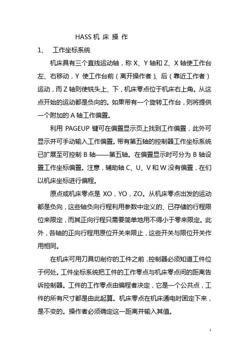
HASS机床操作1、工作坐标系统机床具有三个直线运动轴,称X、Y轴和Z、X轴使工作台左、右移动,Y使工作台前(离开操作者)、后(靠近工作者)运动,而Z轴则使铣头上、下,机床零点位于机床右上角。
从这点开始的运动都是负向的。
如果带有一个旋转工作台,则将提供一个附加的A轴工作偏臵。
利用PAGEUP键可在偏臵显示页上找到工作偏臵,此外可显示并可手动输入工作偏臵。
带有第五轴的控制器工作坐标系统已扩展至可控制B轴——第五轴。
在偏臵显示时可分为B轴设臵工作坐标偏臵。
注意,辅助轴C、U、V和W没有偏臵,在们以机床坐标进行偏程。
原点或机床零点是XO,YO,ZO。
从机床零点出发的运动都是负向,这些轴负向行程利用参数中定义的、已存储的行程限位来限定,而其正向行程只需要简单地用不得小于零来限定。
此外,各轴的正向行程用原位开关来限止,这些开关与限位开关作用相同。
在机床可用刀具切削你的工件之前,控制器必须知道工件位于何处。
工件坐标系统把工件的工作零点与机床零点间的距离告诉控制器。
工件的工作零点由编程者决定,它是一个公共点,工件的所有尺寸都是由此起算。
机床零点在机床通电时固定下来,是不变的。
操作者必须确定这一距离并输入其值。
通电时控制器自动选择G54系统。
如你不希望使用这一系统,在G54中使其X、Y、Z值为零,或选择另一工作偏臵。
G54至G59或G110至G129偏臵可以利用PARTZEROSET(工作零点设臵)键来设臵。
将各轴移动至工件的工作零点,并用光标选好特定的轴和工件号。
按PARTZEROSET键,则当前的机床位臵将自动储存于该地址内。
这只有在选定工作零点偏臵显示时有效。
请注意,输入一个非零的Z工作偏臵将和一个自动输入刀具长度偏臵操作产生干涉。
在表中输入工作坐标时仅需给一个数字。
例如在G54内输入X值为X2.00时,可用光标搜索该列并只需输入2.0即可。
工作坐标数值通常输入一个正数,但参数57的‚NEG,WOVKOFFSET‛位设臵为1时例外,在这情况下,工作坐标数应以负数输入。
哈斯(haas)加工中心操作手册

立式加工中心培训资料2007 年5 月内容目录安全 (1)操作⋯⋯⋯ (4)基本介绍⋯⋯⋯⋯⋯⋯⋯ (4)坐标体系⋯ (4)绝对定位法和增量定位 (5)用代码编程 (5)机床缺省值 (5)程序格式 (6)固定循环 (7)刀具交换装置安装步骤..................................... . (8)操作员控制面板 (9)实时计时器 (12)键盘 (12)通电/断电⋯⋯⋯ (20)手动操作⋯⋯ (20)自动操作⋯⋯⋯ (21)创建、编辑和保存程序 (23)程序输入/输出⋯ (26)试运行操作 (30)显示 (30)行程限制⋯⋯⋯⋯⋯⋯ (44)运行-停止-轻推-继续 (45)编程⋯⋯ (46)工作坐标系统 (46)编程结构 (46)字母地址代码 (48)技巧与窍门 (51)高速机械加工(可选) (61)第4轴编程 (62)子程序 (65)刀具功能(Tnn) (73)侧挂式刀具交换装置 (74)用VF系统计算机数控铣床攻丝............................ . (83)铣刀补偿 (86)高级编辑 (98)G代码(预备功能) (105)M代码(各种功能) (151)设置 (160)在工作中不要发生这种情况所有的铣削设备如旋转件、皮带、滑轮、高压电、噪音、压缩空气等均有危险存在,所以在使用CNC备及其组件时,为避免人身伤害及机械损坏,必严格遵守相应的安全守则。
操作安全必读‹ 只有经过授权的人员方可使用本机,未经培训人员在使用机床时可能对人身及机床造成伤害以及由于不正确的操作造成的问题不属保修范围内。
‹ 操作前请认真检查零配件及刀具,所有损坏的配件和刀具应当由专业人员修理或替换。
一旦有部件显示异常,不要操作,应及时联系您的车间质检人员。
‹ 操作机床时使用合适的眼、耳保护装置。
推荐使用ANSI认证的护目镜和OSHA认证的耳罩。
‹ 操作机床时一定确保其门关闭,门已正确互锁,旋转的刀具可能造成严重的人身伤害,当程序在运行中时,机床平台及主轴头能够在任一时间向任一方向做非常快的移动。
哈斯开机,关机,对刀操作。G代码和M代码介绍
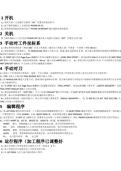
1开机1.) 将电气柜上主电源开头扳到“ON”位置并给机床供气。
2.) 按下操作面板左上方绿色的POWER ON键。
3.) 控制系统初始化结束后按下POWER UP/RESTART键完成机床的初始化。
2 关机按下操作面板左上方红色的POWER OFF键后将主电源开关扳回“OFF”位置并关闭气源。
3 手动对工件坐标系1.) 确定使用的坐标系(例如G54)以及工件基面(通常为工件最上面)并准备一个块规(例如40mm)。
2.) 将块规放在工件基面上,按HANDLE/JOG键进入手轮方式,按+Z或-Z选择移动Z轴,把主轴头移到靠近块规时应缓慢移动Z 轴直到主轴端面正好靠上块规面。
3.) 按OFSET键后再按Page Down键翻到工件零点偏置页面显示(WORK ZERO OFFSET),将光标移到G54的Z坐标栏后按PART ZERO SET键设入Z坐标偏置,再把块规高度值(40mm)输入后按WRITE键加上去。
4.) 用适当的方法找到工作X,Y方向的零点后也按PART ZERO SET键将X,Y方向的工作零点偏置量分别输入4 手动对刀1.) 将加工工件需用的刀准备好,选择一个对刀基面(该基面所在的工件坐标系已经按上述方法对好并且当前有效)。
2.) 将#1刀放入主轴并按TOOL RELEASE键将刀装入主轴。
3.) 按HANDLE/JOG键进入手轮方式,按+Z或-Z选择移动Z轴,把主轴头移到刀尖靠近对刀基面时应缓慢移动Z轴直到刀尖正好靠上对刀基面时停止。
4.) 按OFSET键后再按Page Down键翻到刀具偏置页面显示(TOOL OFFSET),将光标移到#1刀第3栏(LENGTH GEOMETRY)后按TOOL OFSET MEASUR键输入刀具长度值。
5.) 把光标移到第2栏(CLNT POS),关上门后按COOLANT键打开冷却液,用CLNT UP键和CLNT DOWN键移动冷却液喷嘴到合适的位置,输入冷却液喷嘴的位置号后按F1键将其位置设入。
六、HAAS加工中心基本操作

一、开机前检查
1、检查润滑油,不能超过下限线。 、检查润滑油,不能超过下限线。 2、检查工作气压,读数在 、检查工作气压,读数在85~100PSI。 。 3、检查储液池的切削油是否到规定位置。 、检查储液池的切削油是否到规定位置。 注意:如有任何一个项目不合要求, [注意:如有任何一个项目不合要求,须调 整合格后方可开机。] 整合格后方可开机。]
装夹工件
安全地装夹工作台上的工件是非常必要的。做这个有许多方法, 安全地装夹工作台上的工件是非常必要的。做这个有许多方法, 用虎钳,卡盘, 形螺栓,压板夹具。 用虎钳,卡盘,T 形螺栓,压板夹具。
三、装刀
四、对刀
五、关机 1、用喷头清洗机器内腔,并把切屑 、用喷头清洗机器内腔, 清理干净。 清理干净。 2、用手轮把工作台摇到机床中心, 、用手轮把工作台摇到机床中心, 把所有刀具调回刀库。 把所有刀具调回刀库。 3、按下 emergency stop按键。 按键。 、 按键 4、按POWER OFF按钮关闭机器。 按钮关闭机器。 、 按钮关闭机器 5、关闭机器背后总电源开关及工作 、 气压。 气压。
HAAS加工中心基本操作 加工中心基本操作
要求: 要求: 1、掌握安全开机和关机操作; 1、掌握安全开机和关机操作; 2、掌握程序的输入及编辑方法; 、掌握程序的输入及编辑方法; 3、掌握装刀、对刀的基本操作及坐标系的设定; 、掌握装刀、对刀的基本操作及坐标系的设定; 4、了解简单的加工操作; 、了解简单的加工操作;
二、开机
1、打开总电源和稳压器电源。 、打开总电源和稳压器电源。 2、打开机器背后电源开关。 、打开机器背后电源开关。 3、按控制面板上的 按钮。 、按控制面板上的POWER ON按钮。 按钮 4、待机器找到操作系统后,按复位键 三次清除报警。 、待机器找到操作系统后,按复位键RESET三次清除报警。 三次清除报警 5、把门打开再关上一次(或者按 按钮, 、把门打开再关上一次(或者按SETTING按钮,把51号参 按钮 号参 数改为ON )。 数改为 6、按POWER UP RESTORE按钮使机器三轴归零,并调用 按钮使机器三轴归零, 、 按钮使机器三轴归零 第一把刀具。 第一把刀具。 7、检查切削液的供给是否正常,排削器是否可以正、反转动, 、检查切削液的供给是否正常,排削器是否可以正、反转动, 作业灯是否正常( 不亮), ),以及检查切削液喷嘴的灵 作业灯是否正常(亮、不亮),以及检查切削液喷嘴的灵 活性。 活性。 8、使用 的速度运行热机程序。 、使用25%的速度运行热机程序。 的速度运行热机程序 9、工作过程中要检查润滑表的读数应在 、工作过程中要检查润滑表的读数应在1~5BAR。 。 注意:每天第一次开机都必须热机方可正式加工。 [注意:每天第一次开机都必须热机方可正式加工。]
hass加工中心操作指导书
加工中心操作指导书开机1.按机床控制面板左上角的绿色POWER ON按钮;2.将急停按钮旋起;3.按RESET键解除报警,屏幕上会出现“操作门”字样;4.打开门看工作台上是否有物体在回零过程中撞门或撞轴,如有先将撞门的物体移除;5.关上操作门,按POWERUP/RESTER键,使机床所有轴回原点。
编程(操作说明书第31至34页)1.按LIST PROG键后会显示所有的存储在机床内的程序2.按上下键使光标上下移动,或按PAGE UP,PAGE POWN翻页选择程序3.按SELECT PROG将光标选择的程序打开4.按EDIT键使打开的程序进入编辑模式,即可对程序进行编辑修改5.在输入栏里输入正确的指令后,按WRITE/ENTER或INSERT键即可将指令输入进程序里,6.在输入栏里输入正确的指令后,按ALTER可使输入栏里的指令将程序中光标里的指令替换掉7.按DELETE键可将程序里光标里的指令删除,按UNDO键可将删除的指令恢复,最多恢复十次(十个代码,超过无法恢复)。
新建程序i.按LIST PROG键后会显示所有的存储在机床内的程序1.按O(字母)键,然后输入四位数字nnnn,按WRITE/ENTER键。
这时就会产生一个程序名为Onnnn的程序。
所有程序名必须按照这个规则。
将U盘里的程序拷入机床1.将U盘插入机床,按LIST PROG键,再按CANCEL机床上会出现“内存”和“U盘”按左右移动键,将光标移至“U盘”按WRITE/ENTER 键进入U盘,通过按上下移动键移动光标至将要调出的程序文件夹,按WRITE/ENTER键进入文件夹,再通过按上下移动键移动光标至将要调出的程序,按WRITE/ENTER键选中程序(选中的程序前会出现对勾,一次可选一个或多个程序),按F2键,再按WRITE/ENTER键,程序就导入到机床内存里了。
2.将内存里的程序导入到U盘里也是如此。
3.如果要拷贝的程序大于机床系统剩余内存空间(超过1M),这时可以考虑不将程序调入内存,直接从U盘调用加工,这种方法不能在机床模拟走刀路线,也不能在EDIT模式下进行修改,所以使用这种方法是一定要先在软件上模拟走刀路线。
HASS立式加工中心控制键功能说明
机床启动/关闭机床的启动:拉上电闸→按下紧急停止(EMERGENCY STOP)→按下通电按钮(POWER ON 绿色按键)→机床启动后后拉上紧急停止(EMERGENCY STOP)按钮→重复按“复位”键(RESET)消除警报→按“当前指令”键(CURNT COMDS)可显示当前程序细节机床轴回零:启动后必须先对机床的轴回零后才能进行其他机械操作。
按下“回零”键(ZERO RET)进入回零模式→按下“所有轴”按钮(ALL AXES)则X.Y.Z轴返回到机床原点。
按下“回零”键(ZERO RET)进入回零模式→输入需要回零的轴的名称(X.Y.Z)→按下“单轴”按钮(SINGL AXES)则该轴返回机床原点。
机床的关闭:按下紧急停止(EMERGENCY STOP)→按下断电按钮(POWER OFF 红色按钮)→拉下电闸主要键位的说明和功能CYCLE START (循环开始):运行一个程序,也可以在图形模式下开始程序。
FEED HOLD(进给暂停):停止所有轴的运动。
注意:主轴仍然继续传动。
RESET(复位):机床停止(轴,主轴,冷却泵和换刀装置停止运行)。
POWER UP/RESTART(加电/重新启动):按下此键,轴会恢复到机床零点位置,更换刀具。
RESTORE(恢复):此键是非正常停止时,帮助操作者恢复刀具交换。
MEMORY LOCK KEY SWITCH(存储器锁定器开关):在转到锁定位时可防止操作员对程序进行编辑和修改设置。
SECOND HOME BUTTON(第二原位按钮):加速所有轴到工作补偿G129指定的坐标。
步骤如下:首先Z轴回到机床零点;然后移动X和Y轴;之后,Z轴移动到它的第二原点。
除DNC模式,该功能在所有模式中都能进行。
WORK LIGHT SWITCH(工作灯开关):开启机床内的工作灯。
功能键(FUNCTION KEYS)F1-F4: 根据不同的操作模式,这些键有不同的功能。
HASS立式加工中心控制键功能说明

HASS立式加工中心控制键功能说明1.电源键:用于开启或关闭机器的电源。
2.运动控制键:用于调整和控制机器的运动。
可分为手动和自动控制模式。
-手动控制模式:通过手动控制键可以细致地调整各个轴的运动,以实现准确的加工。
-自动控制模式:通过自动控制键可以设置运动路径和速度,机器将按照设定的参数进行加工。
3.加工速度控制键:用于调整机器的加工速度。
根据不同的加工要求,可以通过该键将速度调整到合适的水平,以保证加工质量和效率。
4.进给控制键:用于调整机器的进给速度。
进给是指工件和切削工具之间的相对运动速度,在加工过程中起到关键作用。
可以通过该键调整进给速度,以满足不同的加工需求。
5.准确度控制键:用于调整机器的准确度。
在加工过程中,保持机器的高准确度对于加工精度至关重要。
通过该键可以调整机器的各项参数,以获得更高的准确度。
6.刀具控制键:用于控制和调整机器的刀具。
包括刀具长度的调整、刀具的更换和刀具的转速等功能。
通过该键可以根据加工要求选择合适的刀具,以保证加工的质量和效率。
8.错误报警键:用于显示和处理机器的错误报警信息。
在加工过程中,如果机器出现故障或错误,会通过该键显示错误信息,并指导操作员进行排查和处理。
9.数据存储键:用于存储和读取机器的加工数据。
通过该键可以将加工程序和参数保存在机器的存储装置中,以便以后的使用和调整。
10.状态显示键:用于显示机器的当前状态和加工进度。
通过该键可以实时监控机器的运行情况,并及时了解加工的进展。
哈斯CNC巧妙转头机培训手册说明书
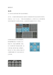
Welcome to Trident Machine ToolsLive Tool Lathe TrainingHaas live tool lathetraining•This ½ day course is designed to familiarizethe user with the theory, set-up and basicprogramming of live tooling on a Haas CNClathe.Schedule•Introductions•Live tooling types•Turret configuration•Live tooling offsets•Break•Live tooling specific G and M codes•Radial live tooling canned cycles•Axial live tooling canned cyclesCNC Slant BedLathes•Most CNC slant bed lathes consistof two axis.•X –controls diameter •Z –controls depth •These machines can perform simple turning, drilling, threading, boring, etc.•All work must be done on the centerline of the spindle.4CNC Lathes with Live Tooling•Live tooling is the ability toadd milling operations to alathe.•Done by adding driven toolsthat can be bolted on theturret of the CNC lathe.•Tools will not be as powerful asa CNC mill, but reduce thenumber of set-ups needed tocomplete a part.•Tools will enable turning andmilling in one set-up.5Types of Live Tooling•Radial tools•Hold the cutting tool parallel to the face ofthe turret.•Designed to work on the diameter of thepart performing operations:•Milling•Drilling•Tapping6Types of Live Tooling•Axial tools•Hold the cutting toolperpendicular to the face ofthe turret•Designed to work on theface of the part performingoperations•Milling•Drilling•Tapping7Base Mount Turret (BMT)•The base mount turret provides extra-rigidmounting for turning and boring tools toimprove cutting performance, and offersadditional tool clearance when working with atailstock.•All tools (static or driven) need a holderinstalled to be attached to the turret.•When loading live tooling, the tools should beinstalled in the active tool position.Types of Live Tooling•Options:•Typical live tooling holdershave a 1:1 gear ratio.•The following holders can bepurchased:•High Torque-1.5: 1 ratio•Reduced RPM, increasedtorque•High Speed -1:3 ratio•Increased RPM, DecreasedTorque•Compact Size•Adjustable Angle9C Axis•The lathe spindle becomes a rotaryto be utilized by the live tooling.•This is a true rotary which canperform simultaneous cutting.• C axis enables positioning for livetooling .10Y axis•With live tooling and a C axis rotation, machinists can makecuts on the centerline of the part.•What if we want to make cuts off the centerline of the part?•The Y axis can be added to the lathe to move the turretperpendicular to the x axis.•The Haas lathes have the ability to travel +/-2.000” from spindlecenterline.•This allows features like the following to be machined:•Flats•Bolt circles on the diameter•Holes of centerline11Haas Automation Inc. “Y axis Motion." Lathe Operator's Manual.N.p.: Haas Automation Inc., 2014. 255. Print.Axial Tools•The driven tools on the Haas lathes are mounted in the VDI tool holders1212Photo Source: Exsys Tool. N.d.Web. 29 January2015.</images/catalog/archive/haas-tooling-catalog.pdf>Axial Tool Offsets •Axial tools are offset similar to turning tools:•The Z offset can be set by touching off the face of the part.•The X offset can be set by touching the tool off on the outside of the part, then adding the diameter of thetool and part to the offset.113Radial Tools•Like axial tools, radial tools are set-up in theturret.•These live tooling holders have many types ofholders that can be used:•ER collets•Endmill holders•Shellmill holders•Tap holders14Photo Source: Exsys Tool. N.d.Web. 29 January2015.</images/catalog/archive/haas-tooling-catalog.pdf>Radial Tools•Radial tools are offset opposite theaxial tools:•To set Z offset : touch the diameterof the cutting tool off the face ofthe part.•To set X offset : set end of theendmill off the outer diameter of the part, then subtract the diameter from the offset.•The coolant line of the tool shouldalso be set while doing the tool offsets.15Coolant should be adjusted herewhen setting the tool up.Photo Source: Exsys Tool. N.d.Web. 29 January2015.</images/catalog/archive/haas-tooling-catalog.pdf>Live Tooling Geometry Offsets•Both radial and axial live geometry offsets can be set with thetool setter.•Like regular turning tools, VPS can be used to set the tooloffsets.Live Tooling Geometry Offsets•After selecting VPS, enter the live tools option,then enter manual.•Manual tool setting is the only option forsetting live tool offsets.Live Tooling Geometry Offsets •After entering the manual offset page, theorientation of the tool needs to be established.•A-axial tool offset•R-radial tool offsetLive Tooling Geometry Offsets•In this case, radial has been chosen. Thisbrings up the prompt fields specific to theradial tool.•The tools diameter and tip informationwill need to be entered.•If these are improperly entered, thetools offsets could be set wrong.Live Tooling Geometry Offsets•F2 can be used to lower the tool probe.•Selecting an axis and then pressing hand jog allows the user tohand wheel the tool to the probe without leaving the screen.•After the tool is in place, F4 can be used to output the code. Inthis case, it is output to MDI.Live Tooling Geometry Offsets•With the program in MDI, the probe down, and the tool inposition, the program is ready to run.•It is important that the live tool is spinning the opposite of thetools cutting direction.•If not, the tool could grab the tool probe with contact is made.Live Tooling Geometry Offsets•The geometry offsets for the live tools are entered into theoffset page automatically.Starting the LiveTooling•M133 –Live Tool Forward•P sets the speed•M133 P3000 –would turnthe tool on at 3000 RPM•M134–Live Tool Reverse•M135–Live Tool Stop23C Axis Engagement •New Codes:•M154 –C axis engage•The C axis must be engaged tolocate and position thespindle.•M155 –C axis disengage•The C axis must be disengagedbefore using the spindle athigh RPM.24Plane Selection•Different planes can be used tomake different canned cycles andmilling tool paths work correctlyon a live tooling lathe.•Drill or Mill–refers to face work oraxial work on a live tooling lathe.•Cross Mill or Cross Drill–refers towork on the OD or radial work on alive tooling lathe.25Plane Selection •G17, G18, G19•What are these codes?•G17 –XY plane•G18 –XZ plane•G19 –YZ plane31Plane Selection•What do these planes mean?•Plane selection (G17, G18, G19) determines the main plane of work.•Think of these planes as axis selection:•G17-the Z axis positions and the main cutting axis would be X and Y .•G18-the Y axis positions and the main cutting axis would be X and Z.•G19 -the X axis positions and the main cutting axis’ would be Yand Z.32Productivity Inc., 2012. 10. Print.G17 –Axial Milling•G17is used when XY milling is takenplace.•G17is also used with G112•G112can convert XY moves toXC moves .•This means a milling toolpathcould be converted to XC moves.•G112 is used when a live toolpath needs to go beyond the Xaxis centerline but will not reach.28G18 -The Default•The turning, drilling and boring for the part would all happen with the G18 plane.•G18could also be used for the XC milling for the slot on the front face.•G18is the default for slant bedlathes.•All of the typical OD and IDturning will happen in the XZplane.•These are the main axes ofthe machine.•XC milling also happens withG18active.29G19 –Radial and Cross Drilling •G19would be used for millingthe flat on the OD of the part.•G19would also be used when drilling the four holes on the flat of the part.•G19is used with all radial andcross drilling toolpaths.•G19would also be used withany facing or millinghappening on the OD the ofpart.30G17 Plane Selection GuideCycle Description FeedrateXY AXIS MILLING MANUAL FACE PROGARMMING G98G112CARTIESAN TO POLAR G9831G18 Plane Selection GuideCycle Description FeedrateG81SIMPLE DRILLING G98G82SIMPLE DRILL W/ DWELL G98G83DRILL W/ PECK G98G95RIGID TAP G99G186RIGID TAP LEFT HAND G99X-C MILLING FACE MILLING G9832G19 Plane Selection GuideCycle Description FeedrateG241CROSS DRILL G98G242CROSS DRILL W/ DWELL G98G243CROSS DRILL W/ PECK G98G195RIGID TAP G99G196RIGID TAP LEFT HAND G9933Face and Axial Drilling•Drilling the three holes on the face of thepart can be done with the regular G80series drilling canned cycles.•The part will be programmed without apeck because of the depth.34Face and Axial Drilling•G81is programmed the same way it wouldbe on a mill or a lathe.•Note: A “C”value can be used as a positionmove during a canned cycle.•The depth is controlled by Z.•The plain needs to be set with G18.35Face and Axial Drilling•If G82is used, a P value needs to beentered for a dwell after the depth isreached.•If G83is used, a Q value needs to beentered to specify the peck amount.36G95 Live tooling rigid tap (face)•G95Live Tooling Rigid Tapping is an axial tappingcycle similar to G84Rigid Tapping in that it usesthe F,R,X and Z addresses. However, it has the following differences:•The control must be in G99Feed per Revolution mode in order for tapping to work properly.•An S(spindle speed) command must have been issued prior to the G95.•The X Axis must be positioned between machine zero and the center of the main spindle, do notposition beyond spindle center.•G95 C45. Z-0.5 R0.5 F0.05 (Tap to Z-0.5)•*C-C-Axis absolute motion command (optional) F-Feed RateR-Position of the R planeS-RPM, called prior to G95W-Z-axis incremental distanceX-Optional Part Diameter X-axis motion command*Y-Y-axis motion commandZ-Position of bottom of hole* indicates optionalG186 Reverse Live tooling rigid tap (face)•Similar to G95 but used for tapping left hand threads. The same rules apply to G186 as G95:•The control must be in G99Feed per Revolutionmode in order for tapping to work properly.•An S(spindle speed) command must have beenissued prior to the G95.•The X Axis must be positioned between machinezero and the center of the main spindle. Do notposition beyond spindle center.•G95 C45. Z-0.5 R0.5 F0.05 (Tap to Z-0.5)•*C-C-Axis absolute motion command(optional)F-Feed RateR-Position of the R planeS-RPM, called prior to G95W-Z-axis incremental distanceX-Optional Part Diameter X-axis motioncommand*Y-Y-axis motion commandZ-Position of bottom of hole* indicates optionalOD and Radial Drilling•Drilling on the OD of the partcan be done with the G240series of canned cycles.•These are designed to workwith radial tool holders.•Y and Z will position the tooland X will control depth onthese tool paths.39OD and Radial Drilling•Cross drilling takes morethought and calculation for asuccessful toolpath.•The depth is controlled by Xfor these paths.•X is read by the machine as a diameter.•For this to work, more mathwill need to be done.40Where did this depth come from?Calculating Drill Depth•The flat is at a dimension of 1.700from the opposite side.•This means the flat is .300 deep•This depth needs to be doubled (.600) to find thediameter on the lathe where the holes start.•2.000 -.600 depth = 1.400•Diameter for the starting drill depth.41Calculating Drill Depth•The print states the holes are .38deep.•This is from the flat•This value will need to double (.760)•Drilling to a diameter because we areon a lathe.•To get the final drill depth, subtractthe final drill depth from the startingdiameter:•1.400 -.760 = .640 Diameter42OD and Radial Drilling•G19is used because Y and Z are thepositioning axis.•This makes X the retract axis for thecanned cycle.•If G18was used, the automatic retractwould happen in Z and result in a brokendrill.43OD and Radial DrillingRadial Drilling using G241, G242, G243:•Let’s look at drilling holeson the diameter of the part:•Use the G19plane.•A Radial live tooling holderwill be needed.•Remember that the machinestill reads diameter .•Depths and retracts stillneed to be programed todiameters and not radii.44OD and Radial DrillingRadial Drilling using G241:45OD and Radial DrillingRadial Drilling using G241:46OD and Radial DrillingRadial Drilling using G242:47OD and Radial DrillingRadial Drilling using G242:48OD and Radial DrillingRadial Drilling using G243:49OD and Radial DrillingRadial Drilling using G24350•Setting 22 is the amount to feed inX to get the same point at whichthe retract occurred.。
哈斯操控面板-加工中心

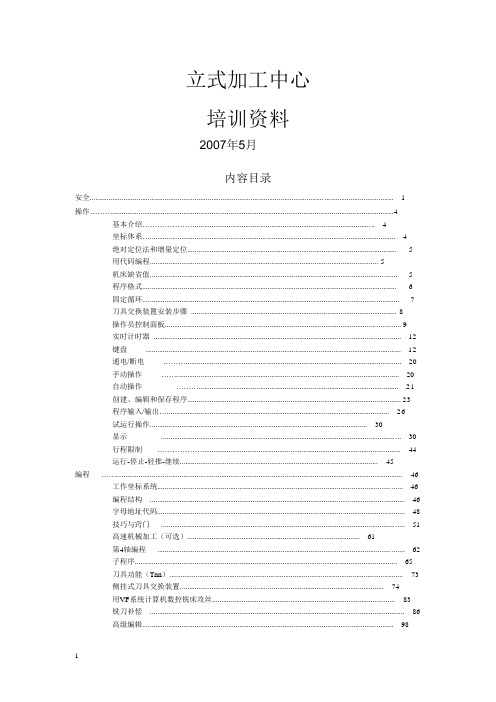
偏置键——工作坐标偏置
OFFSET (JOG) O91002 N0000
G CODE X Y Z G 52 0. 0. 0. G 54 0. 0. G 55 0. 0. 0. G 56 0. 0. 0. G 56 0. 0. 0. G 58 0. 0. 0. G 59 0. 0. 0. G154 P1 0. 0. 0. (G110) G154 P2 0. 0. 0. (G111) G154 P3 0. 0. 0. (G112) G154 P4 0. 0. 0. (G113) G154 P5 0. 0. 0. (G114) G154 P6 0. 0. 0. (G115) G154 P7 0. 0. 0. (G116) G154 P8 0. 0. 0. (G116) X POSITION: -9.0000 WRITE ADD/F1 SET/OFSET TOGGLE JOGGING Z AXIS HANDLE .01
POS-OPER (操作坐标系显页)
POS-OPER (MEM) O91002 N0000
输入 X, Y, Z 等键 再 按<ORIGIN> 可分别各轴清零 在手动模态: 按 X, Y, Z 进给键 再 按 <ORIGIN> 可分别各轴清零 你可输入例如: Z 3.5179 再 按 <ORIGIN> 显页则呈现其读数
哈斯操控台 立式加工中心
版本各异 排布相同
显示键 — 即使机床在运行中也可按任何的显示键
功能键
进给键
超控键
模态键
数字键
字母键
光标键
位置键:
POSITION (MEM) O91002 N0000
按 或 可呈不同显页: Operators (操作坐标) Work (工作坐标) Machine (机床原点) Dist-to-Go (剩余距离) 在 Debug 模态 可查阅 机床的原始数据
哈斯加工中心面板操作教案
多少?为什么? (4) 绘出运行程序的仿真轨迹。
精选范本
. 精选范本
2)点动(快动):I)选进给倍率键(同上)
Z 键 (选进给轴)
.01
.1 倍率键
X- Y-
II)直接按
X+ Y+
Z-
使工件接近或
Z+
远离铣刀
五.装刀,选刀。
按 JOG 或 MDI
再按主轴旁黑色按钮即可装卸刀具。
WRITE
CYCLE
按 MDI 输入 M06 T01 后按 ENTER 按 START 换刀
精选范本
WRITE ) ENTER
.
3)按 CW 键 → 正转 按 STOP 键 → 停转 按 CCW 键 → 反转
4)加速按
+10% SPINDL
E
四:手动进给
减速按
-10% SPINDL
E
1)手轮进给:I)按 HAND 键 JOG
II)选
XY
III)选
.0001 .0001
IV)转动手轮,移动工作台
5)按
PART ZERO
键
SET
七.输入程序:
1)按
LIST 键→按光标>键→输入程序号→按回车键
Hale Waihona Puke 2)按 EDIT 键 → PROG 键
3)输入程序 八.输入刀补
1)按 OFFSET 键,进入刀号 刀长 刀半径界面
2)输入刀补值 按 F1 键替换原有值,按回车键在原有值上累加
哈斯CNC 3-轴机器到4或5轴机器的转向与索引器转向与索引器说明书

SOLUTIONS
rotary tables and indexers make 5-axis machining easier than ever, allowing you to reduce or totally
eliminate multiple setups, and easily handle multi-sided parts.
versatile fixtur table models
SMALL
HRT100 HRT160 HRT160SP HRT160SS HRC160 HRT160-2 HRTA5
MEDIUM
HRT210 HRT210SP HRT210M HRT210HT HRT210SS HRT210-2 HRTA6 HRT310 HRT310SP HRT310SS
TILTING ROTARY
TRT70 TRT100 TRT160 TRT210 TRT310
TILTING INDEXER
T5C T5C2 T5C3 T5C4
The product that started it all
Gene Haas founded Haas Automation in 1983 to manufacture the machine tool industry’s first fully programmable collet indexer – the Haas HA5C. Needless to say, it was a complete success. Today, Haas offers more than 40 different highproductivity rotary products to help you succeed.
HASS机床操作技巧
操控技巧编辑关于如何充分利用哈斯CNC机床的控制提示。
多年来,只有拥有哈斯设备的设备与操作员才清楚哈斯CNC机床的使用非常简单,但现在这一点已广为人知。
一项独立的市场调查显示,业界的专业人士将哈斯控制设备列为最具用户友好特点的设备。
这里我们将为您展示其中的一些重点。
在哈斯控制设备的不同页面浏览时,使用最频繁的莫过于光标箭头以及为了在设置页面中查找机床设置,您只需在输入缓冲器中输入设置编号,然后按下向下箭头。
很明显,PAGE UP/ DOWN按键可用于在前页或者后页之间切换。
•PRGRM页面显示当前(活动)程序。
•POSIT显示4种不同的位置页面,以显示真实定位以及参考定位。
•轻松管理刀具、工件以及磨损坐标。
•CURNT COMDS页面中的上/下页按键可显示完整的机床信息列表,包括活动的程序。
•机床通过ALARM页面将信息发送给操作员。
•您可将自己的信息公布在MESGS页面上。
•哈斯服务技术人员使用“参数及诊断”页面。
•SETNG页面列出机床设置(可根据需要进行更改),GRAPHICS页面可用于避免碰撞。
•HELP/CALC页面可提供解答。
PRGM/CONVRS页面程序检查-在PRGRM页面中,程序检查功能可通过光标浏览,在显示屏幕右侧查看活动的程序,还可在屏幕左侧查看该程序的运行情况。
要打开程序检查功能,按下F4即可(必须在MEM模式中)。
背景编辑-该功能可用于从PRGRM页面中,在程序运行时编辑程序(在MEM模式中)。
输入您希望编辑的程序编号(Onnnnn)并按下F4。
此后,您可对现有程序、新程序甚至正在运行的程序执行简单的编辑(插入、更改、删除以及撤消)。
但是,对正在运行的程序进行编辑只有在使用M30或复位功能结束程序循环后才可生效。
位置页面DIST-TO-GO页面上的Quick Zero – 您可使用Distance To Go屏幕快速归零位置页面,以便执行参考运动。
在HAND JOG模式以及位置页面中,按下任何操作模式按键(EDIT, MEM, 等等),然后返回手轮缓进。
哈斯(Haas)CL-1型号CNC纵轴机械工具说明书

Automate Your
Turning Center Production
CL-1 Bar Feeder
Boost throughput and automate small-parts production on your CL-1 Chucker Lathe with our fully integrated pneumatic bar feeder. The CL-1 Bar Feeder automatically loads 0.25" (6.35 mm) to 1" (25.4 )diameter bars, and is available in two sizes to handle either 40" (1 m) or 72" (1.8 m) long bars for extended production runs and unattended operation.
AXIS MOTORS Max Thrust X Max Thrust Z
SPINDLE Spindle Nose Drive System Max Rating Max Speed Spindle Bore ø
TOOLING Tooling
11.0 in 4.95 in
279 mm 126 mm
4.0 in 5.0 in 1.00 in
• Easy-to-use interface in the Haas control • Simple bar loading procedure • Available to handle either 40" (1 m) or 72" (1.8 m) bars • Fully integrated automation solution
哈斯haas加工中心操作手册
立式加工中心培训资料2007年5月内容目录安全 (1)操作⋯⋯⋯ (4)基本介绍⋯⋯⋯⋯⋯⋯⋯ (4)坐标体系⋯ (4)绝对定位法和增量定位 (5)用代码编程 (5)机床缺省值 (5)程序格式 (6)固定循环 (7)刀具交换装置安装步骤 (8)操作员控制面板 (9)实时计时器 (12)键盘 (12)通电/断电⋯⋯⋯ (20)手动操作⋯⋯ (20)自动操作⋯⋯⋯ (21)创建、编辑和保存程序 (23)程序输入/输出⋯ (26)试运行操作 (30)显示 (30)行程限制⋯⋯⋯⋯⋯⋯ (44)运行-停止-轻推-继续 (45)编程⋯⋯ (46)工作坐标系统 (46)编程结构 (46)字母地址代码 (48)技巧与窍门 (51)高速机械加工(可选) (61)第4轴编程 (62)子程序 (65)刀具功能(Tnn) (73)侧挂式刀具交换装置 (74)用VF系统计算机数控铣床攻丝 (83)铣刀补偿 (86)高级编辑 (98)VF系列操作人员手册G代码(预备功能) (105)M代码(各种功能) (151)设置 (160)所有的铣削设备如旋转件、皮带、滑轮、高压电、噪音、压缩空气等均有危险存在,所以在使用CNC备及其组件时,为避免人身伤害及机械损坏,必严格遵守相应的安全守则。
操作安全必读‹ 只有经过授权的人员方可使用本机,未经培训人员在使用机床时可能对人身及机床造成伤害以及由于不正确的操作造成的问题不属保修范围内。
‹ 操作前请认真检查零配件及刀具,所有损坏的配件和刀具应当由专业人员修理或替换。
一旦有部件显示异常,不要操作,应及时联系您的车间质检人员。
‹ 操作机床时使用合适的眼、耳保护装置。
推荐使用ANSI认证的护目镜和OSHA认证的耳罩。
‹ 操作机床时一定确保其门关闭,门已正确互锁,旋转的刀具可能造成严重的人身伤害,当程序在运行中时,机床平台及主轴头能够在任一时间向任一方向做非常快的移动。
‹ 急停按钮(Emergency Stop)是在控制面板上的一个红色按钮,按下后即刻停止机床伺服电动机、换刀、冷却泵的所有运动。
- 1、下载文档前请自行甄别文档内容的完整性,平台不提供额外的编辑、内容补充、找答案等附加服务。
- 2、"仅部分预览"的文档,不可在线预览部分如存在完整性等问题,可反馈申请退款(可完整预览的文档不适用该条件!)。
- 3、如文档侵犯您的权益,请联系客服反馈,我们会尽快为您处理(人工客服工作时间:9:00-18:30)。
预热主轴 Spindle Warm Up
5. 按绿色的“CYCLE START(循环启动)”键。 Press the green “CYCLE START” button to run.
13
从USB导入程序 Loading a Program into Memory From USB
1. HASS机器本身内存较小,程序可以通过远程连接或者从USB记忆卡传送 到机器上。按下“LIST PROG(程序清单)”按键。 Programs can be run remotely from a server or locally from a USB memory stick. The Haas machine does not contain internal memory for cutting programs. Press “LIST PROG” key.
26
重启机器和继续按照程序工作
Restart the Machine and Continue with Program
3. 按“CYCLE START(循环启动)”键使机器恢复工作。 Press green “CYCLE START” button to resume.
27
使用对刀仪设定刀具长度
Байду номын сангаас24
重启机器和继续运行程序
Restart the Machine and Continue with Program
1. 检查待机状态下主轴的方向,然后关门,根据需要按“CW/FWD(正 转)”或者“CCW/REV(反转)”使主轴正转或反转。 Close door, and press “FWD” key for spindle forward or “REV” for spindle reverse depending on the direction when you stopped the spindle.
19
运行程序
Run the Selected Program
1. 要运行新程序时,按“25% RAPID(速度25%)”键使快速移动速度降 低25%,有助于保护机器,避免钻机。 Press the “25% RAPID” key to slow the cutter. This is a safety measure to prevent damage to the equipment when starting a new program.
5. 按“SELECT PROG(选择程序)”键。 Press “SELECT PROG” key.
18
从USB导入程序 Loading a Program into Memory From USB
显示屏上会显示程序内容。如果程序内容背景色是蓝色,按两次“MEM (记忆)”按键使其转换为白色。只有当程序内容背景色为白色时,才表 示程序即将启动。 The program will appear in the upper left window of the display screen. A white background means the program is ready to run. If the background is blue, press “MEM” key to activate.
31
使用对刀仪设置刀具长度
Using Touch Setter to Set Tool Length
7. 按“ENTER(输入)”键。 Press the “ENTER” key.
32
使用对刀仪设置刀具长度
Using Touch Setter to Set Tool Length
8. 利用方向键在屏幕上选择刀具种类:铣刀,钻头,丝攻。选好以后, 按“ENTER(输入)”键。
8
预热主轴 Spindle Warm Up
2. 用下方向移动键在机器的窗口屏幕上选择“Spindle Warm-up(预热主 轴)”程序O02020。 Press the down arrow key to highlight the “Spindle Warm-up” program.
9
预热主轴 Spindle Warm Up
14
从USB导入程序 Loading a Program into Memory From USB
2. 按“CANCEL(取消)”按键。 Press “CANCEL” key.
15
从USB导入程序 Loading a Program into Memory From USB
3. 按右方向键,选择插入USB记忆卡。 Press the right arrow key to select USB input.
哈斯铣床操作指南
Haas CNC Mill Instruction Manual
操作之前 Before The Operation
注意:此操作指南是针对一般哈斯设备,但是不同的机器其 控制区域/屏幕显示可能会不一样。 Note: These procedures are meant for a general introduction to Haas equipment. There may be slight variations in the controller / screen displays from one machine to another.
3. 按下“SELECT PROG(选择程序)”按键。 Press “SELECT PROG” key.
10
预热主轴 Spindle Warm Up
4. 按下“MEMORY(记忆)”按键。 Press “MEM” key.
11
预热主轴 Spindle Warm Up
按下“MEM(记忆)”按键以后,左上方的窗口会显示程序,如果程序背 景是蓝色,可以按“MEM(记忆)”键两次转换为白色背景。 After pressing the “MEM” key, the program will appear in the upper left window of the display screen. If necessary, press “MEM” key twice to toggle from blue background to white background.
28
使用对刀仪设定刀具长度
Using Touch Setter to Set Tool Length
3. 按“MDI DNC(手工输入)”键进入到手工输入数据界面。 Press “MDI DNC” key to enter manual data input.
29
使用对刀仪设置刀具长度
Using Touch Setter to Set Tool Length
6
各轴归零 Zero Return All Axes
2. 按下“ALL(所有)”按钮。 Press “ALL” key.
7
主轴预热 Spindle Warm Up
1. 冷启动时,请根据以下步骤使用每分钟最大转速预热主轴。 按“LIST PROG(程序清单)”键。 From a cold start, the spindle needs to spin up to maximum RPM in a controlled procedure to avoid damaging the equipment. Press “LIST PROG” key.
4
开机启动 Start Up Procedure
3. 按“RESET(重置)”按钮。 Press the “RESET” key.
5
各轴归零 Zero Return All Axes
1. 按下“ZERO RET(归零)”按钮,关门。 Press “ZERO RET” key and close door.
22
停止程序
To Stop The Selected Program
1. 按“STOP(停止)”键使主轴停止工作。 Press the spindle “STOP” key to stop the spindle.
23
停止程序
To Stop The Selected Program
2. 按“COOLANT(冷却)”键停止冷却系统。机器停止工作以后,可打开 防护门进行检查,检查完毕以后关闭防护门,然后重新启动机器或者 继续运行程序。 Press “COOLANT” key to stop coolant, now you can open the door to check, restart the machine and continue with the program.
Using Touch Setter to Set Tool Length
1. 将刀具安装在主轴上。 2. 按住黑色的“安装”按钮直到夹钳夹紧工具。
Manually load a tool in the spindle. Press and hold black load tool release to clamp tool.
2
开机启动 Start Up Procedure
1. 在关机状态下,按绿色的“Power On(开机)”按钮,机器随之进入 启动状态,请耐心等待。 If the machine is off, press the green “POWER ON” button. This will begin a startup cycle that may take a few minutes to complete.
4. 按“PROGRAM(程序)”键。 Press “PROGRAM” key.
30
使用对刀仪设置刀具长度
Using Touch Setter to Set Tool Length