alfa laval 605分油机说明书7
船舶阿法拉伐分油机P605分离机备件目录册(中文)
Spare parts catalogue, Reservdelskatalog, Ersatzteilkatalog, Catalogue de piéces de rechange, Varaosaluettelo, Catalogue de piezas de recambio, Êàòàëîã çàïàñíûõ ÷àñòåè, Catalogo parti di ricambio, Reservedelskatalog, Catalogo de pecas sobressalentes, Êáôáëïãïó áíôáëëáêôéêùí, Reserveonderdelen-catalogusP 605Product No.881099-06-02/1Book No.577465-02 Rev. 4Contents31Read this first 52Machine bottom part 122.1 Oil filling device 142.2Brake 163Separator bowl 184Inlet and outlet device 205Motor mounting assembly 225.1 Friction coupling, 50/60 Hz 245.2Belt tightener 266Motor mounting assembly, 60 Hz NEMA standard 286.1Friction coupling, 60 Hz NEMA standard307Gravity disc 328Set of plates 349Vibration monitoring unit 3610Set of tools 3811Interlocking switch 4012Intermediate service kit 4213Major service kit 44143-years service kit 4615Tool box 4816Cross reference list 51目录前言机器底部注油装置刹车分离机分离筒进/出口装置马达安装部件摩擦联轴节,50/60 Hz皮带张紧器马达安装部件标准摩擦联轴节,60 Hz NEMA 标准比重盘成套工具振动监控单元联锁开关中修套件大修套件工具箱3年维修套件参照表成套板材451 Read this first1Read this first Check the machine unit number on the name-plate before using this catalogue Kontrollera maskinenhetens nummer på maskinskylten innan du använder katalogen Das Typenschild - ein Hinweis zur korrekten ErsatzteilnummerLa plaque de la machine, un guide pour trouver le numéro de piéce de rechange correct La placa-marca de la máquina - guía del número correcto del repuestoÔèðìåííàÿ òàáëè÷êà ìàøèíû — óêàçàòåëü ïðàâèëíîãî íîìåðà çàïàñíîé ÷àñòèLa targhetta della macchina - guida al corretto numero dei ricambiA placa do fabricante da máquina - um guia do número correto das partes sobressalentes Konekilpi - opastin oikeaan varaosanumeroonÇ ðéíáêßäá ôçò ìç÷áíÞò åßíáé ï ïäçãüò ôïõ óùóôïý áíôáëëáêôéêïýHet gegevensplaatje - een wegwijzer naar het juiste onderdeelnummerTypeskiltet - en guide til det rette reservedelsnummer前言用此备忘录前,检查铭牌上的机器单元号P 6056Safeguard your commitment to quality by always using genuine Alfa Laval spare parts.Remember, Alfa Laval cannot accept responsibility for the failure of a separator equipped with non-original spare parts. We guarantee the quality and reliability of our products.Följ ditt kvalitetstänkande genom att endast använda Alfa Laval originalreservdelar.Kom ihåg att Alfa Laval inte tar något ansvar för fel på en separator, som innehåller icke-originaldelar. Vi garanterar kvaliteten och driftsäkerheten endast hos våra egna produkter.Aus Rücksicht auf Ihr Bestreben um beste Qualität sollten Sie nur Alfa Laval Originalersatzteile benutzen.Vergessen Sie nicht, Alfa Laval kann keine Verantwortung für das Versagen eines Separators übernehmen, der nicht mitOriginalersatzteilen versehen ist. Wir garantieren Qualität und Zuverlässigkeit unserer Produkte.Préservez la qualité de vos équipments en n‘employant que des pièces de rechange Alfa Laval.N'oubliez pas q'Alfa Laval décline toute responsabilité en cas de panne d'un séparateur non équipé de pièces de rechange d'origine. Nous garantissons la qualité et la fiabilité de nos produits.Mantenga su compromiso con la calidad, al usar siempre piezas de repuesto Alfa Laval auténticas.Recuerde que Alfa Laval no acepta responsabilidad por el fallo de una separadora equipada con piezas de repuesto no originales.Garantizamos la calidad y fiabilidad de nuestros productos.S 0023621使用Alfa Laval的正品备件来保护自己的权益。
Alfa Laval产品说明书

Product scopeEVAPORATORSIn evaporator duties, a brazed plate heat exchanger (BHE) can be optimized by vary-ing the channel plate characteristics and adding a distribution system. The distribution system provides a uniform distribution of the refrigerant throughout the heat exchanger. This ensures high performance and stable superheating under variable conditions.Though designed to operate with typical heat fluxes, Alfa Laval’s distribution systems can be adapted to higher and lower heat-flux conditions as well.CONDENSERSAlfa Laval offers a range of BHEs optimized as condensers. They feature specially-designed channel plates combining different corrugation angles, pressing depths and asymmetric channels. This makes them suit-able for a wide variety of heat-pump duties – from water heaters and micro-heat pumps to residential and commercial systems.ECONOMIZERSThe small footprint and versatile configurations of Alfa Laval’s BHEs make them easy to optimize for economizer duties.OIL COOLERSAlfa Laval’s BHE series of dedicated oil coolers, DOC range, offer unparalleled efficiency for hydraulic and lube oil cooling. The extra sturdy construction is fast and easy to install due to special connectionblocks that decrease stress on the standard connection by 80%.GAS COOLERSAlfa Laval is leading the development of new technologies for green cooling with natural refrigerants such as CO 2 and propane. Alfa Laval offers the widest range of high-pressure heat exchangers, which are not only more efficient, but also more reliable as well as safe for the environment and the people working around them.Alfa Laval Partner AcademyAs an Alfa Laval partner, you get access to a highly specialized learning centre backed by the resources of a global market leader. Our online or classroom training programs will boost your sales andservice proficiency up to its full potential.Three innovative solutions that break barriersDYNASTATIC DESIGN / FLEXIBILITYThis breakthrough production method gives you complete freedom to design the perfect refrigerant distribution system for your products. Whatever placement, size and number of distributors you want, we can produce it.Alfa Laval offers product specialists within applications such as• Air conditioning (chillers, absorption chillers and VRFs)• Heat pumps • Boilers• Solar heating• Domestic hot water • Process cooling • Fuel cells• Combined heating and power • Air dryers• Air compressors • Oil cooling• Transport refrigeration • Wind power• Vending machines • Engine cooling• Engine oil and fuel filtration • Heat recovery• Industrial refrigeration • Commercial refrigerationPartner with Alfa Laval to become best in classWith our unique wealth of experience, our dedication to finding innovative new heat transfer solutions with greater efficiency and lower energy consumption, and our global manufacturing and distribution network, Alfa Laval is your ideal partner.Growing our businesses together Becoming an authorized Alfa Laval distribution partner provides you with tools and support that aid in growing your business from new and existing customers.Support for competitive powerAlfa Laval Anytime is our eBusiness portal for partners. Find, calculate, customize and order your Alfa Laval products with just a few simple clicks, 24/7. The tool is always up to date and provides real-time stock count as well as track-and-trace functionality.The Alfa Laval Product guideThe online product guide helps you or your customers to quickly find the right heat exchanger at the right capacity within 5 clicks. All products are available for immediate shipping.Alfa Laval offer various levels of support depending on the scale of your business, how closely you wish to work withAlfa Laval and your ambitions for the future. Each level boosts your business by offering tools and tailored support for your day-to-day work. We offer a variety of training programs, sales-supporting web tools, marketing materials, and much more.We offer you product and application knowledge with a commercial approach, hands-on demonstration of technical features and analysis of specific sales points.A brazed plate heat exchanger (BHE) is very compact compared to other heat exchangers for similar applications, meaning less refrigerant is needed. AlfaNova is a range of fusion-bonded, all-stainless-steel heat exchangers. They are ideal in situations involving media that is corrosive or very sensitive to contamination of copper or nickel.All BHE units are pressure tested and labelled to comply with all major industry approvals (PED, UL, Chinese PV , KHK, KRA, and CRN). They are also leak tested with helium to ensure that every unit is gas tight.Alfa Laval also offers the widest range of AHRI certified heat exchangers which means that performance is guaranteed by an acclaimed third party global HVAC organization.Alfa Laval offers a complete range of brazed and fusion bonded heat exchangers.Please note that the table is a reference. Always check actual designs and dimensions before order.** AN-XX is a the AlfaNova range of fusion-bonded, all stainless steel heat exchangers.Alfa Laval can optimize the BHEaccording to specific applications and system requirements. Each optimized heat exchanger is unique to thecustomer, with a unique article number. Customers can be safe in the knowledge that Alfa Laval uses all its know-how to optimize their products.Continuous innovation and productdevelopment are ensured by Alfa Laval’s in-house laboratories available at all production sites. All developments and solutions are validated before being offered to customers.The Alfa Laval advantage。
Alfa laval 阿法拉伐分油机说明工作原理详解S-type Chapter4, bowl function

• If back pressure increased?
– Oil level inwards – Interface outwards – Water level inwards – Paring tube inwards
• If back pressure decreased?
Oil/water back pressure, tube position, Appendix 4
• Water paring chamber
– Low oil back pressure
– gives a large diameter water ring
Chapter 4. bowl function
– Displacement volume based on calibration of water flow at first start-up.
Chapter 4. bowl function
Inside the bowl at discharge -4
• Displacement continues • Paring tube moves in
Chapter 4. bowl function
question
• Which other separator for
Marine and Diesel use has the oil paring disc inside the top of the disc stack?
MSPX
Chapter 4. bowl function
Inside the bowl at discharge -6
alfa laval 605分油机说明书9

P-type Separation SystemAlarms and Fault FindingPrinted Book No.Feb 2011 1810898-02 V 5Alfa Laval reserves the right to make changes at any time without prior notice.Any comments regarding possible errors and omissions or suggestions for improvement of this publication would be gratefully appreciated.Copies of this publication can be ordered from your localAlfa Laval company.Published by:Alfa Laval Tumba ABMarine & Diesel EquipmentSE - 147 80 T umbaSweden© Copyright Alfa Laval Tumba AB 2011.Original instructionsContents1810898-021 Alarms (2)1.1Alarm Functions ...............................21.2Reading Alarm History List ...........21.2.1Alarm message explanation:..................31.3Alarm Reset .......................................31.4Abnormalities not displayed (4)2 Display Alarms and Actions .........53 Alarm Tests (18)1Alarms1.1 Alarm FunctionsThe alarm system is designed to ensure a safe separation system.All alarms are shown on the operator panel display, and most of them are complemented bylight emitting diodes (LEDs).The alarms are displayed in order of occurrence.1.2 Reading Alarm HistoryListTo read the stored list of alarms, proceed as follows:•Push ‘Enter’.•Push ‘+’ until ‘End’ is displayed.•Push ‘Enter’ and ‘+’ at the same time.•Push ‘+’ repeatedly until ‘AL list’ is displayed.•Push ‘Enter’.•Go through the list using the ‘+’ pushbutton until ‘End’ is displayed.•Push ‘Enter’.•Push ‘+’ repeatedly until ‘Exit’ is displayed.•Push ‘Enter’ to return to normal display.21810898-021810898-0231.2.1 Alarm message explanation:1.3 Alarm ResetW A R NI N G!Breakdown hazardNever reset an alarm without first finding and remedying the cause.It is possible to reset the system withoutremedying the cause, but the alarm signal will be repeated.C A U T IO N!Risk of injuryNever return to the operator panel to acknowledge or reset an alarm if doing so is by any means hazardous.The display shows:Alarm no. 5Alarm number0:13This alarm occurred 13 minutes ago.Feed pressure low Type of alarmP1 60Parameter Pr 1 was set to 60 minutes.00:02:13The alarm was reset after 2 minutes 13 seconds.G 001648AG 001649A1.4 Abnormalities notdisplayedThere are some abnormalities not shown on thedisplay. Below are listed the most common:Smell•Normal occurrence during startwhile the friction blocks areslipping.None.•Oil level in oil sump too low.Check oil level and add oil ifnecessary.Noise•Height position of paring disc isincorrect.Stop the separator, measure and adjust the height.•Bearing(s) damaged or worn.Renew all bearings.•Improper bowl assembly Check and reassemble. Unsatisfactory separation result•Incorrect separationtemperature.Adjust.•Throughput too high.Adjust.•Disc stack is clogged.Clean disc stack.•Sludge space in bowl is filled.Clean and reduce the timebetween sludge discharges.•Bowl speed too low.Examine the motor and powertransmission for correct frequencyparts.Check belt and coupling pads.•Bowl rotates in wrong direction Check the electrical connectionsto the motor.Why?What to do41810898-021810898-025P-TYPE SEPARATION SYSTEM ALARMS AND FAULT FINDING 2 DISPLAY ALARMS AND ACTIONS2Display Alarms and Actions10991717171311131515151617787171517on page1616141411121514171516151310131710171712on page2 DISPLAY ALARMS AND ACTIONS P-TYPE SEPARATION SYSTEM ALARMS AND FAULT FINDINGon page1317861810898-021810898-027P-TYPE SEPARATION SYSTEM ALARMS AND FAULT FINDING 2 DISPLAY ALARMS AND ACTIONSW A R NI N G!Disintegration hazardsIf excessive vibration occurs, stop separator and keep bowl filled with liquid during rundown.The cause of the vibration must be identified and corrected before the separator is restarted.•Sludge remaining in part of the bowlDismantle, clean and check the bowl before restart. See Service Manual.W A R NI N G!Disintegration hazardThe separator bowl must bemanually cleaned before starting up again.•Bowl wrongly mounted•Disc stack compression incorrect •Bowl assembled with parts from other separators Check assembly. See ServiceManual.•Height position of paring disc is incorrect. Stop the separator, measure and if necessary adjust the height.•Bowl spindle bent.Renew the bowl spindle.•Bearing(s) damaged or worn.Renew all bearings.•The frame feet are worn out.Renew the frame feet.•Spindle top bearing spring broken.Renew all springs.• Frequency deviation more than + 5%Check power supplyWhy?What to do2 DISPLAY ALARMS AND ACTIONS P-TYPE SEPARATION SYSTEM ALARMS AND FAULT FINDING81810898-02• Sludge remaining in part of the bowlDismantle, clean and check the bowl before restart.W A R NI N G!Disintegration hazardThe separator bowl must bemanually cleaned before starting up again.•Bowl wrongly mounted•Disc stack compression incorrect •Bowl assembled with parts from other separators Check assembly. See ServiceManual.•Height position of paring disc is incorrect. Stop the separator, measure and if necessary adjust the height.•Bowl spindle bent.Renew the bowl spindle.•Bearing(s) damaged or worn.Renew all bearings.•The frame feet are worn out.Renew the frame feet.•Spindle top bearing spring broken.Renew all springs.•Sensor or cable damagedReplace sensor. If no spare sensor available, set parameter Fa 16 = 0.0 to be able to run the system.Why?What to do•High power (net) frequency Check power supply before restart.•Incorrect transmission parts (50Hz belt pulley and belt for 60Hz power supply).W A R NI N G!Disintegration hazardStop and change the belttransmission to suit the power supply frequency.•Slipping belt Change belt.•Worn coupling pads Check / change pads.•Speed sensor faulty Check speed sensor•Bowl not properly closedCheck closing water supply (valve SV 16).Check bowl operating system for leakage.Check nozzle.•Bowl not properly assembled Check that the lock ring is in place.•Low power net frequency Check power.•Motor failure.Repair the motor.•Bearing(s) damaged.Renew all bearings.•Incorrect transmission parts (60 Hz belt pulley and belt for 50Hz power supply).W A R NI N G!Disintegration hazardStop and change the belttransmission to suit the power supply frequency.Why?What to do•Sensor or cable damaged Replace sensor. If no spare sensoravailable set parameter In 6 = Noto be able to run the system. •Pump has not drained the tank Check the pump function.•Separator coupling slipping Check the coupling.•Belt slipping Check the belt.•Height position of paring disc isincorrect.Stop. Check and adjust the height.•Motor failure Repair the motor.•Bearing(s) damaged or worn.Renew all bearings.•Separator start button not pushed.Push start button.Why?What to do•Emergency button pushed Remedy cause for pushing button.Reset push button.•Steam supply valve faulty Investigate cause and remedy.•Faulty triac module(s) in the power unit or faulty controller in the control unit. (electric heater)If relay K11 is on:Disconnect X12:10.If the temperature is falling, replace the control module in the control unit.If the temperature is not falling, replace the triac module(s).If relay K11 is off, but contactorK12, K16, or K17 is on, and the temperature is not falling:Check if power is supplied from the control unit to the contactor which is on (X12:6 - X12:12, X12:7 - X12:12 , X12:9 - X12:12). If it is, replace the control module in the control unit.•Broken wiring or defective heater resistance, or faulty controller in the control unit.Check adjustment of P and I functions in the control unit.If contactor sequence correct:Check wiring and heater resistance of each block or heater element. See EHM heater component booklet.If contactor sequence not correct:Replace the control module in the control unit.Why?What to do•Heater clogged•Steam supply insufficient•Steam trap faulty•Steam supply valve faultyInvestigate cause and remedy.•Faulty fuses or burned contactors(electric heater)Check and renew broken fuses. Reset overcurrent protection (applicable for 8/7 - 24/22 kW power unit).Check wiring and contactor coils.•Broken wiring or defective heater resistance(electric heater)Check wiring and heater resistance of each block or heater element. See the Service Manual booklet.•Short circuit / broken sensor or cable. Disconnect cable at sensor. Measure resistance between 1-3. Resistance shall be within 100-142 ohms = 0-110 C / 32-230 F.Test of EPC 50 input: •Disconnect cables from sensor, (terminal X 5:1-2-3).•Move jumpers Xj1 and Xj2 upwards - from Normal to Test.(The jumpers can be found inthe upper left corner of the I/OBoard)•Indication within 50-60 C when OK.•If no spare sensor available set parameter Pr 16 = 0, or if control sensor free, move connectionto that one.Why?What to do•Short circuit / broken sensor or cable. Disconnect cable at sensor. Measure resistance between 1-3. Resistance shall be within 100-142 ohms = 0-110 C / 32-230 F. If no spare sensor available set parameter Pr 18 = 0. Heater is then out of function.•Pump not working •Pressure in feed line too low Check pump. Check feed line.•Feedback signal from contactor K 2 missing Check the contactor function. Input terminalX 6:5 in EPC 50.•Communication betweenseparators in series interruptedCheck the Sattbus connection.If In 6 = yesSpeed not decreased (Fa12) asdischarge feedback.If In 6 = noPT1 pressure not decreased (Pr 31)as discharge feedback.•Check setting on Fa 12 or Pr 31•Strainer in the operating watersupply is clogged.Clean the strainer.•Water flow too low.Check opening water. Valve SV 15•Hoses between the supply valves and separator areincorrectly fitted.Fit hoses correctly.Why?What to doBroken water seal due to:•Strainer in operating water high pressure side clogged, or water pressure too low.Clean strainer.Make sure that the water pressure is 200 - 600 kPa (2 - 6 bar).•Seal rings in bowl defective.Install new seal rings.•MV 10 not opening.Examine the electrical system andcorrect the fault (open circuit, lowor high voltage or dirt).•Decreased throughput Check feed pump and adjust flow.•Regulating valve open too much Adjust back pressure valve•Change over valve V1 in recirculation position Check air pressure, solenoid valve SV1 and output from EPC 50 terminal X 8:1-X 41.Bowl opens unintentionally duringoperation because:•Strainer in the operating watersupply is clogged.Clean the strainer.•No water in the operating water system.Check the operating water system and make sure any supply valves are open.•Hoses between the supplyvalves and separator areincorrectly fitted.Fit hoses correctly.•Nozzle in bowl body clogged Clean the nozzle. •Rectangular ring in dischargeslide is defective.Renew the rectangular ring. •Valve plugs are defective.Renew all plugs.•Supply valve SV15 for openingwater is leaking.Rectify the leak.• Increased throughput Check. Reduce backpressure.•Regulating valve too restricted Adjust valve•Sensor or cable damaged Replace sensor. If no spare sensoravailable set parameter Pr 10=0.0to be able to run the system.Why?What to do•No decrease in oil pressure during this timer Check function of change over valve V1.•Pipe restricted Check recirculation for restriction •Low flow Check pump and flow regulation.Check heater for fouling.•Sensor or cable damaged Check cable connectionsReplace sensor. If no spare sensoravailable set parameter Pr 14=0.0to be able to run the system.•Feedback signal from contactor K 3 missing Check the contactor function.Check input terminal X 9:1 in the EPC.• A code has been set to makeparameter changes not possibleUnlock the code.•Wrong IP address used in In 27-30Check the setting.Why?What to do•Depends on use of the input Depends on use of the input•0V in cable heater X 12:3 to EPC50 X51:4(electric heater)Check the power supply to the heater.•High temp. switch released (electric heater)Check temp. setpoint in the control unit.Check the heater and clean if necessary.When the alarm is reset, the temp. switch is also reset.•Attempt to operate remote OP Not legal when local OP is active.•Black-out has occurred with EPC in operation Check plant conditions and restart.Why?What to do•If parameters are changed automatically by "thunderstorm"type influence, alarm is given to indicate out of range.Switch EPC50 power off. MoveX J4 on I/O board to position right. Switch power on. Parameters are now all set to default values. Move X J4 back to original position. Adjust all parameter settings to correct value.•OP (Operator Panel board), I/O board or OPr (Operator Panel remote board) in EPC notworking Check cables to board or replace the board (see Change of Circuit Board in the Service Manual booklet).•Bad connection Check connection•Board faulty Replace the board•Cable errors Check cables to board or replacethe board (see Change of CircuitBoard in the Service Manualbooklet).•Optional heater board in EPC not working Check cables to board or replace the board (see Change of Circuit Board in the Service Manual booklet).•X71:2 and X71:3 are both set to0 or both set to 1Set one switch to 0, and the other to 1.•Optional vibration board in EPC not working Check cables to board or replace the board (see Change of Circuit Board in the Service Manual booklet).•Insufficient heating during start(Ti 53)Check heater function.•Alarm is displayed at standstill after emergency or vibration shut down Investigate the cause for the stop and switch the power off and then on to the EPC 50.•If Pr 25=0 the high level alarm isdisabledWarning to operator only.•If Pr 5 is used, the text in Pr 6 is displayed Take action according to what the text means (plant dependant).Why?What to do3Alarm TestsN O T EIf any parameter value is changed to activate analarm, do not forget to reset to the original valuebefore operation.Alarm message ReddiodeSequence Method Terminal Reaction Standard functionsPOWER FAILURE Start Switch power off / on duringoperationFeed pressure PT1 - HIGH PT1Start Decrease limit (Pr14)V1 offFeed pressure PT1 - LOW PT1Start Increase limit (Pr15)V1 offFeed pressure sensor PT1 -ERRORPT1Start Disconnect sensor X5:4Pump starter - FAILURE Pump Start Switch pump offOil feed - TEMPERA TURE HIGH TT Start Decrease limit (Pr16/Pr19)V1 off.Heating off. Oil feed - TEMPERA TURE LOW TT Start Increase limit (Pr17/Pr20) ordecrease Ti 53.V1offTemperature alarm sensor - ERROR TT Start Disconnect sensor X5:2V1 offHeating off.Oil back pressure PT4 - HIGH PT4Separation Increase back pressure V1 offOil back pressure PT4 - LOW PT4Separation Decrease back pressure V1 offOil pressure sensor PT4 -ERRORPT4Separation Disconnect sensor X5:6Emergency stop - BUTTON PUSHED Separation Push the button Sep.motoroff, heateroff, feed onfor 3 min,stop.Optional functionsTemperature control sensor -ERRORTT Start Disconnect X51:2Heater - FAULT (Heatpac powerunit only)Heater Start Disconnect X51:4Temperature increase - TOO SLOW TT Start Start separator and EPC butnot heater, or start systemwith Ti 53 set to 1.。
阿尔法拉瓦尔(Alfa Laval)Emmei.2高速离心分离器说明书
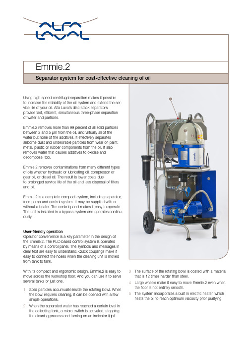
With its compact and ergonomic design, Emmie.2 is easy to move across the workshop floor. And you can use it to serve several tanks or just one.1Solid particles accumulate inside the rotating bowl. When the bowl requires cleaning, it can be opened with a few simple operations.2When the separated water has reached a certain level in the collecting tank, a micro switch is activated, stopping the cleaning process and turning on an indicator light.3The surface of the rotating bowl is coated with a material that is 12 times harder than steel.4Large wheels make it easy to move Emmie.2 even when the floor is not entirely smooth.5The system incorporates a built in electric heater, which heats the oil to reach optimum viscosity prior purifying.Separator system for cost-effective cleaning of oil1345 2Meeting your needsTo meet all your needs, Alfa Laval offers a wide range of stationary or mobile separator systems for all types of fluids. Our offering ranges from systems with capacities suitable for smaller workshops to larger systems designed to clean complex and heavily contaminated fluids.Our global organization guarantees easy start-up and, if you need a helping hand, an Alfa Laval service engineer is always close by. To support your operations further, Alfa Laval has a network of distributors and service partners who are always available to assist you.We call this nonstop performance.Technical data CapacityMax flow, 50/60 Hz 200 l/h (0.88 gpm)Sludge space0.6 l (0.16 gal)Fluids requirementsViscosity at separation temperature Max 40 cSt*Max. separation temperature 70°C (160°F)pH value6–9Electrical data Voltage 230 V or 100–230 VSingle-phase (±5%)Frequency50/60 Hz Amperage (at 230/110 V) 10/16 AWeightWithout heater 60 kg (130 lb)With heater 100 kg (220 lb)DimensionsWith heater Without heater Length 630 (25") 615 (24 1/2")Width 680 (27") 520 (20 1/2")Height1130 (45")1130 (45")* For higher viscosity oils the oil is heated to reachsuitable viscosity.Emmie.2 is delivered complete with stand, collection tank for separated water, dive tubes, hoses, service tool kit and instruction book.EFU00047EN 1705Alfa Laval reserves the right to change specifications without prior notification.A L F A L A V A L i s a t r a d e m a r k r e g i s t e r e d a n d o w n e d b y A l f a L a v a l C o r p o r a t e AB .How to contact Alfa Laval Up-to-date Alfa Laval contact details for all countries arealways available on our website at The unit is equipped with two dive tubes (left) for suction and returnof the oil. Optional is a tank filler device (right) with quick couplings.The user-friendly control panel. Just choose oil viscosity, press thestart button and the system operates without supervision.。
Alfa Laval Clara 高速分离器系列商品介绍说明书
The Clara range:gentle treatment, efficiency, low powerThe Clara range of high-speed separators is specially developed for the food and beverage industries. In developing the Clara range, we emphasized gentle product treatment, high separation efficiency and lowpower consumption.Each model has its advantagesSelection guide for the different designs available in the Clara separator range.Within the Clara range there are models of all sizes – from laboratory or pilot scale operation to models for large food or beverage plants with huge capacities. Depending on model the Clara separators are available in different designs, from non-hermetic (‘top fed’), to fully hermetic design. The Clara separators have several distinct advantages, depending on the model.Disc inletThe disc inlet enables the feed to accelerate in a very gentle way. This increases separation efficiency and minimizes foaming.Oxy-StopThe liquid seal in the separator outlet prevents oxidation of the product and loss of volatile aromas or CO 2.Fully hermetic designThe fully hermetic design is achieved by a combination of a hollow spindle inlet, a hermetic outlet provided by a mechanical seal, and a separator bowl completely filled with liquid.In addition to maximum separation effi-ciency and significantly reduced power consumption, the fully hermetic concept prevents any air-liquid interface, which otherwise is a source of foaming and food degradation.Hollow spindle designOur unique hollow spindle design ensures the gentlest acceleration of shear-sensitive particles. This leads to maximum separation efficiency and reduced power consumption at the same time.Clara 701 separatorClara 200 separator systemAlfa Laval components and systems for beverage processingHigh-speed separators Decanter centrifugesHeat exchangers, includingevaporators pasteurizers, sterilizers, etc.Membrane filtration systems Aroma recovery unitsPumps, valves, tubes & fittings,and other fluid handling components Tank cleaning componentsControl and automation systemsIts design allows for the smoothest possible feed acceleration.For the modern winemaker a Clara separator offers several opportunities to optimize the winemaking process, also from a quality point of view. The processes that need time and hands on care to get the best result, such as fermentation and maturation, should have the time and attention needed. Focus on what is important and let a Clara separator clarify the must or wine with more reliable results, in less time and with less work.With a continuously working Clara separator the use of kieselguhr filters can be reduced. This cuts costs in buying and disposal of the kieselguhr as well as the manpower needed to clean and prepare the filters.Must clarificationWith a soft press or a decanter for juice extraction there is no need to keep the must in a settling tank. Run it directly through a Clara separator and save time as well as the energy needed to cool the tank. It also requires less space.As the solids volume discharged from a Clara separator are much less than the tank bottom from the settling tank, a smaller kiesel-guhr filter is needed as well.Since must is a demanding separator application with high solids load, make sure to chose a model with highefficiency solids discharge, a feature allClara models have.Young wine clarificationWith a Clara separator its possible to stop the fermentation when you want, simply by running the young winethrough the separator. Its of course also possible to separate the wine after its been resting on the lees.Mature wine clarificationWhen the wine is ready the storage tanks can be emptied rapidly over the Clara separator, with a clear wine as result.Sparkling wineWhen second fermentation is made in a pressure tank a Clara separator can be used to remove the yeast and produce a wine that is truly sparkling clear. A reliable seal is crucial to keep the CO 2 in place.The capacities depend on the raw material to be processed and the processtechnology applied.Making quality wine in less timeWine productionGrapesTea producers use a wide variety of process set-ups for processing of their product into the varieties of different tea products available on the market. However the same basic techniques are used in making a processed tea product regardless if the customer’s end product is Ready To Drink (RTD) tea, tea powder or tea polyphenols etc.After infusion of tea raw material in hot water, the product is fed via a prefiltration and a cooling step to the clarifier to remove fine particles from the extract. In the clarification step, all modern tea producers can benefit from the high-speed separator technology, which has also proven efffective in meeting the customer’s requirements. In addition to the Clara range, Alfa Laval offers several other models to complete the range for tea customers of all application duties and capacity requirements.RTD teaWhen producing RTD tea, the de-mands on clarity of the end productare exceptionally high, especially when the end product is to be bottled in transparent PET bottles for cold serv-ing. The Clara separators are a perfect fit to this process due to maximum separation capacity and gentle treat-ment of the product, resulting in a tea with premium clarity.Tea concentrateFor tea concentrate a Claraseparator can be used to clarify the tea prior to concentration. Moreover, with the unique inlet system, a Clara separator has a perfect fit to be used after pre-concentration for removal of precipitations that occur due to pre-concentration and cooling. A Clara separator can also be used for final polishing of the tea prior to final evaporation and drying.Aroma recoveryIn the aroma recovery process the flavour components of the extract are recovered. For the removal ofsuspended solids from the extract aClara separator can be used.The capacities depend on the raw material to be processed and the processtechnology applied.Take a break with the clearest teaRTD tea processTea concentrate processClara separatorConcentrationTankBlendingPasteurizingHeat exchangerBottlingPre-filtrationFiltersHolding tankCoolingHeat exchangerCoarse filtrationCoolingTubular heat exchangerTankWasteHot waterExtractionRaw materialheat exchangerA clear advantage in beverage processingIn coffee processing the Claraseparators can be used whether the end customer is producing concentrate coffee, RTD coffee or coffee aromas. Alfa Laval’s range of coffee separators also includes models dedicated to processing of spent grounds, coffee deoiling and high density products.Coffee concentrateFor coffee concentrate a Claraseparator is placed in the process line after extraction, to remove insolubles from the coffee extract before going to evaporation. The separator minimizes or eliminates the need for more labour intensive filter equipment. With premium clarification evaporator operation times can be increased thanks to less clog-ging and fouling.RTD coffeeIn recent years, the market has seen an increase in the popularity of coffee sold in bottles and ready for consumption. In the clarification step, most modern producers use separators due to theirmany advantages. With a Clara separa-tor, a coffee producer can achieve high capacities of premium quality coffee extracts with large throughputs. Aroma recoveryIn the aroma recovery process theflavour and aromas in the coffee extract are recovered. The Clara separator can be used for removal of suspended solids from the extract.The capacities depend on the raw coffee to be processed and the processtechnology applied.Keep that premium coffee flavor and aromaCoffee productionKeeping your plant up and running at peak performance is essential for the success of your business. That boils down to support. Alfa Laval seess ervice as a lifelong commitment to optimizing your plant’s performance. This means both being on handw henever you need us as well asp roviding predictive maintenance for optimal uptime.The Nonstop Performance service offer is designed to do just that.Nonstop PerformanceOur service offer is structured into four levels of performance agreements. They range from the One Star level covering basic needs, up to the comprehensive Four Star level where we function as your long-term performance partner. You decide which level is best.Whatever level of service you need, we work with you to tailor a package that is right for you.Global service – locallyWith over 50 Service Centres worldwide manned with highly trained personnel you can be sure you’ll get the service you need – when you need it. Alfa Laval’s global spare parts distribution network is unmatched by any other supplier. That means you get parts faster and cheaper. And keep production rollinground the clock.Nonstop Performance。
Alfa Laval 全系列衛生用泵说明书
Alfa Laval is one of the world’s largest pump suppliers, offering a fl exible portfolio of centrifugal pumps, liquid ring pumps and positive pumps.Our portfolio is the result of a combination of compre h ensive pumpknowledge and the highest standards of hygiene, trouble-free operation and a truly low cost of ownership.2Performancein good handsWorking with hygienic applications is a question of care, attentionto detail and dedication to outstanding performance. Alfa Laval hasa proven track record in delivering innovative solutions for hygienicapplications based on our core technologies of separation, heattransfer and fluid handling.Superior safety, gentle efficiency and uncompromising cleanlinessare the hallmarks of our hygienic pumps, heat exchangers, valvesand automation, tubes and fittings, and separation, filtration andtank equipment. Which is why so many customers in the food,biopharm and other demanding industries put process perfor m anceand hygiene in the capable hands of our experts, sales companiesand partners worldwide.Here you will find an overview of Alfa Laval pumps for hygienicapplications. For complete technical details and productspecification , contact your local Alfa Laval supplier or visit us at3Gentle product treatment Our centrifugal pumps are renowned for their ability to move products gently and efficiently. The integrity of your product is assured, regardless whether you choose a premium or standard-duty model. Advanced hygienic designWith emphasis on featuressuch as optimized internalgeometry and profiled o-rings,our centrifugal pumps aresuitable for CIP (cleaning-in-place) and offer exceptionallevels of hygiene. All have beentested in accordance withEHEDG requirements and areauthorized to carry the 3-Asymbol.Advanced seal designMany of our pumps share thesame mechanical shaft seal,which simplifies maintenanceand spare parts inventory.Combined with the quick andeasy front-loading design, thisreduces maintenance costs,increases uptime and reducesthe cost of ownership.Easy seal conversionThe external design of ourcentrifugal pumps, as wellas the seal’s construction,is designed to make sealconversion as fast and assimple as possible. Ourpremium LKH pumps can beconverted from single toflushed or double-mechani c alseals, while our standard-dutySolidC pumps can beconverted from single toflushed shaft seals.4Centrifugal pumps Alfa Laval’s centrifugal pumps are built to perform inall areas – from process quality to overall energyefficiency. In addition to gentle product handling anda wide range of hygienic features, they provide a longand trouble-free service life that ensures low cost ofownership.Our centrifugal pump series can be divided into twocategories, premium and standard-duty.Computer-designed impellersOur centrifugal pump impellers are computer-designed and hydraulically balanced for optimum performance . Both the impellers and their retaining screws (optional) are smooth, which keeps them from accumulating product and makes cleaning more effective. Efficient performanceOur centrifugal pumps havethe optimal design for thegreatest efficiency, lowestNPSH requirement and lownoise levels. This reducesenergy cost, lowers the risk ofcavitation and provides a safeworking environment, whichenables efficient capitaliza t ionof the process.The first category comprises our various cost-effective LKH pumps, which handle spe c ializedneeds such as evaporation, high-pressure,self-priming and high-purity applica t ions. Thesecond focuses on initial cost, which includesour optimized SolidC pump series.56Premium pumpsQuiet but rugged, Alfa Laval’s LKH series of centrifugal pumps are the ultimate solution for gentle and efficient product handling. Through a combination of enlarged inlets and advanced impeller design, they offer an unobstructed product flow, very low NPSH requirements and superior hydraulic efficiency.Designed for CIP (cleaning-in-place), LKH pumps are available in capacities of up to 2200 gallons per minute (GPM) and pressures of up to 525 feet of water (227 PSI), with different versions available for specific applications.LKH performance: LKH pumps are available for capacities up to 2,200 GPM and pressures up to 525 feet of waterH (ft)T D 200-464010020030040050020040060080010001200140016001800200022002400LKH-45LKH-60LKH-70LKH-90LKH-75LKH-15LKH-5LKH-20LKH-10LKH-25LKH-35LKH-40LKH-50LKH-457LKH UltraPureLKH UltraPure pumps are high-purity pumps that meet specifications for water-for-injection (WFI) and other demanding applications. Authorized to carry the 3-A symbol, they are suitable for both CIP (cleaning-in-place), SIP (sterilization-in-place) and manual cleaning. LKH UltraPure pumps are also available with either a 20 Ra or 15 Ra finish, flushed seal kit and a comprehensive Q-doc documentation package to smooth the qualification and validation process.LKHThe LKH is a highly efficient and economical centrifugal pump range, which meets the requirements of sanitary processes for gentle product treatment, hygiene and chemical resistance. Its front-loaded design makes quick, effective maintenance possible, thereby contributing to more production time and low cost of ownership. Available in 13 sizes, the LKH features efficient drives which make it possible to optimize performance for the selected duty as well as comply with 3-A, CE and EHEDG requirements.LKH-75Designed for high flow rates with very gentle product treatment, the LKH-75 is ideally suited for high volume milk receiving required by the largest dairies. Like the entire LKH series, the LKH-75 features enlarged inlets combined with an advanced impeller design, resulting in unobstructed product flow and very low NPSH requirements. The pump has a capacity of up to 800 GPM and pressures of 180 feet of water and operates at a gentle 1800 RPM, and features low power consumption and noise emission levels. This translates to high flow rates withextremely gentle product treatment which are critical to maintain the taste and value drivers of high volume milk production.8LKH MultistageDesigned to 3-A standards and available in two, three or four-stage models, LKH Multistage pumps save space and energy by replacing up to three booster pumps in a line. Used primarily in high-pressure applications with low capacity, they deliver boost pressures up to 900 feet (390 PSI). This makes them suitable for, but not limited to, many types of filtration applications.LKH-PF High PressurePumps in the LKH-PF High Pressure series feature a reinforced pump casing and backplate, as well as high pressure internal seals and multiple heavy-duty studs. This enables them to handle inlet pressures as high as 600 PSI, making them ideal for the most demanding filtration applications. Their seals can be removed in a matter of seconds, without removal of the back plate.LKH-90The LKH-90 extends the LKH range flow rate to 2,200 GPM, making it an ideal solution for today’s high volume applications. Specifically, the LKH-90 has proven to be the pump of choice for filtration system builders. It utilizes the same front-loading seal as the LKH-75 and is available in a variety of connection types.Only one size of shaft seal is required for all LKH standard models (LKH 5–60) and SolidC (SolidC 1–4), which makes keeping the right parts in inventory simple and inexpensive. Plus, a single mechanical seal can easily be changed to SolidC 1SolidC 2SolidC 3SolidC 460504540352520155–10Frequency: 60 Hz H (ft)400Positive pumpsDesigned for low, medium and high-viscosity media, Alfa Laval positive pumps offer gentle pumping action and reliable performance which results from more than 50 years of continuous development at advanced production and R&D facilities.Our positive pump portfolio includes four ranges: SX, SRU, OptiLobe and SCPP. With its robust construction, each pump is developed for a different type of demand and meets high standards of quality and reliability. Collectively, they provide operating economy and high flexibility of use.Gentle, hygienic design With their high-precision rotors and low-shear operation, our positive pumps ensure the gentle movement of delicate products. Designed for maximum cleanability, our pumps comply with the world’s leading hygienic standards.Modular pump designModular design increasesfl exibility and component inter-changeability, reducing main-tenance time and spare partsinventory. The wide range ofsizes available enables selec-tion of the most cost-effectivesolution for your processrequirements.Universal mountingTo provide high flexi b ility whenfitting the pump into a produc-tion line, all of our positivepumps can be mounted ineither a vertical or horizontalport position.Improved drainabilityAll of our positive pumpscan be drained easily whenmounted in vertical portp osition. In the case of ourOptiLobe and SX pumps,cusps are retained in verticalconfigurations for greatere fficiency.12Easy seal retrofitThe seals of our positive pumps are designed for quick and simple upgrading. Our broad range of seals includes many seal types and configu-rations, which can be tailored to your need and application. Heavy-duty gearboxconstructionThese pumps have a cast irongearbox with heavy-duty taperroller bearings and torquel ocking assemblies for easymaintenance and highr eliability.CIP and SIPOur positive pumps are idealfor both CIP (cleaning-in-place) and SIP (sterilization-in-place) applications.Standards and approvalsAll of our positive pumps arecompliant with CE directivesand the EHEDG, 3-A andFDA hygienic standards. Inaddition, our SX and SRUpumps can meet ATEXrequirements for use inexplosive environments.1314SXThe SX is Alfa Laval’s premium positive pump and is designed for use in sensitive and ultra-clean applications. With optimized pump head geometry and multi-lobe rotors, SX pumps ensure low-shear operation with minimum pulsation. This makes them the best choice for maintaining the integrity of delicate products.SX pumps feature front-loading mechanical seals, and low-profi le rotor nut for the highest level of hygienic sealing and enhancing cleanability. Options available for mechanical and/or electro-polishing to achieve higher surface fi nishes up to 0.5 Ra as well as 3.1 material traceability.OptiLobeThe OptiLobe is Alfa Laval’s standard duty positive pump intended for general applications. Available in an optimized range with fewer options, OptiLobe pumps combine cost-effective simplicity with Alfa Laval quality and reliability. OptiLobe pumps feature a paint-free design with front-loading seals and tri-lobe rotors. They are the latest example of Alfa Laval’s leadership in innovative design and advanced manufacturing processes.SRUThe SRU is Alfa Laval’s core positive pump with extensive options, materials and ability to handle a wide range of temperatures and pressures. This makes it the ideal solution for the most demanding of applications.Among the many options are saddles and jackets for heating and cooling of the pump head, rectangular inlet for pumping high viscosity fl uids and a wide selection of standard seals, including proprietary seals to suit most applications. In addition, you can choose from tri-lobe or bi-lobe rotors depending on the application.15Pumps can be supplied as bareshaft for mounting locally in the process line or within a skid. Alternatively, Alfa Laval offers the units fully motorized using robust, reliable and effi cient geared drives, which can be designed for direct drive or for speed control.The rigid base plate ensures accurate alignment of the pump and drive and is available in stainless steel for hygienic environments.Other options include ball feet for raising the unit above the fl oor level to provide access for cleaning.MotorizationSCPPThe SCPP is a circumferential piston pump designed for transporting very low viscosity products in applica t ions that require medium to high discharge pressures. The piston design offers low shear with low pulsation and minimizes damage to product and bruising of solids.Two SCPP ranges are available: the SCPP1 specifi cally designed for quick and easy strip-clean type processes and the SCPP2 where CIP (cleaning-in-place) may be utilized.This complete portfolio of positive pumps enables Alfa Laval to offer the most effective solution, whatever the application.All you need to know ...The Alfa Laval pump handbook. Computer-Aided Selection (CAS) software.In st ru ct io ua lQ-doc.n M anManual de instrucciones l de instruccionesky 優質幫浦000000Comprehensive documentation in multiple languages.18With this foundation, we work closely with our channel partners to help companies extract the most value from raw materials, minimize waste and emissions, and deliver safe and hygienic products. Ultimately, our ambition is to help companies supply quality products to consumers at competitive prices.Alfa Laval has served as the standard bearer for the production ofh ygienic products since Gustaf de Laval invented the centrifugals eparator to separate cream from milk more than a century ago. That same ingenuity is applied to all our hygienic components and solutions that safeguard the flavour, texture and appearance of food, dairyp roducts, beer and other beverages.For the pharmaceutical, biopharm and personal care industries, ourc ontributions not only entail hygienic design and superior performance but comprehensive documentation and solutions that are easy tov alidate. Which in turn raise the quality, clean l iness and uniformityof the final products.Safeguarding hygienic applications requires entrusting your processes to the safe, competent care of a reliable partner.With Alfa Laval you are in good hands.Handling your hygienic processing needsOptimizing the performance of hygienic processes is a challenge best met with expertise. Alfa Laval expertise is the result of years of accumulated knowledge and a comprehensive research and development program.Working locally ona global scaleAlfa Laval brings you the advantages of a worldwide organization supported by a strongnetwork of 1,500 partners around the globe. This gives you a one-stop shop for everything,including quality parts and unmatched service expertise.Trustworthy serviceGuaranteed performance, reliability and hygiene come standard withevery Alfa Laval pump. Each pump is backed by the service and supportfrom our global organization and local network of distributors, systembuilders and contractors. This gives you easy access to advancedresources and specialist knowledge about hygienic components andprocesses.Investing in quality partsThere are no short cuts to quality, especially when the integrity ofhygienic processes is at stake. That is why investing in Alfa Lavalhygienic components and solu t ions ultimately pays off.Alfa Laval parts are precision-made to ensure optimal performance.Rigorous testing in our materials laboratory under actual operatingconditions ensures that each part will uphold safety, efficiency andhygiene of your processes for the long term.Unsurpassed reliabilityIt goes without saying that an investment in quality is an investment inreliability. Alfa Laval hygienic components and solutions are designedand sized right from the start. When reinforced by maintenanceprograms and Alfa Laval parts, you are able to achieve a strongtotal cost of ownership and true peace of mind.19。
阿法拉伐中文说明书

阿法拉伐中文说明书1(共94页) -本页仅作为预览文档封面,使用时请删除本页-目录1安全说明…………………………………………………………..... 2卧螺离心机的操作原理……………………………………….....主电机………..…………………………………………….………………......后驱动系统……………..………………………………………………… ...变频后驱动(VFD)..…….……………………………………………… ..... 3操作和日常维护…………………………………………………在第一次开车前……………..………………………………………………噪声和振动…………...……...………………………………………….…开车和停车程序…………………..…………………………………………检查转鼓……..…………………………………………………………….开车前…………..………………………………………………………….检查要点………….……………….……………………………………..具有机械密封的离心机…………………..……………………………..启动离心机………………………………………..……………………….离心机停车……………………………………………..………………….监控操作……………………………………………………………………..过载………………………………………………………………………...过载的原因………………………………………………………………清理过载的转鼓…………………………………………………………振动………………………………………………………………………... ..振动开关(可选设备)…………………………………………………监测螺旋磨损……………………………………………………………...定期清洗过程………………………………………………………………..优化操作……………………………………………………………………..主电机………………………………………………………………………..变频驱(VFD)……………………………………………………………...调整转鼓速度传感器(图)………………………………………..润滑…………………………………………………………………………..主轴承……………………………...………………………………………螺旋轴承(图中的加油嘴3和4)………………………………...齿轮箱(图)………………………………………………………...维护表……………………………...…………………………………………润滑时间和维护方法……………………………………………………...表润滑表………………………………………………………….…表维护周期…………………………………………………………润滑剂型号………………………………………………………………...表润滑剂、润滑工具表……………………………………………4拆卸和组装………………………………………………………旋转组件……………………………………………………………………...拆卸转鼓(图和)…………………………………………….安装转鼓(图和)…………………………………………….拆卸大端轴颈(图)………………………………………………...安装大端轴颈(图)………………………………………………...拆卸小端轴颈(图)………………………………………………...安装小端轴颈(图)……………………………………………….拆卸齿轮箱(图和)………………………………………….安装齿轮箱(图和)…………………………………………装配新的排污口衬套…………………….………………………………主轴承…………….…………………………………………………………..拆卸大端主轴承(图)…………………………………….…………..组装大端主轴承(图)………………………………………………...拆卸小端主轴承(图)………………………………………………...安装小端主轴承(图)………………………………………………...螺旋轴承……………………………………………………….…….……….拆卸螺旋大端轴承(图)…………………………………….………..组装螺旋轴承大端轴承(图)………………………………………拆卸螺旋轴承小端轴承(图)……………………………………...安装螺旋轴承小端轴承(图)……………………………………...螺旋…………………………………………………………………………...从转鼓中拆卸螺旋(图)……………………………………………将螺旋装入转鼓(图)………………………………………………...主电机………………………………………………………………………..拆卸主电机(图)……………………………………………….…..组装主电机(图,和)………………………………….…..调紧V形皮带,皮带张力表………………………………………………变频后驱动装置(VFD)…………………….……………………………..拆卸变频驱动器(图)………….………………………………….组装变频驱动器(图)……………………………………………..5补充文档…………………………………………………………1安全说明请务必严格按照以下要求进行操作,否则会给您造成人员以及财产的损失。
alfa laval 605分油机说明书6
PA Purifier SystemSystem DescriptionPrinted Book No.Oct 2005 1810895-02 V 4Published By:Alfa Laval Tumba ABSE-147 80 Tumba, SwedenTelephone: +46 8 530 650 00Telefax:+46 8 530 310 40© Alfa Laval Tumba AB 26 October 2005This publication or any part there of may not be reproduced or transmitted by any process or means without prior written permission of Alfa Laval Tumba AB.Contents1810895-021 System Overview (5)1.1The Oil Flow .......................................51.2System Layout ..................................61.3System Components,PA 600/610..........................................81.4System Components,PA 605/615..........................................91.5System Components,PA 625/635 (10)2 The Process (11)2.1Purifying ............................................112.2Definition of Terms (12)1810895-021810895-0251System OverviewThe PA Purifier System is designed for cleaning of lubricating and fuel oils in marine and power applications and can handle the following types of oil:•distillate •marine diesel oil •intermediate fuel oil•heavy fuel oil with a maximum viscosity of 600 cSt•detergent lubricating oil •R&O lubricating oilIn the purifier process, heated oil is fed through the separator to clean the oil from solid particles and water.The system comprises:• A separator.•Ancillary equipment including a control unit.•Optional equipment such as oil feed pump, oil heating system, sludge removal kit , etc.The separating systems can be operated as single, parallel or serial systems.During the process, the cleaned oil leaves the separator through the oil outlet, separated water leaves through the water outlet, and sludge accumulates at the periphery of the separator bowl.The control unit initiates a sludge discharge at preset intervals.Sludge and water are then discharged through sludge ports at the periphery of the bowl and collected in a sludge tank.P 003716A1 SYSTEM OVERVIEW PA PURIFIER SYSTEM SYSTEM DESCRIPTION61810895-021.2 System LayoutFeed pumpFeedsseparator.Temperature transmitter (TT1, TT2)Measures the oil temperature and Pneumatically controlled change-over valve (V1)Directs the unprocessed oil to the separator, or back to the settling tank (recirculation –HeaterHeats unprocessedoil to separation temperature.SeparatorCleans the oil byremoving water and solidparticles.Solenoid valve block, waterDistributes separator opening/closing water, and conditioning water.Sludge outletinlet Oil returnPressure transmitter, oil (PT1)Measures the pressure in the oil inlet, and signals the control unit.Additional equipmentnot part of the PAPA PURIFIER SYSTEM SYSTEM DESCRIPTION 1 SYSTEM OVERVIEWClean oil outletto service tank1810895-0271 SYSTEM OVERVIEW PA PURIFIER SYSTEM SYSTEM DESCRIPTION 1.3 System Components, PA 600/61081810895-021810895-029PA PURIFIER SYSTEM SYSTEM DESCRIPTION 1 SYSTEM OVERVIEW1.4 System Components, PA 605/615X 023760A1 SYSTEM OVERVIEW PA PURIFIER SYSTEM SYSTEM DESCRIPTION101810895-021.5 System Components, PA 625/635X 023718APA PURIFIER SYSTEM SYSTEM DESCRIPTION 2 THE PROCESS 2The ProcessThe terms used in this process description areexplained in section ‘‘2.2 Definition of Terms’’ onpage 12.2.1 PurifyingA water seal is added to the separator bowlthrough the water inlet.The separator is equipped with a gravity disc,chosen according to factors such as oiltemperature, density, and feed rate. This choicedecides the position of the interface between oiland water seal.The separator does not use a paring disc to pumpout the separated water. Instead, the waterleaves the bowl via the gravity disc, and leavesthe separator through the water/sludge outlet.Process Cycle1 A specific amount of water is added to theseparator bowl to form a water seal.2The feeding of unprocessed oil to the centreof the separator bowl starts.3During the separation process sludge andwater accumulate at the periphery of theseparator bowl. Cleaned oil is fed from theseparator by the integrated paring disc.Excessive water leaves the bowl through thewater/sludge outlet to the sludge tank.4After the preset time between dischargesequences, the oil feeding stops.5Displacement water is added to the bowl. Thedisplacement water reduces the oil loss at thefollowing sludge discharge.6 A sludge discharge is initiated while thedisplacement water is still flowing.The next process cycle starts with adding ofwater for a new water seal.1810895-02112 THE PROCESS PA PURIFIER SYSTEM SYSTEM DESCRIPTION121810895-022.2 Definition of TermsPreset time between sludge discharge sequences(Parameter value)When this time has elapsed after a sludgedischarge, the next discharge is initiated.Water seal(Parameter value)Water, added to the separator bowl to prevent oil from escaping at the water outlet. Displacement waterWater, added to the separator bowl to displace the oil and ensure there is reduced loss of oil at sludge discharge.PurifierA separator that cleans the oil from water and sludge with continuous evacuating of separated water.。
船用分油机中文说明书

PA Purifier System Installation System ReferencePrinted Book No.PA605净化器系统安装系统参考577217-02 Rev. 5605Feb 2008Published By:Alfa Laval Tumba ABSE-147 80 Tumba, SwedenTelephone: +46 8 530 650 00Telefax:+46 8 530 310 40© Alfa Laval Tumba AB 11 Feb 2008This publication or any part there of may not be reproduced or transmitted by any process or means without prior written permission of Alfa Laval Tumba AB.目录1 技术参数 (5)1.1需要规格水 (5)1.2需要规格空气 (5)1.3系统参数 (6)2 图纸 (8)2.1流程图 (8)2.2图纸 (9)2.2.1P605分离机安装图,DIN (9)2.2.2P605分离机安装图(带废渣清除工具),DIN (10)2.2.3P605分离机安装图,JIS (11)2.2.4P605分离机安装图(带废渣清除工具),JIS (12)2.2.5P605分离机基准尺寸图 (13)2.2.6P605分离机基础图 (14)2.2.7阀组尺寸图 (15)2.2.8控制单元EPC50尺寸图 (16)2.2.9起动器尺寸图 (17)2.3电气系统布置 (18)2.4电气图 (19)2.4.1电缆列表 (19)2.4.2相互连接图,起动器 (22)2.4.3相互连接图,起动器连接 (23)2.4.4相互连接图,发送器 (24)2.4.5相互连接图,电磁阀 (25)2.4.6相互连接图,电磁阀控制 (26)2.4.7相互连接图,可选设备 (27)2.4.8电路图,电源线路 (28)2.4.9电路图,分离机起动器和进给泵 (29)2.4.10电路图,ESD-继电器和解扣触点(选择) (30)3 远程监控 (32)4 规格 (34)4.1电缆 (34)4.2电缆布置 (35)4.3油,水,蒸气和冷凝水管系 (35)4.4环境温度限制 (36)4.5废渣箱 (36)4.6废渣管系 (38)5 试车和初次启动 (40)5.1完成检验表 (40)5.2首次起动 (42)5.2.1计算工作压力 (44)6 停车和储存 (45)6.1使用后停机 (45)6.2保护和储存 (46)6.3重新装配和起动 (47)1技术参数1.1 需求规格水Alfa Laval ref. 574487 rev. 01.2 需求规格空气空气质量的具体要求:1压力 500 – 700 kPa (5 – 7 bar).2不含有油,固体颗粒最大不超过0.01 mm.3干燥,露点最小 10 °C 低于环境温度。
阿尔法拉瓦尔(Alfa Laval)产品说明:坑穴清洁设备说明书
A rounded approach to tank cleaning At Alfa Laval we take a panoramic view of tank cleaning. That’s to say rather than simply seeing it as a maintenance issue, experience has taught us tank cleaning holds far-reaching benefits for the entire production cycle. This know-how is clearly reflected in the cleaning machines and services we supply.Let’s face it, for most companies tank cleaning is a necessary evil, a constant hindrance to maximum throughput. However, at Alfa Laval we take a slightly different view.We believe tank cleaning has an important role to play in the drive for efficiency. You see we don’t look at tank cleaning in isolation, but rather as an integral link in the production line. By optimizing every stage of the cleaning process, it’s possible to have a significant impact on overall plant output.Our ability to dramatically streamline tank cleaning – and plant efficiency – hinges on two vital proprietary resources: cutting-edge cleaning heads and an unparalleled knowledge base. To be more explicit, an intimate knowledge of process engineering lets us assess customer needs and weigh up system variations quickly. Then our exhaustive range of cleaning heads and implementation expertise allows us to select and configure a suitable cleaning system in a cost-effective, timely manner.360º coverageIntegral to our broader view of tank cleaning are the cleaning machines themselves. Including our respected Toftejorg brand, we supply a complete range of rotary spray and jet cleaning heads as well as fixed spray heads.We also supply verification systems that let you electronically certify each stage of a CIP cycle has been carried out as expected. Rotary spray and jet heads are designedto make sure every square inch of a tank’sinternal surfaces are covered by detergentduring a cleaning cycle. The physicalimpact of cleaning media combined withthe rotary motion is highly effective inremoving residual material.As a result the heads have the obviouseffect of improving tank cleanliness.But their effectiveness also has a widerimpact on time and costs. Rotary cleaningheads significantly cut the amount oftime, chemicals, water and energy usedduring cleaning. This means the volumeof waste generated is reduced too. Allthis adds up to increased efficiency atlower cost, and the effect on throughputis often striking.In other words, when you invest in anautomated cleaning system from Alfa Laval,the impact is not only felt in your tanks,it resonates throughout your business.Toftejorg rotary jet headsclean tanks by castingjets of cleaning mediaagainst tank walls. Theflow of detergent throughthe head’s turbine andgears causes the nozzlesto perform rotationsaround the vertical andhorizontal axes, generat-ing a criss-cross spraypattern inside the tank.Benefits of rotary cleaning heads•Improved tank hygiene•Increased plant efficiency andreduced cleaning time•Considerable savings in water,energy and chemical consumption•Enhanced employee safety•Significant reduction in waste•Verification of cleaning processAlfa Laval Tank Equipment 3This background translates into meaning-ful benefits for our customers in that our cleaning heads display a profound under-standing of industry and regulatory needs, with many designed to cope with specific applications.Industry knowledge is also an invaluable guide in product development. We con-stantly refine and update our cleaning head range in response to customer feedback, changes in production techniques and new regulations.Here are some key benefits our Toftejorg cleaning heads hold for specific industries. Beyond the sectors covered here, our products also cater to many other process cleaning applications.Beverage applicationsOur T oftejorg range represents the cleaning benchmark for breweries, and the rotary cleaning machines streamline every stage of the process: from yeast propagation and fermentation to bright beer. A 30% saving in cleaning time and chemical con-sumption is quite normal when switching from conventional cleaning techniques to rotary jet heads.Our proprietary knowledge of the industry means we can optimize CIP performance for all types of brewery vessels extremely quickly. And for added peace of mind, a Rotacheck verification system lets you confirm that each stage of a CIP cycle is carried out as expected. All these benefits also hold true for the bev-erage industry at large, and rotary heads are ideal for streamlining cleaning opera-tions in the wine and soft drink sectors.Food applicationsOur cleaning machines for the food industry are designed to meet all manner of cleaning challenges common in food production, including the removal of burnt residue and biofilm, elimination of cross-contamination, and cleaning tanks and mixers with agitators or baffles. Our tech-nology complies with industry hygiene requirements, and many of the heads are self-cleaning and self-draining. In addition, products come in FDA-compliant materi-als, and adding a Rotacheck verification system lets you document that your tanks are being consistently cleaned to the required standards.Dairy applicationsConsistent with EHEDG design require-ments, our rotary heads can significantly improve tank cleanliness in dairies, while minimizing time, water and chemical con-sumption. The scrubbing action that rotaryWith over a century’sexperience of workingwith industrial compo-nents and processes,few companies matchAlfa Laval’s depth ofknowledge and range oftank cleaning products.An insider’s understanding of industry4 Alfa Laval Tank EquipmentAlfa Laval Tank Equipment 5technology delivers is ideal for removing stubborn residues such as fermented products, eg, yogurt or fresh cheese.Rotary heads heat up tanks faster during a CIP cycle, thereby reducing total turn-around time. For powder applications or where internal components or geometry complicate installing permanent cleaning machines, our self-actuated retractable systems represent an extremely effective and reliable solution.Pharmaceutical applicationsAs well as delivering highly effective tank cleaning, our machines for the pharma-ceutical sector are self-cleaning and self-draining and some have integrated self-cleaning down-pipes (patent pending).Using automated CIP systems severely reduces employee exposure to hazardous materials, and including a Rotacheck verification system lets you certify elec-tronically that tanks are being consistently cleaned to validated standards.Our sanitary product line conforms with the strictest guidelines laid down byindustry regulators (e.g. FDA, cGMP , ICH Q7A, EHEDG). As such we can provideall required documentation and data onToftejorg SaniMidget •Full coverage•Effective cleaning at low flow rate •Sanitary designToftejorg SaniMidget Retractor •Retractable•Suited to tanks with internal components •Self cleaning andself drainingToftejorg SaniJet 20•Totally self cleaning •Follows EHEDG guidelines•FDA compliant •High-impactcleaningToftejorg TJ 20G•360°impact cleaning and coverage•Award-winninghygienic design Toftejorg TZ-74•360°impact cleaning and coverage•Effective cleaningat low flow ratemachines, application analyses, or both.Product documentation includes surface roughness data, material traceability, FDA material conformance, factory test reports,manuals and validation support.Personal care applicationsThe complete coverage, rotary action and impact afforded by rotary jet heads makes them particularly effective in cleaning vis-cous, foaming or thixotropic products of the type commonly produced in the per-sonal care industry. The efficient removal of such residue also grants significant savings in terms of time and water consumption.8000 Series Spray Balls •3A compliant •Custom optionsincluding laser drilling •A variety of surfacefinishes including EPA scientific route to implementation, a human path to customer service Purchasing a tank cleaning system from Alfa Laval is also an investment in peace of mind. That’s because our wealth of experience in selecting, configuring and maintaining tank cleaning machines leaves nothing to chance.We’re quite aware tank cleaning isn’t the foremost thought in your mind. On the contrary, it’s probably something you’d rather forget in your daily life. Our senti-ments exactly.By taking the care and attention up front to ensure all equipment is correctly implemented, and by delivering responsive post-sales support, customers can spend their energy on issues other than tank cleaning. T o help in this endeavor, we have several unique resources at our disposal.TRAX®simulationOn each rotary jet head within a tank cleaning system, all variables are carefully selected and adjusted for best results. Then our proprietary TRAX®simulation soft-ware is used to recreate how a machine would perform in a customer’s tank. The simulation gives information on wetting intensity, pattern mesh width and cleaning jet velocity. Using this information it’s not only possible to determine an appropriate jet head and its placement, but also the correct combination of flow, time and pressure to implement in a CIP program.Test facilityCustomers have access to Alfa Laval’s world-class tank cleaning test facilities. Here it’s possible to recreate a huge variety of specific tank cleaning operations under carefully controlled conditions. The facility has two full-scale production tanks, each connected to a CIP unit. The test facility allows customers to compare the cleaning performance of different machines and multiple CIP programs under varying conditions of temperature and detergent concentration.Among other things, the test facility aids in determining suitable machines, the placement and configuration of each machine, and CIP program steps.Global customer supportOur tank cleaning machines are guaran-teed to deliver high performance and complete coverage. The same is true for our sales companies and global distribu-tion network. That’s to say our offices around the world are always ready to provide you with the parts, advice and service you may need at any time.Known as “Nonstop Performance”, our service commitment gives customers total confi-dence they won’t be left high and dry should a tank cleaning system fail.6 Alfa Laval Tank Equipment。
alfa laval 605分油机说明书8

P-type Separation System Parameter ListPrinted Book No.Apr 2010 1810897-02 V 6Alfa Laval reserves the right to make changes at any time without prior notice.Any comments regarding possible errors and omissions or suggestions for improvement of this publication would be gratefully appreciated.Copies of this publication can be ordered from your localAlfa Laval company.Published by:Alfa Laval Tumba ABMarine & Diesel EquipmentSE - 147 80 T umbaSweden© Copyright Alfa Laval Tumba AB 2010.Original instructionsContents1810897-021 P a r a meter Setting ...............................32 Inst a ll a tion P a r a meters ..................73 Process P a r a meters .. (114)Factory Set Parameters (15)5 Sequence Di a gr a m (18)5.1Separation Sequence (20)1810897-02P-TYPE SEPARATION SYSTEM PARAMETER LIST 1 PARAMETER SETTING 1Parameter SettingThe parameters are set in the operatorpanel for the different separator systems,and for different conditions within thesystems.There are three parameter types: Installation,Process, and Factory Set parameters.The parameters are initially set at installation.The process parameters can also be set asrequired during operation.Parameters not in use are not displayed.The parameter list in this booklet is valid forPA and PU systems.General principleThe ‘ENTER’ button is used to:–enter into a parameter list–enter into a parameter–accept/store a new parameter value.The ‘+’ or the ‘–’ buttons are used to change thevalue flashing in the display window.1810897-0231 PARAMETER SETTING P-TYPE SEPARATION SYSTEM PARAMETER LIST41810897-02To change parameters, proceed as follows:1Push the ‘ENTER’ button.‘Time to discharge P1 60’ is shown. ‘P1 is the parameter, and ‘60’ is the set value.The ‘1’ of the ‘P1’ is flashing .2Push the ‘+’ button until the number of the parameter you wish to program appears in the display window.The chosen parameter number is now flashing.3Push the ‘ENTER’ button.The chosen parameter number is now shown on the left side in the display. The parameter value is shown flashing on the right side of the display.4Push the ‘+’ or ‘–’ button to change the parameter value.5Push the ‘ENTER’ button. The new value is stored.The parameter number is now flashing.6Push the ‘+’ or ‘–’ button to go to the next parameter to be changed.7To leave the list, push the ‘+’ and the ‘–’buttons at the same time. The display shows ‘Standst.’ or, when in operation, the trigger value to the left, and time remaining to discharge on the right.P 00421D BP-TYPE SEPARATION SYSTEM PARAMETER LIST 1 PARAMETER SETTINGThe following lists are available for viewingfrom a menu in the EPC-50 control unit:•Install (parameters)•Factory (parameters)•Alarms•TestFor detailed information see each list.To open the menu and select a list, proceed asfollows:1Push the ‘ENTER’ button. The processparameter list is now open.2Push the ‘+’ button until ‘End’ is displayed.3Push the ‘ENTER’ button and the ‘+’ button atthe same time. ‘Install’ will show flashing onthe display.4Use the ‘+’ button to select a list.5Use the ‘Enter’ button to enter into theselected list.6To leave the list, push the ‘+’ and the ‘–’buttons at the same time.7To leave the menu, press the ‘+’ buttonrepeatedly until ‘Exit’ is displayed. Push the‘ENTER’ button.1810897-0251 PARAMETER SETTING P-TYPE SEPARATION SYSTEM PARAMETER LIST 61810897-02P-TYPE SEPARATION SYSTEM PARAMETER LIST 2 INSTALLATION PARAMETERS 2Installation ParametersThe installation parameters must be set beforethe initial start-up and before processparameters are set. These parameters rarelyneed to be adjusted again. If a new parametervalue is to be stored, it is necessary to go throughthe whole list, and confirm at the end.N O T EAlfa Laval cannot be held responsible for injuriesand damage caused by usage of parameter valueswhich are not in proximity to the factory values setby Alfa Laval.Parameter Factory setvalue Plant setvalueRange DescriptionIn 1GB/US GB/US = EnglishDE = GermanES = SpanishFR = FrenchIT = ItalianPT = PortugueseFI = FinnishSE = Swedish Language. All information displayed on the operators panel is shown in the selected language.In 250Disabled (Dis)50 Hz60 HzPower supply frequencyIn 3Pur Clarifier (Clar)Purifier (Pur)Separation modeIn 4625100, 150600, 605610, 615625, 6351810897-0272 INSTALLATION PARAMETERS P-TYPE SEPARATION SYSTEM PARAMETER LIST81810897-02In 511 – 9If more than one EPC on same SattbusSeparator identityIf more than one separator system is connected to the internal Sattbus communication, each system must be given its own identity (1 or 2 or 3 etc.).In 6No No Y esSpeed sensorIn 7No No Y esVibration sensorIn 8No No Y esOP remoteIn 15No No Y esSludge pump usedIn 16No No Y esI/O expansion board usedIn 17°C °C °FCelsius or FahrenheitIn 18No No (no heater)El. (electrical heater)Steam (steam heater)Heater typeIn 19567, 8, 14, 16, 22, 24, 36, 40, 50, 56, 65, 72, 86, 96, 98, 100, 110, 112, 126, 128, 130, 144 Kw El heater sizeActivated when El. is selected in In 18In 201200 – 999 secondsSteam-valve run timeActivated when Steam is selected in In 18ParameterFactory set valuePlant set valueRangeDescriptionP-TYPE SEPARATION SYSTEM PARAMETER LIST 2 INSTALLATION PARAMETERSIn 22150 – 30 seconds Alarm delay timeIn 23150 – 240 seconds Change-over valve V1 temp. alarmdelayPrevents false alarm due to anyfluctuations in temperature causedby valve actions.In 24No NoY es Change-over valve V1 off at extra alarmWhen the extra alarm input is used, action at alarm can be none (No) or feed off (Y es).In 25Y es NoY es Power fail alarm usedIf this alarm is not required, set the parameter to ‘No’.In 26No NoExtPC = FieldbusI-Net = Internet T ype of computer communication board usedIn 2700 – 255Internet IP address, part 1 In 2800 – 255Internet IP address, part 2 In 2900 – 255Internet IP address, part 3 In 3000 – 255Internet IP address, part 4In 32m3/h m3/hUSG/h Flow rate in m3/h per hour orUS gallons per hour.The feed flow measurement, based on inlet pressure, can be displayed in one of these ways.Parameter Factory setvalue Plant setvalueRange Description2 INSTALLATION PARAMETERS P-TYPE SEPARATION SYSTEM PARAMETER LISTP-TYPE SEPARATION SYSTEM PARAMETER LIST 3 PROCESS PARAMETERS 3Process ParametersThe process parameters can be adjusted easilyand as often as required, even during operation,to meet changes in the operating conditions, e.g.time between sludge discharges, oil temperature,alarm points.N O T ERegularly check the condition of the bowl. If there isno noticeable amount of hard sludge in the sludgespace, the discharge interval may be increased by 30minutes at a time. The total discharge interval mustnot exceed three times the factory set value in orderto avoid an uneven build-up of sludge.Parameter Factory setvalue PlantsetvalueRange DescriptionPr 1See table onpage 151 – 999 minutes Time to dischargePr 2HF380MDO = Marine Diesel OilGO = Gas OilIFxxx = Intermediate Fuel OilHFxxx= Heavy Fuel OilLO TP = Lubricating Oil for T runkPiston EnginesLO CH = Lubricating Oil for CrossHead Engines Oil type(xxx represents viscosity in Cst at 50°C)Pr 3OPloc OPloc = Local OP in controlOPrem = Remote OPRmind = Remind using SattbusExtPC = Extern Computer BoardRemSw = Remote switches Control locationOPloc is standard. OPrem, ExtPC and RemSW are shown only when installed.Pr 50.00.0 = Not used0.1 to 10.0x1000 hours Countdown service timerAction is to be taken when the timer reaches 0.3 PROCESS PARAMETERS P-TYPE SEPARATION SYSTEM PARAMETER LISTPr 600 = service time elapsed1 – 9 = Service text 1...9Type of serviceWhen service timer Pr5 reaches 0, an alarm is given and a message shownPr 70Information1 = timers shown2 = service mode Keys to special functions used by service engineerWhen Pr7 is set to 1 during normal operation, the actual timer is displayed if the ‘+’ button is pressed once.Pr 10 3.00.0 – 5.0 bar0.0 = oil pressure sensor disabled High oil pressure limit (cleaned oil outlet)Pr 110.80.0 – 5.0 bar Low oil pressure limitPr 14 3.00.0 – 5.0 bar0.0 = feed pressure sensordisabledHigh feed pressure limitPr 150.10.00 – 5.00 bar Low feed pressure limitLow pressure indicates insufficientflow. The low pressure limit must behigher than any static pressure andlower than normal pressure.Pr 16105 °C0 – 115 °C or0 – 255 °F0 = Temp sensor disabledHFO/LO high temp. limitPr 1785 °C0 – 115 °C or0 – 255 °F HFO/LO low temp. limitParameter Factory setvalue PlantsetvalueRange DescriptionP-TYPE SEPARATION SYSTEM PARAMETER LIST 3 PROCESS PARAMETERSPr 1895 °C0 – 110 °C or 0 – 240 °F0 = T emp sensor disabledHFO/LO setpoint 1)Setpoint for feed temperature is valid only when a temperature controller is installed in the EPC.Pr 1940 °C 0 – 115 °C or 0 – 255 °FDO high temp. limitPr 2020 °C 0 – 115 °C or 0 – 255 °FDO low temp. limit Pr 2130 °C 0 – 110 °C or 0 – 240 °FDO setpoint 1)Setpoint for feed temperature is valid only when a temperature controller is installed in the EPC.Pr 224010 – 500 %P-constant 1)Preset value based on experience with Alfa Laval Heatpac heaters.Pr 23 1.20.1 – 10.0 minutesI-constant 1)Preset value based on experience with Alfa Laval Heatpac heaters.Pr 2520 – 240 seconds Sludge tank alarm delay (during Ti 68)Pr 270 – 9Separators in series. Purifier and Clarifier.The value is taken from In5 for clarifier. Must be the same value in both clarifier and purifier.Pr 28 2 1 – 4Sludge discharge signal from purifier to clarifier.0 = No discharge signal to clarifier 1 = Every purifier discharge 2 = Every 2nd purifier discharge 3 = Every 3rd purifier discharge 4 = Every 4th purifier dischargePr 31-0.05+ 1.00 bar PT1 decrease at discharge Alarm limit if In6 = No1)Parameter appears only when heater board installed.ParameterFactory set valuePlant set valueRange Description3 PROCESS PARAMETERS P-TYPE SEPARATION SYSTEM PARAMETER LISTP-TYPE SEPARATION SYSTEMPARAMETER LIST4 FACTORY SET PARAMETERS4Factory Set ParametersWhen expected feedback from a timer is given, the timer is interrupted and the next timer starts.If feedback is not received within the preset time, an alarm is given.Timers for start are 50 - 59.Timers for operation are 60 - 69.Timers for discharge are 70 - 79.Timers for stop are 80 - 89.If pump is started independent of Alfa Laval starter, X6:4 - X40 must be connected to a free closing contact at the external pump contactor.ParameterFactory set valuePlant set valueRangeDescriptionFa 10See table page 170 – 13 300 rpm 0 = sensor disabled High speed Fa 11See table page 170 – 12 000 rpm Low speedFa 123000 – 2 000 rpmSpeed decrease during discharge Alarm limit if In6 = Y esFa 160.300.00 – 2.500.00 = sensor disabled Shutdown limit for separator spindle amplitudeFa 170.200.00 – 2.50 Vibration prewarningFa 180.50.00 – 2.50Vibration sensor adjustment zero point. Zero point should be within 1.5 + Fa 184 FACTORY SET PARAMETERS P-TYPE SEPARATION SYSTEM PARAMETER LISTParameter Factory setvalue Plant setvalueRange DescriptionTi 5060 2 – 300 seconds Feed pump onTi 5240 – 60 minutes Separator start-upTi 53150 – 60 minutes Heater on (temp. feedback)Temperature above low limit (Pr 17,Pr 20) expected to confirm that theheater works normally.Ti 55See table onpage 170 – 120 minutes0 = no standbyMax. time for ‘Standby‘ mode. During‘Standby‘ mode, the system iswaiting for an order to start theprocess sequence. The processsequence is started with a push ofthe start button.When Ti 55 = 0 the process startswithout delay.Ti 6010.00.1 – 30 seconds Discharge – after a power blackout toprevent a period between dischargesgreater than Pr 1. (This is not aproper discharge, since the bowl isempty.)Ti 61150 – 30 seconds Pause = Draining of operatingsystemTi 62See table onpage 170 – 60 seconds Close bowlTi 63See table onpage 170 – 60 seconds Sealing water added (does not applyin clarifier mode)Ti 64300 – 60 seconds Oil feed on. Max 60 secs. Interruptedby PT4Ti 66100 – 30 seconds Tank drainingTi 68See Pr1page 170 – 300 minutes Time between discharges. This is thesame as Pr 1. If one is changed, theother one is automatically changed.Ti 70150 – 30 seconds Oil feed off. Oil outlet pressure belowlow limit (Pr 11) expected.Ti 72See table onpage 170 – 300 Seconds Displacement of oilTi 73100 – 30 Seconds Tank drainingTi 74 3.00.1 – 5.0 seconds DischargeTi 75150 – 30 seconds Pause = Draining of operatingsystemTi 76150 – 60 seconds Closing waterTi 77See table onpage 170 – 60 seconds Sealing water (does not apply inclarifier mode)Ti 79300 – 60 seconds Feed on (not when STOP is ordered) Ti 80100 – 30 seconds Tank drainingP-TYPE SEPARATION SYSTEM PARAMETER LIST 4 FACTORY SET PARAMETERSParameters depending on separator sizeTi 8250 – 300 secondsHeater off.Addition of water. This is so that the bowl is kept filled during stopsequence (does not apply in clarifier mode).Ti 8550 – 30 minutes T emperature decreaseThe EPC switches the separator motor off.Decreasing oil feed temperature greater than 5 °C expected.If Ti 85 = 0, no temperature control.Ti 8630 – 30 minutes Check motor offTi 87600 – 300 seconds Pump off. Timer interrupted by feedback signal.Ti 89300 – 60 minutesWaiting for zero speed.Separator sizePr 1Ti 55Ti 62Ti 63Ti 72Ti 77Fa 10Fa 11P 100, 150P 600, 605, 610, 615306040201010--P 625600155651330011000P 63560159109110009900ParameterFactory set valuePlant set valueRangeDescription5 SEQUENCE DIAGRAM P-TYPE SEPARATION SYSTEM PARAMETER LIST5Sequence DiagramN O T ENote! This diagram is valid for normal operation only. See the flow chart on page 22 for a more detailed sequence description.Preparation for startStartSeparationTimer 50 1) 1)Interrupted by Contactor feedback signal52 2) 2)Interrupted when speed > low limit (if speed sensor is present)53 3) 3)Temperature should increase with 5°C or above low limit. Alarm is activated if not so within the timer 5560616263 4) 4)Not used for Clarifier 6466 5) 5)Only if In15 = yes68Time60 s4 m15 m0/60 s10.0/1.0 s 15 s15/40 ss 6)6)Depending on separtor size. See table on page 17.30 s10 s60 mFeed pump motor Separator motor SV 15SV 167)7) 1 second every 5 minutesSV 10V1Sludge pump8)8)Sludge pump activated for 5 seconds every 30 minutesFlow rates for P 100, P 150, P 600, P 605, P 610, P 615SV10: 8.0 l/m SV15: 18 l/m SV16: 0.9 l/mFlow rates for P 625, P 635SV10: 15.0 l/m SV15: 11.0 l/m SV16: 2.8 l/mDischargeStopTimer 70 1) 1)Ti 70 is interrupted by feedback signal (low pressure on PT4)Ti 79 is not used in stop sequence discharge if Purifier 72 2) 2)Not used for clarifier 733) 3)Used even if In 15 = No 74757677 2)79 1)80 4) 4)Only if In 15 = Yes82 2)85 5) 5)Interrupted by decreasing temperature86 6) 6)Interrupted by decreasing speed (if speed sensor is present)87 7) 7)Interrupted by feedback signal (Feed Pump Motor) 89 8) 8)Interrupted by Zero speed (if speed sensor is present)Time15 ss 9)10 s3.0 s 15 s15 ss 9)9)Depending on separtor size. See table on page 17.10 s10 s5 s5 m3 m60 s30 mFeed pump motor Separator motor SV 15SV 1610)10)5 minutes after separator motor is stopped, SV16 is activated for 1 secondSV 10V1Sludge pump5.1 Sepa ra tion SequencePush SeparationProcess Start Ti64 Feed onTi68 Time to dischargeTi68 elapsed?Stop?Man. discharge?NoNoNoYesYesDischargeAssembled according to manual?No Standst.YesTi50-53 Sep. start and tempcheckTi55 Standby.Push Separation to continue Ti 60 DischargeTi62 Bowl closingTi63 Sealingwater(Not as clarifier)EPC 50 SequencesYesSeparationDischarge StopYesStop?Ti66Stop Ti82 Water into bowl.Heater offTi70 Feed offTi 72 Displacementof oilTi74 DischargeTi76 ClosingwaterStandst.Ti86 Heater cooling. Check motor offTi85 Sep. motor off. Check decreasing tempTi87 Pump offTi89 Waiting for0-speedTi79 FeedonNo。
阿尔法拉瓦尔(Alfa Laval)产品说明书
Tri-Clamp - The industry standard.Alfa Laval’s program of bends,tees and reducers are available indiameters from 1" to 6" in size.Bends, Tees & ReducersAlfa Laval constantly focuses on producing fittings with long durability, problem-free welding and assembly, and highestpossible strength. Key criteria in the manufacturing process include tight tolerances, a variety of finishes and uniform wall Alfa Laval is aware of the constantly increasing demands placed upon the quality of welding. In accordance with these demands, all our reducers meet the highest of standards. The reducers have cylindrical welding ends and are available The Right Partfor Your ApplicationAlfa Laval offers installation material in different standards so you can always find the right part, with the process quality you need, for your specific application.Sanitarywhere applicable• Sizes are available from stock are 1/2 inch to 6 inch Whatever your sanitary application,Alfa Laval is able to supply the right tube.Bio-Pharmaceutical FittingsAlfa Laval is proud to present their line of fittings designed for use in the pharmaceutical and bio-technologies industries. This line consists of parts with either Tri-Weld ends suitable for use with orbital welding equipment or self-aligning Tri-Clamp end connections. Alfa Laval offers a full line of bio-pharm fittings that are manufactured in compliance with the ASME This allows for the most accurate and consistent orbital weld result. All fittings are put through 100% visual inspection and ovality and squareness tolerances are inspected with calibrated equipment. Surface finish is inspected with a calibrated profilometer to ensure the Roughness average (Ra) maximum is not exceeded.The industry standard for quality.。
alfa laval 605分油机说明书1
PA605Spare Parts CatalogueSpecification No.576844-01/2Book No.57721402Rev.5Spare parts catalogue Catalogo parti di ricambioReservdelskatalog Catalogo de pecas sobressalentesErsatzteilkatalog VaraosaluetteloCatalogue de piéces deΚαταλογοσανταλλακτικωνrechangeCatalogue de piezas deReserveonderdelen-catalogusrecambioКаталогзапасныхReservedelskatalogчастеиPublished By:Alfa Laval Tumba ABSE-14780Tumba,SwedenTelephone:+46853065000Telefax:+46853031040©Alfa Laval Tumba AB2008-11-24This publication or any part there of may not be reproduced or transmitted by any process or means without prior written permission ofAlfa Laval Tumba AB.Contents1Read thisfirst51.1General information61.2Translation list92Valve block123Oil ancillary kit143.1Temperature sensor163.23-way valve complete183.3Pressure transmitter complete223.4Regulating valve244Sludge outlet285Sludge removal kit306Butterfly valve kit327Starter348ESD-relay kit369Spare parts,operating liquid pipe3810Spare parts,oil ancillary4011Spare parts,control unit4212Spare parts,butterfly valve4413Slugde pump T70spare par4614Cross reference list48341Read thisfirst 1Read thisfirstCheck the machine unit number on the name-plate before using this catalogueKontrollera maskinenhetens nummer påmaskinskylten innan du använder katalogenDas Typenschild-ein Hinweis zur korrekten ErsatzteilnummerLa plaque de la machine,un guide pour trouver le numéro de piéce de rechange correctLa placa-marca de la máquina-guía del número correcto del repuestoФирменнаятабличкамашины—указательправилногономеразапаснойчастиLa targhetta della macchina-guida al corretto numero dei ricambiLa placa do fabricante da máquina-um guia do número correto das partes sobressalentesKonekilpi-opastin oikeaan varaosanumeroonΗπινακίδατηςμηχανήςείναιοοδηγόςτουσωστούανταλλακτικούHet gegevensplaatje-een wegwijzer naar het juiste onderdeelnummerTypeskiltet-en guide til det rette reservedelsnummer5PA6051.1General informationSafeguard your commitment to quality by always using genuine Alfa Laval spare parts.Remember,Alfa Laval cannot accept responsibility for the failure of a separator equipped with non-original spare parts. We guarantee the quality and reliability of our products.Följ ditt kvalitetstänkande genom att endast använda Alfa Laval originalreservdelar.Kom ihåg att Alfa Laval inte tar något ansvar för fel påen separator,som innehåller icke-originaldelar.Vi garanterar kvaliteten och driftsäkerheten endast hos våra egna produkter.Aus Rücksicht auf Ihr Bestreben um beste Qualität sollten Sie nur Alfa Laval Originalersatzteile benutzen.Vergessen Sie nicht,Alfa Laval kann keine Verantwortung für das Versagen eines Separatorsübernehmen,der nicht mit Originalersatzteilen versehen ist.Wir garantieren Qualität und Zuverlässigkeit unserer Produkte.Préservez la qualitéde voséquipments en n‘employant que des pièces de rechange Alfa Laval.N’oubliez pas q’Alfa Laval décline toute responsabilitéen cas de panne d’un séparateur nonéquipéde pièces de rechange d’origine.Nous garantissons la qualitéet lafiabilitéde nos produits.Mantenga su compromiso con la calidad,al usar siempre piezas de repuesto Alfa Laval auténticas.Recuerde que Alfa Laval no acepta responsabilidad por el fallo de una separadora equipada con piezas de repuesto no originales.Garantizamos la calidad yfiabilidad de nuestros productos.61.1General information1Read thisfirstГарантируйтенадежностькачествавсегдаиспользуяподлинныезапасныечастифирмыAlfa Laval.Запомните,чтоAlfa Lavalненесетответственностизаповреждениесепаратора,оснащенногонеподлиннымизапчастами.Мыгарантируемкачестьоинадежностьнашихизделий.Salvaguardate la vostra garanzia di qualitàfacendo sempre usodi parti di ricambio Alfa Laval autentiche.Tenete presente che la Alfa Laval non puòaccettareresponsabilitàper avaria ad un separatore attrezzato con partidi ricambio non originali.Noi garantiamo la qualitàl’affidabilitàdei nostri prodotti.Proteja o seu cometimento a qualidade usando sempre peçassobressalentes genuinas Alfa Laval.Não esqueça que Alfa Laval não aceita responsabilidade porfalha de uma separadora equipada com peças sobressalentesnão genuinas.Nós garantimos a qualidade e a confiança dosnossos produtos.Varmistakaa vastuunne laadusta käyttämälläaina alkuperäisiäAlfa Laval varaosia.Muistakaa,Alfa Laval ei voi hyväksyävastuuta ei-alkuperäsillävaraosilla varustetun separaattorin vaurioista.Me takaammetuotteidemme laadun ja käyttövarmuuden.ΕξασφαλίοτευψηλήποιότηταχρησιμοποιώνταςμόνογνήσιαανταλλακτικάτηςAlfa Laval.ΈχετευπόψηνότιηAlfa Lavalδεναναλαμβάνεικαμμιάευθύνηγιαβλάβεςβουτυρομηχανής,οτηνοποίαέχουνεφαρμοστείμήγνήσιαανταλλακτικά.Εγγυόμαστεποιότητακαικαλήλειτουργίαμόνογιαταδικάμαςπροϊόντα.7PA605Streef naar een zo hoog mogelijke kwaliteit en gebruik uitsluitend originele Alfa Laval reserveonderdelen.Streef naar een zo hoog mogelijke kwaliteit en gebruik uitsluitend originele Alfa Laval reserveonderdelen.Vergeet niet dat Alfa Laval niet verantwoordelijk is voor een defecte separator die niet-originele onderdelen bevat.Wij garanderen de kwaliteit en betrouwbaarheid van onze eigen produkten.Hold Dem til den kvalitet,De har valgt at satse på,ved altid at anvendeægte Alfa Laval reservedele.Husk,at Alfa Laval ikke kan påtage sig noget ansvar for fejlpåen separator,som indeholder uoriginale dele.Vi kan kun garantere kvalitet og driftsikkerhed påvore egne produkter.81.2Translation list1Read thisfirst 1.2Translation listÖversättningslistaÜbersetzungslisteListe de traductionLista de traducciones9PA605СловарьперевдаLista traduzioni Lista para tradução Käännösluttelo101.2Translation list1Read thisfirstΓΛΩΣΣΑΡΙVertaallijstOversættelselistePA6052Valve blockMachine unit number orSubassembly description570807-Ref Part No Description-01NotesQuantity 1176592702Valve block,water12176603708Flow valve13176603705Flow valve14176603704Flow valve1555122813Connecting for solenoid valve365355065301Flexible hose-water175355065401Flexible connection1853********Flexible connection12Valve block2123JPA6053Oil ancillary kitMachine unit number orSubassembly description574090-Ref Part No Description-84-85-86-87NotesQuantityGO/MDO,IF30-IF180,DIN↓GO/MDO,IF30-IF180,JIS↓HFO/LO,DIN↓HFO/LO,JIS↓1176443980Temperature sensor1111See page16 2573699803-way valve complete11See page18 2573699813-way valve complete11See page18 3176092601Nipple11357369080Connectionflange JIS11457369580Flexible hose1111554622935Rectangular ring2222657484980Pressure transmitter complete1111See page22 757679201Nipple11757679203Nipple11857369580Flexible hose1111954622935Rectangular ring22221057484980Pressure transmitter complete1111See page22 11176092601Nipple1112176257080Regulating valve11DN25See page24 12176257084Regulating valve11DN25,JISSee page24 1357679202Nipple11111454622914Rectangular ring22223Oil ancillary kit12311531161012974813;142106BPA6053.1Temperature sensorMachine unit number orSubassembly description1764439-Ref Part No Description-80NotesQuantity 01176439101Temperature sensor1021********Spring pocket13.1Temperature sensor 3Oil ancillary kit2107APA6053.23-way valve completeMachine unit number orSubassembly description573699-Ref Part No Description-80-81NotesQuantityDIN↓JIS↓2574409803-way solenoid valve11See page20 3176349103Nipple114176183405Washer22Cu Washer3.23-way valve complete 3Oil ancillary kit2342182BPA6053.2.13-way solenoid valveMachine unit number orSubassembly description574409-Ref Part No Description-80-81NotesQuantity 1574409013-way electric valve11574409043-way solenoid valve1257440902Coil1257440905Coil1356971201Rectangular connector1356971203Rectangular connector1457441301Silencer,Air M5113.23-way valve complete 3Oil ancillary kit32200VPA6053.3Pressure transmitter completeMachine unit number orSubassembly description574849-Ref Part No Description-80NotesQuantity 157484002Pressure transmitter with contact12176390303Needle valve135355171602Washer24176508209Nipple15176183406Washer13.3Pressure transmitter complete 3Oil ancillary kit2123FPA6053.4Regulating valveMachine unit number orSubassembly description1762570-Ref Part No Description-80-84NotesQuantityDIN↓JIS↓021********Insert11DN25See page26 Z176199580Regulating valve spare parts3.4Regulating valve 3Oil ancillary kit2221APA6053.4.1InsertMachine unit number orSubassembly description1761731-Ref Part No Description-80NotesQuantity 1176188080Spindle12176189501Gasket13.1176189401Stuffing box nut13.2176148213O-ring13.3176188701Gasket33.4176188801Sleeve13.5176199601Washer13.6176189001Spring14176188501Dome-shaped part15176188601Lock nut16176189180Locking device175350018501Wheel1853********Washer195350023901Nut13.4Regulating valve 3Oil ancillary kit98763.23.13.33.43.63.545212103BPA6054Sludge outletMachine unit number orSubassembly description53550763-Ref Part No Description-01-02NotesQuantityDIN↓JIS↓153********Inspection pipe DIN1153********Inspection pipe JIS12176593402Flexible connection224176201701Hose115176202003Hose clip2212176609601Plug114Sludge outlet2123LPA6055Sludge removal kitMachine unit number orSubassembly description568473-Ref Part No Description-84-85NotesQuantityDIN↓JIS↓156816180Sludge tank112176669901Sludge pump T70113176670401Level switch115176201701Hose1165355074601Flexible hose11757435102Flexible hose L=52011853********Flexible hose119176678980Cover1110176678801Gasket1111176378002Nipple1112176689301Plug11131********Nipple1114176596280Flange114176596281Flange1151********Inlet pipe111622310147Washer441722103507Screw441852635201Bushing1123176600201Non-return valve1124574409813-way solenoid valve11See page20 27176597401Elbow pipe1128176391103Flexible connection1129176608101Regulating valve1131176202003Hose clip2232176148206O-ring1134176621802Elbow113557438601Extention Pipe1136176183411Cu washer115Sludge removal kit2124HPA6056Butterfly valve kitMachine unit number orSubassembly description568399-Ref Part No Description-01NotesQuantity1176600701Butterfly valve1256830403Sludge valve interlock1Mounted in Control unit6Butter fly valve kit2108APA6057StarterMachine unit number orSubassembly description571306-Ref Part No Description-80NotesQuantity6057130601Basic kit for starter16157130610Sep.Starter,2.5-4A1Only one alternative as per order.6157130611Sep.Starter,4-6.3A16157130612Sep.Starter,6.3-10A16157130613Sep.Starter,10-16A16257130620Pump starter,0.4-0.63A1d6257130621Pump starter,0.63-1A16257130622Pump starter,1-1.6A16257130623Pump starter,1.6-2.5A16257130624Pump starter,2.5-4A16257130625Pump starter,4-6.3A16257130626Pump starter,6.3-10A17Starter2124EPA6058ESD-relay kitMounted in starterMachine unit number orSubassembly description571306-Ref Part No Description-53NotesQuantity112K5350002809Relay1112.1K5350002808Relay socket18ESD-relay kit2123KPA6059Spare parts,operating liquid pipeNot included elewhereMachine unit number orSubassembly description1765993-Ref Part No Description-83NotesQuantity 1176599301Retaining clip12176599302Spring13176599303Core14176599304Spring washer15176599305O-ring16176599306Piston17176599307Disc18176599308Non-return valve19176599309O-ring110176599310O-ring111176599311Coil,24V112176600407Washer adhesive tape1131********Indicator114176599313Drain valve1151********Strainer19Spare parts,operating liquid pipe2094DPA60510Spare parts,oil ancillaryMachine unit number orSubassembly description1764734-Ref Part No Description-82NotesQuantity 01176473404Diaphragm0021********Stuffing box kit00317*******Stem/disc kit010Spare parts,oil ancillary1823CPA60511Spare parts,control unitMachine unit number orSubassembly description568452-Ref Part No Description-02NotesQuantity 131********EPC50OP Front Module123183068651EPC50I/O Board P-prog133183063461Cable143183062411EPC50Transformer195350046201Push button1105350020103Switch1115350020110Sealing1125350020111LED bulb,white,24VAC1155350020130Selector switch1165350020131Legend plate1185350045102Pilot lamp1213183063731Fuse kit1223183063721EPC50Board Mounting Kit1235350046203Protection111Spare parts,control unit2124FPA60512Spare parts,butterfly valveMachine unit number orSubassembly description1766161-Ref Part No Description-80NotesQuantity 1176616101Seat12176616105Limit switch112Spare parts,butter fly valve2123DPA60513Slugde pump T70spare parMachine unit number orSubassembly description1766702-Ref Part No Description-80NotesQuantity 1176670201O-ring/packing kit42176670202Diaphragm23176670203O-ring64176670204Air valve complete15176670205Muffler113Slugde pump T70spare par2123N14Cross reference list 14Cross reference listPart No.Page Ref.176092601143 1760926011411 1761482063032 176******** 3.2 1761731802402 1761814801602 176183405184 176183406225 1761834113036 176188080261 176188501264 176188601265 176******** 3.3 176******** 3.4 176******** 3.6 176189180266 176******** 3.1 176189501262 176********Z 176******** 3.5 176201701284 176201701305 176202003285 1762020033031 1762570801412 1762570841412 176349103183 1763780023011 1763780033013 176390303222 1763911033028 1764391011601 176443980141 1764734044001 1764734054002 1764734064003 176508209224 176592702121 176593402282 1765962803014 1765962813014 1765974013027 176599301381 176599302382 176599303383 176599304384 176599305385 176599306386 176599307387 176599308388Part No.Page Ref.176599309389176599310381017659931138111765993133814176599316381517660020130231766004073812176600408381317660070132117660370412417660370512317660370812217660810130291766096012812176616101441176616105442176621802303417666990130217667020146117667020246217667020346317667020446417667020546517667040130317667150230151766788013010176678980309176689301301222103507301722310147301631830624114243183062451421318306346142331830637214222318306373142213183068651422526352013018535000280836112.1K535000280936112K535001850126753500201034210535002011042115350020111421253500201304215535002013142165350023901269535004320126853500451024218535004620142953500462034223Part No.Page Ref.535506530112653550654011275355065501128535507460130653550747013085355085380281535508538128153551716022235462291414145462293514554622935149551228131255681618030156830403322569712012035697120320357130601346057130610346157130611346157130612346157130613346157130620346257130621346257130622346257130623346257130624346257130625346257130626346257369080143573695801445736958014857369980142573699811425743510230757438601303557440901201574409022025744090420157440905202574409801825744098130245744130120457484002221574849801465748498014105767920114757679202141357679203147。
Alfa Laval部分排渣分油机运行管理
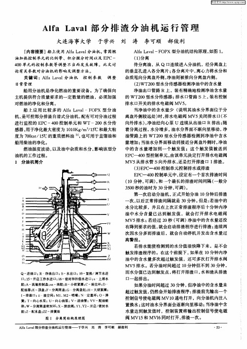
日常管理
Al a a— O X型分油机结构原理 , f Lvl F P a 如图 1 。
( ) 离 1分
待分离油 , Q 1连续进入分油机 ,经分离盘上 从 : 3
的垂直孔进入各分离片; 各分离片中 , 离心力将水分和
维普资讯
A a a 部 分 排 渣 分 油 机 运 行 管 理 la L v l f
大连 海事大学 于学兴 刘 涛 李可顺 郝俊 利
[ 内容提要 ] 船上使 用 A f L v 1 l aa 分油机 , a 常因燃 油加热控制单元的比例 带、积分微分时间以及 E C一 P 40 0 单元的控制参数等调整不 当而发 生故 障。此文讨
船用分油机是净化燃油的重要设备 。为了确保 向 主机提供符合质量要求 的一定数量 的燃油 ,必须加强
对燃油的净化和分离。 船 上应用 比较 多 的 A f L vl OP 型分油 l aa —F X a
机, 是可控部分排渣 自清式分油机 , 配有可对分油过程 进行监控 的 E C一4 0 P 0 控制单元 和 wT~20 0 水分传 感器 , 用于净化最大密度为 1 1K / 1℃和最大粘 00 g m /5
MV 从排水管 S向外排水 , 5 还是打开排渣 口 1 排渣。 ( ) P - 40 3E C 0 控制单元控制排水或排渣
E C 0 控制单元 中, P  ̄4 0 设定有一个首次排渣时间 (0 1 分钟 , 可调) 和一个最长的排渣时间间隔 ( , 一般分
30 秒的油时为 3 分钟 , 50 0 可凋) 。
超过触发值 , 仍然会开始排渣程序 : 排渣前先输 出一个 控制信号使电磁阀 MV1 通 电打开 ,向分油机 内注入 0
阿尔法拉瓦尔 P 灵活分离系统说明书
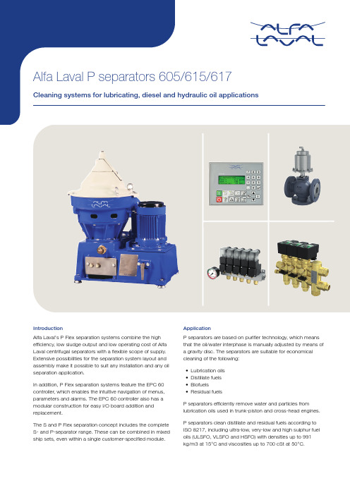
IntroductionAlfa Laval’s P Flex separation systems combine the high efficiency, low sludge output and low operating cost of Alfa Laval centrifugal separators with a flexible scope of supply. Extensive possibilities for the separation system layout and assembly make it possible to suit any installation and any oil separation application.In addition, P Flex separation systems feature the EPC 60 controller, which enables the intuitive navigation of menus, parameters and alarms. The EPC 60 controller also has a modular construction for easy I/O board addition and replacement.The S and P Flex separation concept includes the complete S- and P-separator range. These can be combined in mixed ship sets, even within a single customer-specified module.ApplicationP separators are based on purifier technology, which means that the oil/water interphase is manually adjusted by means of a gravity disc. The separators are suitable for economical cleaning of the following:•Lubrication oils•Distillate fuels•Biofuels•Residual fuelsP separators efficiently remove water and particles from lubrication oils used in trunk-piston and cross-head engines. P separators clean distillate and residual fuels according to ISO 8217, including ultra-low, very-low and high sulphur fuel oils (ULSFO, VLSFO and HSFO) with densities up to 991kg/m3 at 15°C and viscosities up to 700 cSt at 50°C.The P separator is optimized to clean biofuels according toEN15940 (HVO) and EN14214/ASTM D6751 (FAME).For treatment of other fuel types please consult your local Alfa Laval office.P separators are designed for automatic operation in periodically unmanned engine rooms at sea and in power stations ashore.Benefits•Small footprint, high flexibility — The small separator and the modular nature of the surrounding components allow easy installation and flexible positioning in the work shop.•No water tank or discharge pipe — No tank is needed to supply operating water, and no pipe is needed todischarge it. This further simplifies installation.•Separate feed pump — A separate feed pump reducespipework to and from the preheater.•High separation efficiency — An optimized design ensures the best possible separation efficiency from the bowl and disc stack.•Low oil loss — The separator’s highly efficientdisplacement ensures that virtually no oil is lost.•Effective discharge — Separated sludge and water areefficiently removed from the system.•Easy operation and service — The EPC 60 controller isdesigned for “one-button” starts and stops, as well asintuitive menu navigation. Information about parametersand alarms can be easily accessed, which simplifies both operation and troubleshooting. The EPC 60 also has aninterchangeable and flexible design that enables fastertroubleshooting and I/O board replacement.•Remote control and monitoring — Using either Ethernet or MODBUS communication, Flex systems and modulesbased on P separators 605/615/617 can be controlledand supervised remotely from the control room. A variety of alarm functions are available as standard. Extra I/Oboards can be added to the EPC 60 controller in order to enhance its monitoring capabilities.DesignSingle Flex module with separator (excluding heater and pump)The P Flex separation concept provides a wide range of alternatives for P separators. Depending on the need, a P separator can be supplied as a separator and ancillaries, as a customer-specified module, or as part of a comprehensive package including services and order specific documentation.Flex systemA P separator with ancillaries in the form of block components provides optimized use of space. This allows for local modularization or do-it-yourself assembly.Flex modulesA compact P separator module can be built to a customer-specified configuration from a wide range of modular skids and machine blocks. Multi-modules are possible, as well as mixed modules including one or several S separators and/or P separators for the simultaneous treatment of different types of mineral oils. All Flex modules are factory tested to ensure faster startup and commissioning.Scope of supplyA preventive maintenance programme based on service kits has been developed.•Maintenance intervals:–Intermediate Service every 2000 h or 3 months–Major Service every 8000 operating hours or 12months•Service spares kits contain all necessary spare parts for each service and maintenance checkpoint:–Intermediate Service Kit with O-rings and seals for separator bowl, inlet and outlet.–Major Service Kit with parts for drive system, belt,bearings and friction pads.•The System Manual includes detailed information in electronic or printed form:–Installation instructions –Operating instructions–Alarms and troubleshooting –Service and spare parts•Commissioning and technical services including start-ups,are available from all Alfa Laval offices.•All services can be incorporated into specially tailoredNonstop Performance packages. Details are available from local Alfa Laval offices.OptionsFeed pump options1.ALP feed pump with IE3 motor2.HEATPAC CBM heater3.HEATPAC EHM heater4.S&T Heat exchangerFlex separation systems based on P separators 605/615/617can be complemented with the following equipment:•Starter (always included in module version)•Feed pump •Strainer •Heater•Space heating•Temperature transmitter •Additional thermometers •Safety valve•Pressure transmitters •Steam shut-off valve kit •Sludge removal kit •Regulating valves •Needle valves•Air pressure reducer valve •Vibration switch•Flow regulating system •Sludge outlet valve kit•Emergency safety shutdown •Remote monitoring•Special cable glands, extended cables•Tailored pipe arrangement for multiple modules, including heater cross connectionWorking principle12457681.Untreated oil2.Clean oil3.Separated water4.Paring disc5.Gravity disc6.Disc stack7.Seal ring8.Discharge portThe P Flex separation systems based on P separators 605/615/617 are operated automatically by the EPC 60controller, except at startup of the separator. Untreated oil,heated to the correct temperature, is fed continuously to the separator. The separator is driven by an electric motor via a friction clutch and belt.The separator bowl is fixed at the top of a spindle, which is supported by bearings and special composite springs. This bowl can be arranged as a purifier or as a clarifier. Bothconfigurations remove sludge, which accumulates at the bowl periphery and is intermittently discharged.In a purifier configuration, both sludge and water are separated from the oil, which means that water iscontinuously discharged from the bowl. The EPC 60 controller automatically controls the admission of water for the water seal and the displacement of oil prior to sludge discharge, but a gravity disc is needed to establish the correct interphase position in the separator bowl, i.e. the boundary between the oil and the water seal. The size of the gravity disc must be matched to the oil’s density, viscosity/temperature and feed rate to the separator.In a clarifier configuration, a clarifier disc is fitted instead of a gravity disc. The water outlet is blocked, which means that the separator’s water-handling capacity is limited and that water accumulates like sludge.During normal operation, vital process parameters aremonitored. These parameters, as well as alarms, are indicated by easy-to-understand text messages on the LCD display of the EPC 60 controller.The EPC 60 controller provides many alarm functions,including alarms for low oil pressure, high sludge tank level (if the optional sludge removal kit is included) and power failure.Additional functions are available for a vibration alarm when the optional vibration switch is fitted.78910101112451.Untreated oil inlet2.Oil return3.Water inlet (C1 = Conditioning water, C2 = Opening water,C3 = Closing water)4.Clean oil outlet5.Sludge and water outlet6.Optional7.Feed pump8.Heater9.Pneumatically controlled change-over valve 10.Pressure transmitter 11.Control unit12.Regulating valve13.Solenoid valve block, water Technical dataMax. recommended capacity, l/h on lubricating oils for trunk piston enginesControl voltage 1–phase, 100/110/115/230 V Frequency 50 or 60 HzControl airMin 5 bar, max 8 bar Operating water pressureMin 2 bar, max 8 barDimensional drawingP 6051650 x 1200 x 110025610P 6151650 x 1200 x 110025610P 6171650 x 1200 x 1100256101 Including ALP feed pump, CBM heater and SRKThis document and its contents are subject to copyrights and other intellectual property rights owned by Alfa Laval AB (publ) or any of its affiliates (jointly “Alfa Laval”). No part of this document may be copied, re-produced or transmitted in any form or by any means, or for any purpose, without Alfa Laval’s prior express written permission. Information and services provided in this document are made as a benefit and service to the user, and no representations or warranties are made about the accuracy or suitability of this information and these services for any purpose. All rights are reserved.200006014-1-EN-GB© Alfa Laval How to contact Alfa LavalUp-to-date Alfa Laval contact details for all countries are always availableon our website at 。
alfa laval 605分油机说明书2

PA 605 Purifier SystemInstallation System ReferencePrinted Book No.Feb 2011577217-02 Rev. 8Published By:Alfa Laval Tumba ABSE-147 80 Tumba, SwedenTelephone: +46 8 530 650 00Telefax:+46 8 530 310 40© Alfa Laval Tumba AB Feb 2011This publication or any part there of may not be reproduced or transmitted by any process or means without prior written permission of Alfa Laval Tumba AB.Original instructionsContents577217-021 Technical Data (5)1.1Demand Specifications Water .......................................................................51.2Demand Specifications Air .............................................................................51.3System Data (6)2 Drawings (9)2.1Flow Chart ............................................................................................................92.2Drawings .............................................................................................................102.2.1P 605 Separator Mounting Drawing, DIN...............................................................102.2.2P 605 Separator with Sludge Removal Kit Mounting Drawing, DIN.......................112.2.3P 605 Separator Mounting Drawing, JIS................................................................122.2.4P 605 Separator with Sludge Removal Kit Mounting Drawing, JIS........................132.2.5P 605 Separator Basic Size Drawing .....................................................................142.2.6P 605 Separator Foundation Drawing....................................................................152.2.7Valve Block Water Dimension Drawing..................................................................162.2.8Control Unit EPC 50 Dimension Drawing...............................................................172.2.9Starter Dimension Drawing.....................................................................................182.3Electrical System Layout .............................................................................192.4Electrical Diagrams .........................................................................................202.4.1Cable List ..............................................................................................................202.4.2Interconnection Diagram, Starter ..........................................................................232.4.3Interconnection Diagram, Starter, cont. ................................................................242.4.4Interconnection Diagram, Transmitters .................................................................252.4.5Interconnection Diagram, Solenoid Valves ...........................................................262.4.6Interconnection Diagram, Solenoid Valves cont....................................................272.4.7Interconnection Diagram, Optional Equipment......................................................282.4.8Circuit Diagram, Power Circuits .............................................................................292.4.9Circuit Diagram, Separator Starter and Feed Pump .............................................302.4.10Circuit Diagram, ESD-relay and Trip Contacts (optional) (31)3 Remote Supervision ..........................................................................................334 Specifications . (35)4.1Cables ..................................................................................................................354.2Cable Routing ....................................................................................................364.3Oil, Water, Steam, and Condensate Piping ..............................................364.4Ambient Temperature Limitation ................................................................374.5Sludge Tank .......................................................................................................374.6Sludge Piping (39)5 Commissioning and Initial Start (41)5.1Completion Check List (41)5.2Initial Start-up ...................................................................................................435.2.1Calculating Operating Pressure.. (45)Storage (47)and6 Shut-down6.1Shut-down after Use (47)6.2Protection and Storage (48)6.3Reassembly and Start up (49)577217-02PA 605 PURIFIER SYSTEM INSTALLATION SYSTEM REFERENCE 1 TECHNICAL DATA 1Technical Data1.1 Demand Specifications Water1.2 Demand Specifications AirSpecific requirements regarding the qualityof air1Pressure 500 – 800 kPa (5 – 8 bar).2Free from oil, and solid particles larger than0.01 mm.3Dry, with dew point min. 10 °C below ambient temperature.N O T EElectrical interconnections must be made by qualified electricians.Mechanical interconnections must be made by qualified mechanical technicians.Poor quality of the operating water may with time cause erosion, corrosion and/or operating problems. The water shall be treated to meet certain demands.The following requirements are important:1Turbidity-free water, solids content <0,001% by volume.Max. particle size 50 µm.Deposits shall not be allowed to form in certain areas in the system.2Total hardness less than 180 mg CaCO3 per litre, which corresponds to 10 °dH or 12,5 °E. Hard water may with time form deposits in the operating mechanism. The precipitation rate isaccelerated with increased operating temperature and low discharge frequency. These effects become more severe the harder the water is.3Chloride content max. 100 ppm NaCl (equivalent to 60 mg Cl/l). Chloride ions contribute to corrosion on surfaces in contact with the operating water. Corrosion is a process that isaccelerated by increased separating temperature, low pH, and high chloride ion concentration. 46,5 < pH < 9Bicarbonate content (HCO3) min. 70mg HCO3 per litre, which corresponds to 3,2 °dKH.5Pressure 200 – 800 kPa (2 – 8 bar).N O T EAlfa Laval accepts no liability for consequencesarising from unsatisfactorily purified operatingwater supplied by the customer.577217-0251 TECHNICAL DATA PA 605 PURIFIER SYSTEM INSTALLATION SYSTEM REFERENCE6577217-021.3 System DataMediaFuel oil and lube oils for diesel engines Feed density, max.991 kg/m³ at 15 °CViscosity, max.50 cSt at 100 °C (600 cSt at 50 °C)Pressure:Oil inlet Oil outletSludge outlet from separator Max. 4 barMax. delivery height 2.5 bar open outlet Water outletopen outlet Feed temperature, max.100 °CAmbient temperature Min. +5 °C, max. +55 °C Operating water pressure Min 2 bar, max. 8 barOperating water temp.Min. +5 °C, max. +55 °C (unheated water)Operating water densityMax. 1000 kg/m³Operating water consumption (without make-up water) 3.8 litre/discharge Operating water flowto SV10: 8.0 l/m to SV 15: 18 l/m to SV 16: 0.9 l/mAir quality Instrument air Air pressure Min. 5 bar, max. 7 bar Discharge volume1.1 litre Separator drain connection size 3/4”Mains supply voltage3x400/440/480 V ± 10%Power consumption, control voltage; EPC supply voltage 230 V /110V/115 V/100V ± 10%, 10 A Control voltage, operating 24 V ACFrequency50 or 60 Hz ± max. 5%Ambient temperatureMax. 55 °C Control cabinet max. distance from unit 50 m Storage time before use (with bowl removed) 6 monthsStorage temp.Min. +0 °C, max. +70 °CStorage humidity Relative humidity (RH) 10% – 95 % Non Condensing Enclosure class Min. IP 54Service intervals:Note! Regularly check connections. Tighten if necessary.SeparatorInspection every 2000 hours or 3 months operation Overhaul every 8000 hours or 12 months operationPA 605 PURIFIER SYSTEM INSTALLATION SYSTEM REFERENCE 1 TECHNICAL DATASeparation System Planned Maintenance KitsHours Period Separator AncillaryEquipment100020004000 6 months Inspection1200018 months Overhaul24000 3 years OverhaulAs necessary Repair(components)With delivery InspectionT ools577217-0271 TECHNICAL DATA PA 605 PURIFIER SYSTEM INSTALLATION SYSTEM REFERENCE 8577217-02577217-0292Drawings2.1 Flow ChartX 023361D2.2 Drawings2.2.1 P 605 Separator Mounting Drawing, DINX 023853E2.2.2 P 605 Separator with Sludge Removal Kit Mounting Drawing, DINX 023856B2.2.3 P 605 Separator Mounting Drawing, JISX 023854E2.2.4 P 605 Separator with Sludge Removal Kit Mounting Drawing, JISX 023855B2.2.5 P 605 Separator Basic Size DrawingRef. 565297 Rev. 22.2.6 P 605 Separator Foundation DrawingX 023365A2.2.7 Valve Block Water Dimension DrawingRef. 1765927 Rev. 9X 0 2 3 3 6 7 A2.2.8 Control Unit EPC 50 Dimension DrawingRef. 5683042.2.9 Starter Dimension DrawingRef. 571340 Rev. 0X 0 2 3 3 7 0 A2.3 Electrical System L ayoutX 023857ARef. 576789 Rev. 12.4 Electrical Diagrams2.4.1 Cable L istRef. 571356 Rev. 1No.TypeConnection pointAInstructionConnection pointBRemarksPower cables (currents according to order)1MPRXCX 3x4Mains supply Starter Fuse 20 A 1MPRXCX 3x10Mains supply Starter Fuse 35 A 2MPRXCX 2x1.5Starter EPC 503MPRXCX 3x1.5Starter Separator motor 2.5 – 6.3 A 3MPRXCX 3x2.5Starter Separator motor 6.3 – 16 A71MPRXCX 2x1.5Starter Separator motor 4MPRXCX 3x1.5Starter Feed pump 0.4 – 6.3 A 4MPRXCX 3x2.5Starter Feed pump 6.3 – 10 A72MPRXCX2x1.5StarterFeed pumpNo.Type Connectionpoint A Instruction Connectionpoint BRemarksSignal cables11RFE-HF 1x2x0.75EPC 50SV114RFE-HF 1x2x0.75EPC 50SV1015RFE-HF 1x2x0.75EPC 50SV1516RFE-HF 1x2x0.75EPC 50SV1617RFE-HF 1x2x0.75EPC 50SSC PT118RFE-HF 1x2x0.75EPC 50SSC PT422RFE-HF 1 x2x0.75EPC 50SUM Alarm23RFE-HF 4x2x0.75EPC 50SSC TT1/TT250RFE-HF 4x2x0.75EPC 50Starter51RFE-HF 4x2x0.75EPC 50Starter52RFE-HF 1 x4x0.75EPC 50StarterOptions (as ordered)25(PVC 5GO.75)Starter SS, Sep.Switch Included inseparator switch 30RFE-HF 1 x4x0.75EPC 50YS, Vibr.Switch31RFE-HF 1 x4x0.75EPC 50SSC+EMC Rem. OP Unit32RFE-HF 1 x4x0.75EPC 50Rem. T emp. al.33MPRXCX 5x1.5EPC 50Rem. Start/stop34RFE-HF 1 x4x0.75EPC 50SSC+EMC Comm. Module35RFE-HF 1 x4x0.75Starter GS, Valve Switch36RFE-HF 1 x2x0.75EPC 50LS, Sludge Level37RFE-HF 1 x2x0.75EPC 50SV6, Sol. Valve For pneumaticsludge pump38MPRXCX 4x1.5EPC 50Syst.Emergency1)40RFE-HF 4x2x0.75EPC 50Power Unit45RFE-HF 1 x2x0.75Starter Power Unit41RFE-HF 1 x4x0.75EPC 50Steam Reg. Val44RFE-HF 1 x2x0.75EPC 50Shut-off Valve1)Cable cannot be longer than 25 meter to avoid voltage drop.Ref. 571356 Rev. 1Other equivalent and approved cables may be used.Cable areas are calculated with correction factor 0.7.Cables used are Shipboard Cables, designed according to IEC 92-3.Flame retardant according to IEC 332-3/A. Halogen-free according to IEC 754-1Code designations for cables obtainable through cable producers Helkama, Finland, and Acatel, France.Where SSC is indicated it should be a Signal Shielded Cable with the shield properly connected to earth as shown in the electrical drawings.For other connections, an armoured cable may be used provided the armour is connected to earth, as shown in the electrical drawings, and gives sufficient EMI protection. Copper wire armouring is normally used.2.4.2 Interconnection Diagram, StarterRef. 571072 Rev. 2 Sheet 12.4.3 Interconnection Diagram, Starter, cont.X 026650ARef. 571072 Rev. 2 Sheet 22.4.4 Interconnection Diagram, TransmittersX 026651ARef. 571072 Rev. 2 Sheet 32.4.5 Interconnection Diagram, Solenoid ValvesX 026652ARef. 57172 Rev. 2 Sheet 42.4.6 Interconnection Diagram, Solenoid Valves cont.2.4.7 Interconnection Diagram, Optional EquipmentX 023377A2.4.8 Circuit Diagram, Power CircuitsX 019248A2.4.9 Circuit Diagram, Separator Starter and Feed Pump2.4.10 Circuit Diagram, ESD-relay and Trip Contacts (optional)577217-023132577217-02PA 605 PURIFIER SYSTEM INSTALLATION SYSTEM REFERENCE 3 REMOTE SUPERVISION 3Remote SupervisionN O T EIt is possible to supervise the Purifier System froma remote position. It is, however, not possible tooperate the Purifier System from a remote position.Connection to steering system viaPROFIBUS or MODBUS fieldbus systems.PROFIBUS or MODBUS communicationprotocol can be used to connect an EPC 50Control Unit to a central steering system. TheEPC 50 Control Unit uses a PROFIBUS DP orMODBUS RTU. Every node, or EPC 50 ControlUnit, on the bus has a unique address, and canuse 200 bytes for data exchange. An interfaceboard is needed to connect an EPC 50 ControlUnit to the respective fieldbus system. This ismounted on the I/O card.Remote fieldbus connection for EPC 50 ControlUnit is for use in those cases where the userwants access to data and operation informationfrom the control cabinet, and supervision and/or remote control from his own steeringsystem.577217-02333 REMOTE SUPERVISION PA 605 PURIFIER SYSTEM INSTALLATION SYSTEM REFERENCE34577217-02AlternativePROFIBUSMODBUSUser interfaceT o be arranged by customer.T o be arranged by customer.CableCable for PROFIBUS aquired and installed by customer.Cable for MODBUS aquired and installed by customer.Manual Hardware and software instructions exist.Hardware and software instructions exist.BoardPart no. 31830-6559-1Part no. 31830-6558-1577217-0235PA 605 PURIFIER SYSTEM INSTALLATION SYSTEM REFERENCE 4 SPECIFICATIONS4Specifications4.1 CablesCable IdentificationAll cables are marked to simplify identification and fault finding.G 032224AG 032244AG 032214A G 032234A4 SPECIFICATIONS PA 605 PURIFIER SYSTEM INSTALLATION SYSTEM REFERENCE36577217-024.2 Cable Routing4.3 Oil, Water, Steam, and Condensate PipingFor piping to and from Alfa Laval equipment, see the specifications below .Specifications•The correct pipe size must be used in the oil system.•The number of bends in the oil pipes must be minimized.•The suction height must be as low as possible.•The oil feed pump must be a displacement type pump.•The pump must be positioned close to the oil tank.•The heater must be installed close to the purifier unit to maintain correct feed oil temperature.•The recirculation line should be connected either directly to the settling tank (HFO) or to the oil outlet line from the separator (LO).•The oil outlet line from the separator must be connected to the system tank for lube oil, or the service tank for fuel oil.S 002891A G 032273A577217-0237PA 605 PURIFIER SYSTEM INSTALLATION SYSTEM REFERENCE 4 SPECIFICATIONS4.4 Ambient Temperature Limitation4.5 Sludge TankSpecificationLeading classification societies state in their regulations for engine room equipment that the maximum ambient temperature permissible is +55 °C. To meet this regulation, it is essential that electrical and electronic components have good ventilation, ant temperature control.•Sludge tank volume per Purifier Systemshould cover approximately up to 2 days storage at a discharge interval of 2 hours (for discharge volumes see technical data).• A manhole should be installed for inspection and cleaning.•The tank should be fitted with a sounding pipe.•The tank floor, or most of it, should have a slope of minimum 15°.•The sludge outlet pump connection should be positioned in the lowest part of the tank.• A high level alarm switch, connected to the sludge pump, should be installed.•A heating coil should be used to keep the sludge warm and fluid while being pumped out.•Tank ventilation must follow the classification rules for evacuation of gases.•There should be a ventilation pipe to fresh air.•The ventilation pipe should be straight. If this is not possible, any bends must be gradual.•The ventilation pipe must not extend below the tank top.•A sludge tank with partition walls must have ventilation pipes in all compartments, orcutouts in the upper edge, to allow vapours to travel through the tank.G 004273ASludge outlet pump connectionMin. height 400 mmVentilation pipeSludge pipe connectionMin. slope 15°G 004274AManholeHigh level alarm switchHeating coil4 SPECIFICATIONS PA 605 PURIFIER SYSTEM INSTALLATION SYSTEM REFERENCE The number of ventilation pipes, and theirminimum dimension, depend on the size andnumber of separators connected to the sametank. See table below.Type 1 system 2 systemsP A 605 1 x ∅70 mm 1 x ∅100 mm38577217-02PA 605 PURIFIER SYSTEM INSTALLATION SYSTEM REFERENCE 4 SPECIFICATIONS 4.6 Sludge PipingG443A577217-02394 SPECIFICATIONS PA 605 PURIFIER SYSTEM INSTALLATION SYSTEM REFERENCE40577217-02G 004412APA 605 PURIFIER SYSTEMINSTALLATION SYSTEM REFERENCE5 COMMISSIONING AND INITIAL START5Commissioning and Initial Start5.1 Completion Check L istIt is essential before starting up the separation system that all units are in good operating condition and that all pipelines and control equipment are properly connected to assure correct operation.Use this check list as a guide for completing the system installation:W A R NI N G!Breakdown hazardCheck that the power frequency is in agreement with the machine plate. If incorrect, resulting overspeed may cause breakdown.1Check that transport seals are removed from all pipes.2Use flushing filters to prevent pipe work debris from being pumped into the separation system.N O T EThe flushing filters must be removed after initial flushing.3Check that all separators are in properworking condition. Follow the manufacturer’s instructions.4Make sure that separators are lubricated in accordance with instructions.5Separators are delivered without oil in the oil sump. For information on oil filling and oil type, see the Separator Manual booklet.G 08687T 15 COMMISSIONING AND INITIAL START PA 605 PURIFIER SYSTEM INSTALLATION SYSTEM REFERENCEN O T EToo much, or too little oil may result in damage to separator bearings.Neglecting an oil change may result in damage to separator bearings.6Power on.7Check that the separator rotation direction corresponds with the arrow on the frame by doing a quick start/stop (1–2 seconds.) and looking at the motor fan rotation.C A U T IO N!If power cables have been installed incorrectly, the separator will rotate in reverse, and vital rotating parts can unscrew.8Check the pump function and direction.PA 605 PURIFIER SYSTEM INSTALLATION SYSTEM REFERENCE 5 COMMISSIONING AND INITIAL START 5.2 Initial Start-upUse this check list for initial system start up:1Check that there is oil in the feed oil tank.2Check water and air supply. See ‘‘SystemData” on page 6.3Check power supplies to the control unit andthat the voltage is in accordance with data in‘‘System Data” on page 6.4Check all parameter settings in the controlunit. See Installation Parameters in theParameter List booklet.N O T EThe Control Unit is supplied with standardconfiguration parameters. You may have to makesome changes to suit your installation.5Start the separation system as described inthe Operating Instructions booklet.6Start up step by step, checking that themachine and units function properly.7Establish system pressures.The delivery height pressure is the pressure inthe oil pipe work down stream from theseparation system, due to the pipe bends andthe height (head) to the cleaned oil tank. If thecleaned oil tank is below the separationsystem the delivery height pressure may bevery low. The oil paring disc pressure will haveto be greater than the delivery height pressurefor any oil to flow.Proceed as follows:•Ensure the valves in the oil system are in thecorrect positions.•The oil should be at separation temperature.Cont.5 COMMISSIONING AND INITIAL START PA 605 PURIFIER SYSTEM INSTALLATION SYSTEM REFERENCE •Ensure that V5 is closed.•Fully open the back pressure regulating valveRV4.•The shut off valve V4 should be open.•Open SV15 for 3 seconds to prime theoperating slide.•Open SV16 for 15 seconds to close the bowl.•Open SV10 for 30 seconds to put water intothe bowl.•Feed oil to the separator at the normal flowrate by opening SV1.•Note the pressure in the oil outlet PT4, both onthe pressure gauge and in the EPC50 display.This pressure is P min.•Gradually close the back pressure regulatingvalve RV4. The pressure on PT4 will increase.The water pressure (PT5) decreases slightlyas the paring tube moves inwards. The waterpressure will suddenly drop when oil passesfrom the oil paring chamber to the waterparing chamber. Note the pressure of PT4both on the pressure gauge and in the EPC50display. This pressure is P max.•Open RV4.•Stop the oil feed to the separator and note thepressure in the oil outlet. This is the deliveryheight pressure P del.•Stop the heater.•Stop the separator.•Stop the feed pump when the heater hascooled.PA 605 PURIFIER SYSTEM INSTALLATION SYSTEM REFERENCE 5 COMMISSIONING AND INITIAL START5.2.1 Calculating Operating Pressure•Calculate the normal back pressure levelduring operation as follows:•Calculate the value for low pressure alarm setting (Pr 11) as follows:•Calculate the value for high pressure alarm setting (Pr 10) as follows:Adjust the back pressure to P normalSet Pr 11 to give alarm at pressure decreasing below the P low press. value.Set Pr 10 to give alarm at pressure increasing above the P high press. value.P min + P max= P normal2P min + P normal= P low press.2P normal + P max= P high press.25 COMMISSIONING AND INITIAL START PA 605 PURIFIER SYSTEM INSTALLATION SYSTEM REFERENCEPA 605 PURIFIER SYSTEMINSTALLATION SYSTEM REFERENCE6 SHUT-DOWN AND STORAGE6Shut-down and StorageStorage before InstallationIf the separation system is stored beforeinstallation, the following safeguards must be taken:6.1 Shut-down after UseIf the separation system is going to be shut down for a period of time, the following safeguards must be taken:Storage period < 6 months > 6 months SeeActionProtect from dust, dirt, water, etc.x x This chapter Protect with anti-rust oil x x This chapter Inspection xx Separator manual OverhaulxSeparator manualShut-down period < 3 months (stand-by)3 – 12 months > 12 monthsSeeActionRemove bowlx x xDismantling and Assembly in the Separator Manual Protect from dust, dirt, water, etc.x x x This chapter Protect with anti-rust oil xx x This chapter Inspection xx Separator manual OverhaulxSeparator manual6 SHUT-DOWN AND STORAGE PA 605 PURIFIER SYSTEM INSTALLATION SYSTEM REFERENCE 6.2 Protection and StorageAll system equipment, both the separator andthe ancillary equipment, must be stored indoorsat 5 – 55°C, if not delivered in water-resistantbox for outdoor storage.If there is a risk for condensation of water, theequipment must be protected by ventilation andheating above dew point.The following protection products arerecommended:•Anti-rust oil with long lasting effectivetreatment for external surfaces. The oil shouldprevent corrosion attacks and give a waxysurface.•Anti-rust oil (Dinitrol 40 or equivalent) thin andlubricating for inside protection. It gives alubricating transparent oil film.•Solvent, e.g. white spirit, to remove the anti-rust oil after the shut-down.•If the storage time exceeds 12 months, theequipment must be inspected every 6 monthsand, if necessary, the protection be renewed.Rubber Parts•Gaskets, O-rings and other rubber partsshould not be stored for more than two years.After this time, they should be replaced.SeparatorDismantle the separator bowl and take out theO-rings. Clean the bowl with oil and reassemblewithout the O-rings. Place in a plastic bag withsilica dessicant bags and seal the plastic bag.Grease the spindle.PA 605 PURIFIER SYSTEM INSTALLATION SYSTEM REFERENCE 6 SHUT-DOWN AND STORAGEValves, Pipes and Similar Equipment•Components like valves need to be cleanedwith solvent and treated with anti-rust oil (type112).•Water pipes should be drained and treatedwith anti-rust oil (type 112).•Articles made of rubber or plastics (e.g. seals)must not be treated with anti-rust oil.6.3 Reassembly andStart up•Clean away the anti-rust oil with white spirit.•Remove the silica gel bags from all units.•Follow all relevant instructions in the SeparatorManual and Operating Instructions.6 SHUT-DOWN AND STORAGE PA 605 PURIFIER SYSTEM INSTALLATION SYSTEM REFERENCE。
ALFA LAVAL_PA分油机操作说明(中文)
操作说明出版日期 2008年8月手册编号 1810896-02 V6Alfa Laval保留随时进行更改的权利,恕不另行通知。
对于本手册中可能存在的任何错误、遗漏,欢迎读者指正或提出改进建议,我们将不胜感激。
本手册复印件可从当地Alfa Laval公司购买。
出版公司:Alfa Laval Tumba ABSE - 147 80 TumbaSweden© Copyright Alfa Laval Tumba AB 2005目录1操作 (3)1.1启动前 (3)1.2操作员面板 (6)1.3启动 (7)1.4运行过程中 (10)1.5停机 (13)1.6紧急停机 (15)1.7紧急停机后 (15)1.8排渣间隔时间(仅适用于P625/635) (17)1.8.1 基本情况 (17)1.8.2 推荐排渣间隔时间 (17)1.8.3 燃油净化 (17)1.8.4 润滑油净化 (17)1.8.5 分离筒检查 (18)1810896-02PA 净化器系统操作说明2 1810896-02PA 净化器系统操作说明 1 操作1操作1.1启动前分油机中必须安装正确的比重环。
参见《分油机手册》中的“4.3.3 比重环选择”。
1. 检查分油机是否正确装配并连接正确电压和频率的电源。
损坏危险在启动之前应完成分油机的全面装配。
所有联轴器、挡盖和防护装置必须安装到位并紧固。
不符合规定可能导致设备损坏。
电气危险请遵照本地电气安装和接地规定操作。
损坏危险检查电源频率是否与机器铭牌一致。
如果不正确,由此造成的超速可能导致设备损坏。
1810896-02 3分油机只可用于Alfa Laval 公司规定限制范围内的用途。
否则可能导致严重损坏。
警告警告警告警告1 操作 PA 净化器系统操作说明2. 根据需要检查集油槽油位。
如不够需加到位。
4 1810896-02y 对于P 600、P 605、P 610和P 615: 油位应稍高于观察镜的中间位置。
- 1、下载文档前请自行甄别文档内容的完整性,平台不提供额外的编辑、内容补充、找答案等附加服务。
- 2、"仅部分预览"的文档,不可在线预览部分如存在完整性等问题,可反馈申请退款(可完整预览的文档不适用该条件!)。
- 3、如文档侵犯您的权益,请联系客服反馈,我们会尽快为您处理(人工客服工作时间:9:00-18:30)。
– accept/store a new parameter value.
The ‘+’ or the ‘–’ buttons are used to change the value flashing in the display window.
Process parameters
Any comments regarding possible errors and omissions or suggestions for improvement of this publication would be gratefully appreciated.
Copies of this publication can be ordered from your local Alfa Laval company.
Use the pressure gauge situated in the air valve block to check that the air supply is correct. See the Installation System Reference booklet.
1 OPERATING
PA Purifier System
Operating Instructions
Printed Book No.
Jun 2008 1810896-02 V 6
Alfa Laval reserves the right to make changes at any time without prior notice.
Sludge Discharges (Valid for P 625/635 only) ............17 1.8.1 Background ..........................................17 1.8.2 Recommended intervals between sludge discharges................................17 1.8.3 Fuel oil cleaning ...................................18 1.8.4 Lubricating oil cleaning ........................18 1.8.5 Bowl inspection ....................................20
! WARNING
Use the separation system for the purpose, and within the limits, specified by Alfa Laval. Failure to do so could cause a violent breakdown.
1810896-02
Published by:
Alfa Laval Tumba AB SE - 147 80 Tumba Sweden
© Copyright Alfa Laval Tumba AB 2008.
Contents
1 Operating...................................................3
Set the process parameters to suit the installation as follows:
1 Push ‘Enter’. Parameter no. 1 in the process
parameter list is displayed. You have now come to the process parameter list. Go through the list and set parameters.
X023719B
P003683A
1810896-02
5
1 OPERATING
1.2 Operator Panel
PA PURIFIER SYSTEM OPERATING INSTRUCTIONS
General principle
The ‘Enter’ button is used to:
– enter into a parameter list
ALARM
P004216B
6
1810896-02
G046602B
PA PURIFIER SYSTEM OPERATING INSTRUCTIONS
1.3 Startup
Before startup make sure that all the main supply valves for air, oil, and water are open. Open heating media supply valve if applicable. Switch on the power supplies. Make sure the control selection switch is in the manual position.
G0868543A
G08687K1
4
1810896-02
PA PURIFIER SYSTEM OPERATING INSTRUCTIONS
Rotation Direction
Check the rotation of the bowl by doing a quick start/stop. The motor fan must rotate in a clockwise direction.
OP
HEATER SEPARATION STOP DISCHARGE OP A CTIVE
ALARM
P004217B
P004218B
1810896-02
7
G046603B
P003992A
1 OPERATING
.
4 Start the separator.
PA PURIFIER SYSTEM OPERATING INSTRUCTIONS
2 When the parameters have been set, ‘End I/O’
(flashing) shows. Push ‘+’. ‘Standst.’ is now displayed.
TT PT
PT
16 15 10 EPC-50
INFO
Standst.
ENTER
OP
HEATER SEPARATION STOP DISCHARGE OP ACTIVE
5 Listen and observe.
Vibration may occur during start up, when passing critical speeds.This is normal and should pass without danger. If vibration increases, or continues at full speed, press the emergency stop button and stand clear until the vibration stops. The cause of vibration must be determined and corrected before starting again! See the Alarms and Fault Finding booklet.
! WARNING
Electrical hazard Follow local regulations for electrical installation and earthing (grounding).
! WARNING
Breakdown hazard Check that the power frequency is in agreement with the machine plate. If incorrect, resulting.
1 OPERATING
50 Hz? 60 Hz?
3
P003992A
X023714B
1 OPERATING
2 Check the oil sump level and top up if
necessary.
• For P 600, P 605, P 610, and P 615: The oil level should be slightly above middle of the sight glass.
1 Check that the separator is correctly
assembled and connected to power supply of correct voltage and frequency.
! WARNING
Breakdown hazard Assemble the separator completely before start. All couplings, covers, and guards must be in place and properly tightened. Non compliance may lead to breakdown.
1 Start the oil feed pump.
1 OPERATING
2 If necessary, vent air from the heater through
the relief valve (if applicable). Switch on the heater. (if applicable).
! CAUTION
If power cable polarity has been reversed, the separator will rotate in reverse, and vital rotating parts can loosen.