文献翻译—汽车车身焊装夹具的设计要点
浅谈白车身焊装夹具设计要点分析
浅谈白车身焊装夹具设计要点分析一、引言白车身焊装夹具设计是汽车生产中的关键环节之一,夹具设计的质量直接影响到整个生产线的效率和产品质量。
白车身焊装夹具设计的要点分析对于提高生产效率、降低生产成本、保证产品质量具有重要意义。
本文将从夹具设计的要点入手,分析影响夹具设计的关键因素,为相关从业人员提供参考。
二、白车身焊装夹具设计的要点分析1. 结构设计白车身焊装夹具的结构设计是决定其功能和稳定性的关键。
优秀的结构设计应该具有简单、坚固、稳定的特点。
夹具应该能够固定车身零部件,确保其在焊接过程中不会发生位移或变形。
夹具的结构应该简单,易于安装和拆卸,便于操作人员进行维护和保养。
夹具的结构应该坚固耐用,能够承受汽车生产线高频率的使用,确保生产过程的稳定性和安全性。
2. 材料选择夹具设计中的材料选择直接关系到夹具的耐用性和使用寿命。
应该选择具有良好的机械性能和抗腐蚀性能的材料,以确保夹具在高频使用的情况下不易损坏和生锈。
对于一些特殊工艺需求的夹具设计,应根据具体情况选择合适的特种材料,以保证夹具的稳定性和可靠性。
3. 工艺要求夹具设计应该考虑到生产工艺的需求,确保夹具能够适应不同产品的焊接要求。
对于多品种、小批量生产的汽车生产线,夹具设计需要具有一定的灵活性,能够适应不同车型的生产需求。
夹具的设计也应考虑到组装和拆卸的便捷性,以减少生产线上的换线时间,提高生产效率。
4. 精度控制夹具设计中的精度控制是保证产品质量的关键。
夹具应该具有良好的定位和固定能力,确保焊接工艺中的高精度要求得以满足。
对于一些需要提高精度的工序,如车身焊接中的角度、尺寸等要求,夹具的设计应该考虑到这些因素,保证产品焊接后的精度和稳定性。
5. 成本控制夹具设计中的成本控制是企业经营的重要因素。
夹具的设计应该充分考虑生产成本、工时成本等因素,选择合适的设计方案来降低生产成本。
夹具的使用寿命也是成本控制的重要因素,应尽量选择耐用、易维护的设计方案,以减少后期的维护和更换成本。
汽车车身焊装夹具设计
汽车车身焊装夹具设计汽车焊接生产线是汽车制造中的关键,焊接生产线中的各种工装夹具又是焊装线的重中之重,焊接夹具的设计则是前提和基础。
设计工装夹具时,不仅要考虑生产纲领,还必须要熟悉产品结构,了解钣金件变形特点,通晓工艺要求等诸多内容。
汽车制造四大工艺中,焊装尤其重要,而在焊装的前期规划中,车身焊接夹具的设计又是关键环节。
工装夹具的设计是一门经验性很强的综合性技术,在设计时首先应考虑的是生产纲领,同时还必须熟悉产品结构,了解钣金件变形特点,把握零部件装配精度及容差分配,通晓工艺要求。
只有做到这些,才能对焊接夹具进行全方位的设计,满足生产制造要求。
下面就汽车车身焊装夹具设计做一些探讨。
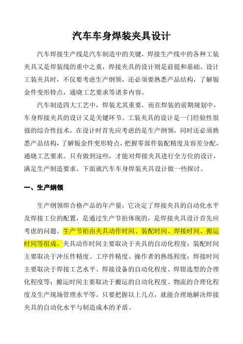
一、生产纲领生产纲领即合格产品的年产量,它决定了焊接夹具的自动化水平及焊接工位的配置,是通过生产节拍体现的,是焊接夹具设计首先应考虑的问题。
生产节拍由夹具动作时间、装配时间、焊接时间、搬运时间等组成。
夹具动作时间主要取决于夹具的自动化程度;装配时间主要取决于冲压件精度、工序件精度、操作者的熟练程度;焊接时间主要取决于焊接工艺水平、焊接设备的自动化程度、焊钳选型的合理化程度等;搬运时间主要取决于搬运的自动化程度、物流的合理化程度及生产现场管理水平等。
只要把握以上几点,就能合理地解决焊接夹具的自动化水平与制造成本的矛盾。
二、汽车车身的结构特点汽车车身一般由外覆盖件、内覆盖件和骨架件组成,覆盖件的钢板厚度一般为0.8~1.2mm,有的车型外覆盖件钣金厚度仅有0.6mm、0.7mm,骨架件的钢板厚度多为1.2~2.5mm,也就是说它们大都为薄板件。
对焊接夹具设计来说,应考虑如下特点:1、刚性差、易变形经过成型的薄板冲压件有一定的刚性,但与机械加工件相比,刚性要差得多,而且单个大型冲压件容易变形,只有焊接成车身壳体后,才具有较强的刚性。
以轿车车身大侧围外板为例,一般材料厚度为0.7~0.8mm,绝大多数是0.8mm,拉延形成空腔后,刚性非常差,当和内板件焊接形成侧围焊接总成后才具有较强的刚性。
汽车焊接夹具设计外文文献翻译
汽车焊接夹具设计外文文献翻译(含:英文原文及中文译文)文献出处:Semjon Kim.Design of Automotive Welding Fixtures [J]. Computer-Aided Design, 2013, 3(12):21-32.英文原文Design of Automotive Welding FixturesSemjon Kim1 AbstractAccording to the design theory of car body welding fixture, the welding fixture and welding bus of each station are planned and designed. Then the fixture is modeled and assembled. The number and model of the fixture are determined and the accessibility is judged. Designed to meet the requirements of the welding fixture.Keywords: welded parts; foundation; clamping; position1 IntroductionAssembly and welding fixtures are closely related to the production of high-quality automotive equipment in automotive body assembly and welding lines. Welded fixtures are an important part of the welding process. Assembly and welding fixtures are not only the way to complete the assembly of parts in this process, but also as a test and calibration procedure on the production line to complete the task of testing welding accessories and welding quality. Therefore, the design and manufacture ofwelding fixtures directly affect the production capacity and product quality of the automobile in the welding process. Automotive welding fixtures are an important means of ensuring their manufacturing quality and shortening their manufacturing cycle. Therefore, it is indispensable to correctly understand the key points of welding fixture design, improve and increase the design means and design level of welding fixtures, and improve the adjustment and verification level of fixtures. It is also an auto manufacturing company in the fierce competition. The problem that must be solved to survive.The style of the car is different from that of the car. Therefore, the shape of the welding jig is very different. However, the design, manufacture, and adjustment are common and can be used for reference.2. Structural design of welding fixtureThe structure design of the welding fixture ensures that the clip has good operational convenience and reliable positioning of the fixture. Manufacturers of welding fixtures can also easily integrate adjustments to ensure that the surfaces of the various parts of the structure should allow enough room for adjustments to ensure three-dimensional adjustment. Of course, under the premise of ensuring the accuracy of the welding jig, the structure of the welding jig should be as simple as possible. The fixture design is usually the position of all components on the fixture is determined directly based on the design basis, and ultimately ensure thatthe qualified welding fixture structure is manufactured. According to the working height, the height of the fixture bottom plate can be preliminarily determined, that is, the height of the fixture fixing position. The welding fixture design must first consider the clamping method. There are two types, manual and pneumatic. Manual clamping is generally suitable for small parts, external parts, and small batches of workpieces. For large body parts, planning in the production line, automation High-demand welding fixtures should be pneumatically clamped. Automobile production is generally pneumatically clamped, and manual mass clamping can be used as auxiliary clamping. This can reduce costs accordingly. Some manual clamping products already have standard models and quantities, which can be purchased in the market when needed. For some devices, pneumatic clamping is specified, but if pneumatic clamping is used, the workpiece may be damaged. Therefore, it is possible to manually press the place first to provide a pneumatic clamping force to clamp the workpiece. This is manual-pneumatic. . The fixture clamping system is mounted on a large platform, all of which are fixed in this welding position to ensure that the welding conditions should meet the design dimensions of the workpiece coordinate system positioning fixture, which involves the benchmark.3. Benchmarks of assembly and welding fixtures and their chosen support surfaces3.1 Determination of design basisIn order to ensure that the three-dimensional coordinates of the automatic weldment system are consistent, all welding fixtures must have a common reference in the system. The benchmark is the fixture mounting platform. This is the X, Y coordinate, each specific component is fixed at the corresponding position on the platform, and has a corresponding height. Therefore, the Z coordinate should be coordinated, and a three-dimensional XYZ coordinate system is established. In order to facilitate the installation and measurement of the fixture, the mounting platform must have coordinates for reference. There are usually three types. The structure is as follows:3.1.1 Reference hole methodThere are four reference holes in the design of the installation platform, in which the two directions of the center coordinates of each hole and the coordinates of the four holes constitute two mutually perpendicular lines. This is the collection on the XY plane coordinate system. The establishment of this benchmark is relatively simple and easy to process, but the measurements and benchmarks used at the same time are accurate. Any shape is composed of spatial points. All geometric measurements can be attributed to measurements of spatial points. Accurate spatial coordinate acquisition is therefore the basis for assessing any geometric shape. Reference A coordinated direction formed by oneside near two datums.3.1.2 v-type detection methodIn this method, the mounting platform is divided into two 90-degree ranges. The lines of the two axes make up a plane-mounted platform. The plane is perpendicular to the platform. The surface forms of these two axis grooves XY plane coordinate system.3.1.3 Reference block methodReference Using the side block perpendicular to the 3D XYZ coordinate system, the base of a gage and 3 to 4 blocks can be mounted directly on the platform, or a bearing fixing fixture platform can be added, but the height of the reference plane must be used to control the height , must ensure the same direction. When manufacturing, it is more difficult to adjust the previous two methods of the block, but this kind of measurement is extremely convenient, especially using the CMM measurement. This method requires a relatively low surface mount platform for the reference block, so a larger sized mounting platform should use this method.Each fixture must have a fixed coordinate system. In this coordinate system, its supporting base coordinate dimensions should support the workpiece and the coordinates correspond to the same size. So the choice of bearing surface in the whole welding fixture system 3.2When the bearing surface is selected, the angle between the tangentplane and the mounting platform on the fixed surface of the welding test piece shall not be greater than 15 degrees. The inspection surface should be the same as the welded pipe fittings as much as possible for the convenience of flat surface treatment and adjustment. The surface structure of the bearing should be designed so that the module can be easily handled, and this number can be used for the numerical control of the bearing surface of the product. Of course, designing the vehicle body coordinate point is not necessarily suitable for the bearing surface, especially the NC fixture. This requires the support of the fixture to block the access point S, based on which the digital surface is established. This surface should be consistent with the supported surface. So at this time, it is easier and easier to manufacture the base point S, CNC machining, precision machining and assembly and debugging.3.2 Basic requirements for welding fixtureIn the process of automobile assembly and production, there are certain requirements for the fixture. First, according to the design of the automobile and the requirements of the welding process, the shape, size and precision of the fixture have reached the design requirements and technical requirements. This is a link that can not be ignored, and the first consideration in the design of welding fixture is considered. When assembling, the parts or parts of the assembly should be consistent with the position of the design drawings of the car and tighten with the fixture.At the same time, the position should be adjusted to ensure that the position of the assembly parts is clamped accurately so as to avoid the deformation or movement of the parts during the welding. Therefore, this puts forward higher requirements for welding jig. In order to ensure the smooth process of automobile welding and improve the production efficiency and economic benefit, the workers operate conveniently, reduce the strength of the welder's work, ensure the precision of the automobile assembly and improve the quality of the automobile production. Therefore, when the fixture design is designed, the design structure should be relatively simple, it has good operability, it is relatively easy to make and maintain, and the replacement of fixture parts is more convenient when the fixture parts are damaged, and the cost is relatively economical and reasonable. But the welding fixture must meet the construction technology requirements. When the fixture is welded, the structure of the fixture should be open so that the welding equipment is easy to close to the working position, which reduces the labor intensity of the workers and improves the production efficiency.4. Position the workpieceThe general position of the workpiece surface features is determined relative to the hole or the apparent positioning reference surface. It is commonly used as a locating pin assembly. It is divided into two parts: clamping positioning and fixed positioning. Taking into account thewelding position and all welding equipment, it is not possible to influence the removal of the final weld, but also to allow the welding clamp or torch to reach the welding position. For truly influential positioning pins and the like, consider using movable positioning pins. In order to facilitate the entry and exit of parts, telescopic positioning pins are available. The specific structure can be found in the manual. The installation of welding fixtures should be convenient for construction, and there should be enough space for assembly and welding. It must not affect the welding operation and the welder's observation, and it does not hinder the loading and unloading of the weldment. All positioning elements and clamping mechanisms should be kept at a proper distance from the solder joints or be placed under or on the surface of the weldment. The actuator of the clamping mechanism should be able to flex or index. According to the formation principle, the workpiece is clamped and positioned. Then open the fixture to remove the workpiece. Make sure the fixture does not interfere with opening and closing. In order to reduce the auxiliary time for loading and unloading workpieces, the clamping device should use high-efficiency and quick devices and multi-point linkage mechanisms. For thin-plate stampings, the point of application of the clamping force should act on the bearing surface. Only parts that are very rigid can be allowed to act in the plane formed by several bearing points so that the clamping force does not bend the workpiece or deviate from thepositioning reference. In addition, it must be designed so that it does not pinch the hand when the clamping mechanism is clamped to open.5. Work station mobilization of welding partsMost automotive solder fittings are soldered to complete in several processes. Therefore, it needs a transmission device. Usually the workpiece should avoid the interference of the welding fixture before transmission. The first step is to lift the workpiece. This requires the use of an elevator, a crane, a rack and pinion, etc. The racks and gears at this time Structure, their structural processing, connection is not as simple as the completion of the structure of the transmission between the usual connection structure of the station, there are several forms, such as gears, rack drive mechanism, transmission mechanism, rocker mechanism, due to the reciprocating motion, shake The transfer of the arm mechanism to the commissioning is better than the other one, so the common rocker arm transfer mechanism is generally used.6 ConclusionIn recent years, how to correctly and reasonably set the auxiliary positioning support for automotive welding fixtures is an extremely complicated system problem. Although we have accumulated some experience in this area, there is still much to be learned in this field. Learn and research to provide new theoretical support for continuous development and innovation in the field of welding fixture design. Withthe development of the Chinese automotive industry, more and more welding fixtures are needed. Although the principle of the fixture is very simple, the real design and manufacture of a high-quality welding fixture system is an extremely complicated project.中文译文汽车焊接夹具的设计Semjon Kim1摘要依据车体焊装线夹具设计理论, 对各工位焊接夹具及其焊装总线进行规划、设计, 之后进行夹具建模、装配, 插入焊钳确定其数量、型号及判断其可达性,最终设计出符合要求的焊接夹具。
汽车车身焊装夹具设计概述
汽车车身焊装夹具设计概述汽车车身焊装夹具是一种用于固定和支撑车身零件的工具,它可以提供精确的定位和支撑车身零件的功能,使得工人能够在车身组装过程中更加高效和准确。
本文将对汽车车身焊装夹具设计进行概述,包括其定义、应用、设计要素等内容。
汽车车身焊装夹具可以被广泛应用于各类汽车焊装过程中,如钣金加工、车身冲压、车身清洗等。
在各类焊接过程中,夹具被用于固定工件,以确保焊接的位置和位置准确。
除此之外,夹具还可以用于提供支撑和保护,以避免工件变形或者受到损坏。
1. 夹具构造设计要素汽车车身焊装夹具的构造设计要素包括夹具体、夹具底座、夹具架等。
夹具体一般采用可调式结构,以保证夹紧力的准确性和夹紧力的均匀分布。
夹具底座一般采用铸铁或钢铁制造,以保证夹具的稳定性和刚度。
夹具架一般采用焊接结构,以提供车身零件的支撑和定位。
汽车车身焊装夹具的夹紧方式一般有机械式和液压式两种。
机械式夹紧方式通常采用螺旋式结构,夹紧力度可以根据需求进行调节,但是夹紧效果依赖于螺旋的精度和力度控制。
液压式夹紧方式通常采用液压缸,夹紧力度可以根据需求进行调节,但是液压管路和液压缸的输入需要考虑更多的因素,如泄漏、故障等。
3. 其他设计要素汽车车身焊装夹具的其他设计要素包括加工精度、尺寸准确性和表面光泽度等。
这些要素可以影响夹具的质量和功能,需要在设计阶段对其进行适当的考虑和调整。
另外,夹具的防护和维护也是需要重视的,以保证夹具的使用寿命和效率。
四、总结汽车车身焊装夹具是一种关键的工具,它对汽车生产的质量和效率有着重要的影响。
在设计汽车车身焊装夹具时,需要考虑多种因素,如夹具构造、夹紧方式、加工精度等。
通过合理的设计和制造,可以提升焊接的准确性和效率,为汽车生产提供良好的保障。
浅谈白车身焊装夹具设计要点分析

浅谈白车身焊装夹具设计要点分析白车身是未油漆的未喷涂的车身结构,焊装夹具是将车身构件精确定位并固定在正确的位置以执行焊接及装配工作的工具。
白车身焊装夹具在制造汽车过程中起到至关重要的作用,因为所有的焊接和装配工作都需要夹具的精确定位和固定。
设计一个高质量的白车身焊装夹具需要考虑以下几个要点:1.准确性白车身焊装夹具的设计必须保证其位置准确性。
设计师必须十分注重夹具定位的精确度并要避免夹具设计上的缺陷。
夹具应能够确保车身构件在焊接和装配过程中的精确位置,使整个车身部件在排除公差的情况下,按照汽车生产要求进行装配。
夹具设计务必要保证构件的精度控制固定度的控制,使焊接后的车身质量达到最优。
2.可持续性可持续性是夹具的关键要素之一。
长期保持夹具的高品质和生产效率是一个主要目标。
夹具应具有耐腐蚀性,耐用性及长期的可靠性。
夹具设计师应考虑材料的选择以保证夹具的可持续性,例如不锈钢和高强度钢材料。
另外,夹具应设计成易于维护及更换零件,这样才能为企业带来更好的生产效益。
3.灵活性和可拆卸性夹具必须具有灵活性和可拆卸性,这意味着夹具应能够适应不同的车型、不同的焊接和装配位置,同时可以轻松地拆卸和更换。
灵活性和可拆卸性可以极大地提高夹具的生产效率和有效性。
更为重要的是,这种设计方式还可以缩短焊接和安装时间,从而增加汽车生产线的生产能力。
4.可靠性白车身焊装夹具是汽车制造中必不可少的工具,设计师必须确保夹具具有高可靠性。
夹具应具有足够的强度和稳定性,可以承受长期的使用。
夹具应该经过充分的实验验证和检测,以确保其在使用过程中不会出现任何问题。
在这方面,使用有效的质量检测设施能够确保夹具在任何条件下都能够保持安全和稳定。
5.安全性安全是白车身焊装夹具最重要的考虑因素之一。
夹具的安全性与工人的安全息息相关。
对于焊装夹具的设计,必须考虑到夹具的结构、使用过程中的安全措施、以及对工人的影响。
夹具设计应该将人因素考虑在内,尽可能减少可能的工伤和疲劳。
汽车车身焊装夹具设计概述

汽车车身焊装夹具设计概述汽车车身焊装夹具是汽车制造中不可或缺的工具之一。
它在汽车的生产过程中起到了重要的作用,能够确保汽车车身的质量和稳定性。
本文将对汽车车身焊装夹具的设计进行概述,包括其定义、分类、设计原则和注意事项。
一、汽车车身焊装夹具的定义汽车车身焊装夹具是用于夹持汽车车身零部件的工具,它能够将零部件固定在正确的位置上,以便进行焊接和装配操作。
它由夹持机构、定位机构和支撑机构等部分组成,能够确保汽车车身的精确定位和稳定固定。
二、汽车车身焊装夹具的分类1.按照夹持方式分类:夹紧式夹具和真空吸盘式夹具。
夹紧式夹具通过夹紧零部件来固定,适用于结构坚固的零部件;真空吸盘式夹具通过负压将零部件吸附在夹具表面,适用于表面光滑的零部件。
2.按照应用领域分类:车身固定夹具和装配夹具。
车身固定夹具用于固定整个车身,在焊接过程中保持车身的稳定;装配夹具用于夹持和定位车身的零部件,保证零部件的正确装配位置和质量。
三、汽车车身焊装夹具的设计原则1.精确定位:夹具需要能够对零部件进行准确的定位,以保证焊接和装配的精确度。
2.稳定夹持:夹具需要能够稳定地夹持零部件,防止其在焊接过程中发生位移和震动。
3.易于操作:夹具的设计应尽量简单,方便操作人员使用,提高工作效率。
4.刚性要求:夹具需要具有足够的刚性,能够承受焊接过程中的应力和力量,确保零部件的稳定性和焊接质量。
5.安全性要求:夹具应符合安全规范,减少操作过程中的安全隐患,保障操作人员的安全。
四、汽车车身焊装夹具的设计注意事项1.夹具结构要合理:夹具的结构设计应根据零部件的形状和特性进行合理的布局,保证夹具能够夹持零部件的关键点,同时尽量减少夹具的重量。
2.夹具表面要光滑:夹具表面的光滑程度会影响真空吸盘式夹具的吸附效果,因此需要保证夹具表面的光滑度和质量。
4.考虑可拓展性:夹具的设计应该具有可拓展性,能够适应不同型号和规格的汽车车身零部件的夹持和装配需求。
汽车车身焊装夹具设计是汽车制造中不可或缺的一部分。
汽车车身焊装夹具设计概述
汽车车身焊装夹具设计概述一、汽车车身焊装夹具的概念汽车车身焊装夹具是用于固定汽车车身焊接部件的一种专用工装设备,它能够确保焊接部件的正确位置和角度,保证焊接的质量和精度。
它主要包括夹具主体、夹具夹具和定位元件等部件,可以根据焊接部位的不同,设计相应的夹具结构和功能。
二、汽车车身焊装夹具设计的原则1. 精准度和稳定性:夹具设计必须保证焊接部件的精准度和稳定性,确保焊接的质量和一致性。
2. 生产效率和灵活性:夹具设计要考虑生产效率和灵活性,以适应不断变化的焊接需求和车型种类。
3. 成本控制和可维护性:夹具设计要尽可能控制成本,降低制造和维护成本,并考虑夹具的可维护性和寿命问题。
三、汽车车身焊装夹具的主要类型1. 手工夹具:手工夹具是最基础的夹具类型,主要用于小批量生产和定制车型,需要人工操作和调整。
2. 气动夹具:气动夹具利用气动装置实现夹紧和释放的功能,适用于中小型车身焊装生产线。
3. 液压夹具:液压夹具采用液压系统实现夹紧和释放的功能,适用于大型车身焊装生产线。
4. 智能夹具:智能夹具结合了传感器、控制系统和机电一体化技术,能够实现自动调整和自适应功能,适用于高效率、高精度的大规模生产。
四、汽车车身焊装夹具设计流程1. 确定夹具类型:根据焊接部位和生产需求,确定适合的夹具类型,包括手工夹具、气动夹具、液压夹具和智能夹具。
2. 确定夹具结构:根据焊接部位的形状和特点,设计夹具结构和功能,包括夹具主体、夹具夹具、定位元件等部件。
3. 材料选型和制造:选择适合的材料和制造工艺,既要考虑夹具的强度和刚度,又要兼顾制造成本和周期。
4. 装配调试和调整:对设计好的夹具进行装配和调试,确保夹具的稳定性和精确度,以便进行后续的生产。
5. 生产应用和维护保养:将设计好的夹具投入生产应用,不断进行维护保养和改进优化,持续提高生产效率和质量。
五、结语汽车车身焊装夹具设计是汽车焊装工艺中非常重要的一环,它直接影响着汽车焊接质量和生产效率。
汽车焊接夹具设计中英文对照外文翻译文献
汽车焊接夹具设计中英文对照外文翻译文献(文档含英文原文和中文翻译)汽车焊接夹具的设计1摘要依据车体焊装线夹具设计理论,对各工位焊接夹具及其焊装总线进行规划、设计,之后进行夹具建模、装配,插入焊钳确定其数量、型号及判断其可达性,最终设计出符合要求的焊接夹具。
关键词:焊接部件;基础;夹紧;位置1.介绍装配和焊接夹具在汽车车身装配和焊接生产线与生产制造优质的汽车设备息息相关。
焊装夹具,是焊接工艺的重要组成部分。
装配和焊接夹具除了是完成这个过程中零部件装配的途径和定位,同时在生产线上也作为一个测试和校准程序,完成检测焊接配件和焊接质量的任务。
因此焊装夹具的设计和制造,直接影响焊接过程中汽车的生产能力和产品质量。
汽车焊装夹具是保证其制造质量、缩短其制造周期的重要手段。
因此,正确理解焊装夹具设计要点,改善和提高焊装夹具的设计手段和设计水平,并提高夹具的调整和验证水平等三方面都是必不可少的,也是汽车制造公司在激烈的竞争中得以生存所必须解决的问题。
汽车的风格不同,焊接夹具的形状,因而有着很大的不同,但在设计、制造和调整都是共同的,可以借鉴采用。
2.焊接夹具的结构设计焊接夹具的结构设计,确保该夹具有良好的操作方便性、装夹定位的可靠性。
焊装夹具的制造商也很容易集成的调整,以保证结构各部分的表面应该允许足够的空间用于调整,以确保立体可调。
当然,在确保焊接夹具质量准确性的前提下,焊接夹具的结构应尽可能简单。
夹具设计通常是夹具上全部元件的位置都是直接根据设计基准确定的,最终保证制造出合格的焊接工装结构。
根据作业高度可初步决定夹具底板的高度,即夹具固定位置的高度。
焊接夹具设计首先要考虑夹紧方式,一般有手动和气动两种,手动夹紧一般适合于小件、外协件、小批量工件焊装,对于大型车体部件、规划于生产线内、自动化程度要求高的焊接夹具宜选用气动夹紧,汽车生产的一般采用气动夹紧,然后手工大批量夹紧可作为辅助夹紧。
这样可以相应的降低成本。
汽车车身焊装夹具设计概述

汽车车身焊装夹具设计概述车身焊装夹具设计是汽车生产线上非常重要的一环,它们用于固定和连接车身部件,确保生产过程中的准确性和稳定性。
本文将对汽车车身焊装夹具设计进行概述,包括设计要求、设计过程、常用设计软件以及设计流程等方面进行详细介绍。
一、设计要求车身焊装夹具设计的主要要求包括以下几个方面:1.准确性:夹具应具有很高的准确性,能够确保焊装过程中不发生偏差和错位。
2.稳定性:夹具应能够稳定地固定车身部件,以进行焊接等操作。
3.可操作性:夹具应易于操作,并且能够适应不同车身部件的夹持。
4.可靠性:夹具的设计应具有足够的强度和刚度,以确保工作时不产生变形或破坏。
5.安全性:夹具应符合相关安全标准,并且在使用过程中不会对人员造成伤害。
二、设计过程车身焊装夹具设计的一般流程如下:1.需求分析:根据生产线的需求和具体车型的要求,确定夹具的功能和使用条件。
2.方案设计:根据需求分析的结果,制定初步夹具设计方案。
包括夹具的整体结构、夹持方式、工作面积、夹持力等。
3.详细设计:在方案设计的基础上,进一步进行详细设计。
包括夹具各个部件的尺寸、材料选择、连接方式等。
4.制造与装配:按照设计要求制造夹具各个部件,并进行装配和调试。
5.试用与调整:在实际生产线上试用夹具,并根据使用情况进行调整和改进。
6.验收与使用:夹具通过验收后,正式投入使用。
三、常用设计软件进行车身焊装夹具设计时,常用的设计软件包括:1.Catia:该软件是一种三维设计软件,具有强大的建模和分析功能,适合进行夹具的结构设计和分析。
2.Autodesk AutoCAD:这是一种二维绘图软件,适合进行夹具的细节设计和图纸制作。
3.Solidworks:该软件具有强大的三维建模和装配功能,适合进行夹具的三维设计和装配模拟。
总结:车身焊装夹具设计是汽车生产线上不可或缺的一部分,它们的设计旨在确保车身部件在焊装过程中的准确性和稳定性。
设计夹具需要考虑准确性、稳定性、可操作性、可靠性和安全性等要求,并遵循一定的设计流程。
浅谈白车身焊装夹具设计要点分析
浅谈白车身焊装夹具设计要点分析
白车身焊装夹具是汽车生产中常用的工装设备,主要用于固定和定位车身零部件,使
其在焊接过程中达到精确的配合度和位置。
其设计质量直接影响到焊接质量和生产效率。
下面将从几个要点分析白车身焊装夹具的设计。
一、夹具的功能需求
白车身焊装夹具的主要功能是固定和定位车身零部件。
在设计夹具时,要充分考虑零
部件的形状、尺寸、重量等因素,确保夹具能够稳定可靠地固定零部件,并准确定位。
同
时还需要考虑夹具的多样性和可调性,以适应不同型号的车辆生产需求。
二、夹具的刚度和稳定性
夹具的刚度和稳定性对于保证焊接质量至关重要。
夹具在使用过程中要能够承受所需
的夹持力和挠度,不产生变形或松动,以确保零部件的精确位置和配合度。
在夹具设计中,需要采用合适的材料和结构,同时考虑到夹具的重量和刚度之间的平衡。
三、夹具的操作性和安全性
夹具的设计应便于操作和调整,能够方便、快捷地进行零部件的固定和定位。
在夹具
的安全性方面,要考虑到操作人员的安全和舒适性,尽可能减少夹具操作对人的伤害和疲劳。
夹具本身也要具备良好的稳定性和抗倾覆性,确保夹具在使用过程中不会发生意外事故。
白车身焊装夹具的设计要点分析包括功能需求、刚度和稳定性、操作性和安全性、可
靠性和维修性等多个方面。
在设计过程中,需要充分考虑到零部件的特性和生产的要求,
以提高夹具的适应性和实用性。
通过合理的设计和制造,能够提高车辆生产的效率和质量,降低生产成本,促进企业的发展。
浅谈白车身焊装夹具设计要点分析

浅谈白车身焊装夹具设计要点分析白车身焊装夹具是指用于汽车生产中,把未涂漆的车身零部件按照设计要求进行精确定位和加工的工具。
它的设计质量直接决定了汽车生产的质量和效率。
因此在白车身焊装夹具的设计中需要注意以下几个要点:1. 确定设计参数首先,需要确定夹具的使用参数和加工要求。
设计参数包括:车身零部件的尺寸、重量、形状和焊接方式等,还需要注意车身所处的不同位置和加工站点不同的情况,夹具的设计应该考虑到每个站点所需的夹具之间的配合,以避免整体设计失配的情况。
同时需了解所需夹具结构的类型,设立待合模、定位模、涨紧销、涨紧块、支撑脚等具体设计要求,为之后的设计提供参照。
2. 进行3D建模借助计算机三维设计软件,进行优化设计,构建夹具的完整结构。
对于不同形状、重量等参数的产品,可以设计不同的夹具,比如机器手臂、物料传输带等工具可以配合夹具,帮助提高生产效率。
在3D建模的过程中要注重模型的精准度,利用模拟软件进行模型的分析和试验,以确保夹具的工作效率和可靠性。
3. 合理选择材料夹具材料应该具有足够的硬度、耐磨性和强度。
通常会选用合金钢、铝合金、镁合金等材料来制造夹具,并针对车厂的实际要求,选择最合适的材质来建造。
在根据实际工作环境对夹具材料的选择时,还需要考虑到使用寿命、加工精度和经济性的平衡。
4. 合理布局结构夹具的布局结构应该与工件相适应,方便于操作,提高生产效率。
根据不同的加工工艺要求,可以在夹具上布置旋转轴、支撑块、滑动块等附件,以更好的实现车身零部件的定位和加工。
这需要设计者具有对加工流程的深入了解,才能够合理安排夹具的布局结构,保证各个组成部分的功能协调,并且构造合适的夹具以完成预定的工作。
总之,白车身焊装夹具设计,必须依据实际的工作环境和需要设计出适用的方案,特别是在夹具的材料、结构、功能等方面的选择上,需要根据具体的需求来设计,才能够帮助制造商们提高生产效率,降低成本,提高产品的质量和竞争力。
汽车车身焊装夹具设计

汽车车身焊装夹具设计摘要:汽车车身通过冲压、焊装、涂装、总装配制造而成。
车身在焊装过程中要使用多点定位夹紧的专用夹具来保证各零件在焊接处的正确位置。
因为汽车工业的快速发展,大大提高了制造车身水平。
制造车身质量决定了整个车身的品质,而车身装焊设计中焊装线设计是重要组成部分,在设计的时候要充分的了解到产品的功能,认识产品的精确参数,方便在现实应用中增加安全性与实用性。
焊装夹具设计是不是合理,最后唯有通过生产实践检验,才可以证明是合格与优秀的,而在设计以前,一定要做到精益求精,使损失减少,创造出与时代需求相符的产品。
关键词汽车车身;焊装夹具;设计方法制作汽车的精度和汽车车体的生产周期与汽车焊接夹具的要求有关性特别高,在设计的时候我们要非常注意。
所以,确保汽车生产与制造质量的一个重要性程序就是设计与制造汽车焊接夹具,同时,也是需要很多的经验和制造、设计技术的一项工作,增强汽车焊接夹具的研究具备关键意义。
1车身焊装夹具简介焊装夹具基本由底板、支基、气控三部分组成。
焊装夹具用三坐标进行检测。
焊装夹具的常见结构有定位元件和夹紧元件。
定位元件有定位销、定位块。
定位块和定位销座均采用可调式结构,通过调整垫片数量的增减来调整定位块的精确位置。
定位块的定位面、销孔要求热处理后精加工。
夹紧机构有手动、气动两种夹紧方式。
杠杆式定位夹紧单元的基本类型有气缸固定式、双面夹紧机构、手动夹紧气路退回式等模式。
该类型适用于一般夹紧,该模块除了定位块、导向杆之外,其余的零件都是由压板的草图控制。
2焊装夹具的设计要点和常见问题焊装夹具的设计主要考虑焊接质量和人机工程。
为保证焊接质量,应合理确定薄板冲压件焊接搭接顺序,要合理确定定位点和定位方式,焊装夹具在运动过程中无干涉,设计夹紧气路时,考虑焊接完成后是否能取出整体零件。
人机工程能保证操作人员能够舒适、安全地工作,设计时考虑夹具平均操作高度、焊钳类型,基准平台可根据情况安置回转机构。
3车身焊接夹具设计的必要性在设计和制造车身的很多开发程序过程中,特别关键的一个程序就是车身焊接夹具设计,其直接关系着制造出产品的合格率。
汽车车身焊装夹具的设计对策
汽车车身焊装夹具的设计对策摘要:近年来,随着汽车制造技术的不断发展,机器人视觉抓件技术由于其高柔性和高效率的优势,近几年来不断被应用到各汽车厂家的焊装作业中。
从钣金件到门盖总成件的抓取和装配,其技术也日趋成熟。
虽然视觉技术和机器人抓件有机的结合,能最大程度释放机器人的柔性能力,但在实际的应用过程中仍然存在许多问题需要进行解决。
关键词:汽车车身;焊装夹具;设计对策引言汽车是一个集成了车身结构、电子电气、管路系统、内外饰系统和底盘悬架系统等综合性能结合体的装置。
其中车身结构是整个装置的基础,其他子系统都是安装在车身上的附属装置。
附属装置需要通过安装点固定在车身上,目前大多数都是通过螺栓连接固定,因此需要提前在车身相应位置植焊螺柱或者螺母。
1汽车焊装夹具概述汽车焊装夹具是一种在汽车制造厂作为工装夹具使用的设备,用于实现焊件的精准定位、固定夹紧和支撑辅助等一系列操作的机械设备。
依据焊件的不同,该焊装夹具的类型一般不同。
汽车焊装夹具就是在进行焊件过程中作为工艺辅助,确保车身焊件上焊接部位所在的位置固定不动工装夹具。
近些年来,消费者不断追求汽车性能高品质和高舒适度下,汽车各个零部件在朝着简洁化和轻量化发展。
对车身的外表、结构以及材料等有了新的要求,这也意味着焊接方法需要进一步优化。
在焊接零件生产中,优秀的的焊装夹具往往可以节约生产时间,减轻工人劳动强度,在大型汽车企业,一般多功能的焊装夹具使用更多,大大提高车间的生产效率。
本文主要围绕设计汽车车身通用的焊装夹具,介绍焊装夹具的构造组成及设计思路,工件的尺寸精度及材料的选用。
希望可以在目前车间焊接工艺有待提高的现状下,做出调整及改进,以适应不断更新换代的智能化发展需求。
2汽车车身焊装夹具的设计对策2.1侧围内外板高节拍柔性预装方案侧围预装工位是主焊线生产的第一序,是总拼工位的前提。
在侧围内板的预装工位中,需要在侧围内板上完成和地板搭接位置的涂胶工艺以及和地板连接的搭扣工艺。
汽车车身焊装夹具的设计探究
汽车车身焊装夹具的设计探究摘要:汽车车身焊装夹具的设计属于汽车车身前期设计中的重要环节,汽车车身焊装夹具设计的质量水平与本身加工工艺的精度直接决定了车身加工质量与生产工期的长短.因此,本文总结汽车车身焊装夹具的设计注意事项和基本要求,对汽车车身焊装夹具的设计方法进行研究,并对汽车夹具设计当中常涉及到的问题进行总结,以期对汽车夹具设计过程进行和优化有一定的指导作用。
关键词:车身焊装;工艺设计;工装设计一、车身焊装生产线的发展过程汽车焊装生产线是指将汽车零部件通过焊装的技术结合成一个整体的生产综合体,主要设备包括常见的焊接设备,运输设备等,汽车通过焊装生产线可以加快企业的焊装效率,提高生产质量。
在长期的发展过程中,汽车的焊装生产线也经历了三轮的升级变化,第一阶段焊装生产线所采用的固定式单工位焊装台的小型焊接方式,第二阶段是刚性焊接生产阶段,在这一阶段汽车车身焊装生产效率有了明显的提升,但是随着汽车车身所使用的材料不断的变化,这类焊装生产线无法满足焊装的硬性条件,逐渐发展到现在的柔性焊装生产阶段。
在车身焊装的过程中,需要从车身焊装的材料和所需要的焊装设备进行选择,焊装生产线是由多个分支部分进行组合而成,总成型线还需要通过多中焊装的工位进行组成,在焊装工位上需要通过焊装夹具进行零件定位各种设备的相互配合使得生产线顺利进行完成焊装工作。
二、车身焊接夹具的概述及特点车身焊接夹具是将工件准确定位并夹紧的工装工具,常见的焊接夹具由定位器、夹紧机构及Base板构成,用于将众多的简单零件按照相应的定位和夹紧顺序完成的复杂的结构,并且辅助完成焊接的过程。
鉴于车身设计结构的复杂性,车身焊接夹具有以下特点:2.1设计难度大焊接夹具的结构较为复杂,需要设计的定位点数量和夹紧点数量较多,选位及对应关系较为复杂,组建数量较多,要求精准度较高,因此使得设计难度较大。
车身焊接夹具的结构设计直接影响着夹具本体在焊接过程中的功能及焊件的焊接质量。
汽车车身焊装夹具设计的关键技术分析

汽车车身焊装夹具设计的关键技术分析【摘要】当前我国经济处于快速发展阶段,各行各业蓬勃发展,特别是在汽车行业正在朝着低碳、环保、节能、安全等人性化方向去发展。
尤其是在国内外汽车制造研发企业共同竞争的市场环境下,对于车本身的技术要求更全面,人们对于购买汽车的品味需求和安全化标准的期望越来越高。
本篇文章重点介绍汽车车身的焊装夹具的设计方面的重要性,对其相关技术层面的发展进行简单的分析,从而发现在技术设计方面的一些问题,方面以后进行改善改造。
【关键词】车身焊装夹具;设计;关键技术0.引言焊装夹具基本是由底板、支基、气控这三个最主要的部分组成的。
一般情况下,生产制造设计方面对焊装夹具的设计主要考虑的两个方面是:人机工程;焊接质量。
其中人机工程指的是在不同的操作作业的工作人员和机器以及空间环境这三者之间的相互协调。
它是人机工程学科中重点研究的核心问题。
我们都知道,汽车的车身它是汽车的重要组成部分,同时它也是整个汽车上的所有零件部件的载体。
我们平时见到的汽车通常情况下它是由三百多个到五百多个范围之内同时具有空间复杂性的曲面形态的薄板来焊接而成的。
同时,汽车车身本身上的尺寸也会直接影响到整个汽车的装配质量,所以,掌握汽车车身焊装夹具设计的关键技术至关重要。
1.汽车车身焊装夹具的结构汽车车身焊装夹具它是更好地的保证车身焊接质量的重要的一个因素,它的作用不仅如此,它还深远的影响着整个汽车在制造精度上面和生产周期上面的好与坏。
焊装夹具是由底板、支基和气控这三个部分共同来组成的。
汽车车身焊装夹具最常见的结构就是系统中的定位元件和夹紧元件这两个重要元件来构成的。
其中的定位元件包括定位块和定位销等。
这两者均采用的是可以进行调节调试的组织结构,它们可以通过对垫片数量的具体情况调整来达到对定位块的精确位置的具体调整。
随着汽车行业发展的需求,汽车焊装夹具也随着汽车制造行业的发展使其种类越来越多样化。
按照汽车车身焊装夹具的动力源来进行分类则是包括:手动夹具,无驱动夹具,液压夹具,气动夹具,真空夹具,混合式夹具等。
汽车车身焊装夹具设计概述
汽车车身焊装夹具设计概述
汽车车身焊装夹具是用于汽车车身焊装过程中的零部件定位和固定的工具,在整个汽车制造过程中起到至关重要的作用。
车身焊装夹具的设计要考虑到汽车车身的形状和结构以及焊装工艺的要求,确保零部件的定位准确、稳定和可靠。
汽车车身焊装夹具设计的首要考虑因素是车身结构和形状。
不同型号的汽车车身具有不同的外形和结构特点,因此设计过程中必须充分理解汽车车身的结构和形状,以便确定合适的夹具类型和设计方案。
焊装工艺的要求也是设计夹具时需要考虑的重要因素。
不同的焊装工艺需要不同的夹具设计和操作方式,因此在设计过程中要考虑焊接的位置、角度和方向等因素,确保夹具能够满足焊装工艺的要求。
在汽车车身焊装夹具设计中,也需要考虑到夹具的结构和材料选择。
夹具的结构应该简单、坚固,便于安装和拆卸,并且具有一定的调整和固定功能。
材料的选择可以根据夹具的使用环境和负荷要求进行选择,一般使用高强度的钢材或铝合金。
还需要考虑到夹具的精度要求和使用寿命。
夹具的定位精度直接关系到车身焊装的质量和精度,所以夹具的设计要保证定位的准确性。
夹具的使用寿命也是一个重要的考虑因素,一般应该确保能够使用多次,并且能够经受长时间的工作。
在汽车车身焊装夹具设计中,还需要进行必要的试验和验证。
通过实际的焊装工艺和装配工艺试验来验证夹具的可行性和有效性,以确保夹具能够实现预期的效果。
汽车车身焊装夹具的设计必须考虑到车身结构和形状、焊装工艺的要求、夹具的结构和材料选择、精度要求和使用寿命等多个因素。
只有在综合考虑这些因素的基础上,才能设计出具有高效性和可靠性的夹具,提高汽车车身焊装的质量和效率。
fixture design(汽车焊装夹具设计)

汽车焊装夹具设计一、夹具设计的目的做一件事情时,明确做事的目的性非常重要,所谓目的就是你做这件事情你所要满足的最终结果,也即你的目标!那是你做事情的方向,有了方向你就不会迷失,你做事情的结果才会尽量完美!焊装夹具的设计也有它的目的性,只有明确了焊装夹具设计的目的性,才能设计出更好的夹具,那么焊装夹具设计的目的是什么呢?简单的说就是满足夹具焊接生产的要求,那么怎么样才能满足焊接生产的要求呢?1.夹具的设计要满足汽车车身零件的定位要求所谓定位要求就是设计的夹具可以很好的将汽车焊接零件定位好,保证良好的焊接质量。
要满足这些定位要求,在设计夹具的时候就要严格按照厂家提供图纸的定位夹紧信息去设计夹具。
定位夹紧信息在不同项目中的名称:大众项目 RPSAUDI项目 RPS宝马项目 ASP通用项目 GD∑T(主定位销)+CD点(定位面)一轿项目 CK面………设计小常识:大众项目图纸中RPS点大小写字母的含义Hx z H代表孔(压紧方向z向) x z代表孔的定位方向 H y H代表孔 y代表孔定位的方向F x F 代表支撑和压紧 x 代表支撑的方向f x f代表支撑 x 代表支撑的方向一轿项目字母的含义:基准表示说明正基准 辅助基准 调整基准关系S 主基准面s 辅助基准面H 主基准孔h 辅助基准孔E 主基准边Sk 暂定基准的主基准面sk 暂定基准的辅助基准面Ck 矫正基准Cs 临时基准的辅助基准面cs 临时基准的主基准面J 防止零件变形而设置的基准面O 单件的模具&检具使用的基准S 分总成的夹具使用的基准 K 分总成上检具使用的基准C 总成的夹具&检具使用的基准2.夹具的设计要满足焊接要求白车身是焊接出来的。
我们所谓的夹具也即焊装夹具,车身零件主要是通过点焊焊接而成,我们设计夹具的一个最重要的目的就是满足白车身零件的焊接要求,作为一个焊装夹具的设计者要时刻在脑海中深深的刻着焊接这个字眼,怎么样才能焊接,怎么样才能更好的焊接!下面就如下几个方面逐一对夹具设计的焊接要求进行介绍:⑴操作高度操作高度即指地面到焊钳把手之间的高度,当操作者身高为175cm时,操作高度焊钳平放一般为800-1100mm ,焊钳立放一般为1200-1500mm。
浅谈白车身焊装夹具设计要点分析

浅谈白车身焊装夹具设计要点分析白车身焊装夹具是指在汽车生产过程中,用于固定和定位车身零部件以便进行焊接和组装的工装。
夹具的设计对于白车身焊装工艺的质量和效率都有着重要的影响。
下面将对白车身焊装夹具设计的要点进行分析。
白车身焊装夹具的设计要考虑到车身零部件的形状和尺寸。
在设计夹具时,需要详细测量和分析车身零部件的尺寸和形状,确保夹具能够准确地固定和定位这些零部件。
还要考虑到不同车型之间的差异,设计夹具时需要根据具体的车型来进行调整和优化。
白车身焊装夹具的设计要考虑到夹具的结构和材料。
夹具的结构应该牢固稳定,能够承受焊接过程中的力和热。
夹具的材料选择也很重要,一般来说,夹具需要具有足够的强度和刚度,以保证工装在焊接过程中不发生变形或破坏。
夹具的材料还需要具备耐高温和耐腐蚀的特性,以适应焊接过程中的环境要求。
白车身焊装夹具的设计要考虑到夹具的可调性和通用性。
在汽车生产中,存在着不同车型和不同型号的车身零部件,因此夹具需要具备一定的可调性和通用性,能够适应不同类型和尺寸的车身零部件的组装需求。
为了实现这一点,夹具设计时可以采用可调节的零件、可替换的模具和调整机构等,以便根据具体的组装需求进行调整和改变。
白车身焊装夹具的设计还要考虑到操作人员的使用便捷性。
夹具的设计应该符合人体工程学原理,能够让操作人员在使用过程中感到舒适和方便。
夹具设计时要考虑到人机工效学的要求,包括操作空间的布局、夹具的重量和尺寸等,以便操作人员能够更加高效地进行工作。
白车身焊装夹具的设计要点主要包括对车身零部件形状和尺寸的考虑、对夹具结构和材料的选择、对夹具的可调性和通用性的认识以及对使用便捷性的考虑。
通过合理的设计和优化,可以提高白车身焊装工艺的质量和效率,提升汽车生产的整体竞争力。
- 1、下载文档前请自行甄别文档内容的完整性,平台不提供额外的编辑、内容补充、找答案等附加服务。
- 2、"仅部分预览"的文档,不可在线预览部分如存在完整性等问题,可反馈申请退款(可完整预览的文档不适用该条件!)。
- 3、如文档侵犯您的权益,请联系客服反馈,我们会尽快为您处理(人工客服工作时间:9:00-18:30)。
附录(英文文献及中英文对照)The designing features of automobile bodywelding fixtureAuto body clamp is required for the amorphous body stamping required to locate and clamp, to form the body components, combined parts, sub-assembly and assembly, While taking advantage of suitable welding method to form their own welding pieces of the whole. Welding fixture welding process is a secondary device, but in the process of mass production car body, the device is essential. It not only can improve welding productivity, but also to ensure the dimensional accuracy of welding products and appearance requirements of the important devices. The assembly and welding fixtures there is no uniform specifications and standardization, are non-standard equipment. Design.and manufacturing process according to the structural characteristcs of the specific models, production conditions and the actual demand from the line of design and manufacturing.1. asonable decomposition of auto body parts welded together to determine the type of fixture required. Two or more of the stamping process by the assembly and welding of components is obtained by welding together pieces of several related small welding welding large pieces of formed pieces, then welded together to form the following four parts: Around before welding parts, welding parts around the back, floor and roof welding parts welding parts, welding together four pieces of the final welding into vehicle cab assembly. Therefore, according to the cab assembly formation process of the correct welding pieces of reasonably divided, and on this basis, the corresponding pieces of welding fixture design. This will not only help ensure product quality, also can increase welding productivity.2. Determine the level of automation of assembly and welding fixtures. Annual output depends on the level of automation and assembly and welding fixtures welders bit configuration. Production cycle time mainly by clamping action, the assembly time, weldingtime and handling time and other components. Among them, the jig fixture operating time depends on the degree of automation. To improve productivity, consider clamping fixture and release time to complete the action by the cylinder, and between station and station automation transport. But this increases the manufacturing cost of fixtures. Therefore, the design of fixtures to be able to reasonably balance the level of automation and welding fixtures contradiction between the manufacturing cost.3. For large welding jigs, fixtures must first determine the design basis, with the same car body design basis. Fixture n the location of all the components are determined directly from the design basis, the ultimate guarantee to create a qualified welding tooling structure. According to a preliminary decision height operations fixture floor height, the height of the clamped position; Second, draw the assembly and welding parts diagram, it is included in the station in need of assembly and welding of stamping the solder joint shape and location requirements as the basis for setting fixture; The next step is a reasonable arrangement of fixture position, this must be clearly grasp the stamping of the space shape, composition relationships, assembly and welding sequence and the solder joint layout, rational design of fixture placement and general structure; overall design of the final draw sketches.4. Rational choice of fixture position. As the car body shape complexity, poor rigidity, deformation, fixture positioning has been introduced on a large number of ways to enhance the rigidity of welded parts, reduce the welding deformation. Positioning of welding fixtures generally include positioning and side positioning of two kinds of holes. Positioning hole punching process to give priority to consider the positioning hole, the size and location of these holes is relatively accurate and reliable; Try to use under the procedures of mounting holes, as these holes the size of the margin of error will affect the next process of the assembly. Therefore, the design of fixtures with positioning holes not only to understand the stamping process, assembly process must also consider the key under the channel size. Large lection of positioning holes as the holes, so that pins can have sufficient strength, or easily broken pins. Stamping on the preferred shape to a reliable, stable surface as a positioning surface, positioned to do as much as possible the use of flat surfaces, but most of the space body stamping surface, which requires the fixture components of the work surface must be positioned with the corresponding surface of the car body consistent shape, so as to ensure the body in the process of assembly and welding shape. Positioning of parts with surface to guarantee a certain accuracy, adjust the position of positioning blocks are coarseto fine-tune more complex, this block can be added to fine-tune the positioning function, that is positioned to add a thin spacer block, and gasket thickness is that you can adjust the accuracy. In addition, the set should also be considered when positioning the welding position and the use of welding equipment, welding can not affect the final piece out, but also allows welding clamp or welding torch to reach the location. For the really influential to consider the use of pins and other pins can be active.5. Properly designed clamping mechanism. When the stamping on the correct positioning of the fixture, in order to maintain the welding process in the assembly of the workpiece position and overcome the elastic deformation of the workpiece, usually requires a certain clamping body. With this device, you can make the workpiece and the bearing surface, workpiece and positioning the workpiece and the workpiece surface and tight fit between. For thickness below 1.2mm steel plate, each clamping point of the clamping force is generally in the range of 300 ~ 750N; For the 1.5 ~ 2.5mm between the stampings, each clamping point of the clamping force in the range of 500 ~ 3000N. To reduce the auxiliary time loading and unloading the workpiece, the clamping device should be fast and efficient installations and multi-point linkage institutions. For sheet metal parts, the clamping force acting on the bearing surface point should be only a good piece of rigid role allowed a few points of support in the plane formed in order to avoid bending or clamping force from the workpiece positioning reference. Also designed to prevent the clamping mechanism to open the clamping grip hand.6. Other design elements. As the stamping quality checks are sampling, prone to problems. If possible, add in some welding fixture on some auxiliary devices, check the stamping play the role of critical dimensions. In addition, assembly and welding fixture structure should be easy to operate, saving, security and easy handling characteristics of the workpiece.汽车车身焊装夹具的设计要点汽车车身夹具是用来把所需车身冲压件按要求定形、定位并夹紧,组合成车身组件、合件、分总成及总成,同时利用合适的焊接方法使其形成各自焊合件整体。