5+1变速器说明书
车辆工程毕业设计19东方之子1.8轿车5挡变速器设计说明书

第1章绪论随着科学技术的不断进步,汽车工业相应得到了迅速发展。
特别是从汽车的大批量生产及汽车工业的大发展以来,汽车已为世界经济的发展、为人类进入现代生活,产生了无法估量的巨大影响,为人类社会的进步做出了不可磨灭的巨大贡献,掀起了一场划时代的革命ElI。
1.1选题目的及意义自从汽车采用内燃机作为动力装置开始,变速器就成为了汽车重要的组成部分,现代汽车上广泛采用的往复活塞式内燃机具有体积小、质量轻、工作可靠和使用方便等优点,但其转矩和转速变化范围较小,而复杂的使用条件则要求汽车的牵引力和车速能在相当大的范围内变化,故其性能与汽车的动力性和经济性之间存在着较大的矛盾,这对矛盾靠现代汽车的内燃机本身是无法解决的。
因此,在汽车传动系中设置了变速器和主减速器,以达到减速增矩的目的。
变速器设有空挡和倒挡。
需要时变速器还有动力输出功能。
本次设计车型变速器可以在汽车行驶过程中在发动机和车轮之间产生不同的变速比,换档可以使得发动机工作在其最佳的动力性能状态下。
变速器通过离合器与发动机相连,变速器的输入轴就可以和发动机达到同步转速。
通过本次变速器的设计可以使我们更好的了解变速器的构造和设计方法,把我们大学所学的知识连成线,穿在一起,让我们运用的更加熟练;并根据所确定的参数设计出了变速器的结构,在设计的过程中注重了变速器的合理性与实用性,最后画出了变速器的工程图,同时也为我们以后的工作打下了良好的基础,锻炼了我们的动手和实践能力,让我们的学习生活变的更有意义。
1.2国内外研究现状近年来,随着微电子技术的飞速发展,电子控制自动变速器的问世,给汽车带来了更理想的传动系统。
机电一体化技术进入汽车领域,推动汽车变速器装置的重大变革。
自动变速器装置出现了电子化趋势,特别是大规模集成电路技术的发展,使由微机控制发动机和变速器换挡成为可能。
目前,在汽车上所使用的自动变速器主要有以下几类:液力自动变速器、电子控制机械自动变速器和机械无级自动变速器。
5+1变速器设计说明书
-6-
“5+1 档机械设变速器”设计说明书
间轴上的一挡齿轮, 因而缩短了中间轴的长度。 但换挡时有两对齿轮同时进入啮合, 使换挡困难。图 1-6c 所示方案能获得较大的倒挡传动比,缺点是换挡程序不合理。 图 1-6d 所示方案针对前者的缺点做了修改,因而取代了图 1-6c 所示方案。图 1-6e 所示方案是将中间轴上的一,倒挡齿轮做成一体,将其齿宽加长。图 1-6f 所示方 案适用于全部齿轮副均为常啮合齿轮,换挡更为轻便。为了充分利用空间,缩短变 速器轴向长度,有的货车倒挡传动采用图 1-6g 所示方案。其缺点是一,倒挡须各 用一根变速器拨叉轴,致使变速器上盖中的操纵机构复杂一些。 本设计采用图 1-6f 所示的传动方案。
-1-
“5+1 档机械设变速器”设计说明书
5. 噪声小。采用斜齿轮传动及选择合理的变位系数,提高制造精度和安装刚 性可减小齿轮的噪声。
§1.2 变速器结构方案的确定
变速器由传动机构与操纵机构组成。 1.变速器传动机构的结构分析与型式选择 有级变速器与无级变速器相比,其结构简单、制造低廉,具有高的传动效率 (η=0.96~0.98) ,因此在各类汽车上均得到广泛的应用。 设计时首先应根据汽车的使用条件及要求确定变速器的传动比范围、档位数及 各档的传动比,因为它们对汽车的动力性与燃料经济性都有重要的直接影响。 传动比范围是变速器低档传动比与高档传动比的比值。汽车行驶的道路状况愈 多样,发动机的功率与汽车质量之比愈小,则变速器的传动比范围应愈大。目前, 轿车变速器的传动比范围为 3.0~4.5;一般用途的货车和轻型以上的客车为 5.0~8.0; 越野车与牵引车为 10.0~20.0。 通常,有级变速器具有 3、4、5 个前进档;重型载货汽车和重型越野汽车则采 用多档变速器,其前进档位数多达 6~16 个甚至 20 个。 变速器档位数的增多可提高发动机的功率利用效率、汽车的燃料经济性及平均 车速,从而可提高汽车的运输效率,降低运输成本。但采用手动的机械式操纵机构 时,要实现迅速、无声换档,对于多于 5 个前进档的变速器来说是困难的。因此, 直接操纵式变速器档位数的上限为 5 档。多于 5 个前进档将使操纵机构复杂化,或 者需要加装具有独立操纵机构的副变速器,后者仅用于一定行驶工况。 某些轿车和货车的变速器,采用仅在好路和空载行驶时才使用的超速档。采用 传动比小于 1(0.7~0.8)的超速档,可以更充分地利用发动机功率,降低单位行驶 里程的发动机曲轴总转数,因而会减少发动机的磨损,降低燃料消耗。但与传动比 为 1 的直接档比较,采用超速档会降低传动效率。 有级变速器的传动效率与所选用的传动方案有关,包括传递动力的齿轮副数 目、转速、传递的功率、润滑系统的有效性、齿轮及轴以及壳体等零件的制造精度、 刚度等。 三轴式和两轴式变速器得到的最广泛的应用。 三轴式变速器如图 1-1 所示,其第一轴的常啮合齿轮与第二轴的各档齿轮分别
轿车三轴五档汽车变速器说明书

毕业设计题目学院专业姓名学号指导教师二OO 年月日三轴五档汽车变速器设计Three-axis gearbox design of the five stallacars专业:学生:指导教师:学院二零零年月目录摘要 (i)ABSTRACT (ii)第一章前言 (1)手动变速器(MT) (1)自动变速器(AT) (2)手动/自动变速器(AMT) (2)无级变速器 (3)第二章机械式变速器的概述及其方案的肯定 (5)变速器的功用和要求 (5)变速器结构方案的肯定 (5)2.2.1变速器传动机构的结构分析与型式选择 (5)2.2.2倒档传动方案 (7)变速器主要零件结构的方案分析 (8)第三章变速器主要参数的选择与主要零件的设计 (12)变速器主要参数的选择 (12)3.1.1档数和传动比 (12)3.1.2中心距 (13)3.1.3轴向尺寸 (13)3.1.4齿轮参数 (14)各档传动比及其齿轮齿数的肯定 (15)3.2.1肯定一档齿轮的齿数 (15)3.2.2肯定常啮合齿轮副的齿数 (16)3.2.3肯定其他档位的齿数 (16)3.2.4肯定倒档齿轮的齿数 (16)齿轮变位系数的选择 (17)第四章变速器齿轮的强度计算与材料的选择 (19)齿轮的损坏原因及形式 (19)齿轮的强度计算与校核 (19)4.2.1齿轮弯曲强度计算 (19) (21)4.2.2齿轮接触应力j第五章变速器轴的强度计算与校核 (23)变速器轴的结构和尺寸 (23)5.1.1轴的结构 (23)5.1.2肯定轴的尺寸 (24)轴的校核 (24)5.2.1第一轴的强度与刚度校核 (24)5.2.2第二轴的校核计算 (25)第六章变速器同步器的设计及操纵机构 (28)同步器的结构 (28)同步环主要参数的肯定 (29)变速器的操纵机构 (31)第七章小结 (33)致谢 (34)参考文献 (35)摘要本设计的任务是设计一台用于轿车上的FR式的手动变速器。
三轴五档金龙客车变速器设计说明书
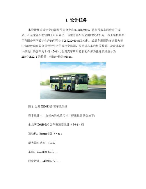
1 设计任务本设计要求设计变速器型号为金龙客车XMQ6931G,该型号客车已经有了成品,在金龙客车的官网上可以查出,该型号客车所采用的发动机为广西玉柴机器集团有限公司所设计生产的型号为YC6J220-30的发动机,成品车采用的变速器为綦江齿轮传动有限公司设计生产的五档变速箱,根据成品车的相关数据,决定本设计中拟设计的客车为6档(5+1),金龙汽车所用轮胎配件多为佳通品牌型号为255/70R22.5的轮胎,轮胎外径为938mm。
图1 金龙XMQ6931G客车效果图在本设计中,由相关的成品尺寸,得出设计参数如下:金龙牌XMQ6931G客车变速器设计(5+1)档发动机: Memax=800 N·m ;最大输出功率:162Kw车速:Vmax=90 Km/h ;额定转速:n=2500r/min ;车轮滚动半径:R0=0.469m ;汽车总质量:9000 Kg ;主减速比:i0=3.33 ;设计要求:采用中间轴式,全同步器换档,要进行齿轮参数设计计算,对一档齿轮的接触强度、弯曲应力进行校核计算。
2 变速器方案选择对于某些轿车和货车的变速器,在较好的路面状况和空载行驶时使用超速档。
采用传动比小于1(0.7~0.8)的超速档,可以更充分地利用发动机功率,降低单位行驶里程的发动机曲轴总转数。
但在本例中鉴于所设计的车辆为载客型客车,因此最高档设为传动比为1的直接档进行工作。
本设计中采用轴式变速器设计,三轴式变速器如图2所示,其第一轴的常啮合齿轮与第二轴的各档齿轮分别与中间轴的相应齿轮相啮合,且第一、第二轴同心。
在传递动力过程中将第一、第二轴直接连接起来传递扭矩称为直接档,在这种情况下,齿轮、轴承及中间轴均不承载,而第一、第二轴直接传递转矩。
直接档的传递效率高,磨损及噪音也最小,这是三轴式变速器优势所在,易于在良好的路况下节约燃油。
其他前进档需依次经过两对齿轮传递转矩。
因此,在齿轮中心距(影响变速器尺寸的重要参数)较小的情况下仍然可以获得大的一档传动比,这是三轴式变速器的另一主要优势。
无级变速器设计说明书
目录第1章绪论....................................................1.1无级变速器的简介............................................1.2无级变速器的分类............................................1.3机械无级变速器..............................................1.3.1机械无级变速器的发展概况1.3.2机械无级变速器的分类 .............................................1.3.3机械无级变速器的应用第2章变速器设计方案及论证 .....................................2.1变速器的设计要求............................................2.2变速器设计方案论证..........................................2.2.1传动方案2.2.2方案的分析第3章变速器主要参数的设计计算 .................................3.1电机的选择..................................................3.2齿轮的设计..................................................3.2.1齿轮的设计要求3.2.2齿轮的相关参数计算3.3轴的直径的确定..............................................3.4轴承的设计..................................................3.5键的设计....................................................3.6联轴器的选择3.7设计零件的校核3.7.1轴的校核3.7.2轴承的校核3.8箱体的设计..................................................第4章变速器的润滑与密封 .......................................第5章变频器的调控分析5.1变频器的简介5.2变频器对电机的控制第6章结论.....................................................参考文献: ........................................................致谢............................................................附录Ⅰ......................................... 错误!未定义书签。
三菱扶桑推出1.5吨载重级轻型Canter卡车的新款手动变速器型号说明书

Nov. 1, 2021 Mitsubishi Fuso launches a new manual transmission model of the 1.5-ton payload class light-duty Canter truckKawasaki, Japan - Mitsubishi Fuso Truck and Bus Corporation (MFTBC), one of Asia’s leading commercial vehicle manufacturers, is pleased to announce that it will add a new manual transmission (MT) model to its light-duty Canter truck. The MT model will be added to Canter trucks with a payload of 1.5 tons. The Canter MT model will be available through MFTBC sales companies and regional sales units across Japan starting from November 2021.MFTBC has newly added the MT model to its 1.5-ton payload class of Canter trucks after 10 years, in response to ongoing needs in the market. Through the automatic transmission (AMT) models that provide a smooth driving experience with the "DUONIC 2.0” 6-speed dual clutch transmission and a 5-speed MT vehicle that provides powerful and flexible maneuvering, the FUSO Canter is able to respond to various requirements on the road.The Canter also now comes with the "Back Eye Camera System” safety feature as an optional setting.* As with the latest Canter models, MFTBC will continue to pursue a safe and comfortable driving experience for customers through continuous product advancements.*The Back Eye Camera System is an optional setting for all models from MFTBC. Please note that the installation requirements will differ depending on the body. For more details, please contact your nearest FUSO sales location.The Canter’s 1.5 tons loading class model (Special vehicle for photo shooting purposes only)Vehicle Specifications and Selling Price in the Tokyo District (including 10% consumption tax) MFTBC at a Glance Based in Kawasaki, Japan, Mitsubishi Fuso Truck and Bus Corporation (MFTBC) is one of Asia's leading commercial vehicle manufacturers, with 89.29% of its shares owned by Daimler Truck AG and10.71% by various Mitsubishi group companies. An icon in the Japanese commercial vehicle industry with a longstanding history of more than 85 years with its Fuso brand, MFTBC manufactures a range of commercial vehicles including light, medium, and heavy-duty trucks and buses, and industrial engines for over 170 markets worldwide. In 2017, MFTBC introduced the eCanter, the first all-electric light-duty truck in series-production and in 2019, the Super Great – Japan’s first heavy -duty truck fitted with Level 2 Automated Driving Support Technology, a benchmark in the Japanese commercial vehicle market. MFTBC operates under the umbrella of Daimler Trucks Asia, together with its partner organization Daimler India Commercial Vehicles (DICV) in India. This strategic unit allows the entities to collaborate on areas such as product development, parts sourcing and production to provide the best value to customers.Follow us on social media:https:///FusoOfficialhttps:///company/10210240/https:///fusoofficial/https:///FusoOfficialhttps:///user/FusoofficialModel Engine Transmission Main Specifications Selling Price in theTokyo District(in ‘000 yen,including 10%consumption tax)2TG-FBA00 4P10 96kW(130PS) 5 speed MT standard single cab 2WD 1.5 tons loading class standard length all low floor standard flat body made of wood3,980. 900。
Invertek Drives Optidrive E3 变速器说明书

/optidrive-e3Offa’s Dyke Business ParkWelshpool, Powys, UKSY21 8JFTel: +44 (0)1938 556868Fax: +44 (0)1938 556869Email:************************INVERTEK DRIVES LIMITED UK HeadquartersGeneral Purpose DriveEasy control for all motor typesAbout Invertek DrivesSales, service & application support in over 80 countriesWorld-class production, innovation & training facilities at UK headquartersGlobal assembly cells controlled by cloud-based manufacturing databaseISO 14001 environmental &ISO 9001 quality management systemsAC Variable Speed DriveOptidrive E3L ow Power ApplicationsDedicated to low power applications, Optidrive E3 combines innovative technology, reliability, robustness and ease of use in a range of compact IP20 & IP66 enclosures.S imple Commissioning14 parameter basic setup. Default settings suitable for most applications. Contactor style connection for simple wiring.O ptidrive E3 IP66Environmentally protected, IP66 rated models can be mounted directly on your processing equipment.W ashdown ReadyWith a sealed ABS enclosure and corrosion resistant heatsink, Optidrive E3 IP66 models are ideal for high-pressure washdown applications.O n-drive ControlIP66 models feature optional, convenient controls for speed control, REV/OFF/FWD and Power ON/OFF, complete with safety lock.S ingle Phase Motor ControlOptidrive E3 for Single Phase Motors provides accurate speed control of single phase PSC or shaded pole motors. Specialboost phase ensures reliable starting, initially ramping the motor voltage up to rated voltage whilst maintaining a fixed starting frequency, before reducing the frequency and voltage to the desired operating point.+44 (0)1938 5568680.37kW – 37kW / 0.5HP – 50HP 110 – 480V Single & 3 Phase InputEasy to UseIP66IP20© 2019 I n v e r t e k D r i v e s L t d . A l l r i g h t s r e s e r v e d . 85-O D E 3B -I N V 2.16For worldwide locations, please visit /worldwide Contact your local representative at /representative Tel: 1-800-SM-CYCLO (762-9256)Operates up to 50°CCompact, robust and reliable general purpose drive for panel mountingSimply Power UpOptidrive E3 provides precise motor control and energy savings using the factorysettings. Simply power up and the drive can immediately deliver energy savings.14 basic parameters allow simple adjustment for your application if required, with up to 50 parameters available in total for a highly flexible performance.IP20Up to 37kWSimple InstallationDIN rail and keyhole mounting optionsQuick ReferenceIntegrated help cardOptistick SmartRapid commissioning toolSee Page 10Fast Connection5mm rising clamp terminalswith captive screws5 sizes cover global supply ratingsIncredibly Easy to UseBuilt in PI control, EMC filter (C1) & brake chopper Application macros for industrial, fan and pump operationconnectivityDual analogue inputsRTUon-board as standardControls Multiple Motor TypesIE2, 3 & 4IM, PM, BLDC and SynRMMotor supply connects at baseDust-Tight DesignInstall directly on your processing equipment and be sure of protection from dust and contaminants.Washdown ReadyWith a sealed ABS enclosure and corrosion resistant heatsink, the Optidrive E3 IP66 is ideal forhigh-pressure washdown applications.Switched modelsSimply wire up the drive, turn the inbuilt potentiometer and the motor will start running – allowing immediate energy savings.Saving energy cannot be easier than this!IP66/Nema 4X outdoor ratedBuilt with tough polycarbonate plastics specifically chosen to withstand degredation by ultra violet (UV), greases, oils and acids. Also robust enough not to be brittle at -20o C.For ultimate ease of useLockable Mains Disconnect / IsolatorLocal Speed Potentiometer Run Reverse / Off / Run Forward SwitchOutdoor rated enclosed drives for direct machine mounting, dust tight and ready for washdown dutyIP66 OutdoorUp to 22kWCoated Heatsink as StandardIdeal for hygiene based operations requiring washdown — such as food and beveragePower supply connects at top123Locally customisableFlat front to terminal cover with mounting points for switches and an internal PCB.2 x RJ45 portseliminate the need for a splitter.Easily accessible EMC disconnect Easy to wiredue to the large, accessible chamber and removeable gland plate.123Switched or non-switchedConformal coating as standardInput RatingsSupply Voltage 110 – 115V ± 10% 200 – 240V ± 10% 380 – 480V ± 10%SupplyFrequency48 – 62HzDisplacementPower Factor> 0.98PhaseImbalance3% Maximum allowedInrush Current< rated currentPower Cycles120 per hour maximum, evenly spacedOutput RatingsOutput Power 110V 1 Ph Input: 0.5–1.5HP (230V 3 Ph Output) 230V 1 Ph Input: 0.37–4kW (0.5–5HP)230V 3 Ph Input: 0.37–11kW (0.5–15HP)400V 3 Ph Input: 0.75–22kW460V 3 Ph Input: 1–30HPOverload Capacity 150% for 60 Seconds 175% for 2.5 secondsOutputFrequency0 – 500Hz, 0.1Hz resolution AccelerationTime0.01 – 600 seconds DecelerationTime0.01 – 600 secondsTypicalEfficiency> 98%Ambient Conditions Temperature Storage: −40 to 60°COperating: −20 to 50°CAltitudeUp to 1000m ASL without deratingUp to 2000m maximum UL approvedUp to 4000m maximum (non UL) Humidity95% Max, non condensing Vibration Conforms to EN61800-5-1Enclosure IngressProtection IP20, IP66Programming Keypad Built-in keypad as standardOptional remote mountable keypadDisplay7 Segment LEDPC OptiTools StudioControlSpecification ControlMethodSensorless Vector Speed ControlPM Vector ControlBLDC ControlSynchronous ReluctancePWMFrequency 4 – 32kHz EffectiveStoppingModeRamp to stop: User Adjustable 0.1 – 600 secsCoast to stopBraking Motor Flux BrakingBuilt-in braking transistor (not frame size 1)Skip Frequency Single point, user adjustableSetpointControlAnalogSignal0 to 10 Volts10 to 0 Volts0 to 20mA20 to 0mA4 to 20mA20 to 4mADigitalMotorised Potentiometer (Keypad)Modbus RTUCANopenEtherNet/IPFieldbusBuilt-inCANopen125–1000 kbpsModbusRTU9.6–115.2 kbps selectableI/O Specification Power Supply24 Volt DC, 100mA, Short Circuit Protected10 Volt DC, 10mA for PotentiometerProgrammableInputs4 Total2 Digital2 Analog / Digital selectableDigital Inputs8 – 30 Volt DC, internal or external supplyResponse time < 4msAnalog InputsResolution: 12 bitsResponse time: < 4msAccuracy: ± 2% full scaleParameter adjustable scaling and offsetProgrammableOutputs2 Total1 Analog / Digital1 RelayRelay Outputs Maximum Voltage: 250 VAC, 30 VDCSwitching Current Capacity: 6A AC, 5A DCAnalogOutputs0 to 10 VoltApplicationFeaturesPI Control Internal PI ControllerStandby / Sleep FunctionFire ModeBidirectionalSelectable Speed Setpoint (Fixed / PI / Analog/ Fieldbus)Maintenance &DiagnosticsFault Memory Last 4 Trips stored with time stampData LoggingLogging of data prior to trip for diagnosticpurposes:Output CurrentDrive TemperatureDC Bus VoltageMonitoring Hours Run MeterStandardsComplianceLow VoltageDirectiveAdjustable speed electrical power drive systems.EMC requirementsEMC Directive2014/30/EUCat C1 according to EN61800-3:2004MachineryDirective2006/42/ECConformance CE, UL, RCMDrive Specification2 221 110 150kW HP Amps Frame110 – 115V ± 10% 1 Phase Input 0.370.5 2.31ODE-3-110023-101#0.751 4.31ODE-3-110043-101#1.1 1.5 5.82ODE-3-210058-104#200 – 240V ± 10% 1 Phase Input 0.370.5 2.31ODE-3-120023-1#1#0.751 4.31ODE-3-120043-1#1#1.5271ODE-3-120070-1#1#1.5272ODE-3-220070-1#4#2.2310.52ODE-3-220105-1#4# 4515.33ODE-3-320153-104#200 – 240V ± 10% 3 Phase Input 0.370.5 2.31ODE-3-120023-301#0.751 4.31ODE-3-120043-301#1.5271ODE-3-120070-301#1.5272ODE-3-220070-3#4#2.2310.52ODE-3-220105-3#4# 45183ODE-3-320180-3#4# 5.57.5243ODE-3-320240-3#4# 7.510304ODE-3-420300-3#4# 1115464ODE-3-420460-3#4# 1520615ODE-3-520610-3F42 18.525725ODE-3-520720-3F42380 – 480V ± 10% 3 Phase Input 0.751 2.21ODE-3-140022-3#1#1.52 4.11ODE-3-140041-3#1#1.52 4.12ODE-3-240041-3#4#2.23 5.82ODE-3-240058-3#4#459.52ODE-3-240095-3#4#5.57.5143ODE-3-340140-3#4#7.510183ODE-3-340180-3#4#1115243ODE-3-340240-3#4#1520304ODE-3-440300-3#4#18.525394ODE-3-440390-3#4#2230464ODE-3-440460-3#4#3040615ODE-3-540610-3F423750725ODE-3-540720-3F42ProductFaModelCodeGenerationVoltageCoFrameSizeOutputCuSupplyPhaEnclosureBrakeTranEMCFilterEnclosure TypesEMC FilterAFB2Replace #colour-coded optionkW HP Amps Size110 – 115V ± 10%1 Phase Input0.370.571ODE -3-110070-1#1#-010.550.7510.52ODE -3-210105-1#4#-01200 – 240V ± 10%1 Phase Input0.370.5 4.31ODE -3-120043-1#1#-010.75171ODE -3-120070-1#1#-011.11.510.52ODE -3-220105-1#4#-01P r od uc tF a M od el C od eG en er a ti o nV o l t a g e C o F r a m e S i z e C a p a c i t y S u p p l y P h a E n c l o s u r e T S i n g l e P h a s B r a k e T r a n s E M C F i l t e r Enclosure TypesAB2Replace #colour-coded optionODE -3-120043-3F 12-01Product Family GenerationFrame Size Capacity 110–115V = 1Voltage Code 200–240V = 2380–480V = 4Model Code Guide:Drive SpecificationInput RatingsSupply Voltage 110 – 115V ± 10%200 – 240V ± 10%Supply Frequency 48 – 62Hz Displacement Power Factor > 0.98Phase Imbalance 3% Maximum allowed Inrush Current < rated currentPower Cycles120 per hour maximum, evenly spaced Output RatingsOutput Power 110V 1 Ph Input: 0.5–0.75HP230V 1 Ph Input: 0.37–1.1kW (0.5–1.5HP)Overload Capacity 150% for 60 Seconds 175% for 2.5 seconds Output Frequency 0 – 500Hz, 0.1Hz resolution Acceleration Time 0.01 – 600 secondsDeceleration Time 0.01 – 600 seconds Typical Efficiency> 98%Ambient ConditionsTemperatureStorage: −40 to 60°C Operating: −20 to 50°CAltitude Up to 1000m ASL without derating Up to 2000m maximum UL approved Up to 4000m maximum (non UL)Humidity 95% Max, non condensing VibrationConforms to EN61800-5-1EnclosureIngress Protection IP20, IP66ProgrammingKeypad Built-in keypad as standardOptional remote mountable keypad Display 7 Segment LED PCOptiTools StudioControl SpecificationControl Method V/F VoltageEnergy Optimsied V/F PWM Frequency 4 – 32kHz EffectiveStopping Mode Ramp to stop: User Adjustable 0.1 – 600 secs Coast to stopBraking Motor Flux BrakingBuilt-in braking transistor (frame size 2)Skip FrequencySingle point, user adjustableSetpoint ControlAnalog Signal0 to 10 Volts 10 to 0 Volts 0 to 20mA 20 to 0mA 4 to 20mA 20 to 4mADigital Motorised Potentiometer (Keypad)Modbus RTU CANopen EtherNet/IPFieldbusBuilt-inCANopen 125–1000 kbpsModbus RTU9.6–115.2 kbps selectableI/O SpecificationPower Supply 24 Volt DC, 100mA, Short Circuit Protected 10 Volt DC, 10mA for Potentiometer Programmable Inputs 4 Total 2 Digital2 Analog / Digital selectableDigital Inputs 8 – 30 Volt DC, internal or external supply Response time < 4msAnalog Inputs Resolution: 12 bits Response time: < 4ms Accuracy: ± 2% full scaleParameter adjustable scaling and offset Programmable Outputs 2 Total1 Analog / Digital 1 RelayRelay Outputs Maximum Voltage: 250 VAC, 30 VDCSwitching Current Capacity: 6A AC, 5A DC Analog Outputs 0 to 10 VoltApplication FeaturesPI Control Internal PI Controller Standby / Sleep FunctionFire Mode Selectable Speed Setpoint (Fixed / PI / Analog / Fieldbus)Maintenance & Diagnostics Fault MemoryLast 4 Trips stored with time stamp Data LoggingLogging of data prior to trip for diagnostic purposes:Output Current Drive Temperature DC Bus Voltage MonitoringHours Run MeterStandards ComplianceLow Voltage Directive Adjustable speed electrical power drive systems.EMC requirementsEMC Directive 2014/30/EU230V 1Ph. Filtered Units : Cat C1 according to EN61800-3:2004Machinery Directive 2006/42/EC ConformanceCE, UL, RCMPallet handling in UK Olive oil decanting in Greece Seed processing in NetherlandsPizza making in Belgium Chamfering machines in Italy Machine tool OEM in UKChemical fume removal in Singapore Sawmill optimisation in UK Precision polishing inSwitzerlandOptions & AccessoriesProven Worldwide in Low Power ApplicationsExternal EMC Filters, Input Chokes & Output Filters are availableSee for detailsCompatible with:Windows Vista & Windows 7, Windows 8, Windows 8.1 & Windows 10Drive commissioning and parameter backup• Real-time parameter editing • Drive network communication• Parameter upload, download and storage • Simple PLC function programming • Real-time scope function and data logging •Real-time data monitoringOptistick SmartRemote KeypadsRJ45 AccessoriesEtherNet ModuleOptiport 2Remote Keypad & LED DisplayOptipad Remote Keypad & TFT DisplayOptistick SmartRapid Commissioning Tool • Allows copying, backup and restore of drive parameters•Provides Bluetooth interface to a PC running OptiTools Studio or the OptiTools Mobile app on a smartphone •Onboard NFC (Near FieldCommunication) for rapid data transferOPT-2-OPORT-INOPT-3-OPPAD-INOPT-3-STICK-INEtherNet Module• ODVA compliant EtherNet/IP Modbus Translator Device• Compatible with all drive platforms: P2, E3 & Eco• Integrated network switch: simplifying network architecture •Compatible with RSLogix and CoDeSys PLCsBusiness-critical climate control for commercial horticulturist Hatziminas Flowers, GreeceChilled water pumpcontrol predicted to save AED 12385 per yearAl Jahili Fort, UAEEfficient water circulation gives energy savings of 60% per annum Leisure World, AustraliaChain wax development for Team Sky cycling team Muc-Off, UKCooling loop for solar energy research Solar Tech Lab, ItalyIdeal for simple and fast connection of Modbus RTU/CAN networksOPT-J4505-IN RJ45 Cable 0.5m OPT-J4510-IN RJ45 Cable 1.0m OPT-J4530-IN RJ45 Cable 3.0m OPT-J45SP-INRS485 3 Way Data Cable Splitter RJ45OPT-2-ETHEG-IN。
轻型货车变速箱设计

摘要发动机的输出转速非常高,最大功率及最大扭矩在一定的转速区出现。
为了发挥发动机的最佳性能,就必须有一套变速装置,来协调发动机的转速和车轮的实际行驶速度。
变速器可以在汽车行驶过程中,在发动机和车轮之间产生不同的变速比,通过换挡可以使发动机工作在其最佳的动力性能状态下。
变速器作为汽车的一个重要组成部分,是用来改变发动机传到驱动轮上的转矩和转速,目的是在原地起步、爬坡、转弯、加速等各种行驶工况下使汽车获得不同的牵引力和速度。
本次设计的变速器是一款手动中间轴式5+1挡机械式变速器。
为了保证轴的刚度要求,将一挡和倒挡布置在变速器的最右边。
换挡机构全部采用同步器进行换挡,变速器采用远程操纵机构,在其上设置了互锁、倒挡锁等一套锁止装置,使驾驶员能够安全、迅速的对变速器操纵,结合总体的要求操纵机构形式选用远程操纵机构形式。
本次设计的变速器即满足了汽车必要的动力性也满足了其经济性的指标。
最后通过对齿轮、轴、键、轴承等的校核,其变速器的尺寸及其部件的强度都满足设计要求。
关键词:变速器,设计,轻型货车,传动比ABSTRACTThe output of the engine speed is very high, maximum power and maximum torque occurs at a certain speed zone. In order to play the best performance of the engine, it must be a variable speed device, to coordinate engine speed and the actual wheel speed. Transmission can be in the car driving the process, between the engine and the wheels have different gear ratio, the engine can work through the shift in the dynamic performance of its best state.Transmission as an important part of the car is used to change the engine reached the driving wheel torque and rotational speed on the aim of starting in place, climbing, cornering, acceleration and other driving situation, vehicle access to the different traction and speed.The transmission is a manual designed for intermediate shaft 5 +1 gear mechanical transmission. To ensure the axial stiffness requirements, the layout of a block and reverse gear in the transmission of the far right. Shifting agencies all use synchronizer for shifting, transmission by remote manipulation of institutions, in their last set, interlocking, reverse gear lock of a locking device so the driver can safely, quickly on the transmission control, combined with the overall requirements of remote manipulation of institutional forms used form of control mechanism. The design of the transmission that is necessary to meet the dynamic nature of the automobile also meet its economic targets. Finally, through the gears, shafts, keys, bearings, etc. checked, the size of its transmission and its components have the strength to meet the design requirements.KEY WORDS:Transmission, Design, Light truck, Speed ratio目录前言 (1)第1章概述 (3)第2章变速器传动机构布置 (4)§2.1 传动机构布置方案分析 (4)§2.2零部件结构方案分析 (10)§2.2.1 齿轮形式 (11)§2.2.2 换挡机构形式 (11)§2.2.3 变速器轴承 (12)第3章变速器主要参数的选择 (14)§3.1中心距A (14)§3.2 齿轮参数的选取 (16)§3.2.1 模数 (16)§3.2.2 齿形、压力角α、螺旋角β和齿宽b (17)§3.2.3 齿轮变位系数的选择原则 (18)§3.3 各挡齿轮齿数的分配及传动比的计算 (18)§3.3.1确定一档齿轮齿数 (19)§3.3.2确定二档齿轮齿数 (20)§3.3.3确定三档齿轮齿数 (21)§3.3.4确定五档齿轮齿数 (21)§3.3.5确定倒档传动比 (22)§3.4 轴的选取 (24)§3.4.1轴尺寸初选 (24)§3.4.2轴的结构形状 (26)§3.4.3轴的受力分析 (27)第4章变速器的设计与计算 (29)§4.1 轴的计算与校核 (29)§4.1.1 中间轴的受力分析 (29)§4.1.2 X-Z弯矩计算: (30)§4.1.3 X-Y面弯矩计算: (31)§4.1.4 合成弯矩 (31)§4.1.5 作力矩图 (31)§4.1.6 校核计算 (33)§4.2齿轮的计算与校核 (34)§4.2.1 齿轮的计算校核公式 (34)§4.2.2 校核中间轴一挡齿轮: (36)§4.2.3 校核第二轴一挡齿轮: (37)§4.2.4 校核第一轴四档常啮合齿轮: (37)§4.2.5 校核中间轴四档常啮合齿轮: (38)§4.2.6 校核中间轴二档齿轮: (39)§4.2.7 校核第二轴二档齿轮: (40)§4.3 轴承的计算与校核 (41)§4.4 键的校核计算 (42)第5章同步器的设计 (43)§5.1 同步器的结构 (43)§5.2 同步环主要参数的确定 (44)第6章变速器操纵机构设计 (47)结论 (49)参考文献 (50)致谢 (51)前言随着汽车工业的不断壮大,以及汽车行业持续快速的发展,如何设计出更经济实惠,工作可靠,性能优良,汽车已经是当前汽车设计者的紧迫问题,也是我们作为汽车工程本科毕业生,必须肩负的重任。
变速器说明书范文
变速器说明书范文本次课业设计是在给定主要整车参数的情况下进行设计,发动机最大功率车轮型号81kw185/60R14S发动机最大转矩110N·m总质量1722kg最大转矩时转速最高车速3200r/min175km/h一变速器主要参数的选择1.1档数的确定近年来,为了降低油耗,变速器的档数有增加的趋势。
目前,乘用车一般用4~5个档位的变速器。
发动机排量大的乘用车变速器多用5个档。
商用车变速器采用4~5个档或多档。
载质量在2.0~3.5t的货车采用五档变速器,载质量在4.0~8.0t的货车采用六档变速器。
多档变速器多用于总质量大些的货车和越野汽车上。
档数选择的要求:1、相邻档位之间的传动比比值在1.8以下。
2、高档区相邻档位之间的传动比比值要比低档区相邻档位之间的比值小。
因此,本次设计的轿车变速器为5档变速器。
1.2传动比范围变速器传动比范围是指变速器最高档与最低档传动比的比值。
最高档通常是直接档,传动比为1.0;有的变速器最高档是超速档,传动比为0.7~0.8。
影响最低档传动比选取的因素有:发动机的最大转矩和最低稳定转速所要求的汽车最大爬坡能力、驱动轮与路面间的附着力、主减速比和驱动轮的滚动半径以及所要求达到的最低稳定行驶车速等。
目前乘用车的传动比范围在3.0~4.5之间,总质量轻些的商用车在5.0~8.0之间,其它商用车则更大。
本设计最高档传动比为0.81。
1.3变速器各档传动比的确定(1)、主减速器传动比的确定发动机转速与汽车行驶速度之间的关系式为[12]:ua0.377rnigi0(3.1)式中:ua——汽车行驶速度(km/h);n——发动机转速(r/min);rig——车轮滚动半径(m);——变速器传动比;i0——主减速器传动比。
已知:最高车速uama某=vama某=175km/h;最高档为超速档,传动比ig=0.81;车轮滚动半径由所选用的轮胎规格185/60R14S得到r=290(mm);发动机转速n=np=7734(r/min);由公式(3.1)得到主减速器传动比计算公式:i00.377nrigua0.377773429100.7516926.44(2)、最抵档传动比计算按最大爬坡度设计,满足最大通过能力条件,即用一档通过要求的最大坡道角ma某坡道时,驱动力应大于或等于此时的滚动阻力和上坡阻力(加速阻力为零,空气阻力忽略不计)[13]。
SL使用说明书(SL-1、SL-...

尊敬的用户:感谢您对英伦汽车的信任,选择了具有优良安全性、舒适性、动力性和经济性的英伦汽车,我们期待着以优质的产品和服务为您的工作和生活带来乐趣。
首次使用前请阅读并遵守本手册的内容,将帮助您更好的了解、使用英伦汽车,使您的新车在今后使用中技术状况良好,始终保持最佳性能。
您对您的车辆了解的越多,就越能享受到驾驶该车辆的安全性和趣味性。
若您在使用过程中发现一些问题,请就近与本公司授权的英伦品牌服务站联系,服务站将在保养、维修方面向您提供优质的服务,请您务必按本手册中的保养规定按期完成保养工作。
本手册提供了所有车型的相关信息,由于车型配置不同,本手册的说明与您所购车辆的实际配置可能会有差别,请以实际接收的车辆为准。
本手册属于整车的一个组成部分,出售或出借本车时,请将本手册转交给新车主。
本手册中的所有资料均为出版时的最新资料,今后如有改动,恕不另行通知。
祝您快乐人生,吉利相伴!浙江吉利控股集团汽车销售公司 2013年07月版权所有。
如未经吉利控股集团汽车销售公司书面同意,不得转载或复印本手册的任何内容。
本 手 册 中 的 重 要 说 明安全和车辆损坏警告本使用说明书中,具有安全警告和车辆损坏警告,必须小心根据警告的内容来避免受伤或损坏的可能性。
不得擅自进行车辆改装,否则将会影响车辆的性能、安全和使用期限,甚至可能触犯政府法规,因改装引起的直接或间接车辆问题均不在保修范围之内。
本书中警示类型的表示和使用方法等说明如下:《车辆使用说明书》与《保修保养手册》是本公司与用户之间就有关产品的正确使用、质量保证责任、售后服务等方面的约定,请务必在使用本公司产品前认真阅读。
若您的汽车或零部件因为过度使用、不正确使用、不按规定的里程、时间间隔进行保养或擅自进行车辆改装而导致故障,您将丧失相应的索赔权利和保修权利。
本使用说明书中的93号无铅汽油适用于除北京地区以外区域,北京地区根据环保要求使用92号无铅汽油。
SL-0001安全符号当看到上图所示的安全标记时,则表示“禁止……”;“禁止这样做”或者“禁止让这种情况发生”。
上汽大众-全新一代朗逸-说明书-使用维护说明书

本说明书适用于下列表中各种型号的上汽大众 AllNew Lavida 全新一代朗逸系列轿车。
用户在使用本公司产品以前,必须认真研读产品使用维护说明书,任何不当的使用、保养和修理都可能导致车辆的损坏及影响质量担保服务。
因此,在使用产品前请认真阅读本使用维护说明书,并对照表中的型号确认您的车型。
名称型号发动机变速箱全新一代朗逸SVW71221AN DJN七挡自动变速器全新一代朗逸SVW71421AL CSS七挡自动变速器全新一代朗逸SVW71521AG DLW五挡手动变速器全新一代朗逸SVW71521BG DLW六挡自动变速器全新一代朗逸SVW71221CN DJN七挡自动变速器全新一代朗逸SVW71421CL CSS七挡自动变速器全新一代朗逸SVW71521EG DLW五挡手动变速器全新一代朗逸SVW71421BT DJS七挡自动变速器全新一代朗逸SVW71421DT DJS七挡自动变速器全新一代朗逸SVW71221BN DLS七挡自动变速器全新一代朗逸SVW71221DN DLS七挡自动变速器全新一代朗逸SVW71521CF DMB五挡手动变速器全新一代朗逸SVW71521GF DMB五挡手动变速器全新一代朗逸SVW71521DF DMB六挡自动变速器全新一代朗逸SVW71221EN DLS七挡自动变速器全新一代朗逸SVW71421ET DJS七挡自动变速器本使用维护说明书描述了该车型车辆在当前范围的配置、功能及操作的一般通用信息,但用户车辆的实际配置和功能等信息以具体交付时的为准。
本公司将持续对各种车型进行改进,各车型在外形、配置、功能和结构设计等方面也可能随时会发生变化,故本公司有权在法律法规允许的范围内对本说明书有关版本进行更改、补充,若用户对此有疑义请及时拨打上汽大众客户服务热线400-820-1111予以咨询。
未经本公司书面同意,不得复制、翻译或摘录本使用维护说明书。
上汽大众汽车有限公司依法保留对本说明书有关版本进行更改、补充等的一切权利。
星氐5A型fan和pump变速器说明书
Fan and Pump AC Drive0.75~30kW(1~40HP) 3-Phase 200~230Volts 0.75~450kW(1~600HP) 3-Phase 380~480Volts 5.5~110kW(7.5~150HP) 3-Phase 525~600VoltsiP5ALS Starvert SV-iP5A has been specifically designedand created to provide competitive solutions for fanand pump applications2Overview Model & TypeStandard Specifications WiringTerminal Configurations (Power Circuit Terminal)Terminal Configurations (Control Circuit Terminal)Programming KeypadProgramming Keypad (Parameter Navigation)Parameter Description Trial Run DimensionsDB (Dynamic Braking) UnitExternal DB Resistor / Peripheral Device48913171922232437394550C o n t e n t sSTARVERTiP5AMarine Type Certification From DNV Specialized Functions for Fan and Pump Energy Saving and High EfficiencyUser-friendly Interface and Easy MaintenanceIntelligent Control Mechanism3Drive Starvert iP5A SeriesSpecialized Functions for Fan and PumpThe iP5A, specifically designed for HVAC application, provides stable and cost-effective system performance.In the centrifugal fan and pump field, PID control is provided as a standard function in order to maintain a constant control of pressure, flow and oil level. This function includes Pre-PID, Sleep and Wake up and output inverse sub-functions.PID ControlWhere external or cascaded PID control is required, the built-in dual PIDalgorithm of the iP5A can be utilized to satisfy various system requirements.Dual PIDMulti Motor Control (0.75~450kW)The iP5A MMC function provides cost-effective, simultaneous control of up to eight motors, without requiring external controllers.Marine Type Certification From DNVThe iP5A has been tested and certified by DNV to comply with International Marine requirements40.750.500.400.250.200.1010203040506070Load %Conventional drive controliP5ADamper controlReduction percentage600RPMV/F30% manual energy saving Automatic energy savingEnergy Saving and High EfficiencyThe iP5A, specifically designed for fan and pump applications, guarantees energy savings by optimizing the system.Load change may incur energy losses but the optimized flux control of iP5A results in more outstanding energy saving compared to previous models.Automatic Energy SavingEnergy savings are obtained through the Sleep and Wake-Up functions of the iP5A, which enable the drive to automatically switch off during user-programmed low-load conditions and then to start up again when process demand increases.Sleep and Wake-up FunctionWhen using the drive in damp conditions, this function protects both the motor and the drive's outputPre Heating FunctionWhen 2 or more fans, or a high inertia load are connected to the drive, the iP5A detects the motor speed after a momentary power failure, enabling the motors to be smoothly reaccelerated without mechanical and electrical shock-loading to the system.Flying Start FunctionPID referencePID feedbackRun commandOutput frequencyWake-up mode Returning to normal stateSleep mode Adjusting output with detecting load(Energy saving)Industrial Drive for Fan and Pump STARVERT iP5A5Drive Starvert iP5A SeriesDuring unexpected power failure conditions, the iP5A can bring the load to a controlled stop, by utilizing the inertial energy. This can prevent further process problems or accidents.Safety StopThis algorithm reduces deceleration time, thereby improving system efficiency.Flux Braking AlgorithmIntelligent ControlBy taking ambient temperature into account, the iP5A can automatically adjust the Carrier (Modulation) Frequency.Automatic Carrier Frequency ChangeThe iP5A has optimized protective functions, such as safety stop and pre-excitation of the motor, amongst others.ProtectionBecause of effectual functions and protection algorithms, the iP5A provides constant performance,in spite of external power fluctuations.During Power Dips or Momentary Power Outage, the drive output can be maintained by utilizing the residual mechanical energy in the load as a regenerative source. The duration of the power-dip ride-through depends on the load characteristics.Improved System Management during Power Dips and Momentary Power OutagesIn spite of external voltage fluctuations and lightning surges, the iP5A optimizes motor performance.Constant and Stable PerformanceUnder damp conditions, leakage currents can occur when using drives. These currents can cause a system failure. The iP5A low-leakage PWM algorithm reduces these leakage currents to ensure reliability of operation.Current Leakage Reduction AlgorithmZero vector Zero vectorValid vector PWM Valid vectorPower failure for 1 secondPower failure for 3 secondsMecha -nical energyLoadMechanical energyConsumed energyE m i t t e d e n e r g yThe mechanical energy stored during blackout can be used for driveユs power.6Easy StartWhen pushing ‘STOP ’ key for 2~3 seconds in case drive turns on, the drive turns into ‘Easy Start Mode ’ with FWD, REV, and STOP command. ‘SHIFT/ESC ’ can return it to previous mode.Control method: V/F Control frequency: JogUser-friendly Keypad & Easy MaintenanceNPN/PNP InputiP5A has both NPN and PNP input, and you can select one of them easily.Abundant I/O SuggestioniP5A serves abundant I/O.Various Units of I/O DisplayThe iP5A display can be calibrated in many different types of process units.Built-in RS485 and Optional CommunicationThe built-In RS485 allows for communication without external option.However, the optional communication boards enable the iP5A to talk to BMS and most Industrial SystemsLong-life Condenser and Simple FrameworkiP5A adopts long-life condenser and enables easy maintenance in simple framework.Consumption Time DisplayiP5A displays consumption time of components so that users can replace them in time.Others•Removable terminal board •External fan available •Cooling fan on/off control3145672384126The iP5A construction allows for easy maintenance, with ease-of-access to all components.579Digital Input/OutputAnalog Input (Voltage + Current)/Output Pulse Input NTC/PTC Input8 points / 4 points (1+1) points /4 points 1 point 1 pointIndustrial Drive for Fan and Pump STARVERT iP5A7Drive Starvert iP5A SeriesSV 055iP5A2NE200~230V Class380~480V ClassMotor Rating0.75kW (1HP)1.5kW (2HP)2.2kW (3HP)3.7kW (5HP)5.5kW (7.5HP) 7.5kW (10HP)11kW (15HP) 15kW (20HP) 18.5kW (25HP) 22kW (30HP) 30kW (40HP) 37kW (50HP) 45kW (60HP) 55kW (75HP) 75kW (100HP) 90kW (125HP) 110kW (150HP) 132kW (200HP) 160kW (250HP)220kW (300HP) 280kW (350HP) 315kW (400HP)375kW (500HP) 450kW (600HP)SV008iP5A-4NE SV015iP5A-4NE SV022iP5A-4NE SV037iP5A-4NE SV055iP5A-4NE SV075iP5A-4NE SV110iP5A-4NE SV150iP5A-4NO SV185iP5A-4NO SV220iP5A-4NO SV300iP5A-4NO SV370iP5A-4O SV450iP5A-4O SV550iP5A-4O SV750iP5A-4O SV900iP5A-4O SV1100iP5A-4OL SV1320iP5A-4OL SV1600iP5A-4OL SV2200iP5A-4OL SV2800iP5A-4OL SV3150iP5A-4O SV3750iP5A-4O SV4500iP5A-4O380~480V Class (Classification)SV055iP5A-4NE (CLASS)SV075iP5A-4NE (CLASS)SV110iP5A-4NE (CLASS)SV150iP5A-4NOL (CLASS)SV185iP5A-4NOL (CLASS)SV220iP5A-4NOL (CLASS)SV300iP5A-4NOL (CLASS)SV370iP5A-4OL (CLASS)SV450iP5A-4OL (CLASS)SV550iP5A-4OL (CLASS)SV750iP5A-4OL (CLASS)SV900iP5A-4OL (CLASS)SV1100iP5A-4OL (CLASS)SV1320iP5A-4OL (CLASS)SV1800iP5A-4OL (CLASS)SV2200iP5A-4OL (CLASS)SV2800iP5A-4OL (CLASS)SV3150iP5A-4O (CLASS)SV3750iP5A-4O (CLASS)SV4500iP5A-4O (CLASS)525~600V ClassSV055iP5A-6SV075iP5A-6SV110iP5A-6SV150iP5A-6SV185iP5A-6SV220iP5A-6SV300iP5A-6SV370iP5A 6SV450iP5A-6SV550iP5A-6SV750iP5A-6SV900iP5A-6SV1100iP5A-6SV008iP5A-2NE SV015iP5A-2NE SV022iP5A-2NE SV037iP5A-2NE SV055iP5A-2NE SV075iP5A-2NE SV110iP5A-2NE SV150iP5A-2NO SV185iP5A-2NO SV220iP5A-2NO SV300iP5A-2NOModel & Type(CLASS)N: No Keypad Input Voltage Motor Rating Series NameClassification8Industrial Drive for Fan and Pump STARVERT iP5AStandard SpecificationsNote 1) Rated capacity (v 3。。V 。。I) is based on 220V for 200V class and 460V for 400V class. 2) Indicates the maximum applicable capacity when using a 4-Pole LS motor. 3) Maximum output voltage will not exceed the input voltage. An output voltage less than the input voltage may be programmed if necessary. 4) IP20/UL Type1 with optional conduit, it can be modified to UL Type1.380~480V Class (0.75~90kW / 1~125HP)200~230V Class (0.75~30kW / 1~40HP)9Drive Starvert iP5A SeriesStandard Specifications525~600V Class (5.5~110kW /7.5~150HP)Note 1) Rated capacity (v 3 X V X I) is based on 220V for 200V class and 460V for 400V class. 2) Indicates the maximum applicable capacity when using a 4-Pole LS motor.3) Maximum output voltage will not exceed the input voltage. An output voltage less than the input voltage may be programmed if necessary.4) IP20/UL Type1 with optional conduit, it can be modified to UL Type1.10Industrial Drive for Fan and Pump STARVERT iP5A(1) Rated capacity (√3×V×I ) is based on 220V for 200V class and 460V for 400V class. (2) Indicates the maximum applicable capacity when using a 4-Pole standard motor.(3) IP20 or UL Enclosed Type1 can be provided by the option. (4) IP20 or UL Enclosed Type1 is not provided.(5) Overload rating 120%, 1 min is based on ambient 25℃Common SpecificationsStandard Specifications Common Specifications (External)Industrial Drive for Fan and Pump STARVERT iP5A WiringFor 0.75~30kW (1~40HP)Note 1) 5G is Common Ground for Analog Input / Output. (Only applied to 0.75 ~ 30kW products)WiringFor 37~90kW (50~125HP) / 315~450kW (400~600HP)Note 1) 5G is Common Ground for Analog Meter Output (SO, S1) and External motor thermal detection (ET). CM is Common Ground for Analog input.Industrial Drive for Fan and Pump STARVERT iP5A For 110~280kW (150~350HP)Note 1) 5G is Common Ground for Analog Meter Output (SO, S1) and External motor thermal detection (ET). CM is Common Ground for Analog input.WiringFor 15~30kW (20~40HP) Built-in DCL TypeFor 37~90kW (50~125HP) Built-in DCL TypeIndustrial Drive for Fan and Pump STARVERT iP5A Terminal Configurations (Power Circuit Terminal)0.75~30kW (1~40HP) <200V/400V/600V Class>37~90kW (50~125HP) / 315~450kW (400~600HP) <400V/600V Class>15~18.5kW (20~25HP) <Built-in DC Reactor Type, 400V Class>22~30kW (30~40HP) <Built-in DC Reactor Type, 400V Class>37~90kW (50~125HP) / 110 ~280kW (150~350HP) <Built-in DC Reactor Type, 400V Class>Note) P1 (+) is not provided for wiring.Terminal Configurations (Power Circuit Terminal) GroundingWires & Terminal lugsIndustrial Drive for Fan and Pump STARVERT iP5ATerminal Configurations (Control Circuit Terminal)0.75~30kW / 1~40HP (200V/400V Class)37~450 kW/50~600HP (400V Class)Terminal Configurations (Control Circuit Terminal)Note) NC terminal is unavailableIndustrial Drive for Fan and Pump STARVERT iP5ASink mode (NPN mode)•Put J1 switch down to set to Sink mode (NPN mode). CM terminal (24V GND) is common terminal for contact signal input.•The factory default is Sink mode (NPN mode).Source mode (PNP mode) Internal Power Supply Used•Put J1 switch up to set to Source mode (PNP mode). Terminal 24 (24V Power Supply) is common terminal for contact input signal.Source mode (PNP mode) External Power Supply Used•Put J1 switch up to set to Source mode (PNP mode).•To use external 24V Power Supply, make a sequence between external Power Supply (-) terminal and CM (24V GND) terminal.iP5A provides Sink/Source (NPN/PNP) modes for sequence input terminal on the control circuit. The logic of the input terminal is settable to Sink mode (NPN mode)/Source mode (NPN mode) by using the J1 switch. Connection method is shown below.Programming Keypad LCD LoaderIndustrial Drive for Fan and Pump STARVERT iP5A Programming Keypad (Parameter Navigation)Parameter group moves directly to DRV group by pressing [SHIFT] key in any parameter code.Parameter Descriptioneither [Speed] (Hz or Rpm), [Percent], [Bar], [mBar], [kPa] or [Pa]. Output Frequency (Hz or Rpm; Unit of outupt speed) is displayed in DRV-00 during the Drive is running. User Unit reference (Unit of PID controller selected) is displayed in DRV-00 during the Drive is not running.2) DRV-15, DRV-18 will appear when APP-02 [Process PI Mode] is set to メYesメ. Also User Unit is displayed when one of I/O-86~ I/O-88 is set to either [Speed](Hz or Rpm), [Percent], [Bar], [mBar], [kPa] or [Pa]. 3)DRV-20 will appear when APP-80 [ExtProcess PI Mode] is set to メYesメ. 4) DRV-91/92 will appear only when DRV-22 is set to [2nd Source].Industrial Drive for Fan and Pump STARVERT iP5AParameter DescriptionFU1-41~48 only displayed when FU1-40 is set to ‘User V/F’.10) Only displayed when FU1-51 is set to ‘Manual’.11) Only displayed when FU1-66 is set to ‘Yes’.31) Only displayed when FU1-75 is set to ‘Yes’.Industrial Drive for Fan and PumpSTARVERT iP5A14) FU2-26 is displayed when FU2-25 [Retry number] is set to [1~10]. 15) FU2-64 is displayed when FU2-60 is set to [Sensorless].Parameter DescriptionFU2-64 is displayed when FU2-60 is set to [Sensorless].Table 1) Switching frequency and fatory default value for each drive capacityIndustrial Drive for Fan and Pump STARVERT iP5AW hen DRV-04 is set to either V1, V1S, I or V1+I or Pulse, only selected item codes are displayed in I/O-1~I/O-19.18) I /O-3,5,8,10,14,16 is displayed 0~100.00 [**] when App-02 is set to [proc PI mode] or APP-80 is set to [Ext PImode] and APP-06 PID Feedback Signal Selection is set to one of I, VI, Pulse, after then, one of I/O-86 ~I/O-88 is set to percentage, Bar, mBar, kPa, Pa except for Speed. Unit will be changed to selected unit. Only user unit displayed when APP-02 or APP-80 is set to [Yes], after APP-06 is set to one of I, V, Pulse, after then one of I/O-86 ~I/O-88 is set to either speed, percentage, Bar, mBar, kPa, Pa..Parameter DescriptionIndustrial Drive for Fan and Pump STARVERT iP5A21) I/O-74 ~ I/O-75 displayed only when one of I/O-76 ~ I/O-79 is set to either FDT-1~FDT5Parameter Description38400 bps can be set only when the external communication option card is installed.23) Only I/O-92 ~ I/O-93 displayed when DRV-03/04 is set to [int485].Industrial Drive for Fan and Pump STARVERT iP5AOnly APP-03 ~ APP-17 displayed when APP-02 is set to [Yes]. Only APP-03 ~ APP-17 and APP-63 ~ APP-65 displayed when APP-2 is set to [Yes].26) If APP-04 Aux Ref Mode is no set, DRV-04 setting will be reference of process PID. And APP -05 setting will be ignored27) If APP-04 is set, APP-04 will appear. And APP -05 setting value will be reference of process PID, DRV-04 setting will be ignored.28) Only APP-20 ~ APP-29 displayed only when one of I/O-20 ~ I/O-27 is set to either 。。2nd Func 。。.O nly APP-40 ~ APP-71 displayed when APP-01 is set to [MMC].30) O nly APP-81 ~ APP-97 displayed when APP-80 Ext PI mode is set to [Yes].Parameter DescriptionIndustrial Drive for Fan and Pump STARVERT iP5A* Only the above EXT group displayed when the corresponding option board is installed.* Refer to the SUB board option manual for details.COM GROUPParameter Description* Only the above COM group displayed when the corresponding option board is installed.* COM-61~66 parameter is used to LonWorks and BACnet communication.Industrial Drive for Fan and Pump STARVERT iP5A Trial RunOperation Example (1)V/F Control + Analog Voltage Input (V1)+ Operation via Terminal (FX/RX)Operation condition•Control mode: V/F control•Frequency command:50 [Hz] analog input via V1 terminal•Accel/Decel time: Accel -15 [sec],Decel -25 [sec]•Drive mode: Run/Stop via FX/RX terminal,Control terminal: NPN modeTrial RunV/F control + Analog input (V1S)+ Operation via terminal FX/RXOperation condition•Control mode: V/F control •Frequency command:Setting 50 [Hz] via Analog input (V1S)•Accel/Decel time: Accel time 15 [sec], Decel time 25 [sec]•Drive mode: Run/Stop via FX/RX,Control terminal: NPN modeIndustrial Drive for Fan and Pump STARVERT iP5A DimensionsSV008~055iP5A (200/400V Class) & SV055~110iP5A (600V Class)SV075~300iP5A (200/400V Class) & SV150~300iP5A (600V Class)DimensionsIndustrial Drive for Fan and Pump STARVERT iP5ASV370~SV550iP5A (400V Class) & SV370~550iP5A (600V Class)41Drive Starvert iP5A SeriesDimensions42Industrial Drive for Fan and Pump STARVERT iP5A SV750, 900iP5A (UL Type 1 or UL Open Type with Conduit Option used, 400V Class)43Drive Starvert iP5A Series44Industrial Drive for Fan and Pump STARVERT iP5ADB (Dynamic Braking) UnitTerminal Configuration•Group 1 -•Group 2 -•Group 3 -CM G POH N NB2GG P/B1B1B2B2B1N P45Drive Starvert iP5A SeriesWiring for DB unit and DB resistor (For 5.5~90kW/7.5~125HP drives)46Industrial Drive for Fan and Pump STARVERT iP5A DB (Dynamic Braking) UnitGroup 147Drive Starvert iP5A SeriesGroup 248Industrial Drive for Fan and Pump STARVERT iP5A DB (Dynamic Braking) UnitGroup 349Drive Starvert iP5A SeriesExternal DB ResistoriP5A do not have built-in DB resistor on power stack as factory installation. External DB Unit and Resistor (Optional) should be installed. See the following table for more details (ED: 5%, Continuous Braking Time: 15 sec). If Enable duty (%ED) is increased to 10%, use external DB resistor having twice Wattage rating.50。
变速器说明书

5+1变速器说明书(总22页)--本页仅作为文档封面,使用时请直接删除即可----内页可以根据需求调整合适字体及大小--车辆与交通工程学院课程设计说明书设计类型专业课程设计设计题目 5+1档变速器设计(有超速档)姓名院系车辆与交通工程学院完成日期指导教师目录第一章机械式变速器方案的确定................................ 错误!未定义书签。
§变速器传动机构布置方案的确定......................... 错误!未定义书签。
§变速器主要参数的选择.................................. 错误!未定义书签。
第二章变速器的设计与计算.................................... 错误!未定义书签。
§轮齿强度计算......................................... 错误!未定义书签。
§轴的计算.............................................. 错误!未定义书签。
§轴上花键的计算....................................... 错误!未定义书签。
第三章变速器同步器的设计.................................... 错误!未定义书签。
§同步器的结构......................................... 错误!未定义书签。
§同步环主要参数的确定................................. 错误!未定义书签。
第四章变速器的操纵机构...................................... 错误!未定义书签。
第五章润滑与密封............................................ 错误!未定义书签。
MR510变速器的使用说明书

把动力传递到每一处 把动力传递到每一处
重庆青山工业有限责任公司
正确使用变速器的要求
正确合理地操作使用变速器,定期进行维护 保养,对于保证汽车安全可靠的行驶和延长变速 器寿命十分重要,需要遵循下面使用要求: 1.润滑油的使用: 变速器使用前必须注入润滑油。 加注油量1.2~1.3L。 润滑油牌号:75W/90-GL-5GB13895-92。 2.正确的油面位置:要确保油面与油面观察口 平齐。油面高度由壳体侧面的油面观察口检查, 油面注至孔口处出现溢出即可。
把动力传递到每一处 把动力传递到每一处
重庆青山工业有限责任公司
下列情况中的任何一种都能引起变速器的工 作温度超过120°C: (1). 发动机转速高。(2).环境温度高。 (3).大功率超速运转。 7.工作倾斜角:变速器的工作倾斜角不得超过 15°,超过15°时,润滑可能不充分(工作倾斜 角等于变速器在底盘上的安装角加上斜坡角度)。
备注:1) 变速器换档操作应在该公里数范围内进行。 2) 变速器匹配不同整车时各档位适合的公里数不同。
把动力传递到每一处 把动力传递到每一处
重庆青山工业有限责任公司
换档原则
1)在整车前进状态下,变速器换档原则上要求 如下:增速换档应由1至5档逐级换档;减速换档应由 5至1档逐级换档;前进状态下,禁止挂倒档。在整车 换档条件下,以免误操作,变速器设有不许5档到倒 档的锁止装置。 2) 挂倒档原则上要求在整车静止下进行;当在 行驶状况下,需要挂倒档时,务必停车3~5s后才能 挂倒档,不得在前进状态下挂倒档;同时,也不得在 倒车状态下挂前进档中的档位。 备注:整车运行时,在紧急情况下,可以不遵守 变速器逐级换档的换档原则。
把动力传递到每一处 把动力传递到每一处
重庆青山工业有限责任公司
变速器设计说明书

设计结论表明,变速器齿轮及各轴尺寸确定,各轴强度的校核满足设计要求,设计结构合理。
关键词:变速器;齿轮;中间轴;同步器
Abstract
Transmission is a transmission device which can fix or change gear ratio at the output shaft and the transmission input shaft, also known as the gearbox, transmission is one of the most important components.
This design is a manual transmission gearbox ofmedium truck.A scheme of structure with three shafts, five (5+1) shifts andLocking pin type synchronizerwas adopted here,combine to pour to block wheel gear and stir fork to carry on a reasonable decoration.The first and second shafts were arranged in line. This kind of structure reduces the gearbox dimension in the axis direction,in assurance block to count under the constant circumstance, decrease wheel gear number.Therefore makes the designed transmission gearbox more compact.
UK-DoC AC15-20系列变速器产品说明书

UK Declaration of ConformityDocument No:DOC-0024-10-A Manufacturer:Parker Hannifin Manufacturing Germany GmbH & Co.KG Electric Motion & Pneumatic Division Address: Robert-Bosch-Str. 22, 77656 Offenburg, GermanyWe hereby declare under our sole responsibility that the below productsType of Product: Variable Speed Drives - Series AC15 and AC20Product Name:15G, 20G and 20F Further Details: See appendix (which is part of this declaration, when attached)fulfill the provisions of following UK legislations including their amendments in force at the time of the declaration: Reference Title SI 2016 No. 1091Electromagnetic Compatibility Regulations 2016 (EU equivalent: 2014/30/EU) SI 2008 No. 1597 Supply of Machinery (Safety) Regulations 2008 - Schedule 2/Annex IV (EU equivalent : 2006/42/EC - Appendix IV) SI 2012 No. 3032 Restriction of the Use of Certain Hazardous Substances in Electrical and Electronic Equipment 2012 (EU equivalent: 2011/65/EU + delegated (EU) 2015/863) SI 2021 No. 745 The Ecodesign for Energy-Related Products and Energy Information Regulations 2021, laying down ecodesign requirements for electric motors and variable speed drives pursuant to SI 2010 No. 2617 (EU equivalent: (EU) 2019/1781 pursuant to 2009/125/EC )Relevant designated standards applied, are:Reference EditionEN 61800-3 2018EN ISO 13849-1 2015EN 61800-5-1 2007+A1:2017+A11:2021EN 61800-5-2 2017 EN IEC 63000 2018 EN 61800-9-2 2017Notes:These products must be installed and operated with reference to the instructions in the product manual. All instructions, warnings and safety information of the product manual must be adhered to.The products are components to be incorporated into machinery and may not be operated alone. The completemachinery or installation may only be put into service when the safety considerations of the Supply of Machinery (Safety) Regulations 2008 are fully adhered to.UKCA mark first applied: 2023-04 (CE mark first applied: 2023-04)Signed for and on behalf of:Parker Hannifin Manufacturing Germany GmbH & Co.KG Location, date of issue: Offenburg, 2023-04-25Division Operational Manager EMPD Timothy Faillo Division Engineering Manager EMPD Timothy Faillo Digital unterschrieben von Timothy Faillo Datum: 2023.05.13 13:59:11 +02'00'Appendix: Product Lists Anhang: Produktlisten。
DFL1160BX5系列使用手册KW3[1].KW5.KG8HH1204(view)教程
![DFL1160BX5系列使用手册KW3[1].KW5.KG8HH1204(view)教程](https://img.taocdn.com/s3/m/98975803aaea998fcc220e69.png)
郑重声明
如果发生下述行为,东风汽车有限公司将不对汽车产品的可靠性、安 全性或适应性承担责任。 1. 车辆铭牌与本公司签发的整车或底盘合格证,同实物不相符或涂改者。 2. 未按照本手册的要求对车辆进行正确使用和规范操作。 3. 未按本手册的规定在服务站进行定期保养 (包括走合保养和里程保
活塞式弹簧制动气室的解除方法 .... 54 附件系统 ............................................ 55 杂物盒 ................................................ 57 收放机 ................................................ 60 综合报警器 ........................................ 64 多功能蜂鸣器 .................................... 64 中央配电盒 ........................................ 65 方向盘的调整 .................................... 68 拖钩 .................................................... 68 前面罩 ................................................ 69 灭火器 ................................................ 69 添加燃油 ............................................ 70 三角警示牌 ........................................ 70 后防护栏 ............................................ 70 驾驶室翻转 ........................................ 71 手动驾驶室翻转操作 ........................ 71 SCR 后处理系统 ............................... 72 OBD 诊断接口 ................................... 73
- 1、下载文档前请自行甄别文档内容的完整性,平台不提供额外的编辑、内容补充、找答案等附加服务。
- 2、"仅部分预览"的文档,不可在线预览部分如存在完整性等问题,可反馈申请退款(可完整预览的文档不适用该条件!)。
- 3、如文档侵犯您的权益,请联系客服反馈,我们会尽快为您处理(人工客服工作时间:9:00-18:30)。
车辆与交通工程学院课程设计说明书设计类型专业课程设计设计题目 5+1档变速器设计(有超速档)姓名院系车辆与交通工程学院完成日期2016.3.18指导教师目录第一章机械式变速器方案的确定................................................................ 错误!未定义书签。
§1.1 变速器传动机构布置方案的确定............................................... 错误!未定义书签。
§1.2变速器主要参数的选择................................................................ 错误!未定义书签。
第二章变速器的设计与计算........................................................................ 错误!未定义书签。
§2.1 轮齿强度计算............................................................................... 错误!未定义书签。
§2.2轴的计算........................................................................................ 错误!未定义书签。
§2.3 轴上花键的计算........................................................................... 错误!未定义书签。
第三章变速器同步器的设计........................................................................ 错误!未定义书签。
§3.1 同步器的结构............................................................................... 错误!未定义书签。
§3.2 同步环主要参数的确定............................................................... 错误!未定义书签。
第四章变速器的操纵机构............................................................................ 错误!未定义书签。
第五章润滑与密封........................................................................................ 错误!未定义书签。
§5.1润滑................................................................................................ 错误!未定义书签。
§5.2 密封............................................................................................... 错误!未定义书签。
第六章心得体会与参考文献........................................................................ 错误!未定义书签。
任务书已知参数:发动机:型号4G22D4最大功率(kw/r/min):105/5400最大扭矩(Nm/r/min):205/4000-4400整车最大总质量:2000kg最高车速:180km/h选取轮胎型号为185/60R1484S,计算得滚动半径为0.289m变速器传动机构布置方案一、传动机构布置方案分析根据设计任务书所给数据可知本次设计为乘用车,设计该车驱动形式为发动机前置后轮驱动,因此选用中间轴式变速器。
变速器第一轴的前端经轴承支承在发动机飞轮上,第一轴上的花键用来装设离合器的从动盘,而第二轴的末端经花键与万向节连接。
如下图为本次设计中间轴式“5+1”(含超速挡)的变速器传动方案。
其传动路线如下:1挡:一轴→1→2→中间轴→10→9→9、11间同步器→二轴→输出2挡:一轴→1→2→中间轴→8→7→5、7间同步器→二轴→输出3挡:一轴→1→2→中间轴→6→5→5、7间同步器→二轴→输出4挡:为直接挡,即一轴→1→1、3间同步器→二轴→输出5挡:一轴→1→2→中间轴→4→3→1、3间同步器→二轴→输出倒挡:一轴→1→2→中间轴→12→13→11→9、11间同步器→二轴→输出变速器传动方案1)倒挡布置方案采用直齿滑动齿轮方式换倒挡,参考《汽车设计》倒挡布置方案,选用图3-5 f)所示倒挡方案。
变速器中的倒挡设置,要求在挂倒挡时需克服弹簧所产生的力,用来提醒驾驶员注意,综合考虑倒挡的中间齿轮位于变速器的左侧或右侧对倒挡轴的受力状况影响,参考图3-6 b)。
二、零、部件结构方案分析1)齿轮形式变速器中的常啮合齿轮均采用斜齿圆柱齿轮,直齿圆柱齿轮仅用于倒挡。
2)换挡机构形式本次设计中,倒挡用直齿滑动齿轮换挡,其余各挡均采用同步器换挡形式。
3)自动脱挡为解决自动脱挡问题,除在工艺上采取措施外,在结构上采取如下方案:将啮合套齿座上前齿圈的齿厚切薄(切下0.4mm),这样,换挡后啮合套的后断面被后齿圈的前端面顶住,从而阻止自动脱挡。
4)变速器轴承变速器的第二轴前端支承在第一轴常啮合齿轮的内腔中,内腔尺寸足够时可布置圆柱棍子轴承,若空间不足则采用滚针轴承。
第二轴后端采用球轴承,用来承受轴向力和径向力。
变速器第一轴前端支承在飞轮的内腔里,因有足够大的空间,故采用一端有密封圈的球轴承来承受径向力,为了保证轴承有足够的寿命,选用能承受一定轴向力的无保持架的圆柱滚子轴承。
变速器第一轴、第二轴的后部轴承,以及中间轴前后轴承,按直径系列一般选用中系列的球轴承或圆柱滚子轴承。
轴承的直径根据变速器中心距确定,并要保证壳体后壁两轴承孔之间的距离不小于6~20mm。
变速器主要参数的选择1)挡数已知,为“5+1”(含超速)挡。
2)传动比范围选取超速挡五挡的传动比为0.8。
初选传动比:05max 377.0u i i r n g p a ⋅⋅= 选取8.05=g i (0.7~0.8)由pe e n p T maxmax 9550⋅=α得854.58132052.110495509550maxmax=⨯⨯=⋅=e e p T p n αr/min 故399.41808.0289.0854.5813377.0377.0max50=⨯⨯⨯=⋅⋅=a g p u i r n i式中:m ax a u ——汽车行驶速度(km/h );p n ——发动机转速(r/min ); r ——车轮滚动半径(m ); 5g i ——变速器最高挡传动比;0i ——主减速器传动比;α ——转矩适应系数,取为1.2;选择最低挡传动比时,应根据汽车最大爬坡度、驱动轮与路面的附着力、汽车的最低稳定车速以及主减速比和驱动轮的滚动半径等来综合考虑、确定。
汽车爬陡坡时车速不高,空气阻力可忽略,则最大驱动力用于克服轮胎与路面间的滚动阻力及爬坡阻力。
故有:1°根据最大爬坡度确定1挡传动比:)sin cos (max max 10max ααη+≥f G ri i T Tg e式中:G ——车辆总重量(N);f ——坡道面滚动阻力系数(对沥青路面μ=0.011~0.017);max e T ——发动机最大扭矩(N ·m); 0i ——主减速器传动比;g i ——变速器传动比;t η ——为传动效率,取为0.9(0.9~0.92); r ——车轮滚动半径;max α——最大爬坡度(实际上轿车的最大爬坡能力常大30%,故在此取为20°)由上式得到:Te g i T rG f G i ηαα0max max max 1)sin cos (+≥代入数据得546.29.0399.4205289.0)20sin 20cos 0165.0(1020001=⨯⨯⨯+⨯⨯⨯≥ g i2°根据驱动轮与路面附着力确定1挡传动比z Tg e F ri i T ⋅≤⋅⋅⋅φη01max 取φ=0.6,G F z %70=得到991.2%90399.4205200007.06.0289.00max 1=⨯⨯⨯⨯⨯=⋅⋅⋅⋅≤T e z g i T F r i ηφ由上述两个条件综合得991.2546.21≤≤g i ,取8.21=g i 校核最大传动比5.38.08.251==g g i i ,符合要求的0.3~4.5 其他各挡的传动比确定:按等比级数原则有294.18.24==q则8.21=g i ,167.2294.1332===q i g ,674.123==q i g ,294.14==q i g (直接挡传动比取为1)8.05=g i3) 中心距(总体要求取大些)中间轴式变速器中心距A 的确定,初选中心距A ,根据下述经验公式计算31max g e A i T K A η=式中:A ——变速器中心距(mm );A K ——中心距系数,乘用车A K =8.9~9.3,取9=A K .0; max e T ——发动机最大输出转距为205(N ·m ); 1i ——变速器一档传动比为2.8;g η ——变速器传动效率,取96%。
=A 9.0396.08.2205⨯⨯⨯=73.79 mm初取A =74mm 。
4) 外形尺寸变速器壳体的轴向尺寸为222743=⨯mm 。
5) 齿轮参数 1°模数由《汽车设计》表3-1和表3-2选取一挡齿轮和倒挡齿轮的法向模数mm ,其余为2.75mm 。
变速器接合齿模数也取为2.75mm 。
2°压力角α变速器齿轮压力角为20°,啮合套或同步器的接合齿压力角取为30°。
3°螺旋角β由于乘用车注重工作平稳和噪声低的特点,故选用较大的螺旋角,使齿轮啮合的重合度增加,但从提高高抵挡齿轮的抗弯强度出发,并不希望用过大的螺旋角,以15°~25°为宜。
斜齿轮传递转矩时,要产生轴向力并作用在轴承上。
这就力求使中间轴上同时工作的两对齿轮产生的轴向力平衡,以减小轴承负荷,提高轴承寿命。