8--欧科佳CAN总线控制系统用户手册
欧科佳CAN总线

1、严禁用手触摸MultIC模块和IOU模块上的引脚; 2、严禁打开和冲洗仪表MultIC模块和IOU模块; 3、当车辆上的电瓶电量不足而无法起动发动机时,请先更换电量充沛的电瓶,然后检查确认 电路正确连接且牢固可靠,方可起动发动机。严禁采用搭接外加电瓶的方式起动发动机。 4、进行电焊工作时必须将IOU模块和仪表上的线束插接器取下
欧科佳总线系统模块安装要求
1、 MULTIC仪表模块的安装位置必须保证仪表内部印刷电路板不会接触到水滴; 2、 MULTIC仪表模块的安装要便于维护,方便信号的检查; 3、 将MULTIC仪表安装到仪表台上时,拧固定螺丝的螺丝刀扭力需设定为2±0.1Nm; 4、 仪表台与MULTIC仪表的结合部分需要尽量平整,有不平整的地方会引起受力不均而碎裂; 5、 在安装MULTIC仪表时禁止跌落; 6、 前部SCC模块要求安装在仪表台右侧电器仓内或司机背后电器仓内,顶部SCC模块要求安装在司机顶部维修风道 内,中部SCC模块要求安装在行李仓维修仓内,后部SCC模块要求安装在车辆最后一排座椅后部或后部电器 仓内; 7、 SCC模块的布置应便于模块的散热、接插件插拔顺畅和提供足够的维护空间; 8、 SCC模块禁止安装在发动机排气系统附近; 9、 SCC模块禁止浸泡在水中使用; 10、 使用4个螺丝固定SCC模块,力矩为10N/m; 11、 SCC模块应垂直安装,25针接插件的开口侧向下; 12、 传感器与SCC模块间的连线应尽可能的短,并且远离大电流信号;
13、 SCC模块连接的导线电阻值应满足要求:9A 输出<0.6 欧姆, 3.2A 输出<3 欧姆, 2A 输出< 6 欧姆, 传感器 地线<1欧姆;
14、 SCC模块上所有的接插件都必须正确装配到位,以确保SCC的防护效果; 15、 总线系统诊断接口必须按图纸定义预留;
Bosch_CAN用户手册中文版

1. C_CAN用户手册1术语和缩写Terms and AbbreviationsThis document uses the following terms and abbreviations.这个文档使用到以下的术语和缩写。
Term MeaningCAN Controller Area Network控制器局域网BSP Bit Stream Processor位流处理器BTL Bit Timing Logic位时间机制CRC Cyclic Redundancy Check Register循环冗余码校验冗余DLC Data Length Code数据长度编码EML Error Management Logic错误管理机制FSM Finite State Machine有限动作状态TTCAN Time Triggered CAN 时间触发通讯的控制器局域网2. C_CAN用户手册2Functional Description功能简介C_CAN是可以作为单独或集成ASIC一部分的CAN总线模块。
用硬件描述语言描述C_CAN综合到逻辑器件。
它包含CAN内核、消息RAM、消息处理状态机、控制寄存器和模块接口。
CAN内核通信符合CAN协议规范2.0A和2.0B。
在使用中位速率可以编程达到1M/S。
硬件连接物理层需在接收发射器。
在CAN网络中通信,每个消息目标需要设定,接收的消息目标和识别符掩码存储到消息RAM中。
所有关于消息处理是在消息处理状态器中完成。
这些功能包括消息过滤、CAN内核与消息RAM之间的通信和消息发送中断请求并产生中断模块。
C_CAN中的寄存器组可以通过接口模块被外器CPU访问。
这些寄存器用于控制或配置CAN内核和消息处理状态机,并存储到消息RAM。
在C_CAN模块中的接口模块可以定制成适合于用户使用的模块接口。
C_CAN具有以下的功能特性:支持CAN协议怎版本2.0A和版本2.0B位速度达到1M/S32个消息目标(在消息RAM中有32个可以自定义接收或发送的消息目标)每个消息目标有自己的识别符掩码可编程的FIFO模式(消息目标在FIFO中连续存放)可屏蔽中断对于时间触发的CAN应用可以取消自动重传模式在自己测试操作可以设计成循环模式(重复发关这一个消息)兼容摩托罗拉公司HC08的8位单处理模块接口对ARM内核有2个16位的接口模式给AMBA ABB总路线3. C_CAN用户手册3模式结构Block DiagramCAN CoreCAN内核CAN协议控制器和接收与发送移位寄存器完成消息的并行或串行转换Message RAM消息RAN存储消息目标和识别符掩码Registers寄存器所有寄存器用于控制和配置C_CAN模块Message Handler消息状态处理机控制数据在CAN内核接收与发送移位寄存器与消息RAM 之间的传送,也在控制和配置寄存器中产生中断Module Interface模块接口到目前为止,C_CAN模块被分成3种不同的接口。
欧科佳总线系统-公交培训20090514

上海公交方案 配置方案1 配置方案1 结构示意图
安装位置
上海公交方案 配置方案2 配置方案2 结构示意图
安装位置
功能介绍 配置方案1 配置方案1
•欧IV发动 水温信息 转速信息 油压信息 尿素液位 故障诊断 瞬时油耗 累计油耗 •缓速器 工作指示灯 •集中润滑 信号指示 •ABS 工作指示灯 故障信息 ASR指示 •油量传感器 油量显示 •空调 故障代码 •自动变速箱 总线档位信号 总线轴速
•输入输出模块防护等级为IP65,具有很好的防水、 输入输出模块防护等级为IP65,具有很好的防水、 输入输出模块防护等级为IP65 防尘、防震等性能,同时具有很好的抗电磁干扰能力, 防尘、防震等性能,同时具有很好的抗电磁干扰能力, 可在恶劣环境下正常工作 •燃油经济性显示 燃油经济性显示 •欧4发动机尿素液位显示 欧
显示 指示信息
通信网络
两路CAN接口: 两路CAN接口: CAN接口 -控制内部车身模块; 控制内部车身模块; -连接底盘CAN网络,兼容SAE J1939协议; 连接底盘CAN网络,兼容SAE J1939协议 CAN网络 协议;
•MultIC CWF1是在 MultIC CWF1是在 欧洲成熟产品基础上 开发的适合中国国情 的第四代CAN CAN总线仪 的第四代CAN总线仪 表。它是控制系统的 核心单元, 核心单元,分析处理 信息,发出指令, 信息,发出指令,显 示CAN总线上各设备 CAN总线上各设备 工作状况。 工作状况。具有强大 故障诊断功能, 故障诊断功能,让您 在最快时间内知道故 障及原因, 障及原因,增加了行 车安全性。 车安全性。
8--欧科佳CAN总线控制系统用户手册
制作者
日期
版本记录
说明
2007.9 2007.4
附录更新 首次发行
Hanmo
Hu Digitally signed by Hanmo Hu DN: cn=Hanmo Hu, c=CN, o=ACTIA CHINA, ou=ACTIA Group, email=hanmo.hu@actia. Date: 2007.09.19 09:40:49 +08'00'
编号 1002340 页数 0 / 21
版本 1
格式A4
上海
文件号: 1002340 版本: 1
1
欧科佳(上海)汽车电子设备有限公司
CAN总线控制系统 用户手册
上海市松江区九亭镇松江高科技园区九泾路128号5号楼B座 邮编:201615
电话: 021-3763 9808 传真: 021-3763 3360 网址:
© 2007 禁止任何未经ACTIA书面同意部分或完全复制使用本文件
Digitally signed by Jingzhang LIU
Jingzhang LIU DN: CN = Jingzhang LIU, C = CN, O = ACTIA, OU = Engineering Date: 2007.09.19 11:36:46 +08'00'
Digitally signed by Jingzhang LIU
7
各符号涵义
1
2 3 4567
8
9
10 11 12 13 14 15
16
17
彩色TFT 液 晶显示屏
18 19
20 21
22
23
Altinex CNK200 Cable-Nook Interconnect Box 用户指南说明书
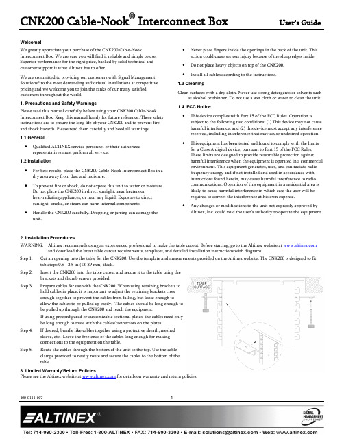
CNK200 Cable-Nook® Interconnect Box User’s Guide400-0111-0071Welcome!We greatly appreciate your purchase of the CNK200 Cable-Nook Interconnect Box. We are sure you will find it reliable and simple to use. Superior performance for the right price, backed by solid technical and customer support is what Altinex has to offer.We are committed to providing our customers with Signal Management Solutions® to the most demanding audiovisual installations at competitive pricing and we welcome you to join the ranks of our many satisfied customers throughout the world.1. Precautions and Safety WarningsPlease read this manual carefully before using your CNK200 Cable-Nook Interconnect Box. Keep this manual handy for future reference. These safety instructions are to ensure the long life of your CNK200 and to prevent fire and shock hazards. Please read them carefully and heed all warnings.1.1 General∙Qualified ALTINEX service personnel or their authorized representatives must perform all service.1.2 Installation∙For best results, place the CNK200 Cable-Nook Interconnect Box in a dry area away from dust and moisture.∙To prevent fire or shock, do not expose this unit to water or moisture.Do not place the CNK200 in direct sunlight, near heaters orheat-radiating appliances, or near any liquid. Exposure to directsunlight, smoke, or steam can harm internal components.∙Handle the CNK200 carefully. Dropping or jarring can damage the unit.∙Never place fingers inside the openings in the back of the unit. This action could cause serious injury because of the sharp edges inside.∙Do not place heavy objects on top of the CNK200.∙Install all cables according to the instructions.1.3 CleaningClean surfaces with a dry cloth. Never use strong detergents or solvents such as alcohol or thinner. Do not use a wet cloth or water to clean the unit.1.4 FCC Notice∙This device complies with Part 15 of the FCC Rules. Operation is subject to the following two conditions: (1) This device may not cause harmful interference, and (2) this device must accept any interference received, including interference that may cause undesired operation.∙This equipment has been tested and found to comply with the limits for a Class A digital device, pursuant to Part 15 of the FCC Rules.These limits are designed to provide reasonable protection againstharmful interference when the equipment is operated in a commercial environment. This equipment generates, uses, and can radiate radiofrequency energy and if not installed and used in accordance withinstructions found herein, may cause harmful interference to radiocommunications. Operation of this equipment in a residential area islikely to cause harmful interference in which case the user will berequired to correct the interference at his own expense.∙Any changes or modifications to the unit not expressly approved by Altinex, Inc. could void the user’s authority to operate the equipment.2. Installation ProceduresWARNING: Altinex recommends using an experienced professional to make the table cutout. Before starting, go to the Altinex website at and download the latest table cutout requirements, templates, and detailed installation instructions with diagrams.Step 1. Cut an opening into the table for the CNK200. Use the template and measurements provided on the Altinex website. The CNK200 is designed to fit tabletops 0.5 - 3.5 in (13-89 mm) thick.Step 2. Insert the CNK200 into the table cutout and secure it to the table using thebrackets and thumb screws provided.Step 3. Prepare cables for use with the CNK200. When using retaining brackets tohold cables in place, it is important to adjust the retaining brackets closeenough together to prevent the cables from falling, but loose enough toallow the cables to be pulled up easily. The cables should be long enough tobe pulled up through the CNK200 and reach the equipment.If using preconfigured or customizable sectional plates, the cables need onlybe long enough to mate with the cables/connectors on the plates.Step 4. If desired, bundle like cables together using a protective sheath, meshedsleeve, etc. Leave the free ends of the cables long enough for makingconnections to the equipment on the table.Step 5. Route the cables through the bottom of the unit to the top. Use the cableclamps provided to neatly route and secure the cables to the bottom of thetable.3. Limited Warranty/Return PoliciesPlease see the Altinex website at for details on warranty and return policies.4. Technical SpecificationsSpecifications are subject to change. See for up-to-date information. Features/Description CNK200 InputsVideo/Audio n/aOutputsVideo/Audio n/aCompatibilityCable-Nook Standard and Customizable Plates CN5000 Series,CNK-IP-100 SeriesSnap-In Connectors All Altinex Snap-In ConnectorsAccessories IncludedMounting Hardware Thumb Screws (2), Mounting Brackets (2)Table 1. CNK200 General Mechanical CNK200 Hole Sets 23Minimum Table Thickness 0.5 in (13 mm)Maximum Table Thickness 3.5 in (89 mm)Housing DimensionsHeight 4.7 in (119 mm)Width 6.0 in (153 mm)Depth 4.7 in (119 mm)Bezel Dimensions (surface)Width 7.9 in (200 mm)Depth 6.5 in (166 mm)Color: CNK200CNK200SBlackBrushed AluminumMaterial Aluminum T︒ Operating 10︒C-35︒CT︒ Maximum 50︒CHumidity 90% non-condensingMTBF (calculations) 40,000 hrs (min.)Table 2. CNK200 Mechanical5. About Your CNK200Installs easily into tabletopConvenient access to cablesSimple, cost-effective interconnect solutionFits table surfaces 0.5 - 3.5 in (13 - 89 mm) thickThe CNK200 is a simple, effective way of hiding/storing multimedia cables and connectors and is designed for boardrooms and conference rooms. Cables remain connected to a presentation system enabling the user to access connections to AC power, video, audio, and other media sources.The cables connected to the presentation system underneath the surface can be accessed from the CNK200 by either pulling the cables up and out of the top of the unit (using retaining brackets) or by plugging external cables into sectional plates installed in the CNK200.Retaining brackets secure cable ends where the brackets can be adjusted to fit a wide variety of cable sizes. Cables are pulled out from the top of the CNK200 when needed and then fed back down under the table when no longer required. The weight of the cables helps to feed the slack through the unit and the cable ends are kept from falling by the retaining brackets.The CNK200 sectional plates allow for diverse connector configurations. Available plates include combinations of audio, video, computer, and AC power connectors, providing extensive flexibility in a convenient package. The sectional plates connect permanently to the presentation system.The CNK200 Cable-Nook is designed for use with tables ranging from half an inch to 3.5 in thick. The height of the interior shelf can also be adjusted for different depths. The CNK200 comes in a standard matte black color. The CNK200S comes in brushed aluminum .6. Application Diagrams Diagram 1: Typical SetupDiagram 2: Dimensions Top and FrontDiagram 3: Side View DimensionsDiagram 4: Twenty-Three (23) Hole SetsThe CNK200 can be customized for virtually any configuration required. Inside, there are 23 hole sets available for installing preconfigured plates, customizable plates, or retaining brackets for holding cables.In some cases, it is desirable to have the cables reside in the Cable-Nook instead of requiring the user to provide their own cables. In this case, retaining brackets can be positioned to keep cables installed under the table from falling below the Cable-Nook’s interior shelf. The user simply pulls out the cable(s) needed and connects them to a laptop, iPod, etc.Shown below are some typical plate options with retaining brackets. See our website at for a complete list of available plates and customizable snap-in connectors.Diagram 5: Mounting7. Operation7.1 Accessing the CNK200The CNK200 cover opens easily and remains open until all the cables are connected. The cover should be closed with the cables routed through the curved opening to prevent damage to the unit and to prevent liquids from entering the opening.Additionally, the cover should be closed when not in use to prevent liquids or other debris from damaging the unit.7.2 Power/Signal ConnectionsConnect external devices to the appropriate connector from the CNK200. Remember, the devices plugged into the AC power connectors should not draw more than the rated values of the cables and/or circuit. 8. Troubleshooting GuideThe CNK200 supplied was carefully tested and no problems were detected. However, we would like to offer the following suggestions:Please make sure that the highest quality network cables are used.Make sure that no cable or power cord is damaged or pinched. If there has been damage, do not use the CNK200. Please call the AltinexCustomer Service Department at (714) 990-2300 to have the unitrepaired.。
欧科佳CAN总线系统培训44页PPT

6、最大的骄傲于最大的自卑都表示心灵的最软弱无力。——斯宾诺莎 7、自知之明是最难得的知识。——西班牙 8、勇气通往天堂,怯懦通往地狱。——塞内加 9、有时候读书是一种巧妙地避开思考的方法。——赫尔普斯 10、阅读一切好书如同和过去最杰出的人谈话。——笛卡儿
欧科佳CAN总线系统培训
26、机遇对于有准备的头脑有特别的 亲和力 。 27、自信是人格的核心。
28、目标的坚定是性格中最必要的力 量泉源 之一, 也是成 功的利 器之一 。没有 它,天 才也会 在矛盾 无定的 迷径中 ,徒劳 无功。- -查士 德斐尔 爵士。 29、困难就是机遇。--温斯顿.丘吉 尔。 30、我奋斗,所以我快乐。--格林斯 潘。
Than
CAN总线控制系统用户手册Rev0

欧科佳(上海)汽车电子设备有限公司上海市松江区九亭镇松江高科技园区九泾路128号5号楼B座4楼 电话: 021-3763 9808 邮编:201615 传真: 021-3763 3360 网址:版本记录版本制作者 日期 说明0 2006.12.21 首次发行姓名 日期签名编号 版本拟定 罗立 06.12.21 欧科佳CAN 总线系统用户手册10019000审查 丁峰 06.12.21欧科佳CAN 总线系统用户手册目录1. 系统结构32. 控制模块技术参数32.1.仪表M ULT IC模块32.2.IOU控制模块43. 系统功能53.1.仪表布置6 3.2.功能键7 3.3.彩色TFT液晶显示屏84. 欧科佳CAN总线系统故障诊断 105. 模块接插件定义126. 注意事项177. 附录1 181. 系统结构这批车CAN 总线控制系统应用中主要使用两种控制模块:仪表MultIC 和IOU 控制模块。
仪表MultIC 模块安装在仪表台中,IOU 控制模块分别安装在车辆前部和后部。
2. 控制模块技术参数 2.1. 仪表MultIC 模块• 完整的组合仪表• 7寸彩色TFT 液晶显示器;后部IOU前部IOU仪表MultIC•视频显示功能,最多可接入4路视频信号;•6个步进电机驱动的仪表盘;•19个高亮的LED符号片;•整体的LED背光;9输入•24个低端数字输入(当触点闭合时地信号);•4个高端数字输入(当触点闭合时正极信号);•6个模拟量输入;也能用于数字输入。
•2个频率输入也能用于数字输入。
•2个低端系统唤醒信号输入•2个高端系统唤醒信号输入9输出•4个高端1A电源输出(24W持续功率);有效时,提供一个正极信号到负载;9通讯接口• 2 个CAN 2.0B (ISO 11898标准)接口一个用于与其他CAN系统模块通讯;一个用于与发动机ECU,ABS或其它J1939设备通讯;• 1 个RS232/J1708接口可用于与ABS系统的通讯。
can总线io扩展卡连接手册.
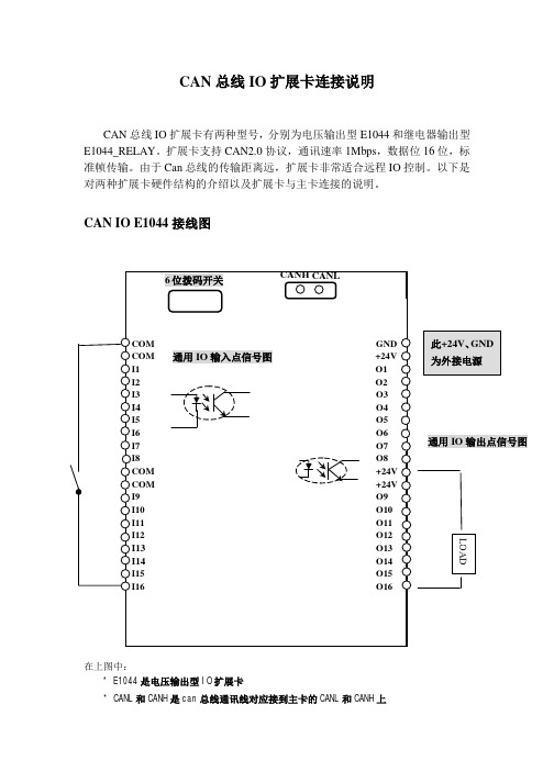
CAN 总线IO 扩展卡连接说明CAN 总线IO 扩展卡有两种型号,分别为电压输出型E1044和继电器输出型E1044_RELAY 。
扩展卡支持CAN2.0协议,通讯速率1Mbps ,数据位16位,标准帧传输。
由于Can 总线的传输距离远,扩展卡非常适合远程IO 控制。
以下是对两种扩展卡硬件结构的介绍以及扩展卡与主卡连接的说明。
CAN IO E1044接线图在上图中:* E1044是电压输出型IO 扩展卡* CANL 和CANH 是can 总线通讯线对应接到主卡的CANL 和CANH 上LOAD通用IO 输出点信号图* 6位拨码开关指示IO 扩展卡硬件地址。
当拨码开关的开关处于ON 位置时,表示0,六位二进制数加一即扩展卡的地址。
如左图,IO 扩展卡地址为9如左图,IO 扩展卡地址为1地址列表如下 拨码开关 扩展卡地址 000000 1 000001 2000010 3000011 4 000100 5 000101 6 000110 7 … … … … … … 111100 61 111101 62 111110 63 11111164* I1-I16是20个通用IO 输入点* O1-O16是16个通用IO 输出点,输出时参考点+24V 对应Ox 的电压约为23.3V ,驱动电流Imax = 500mA 。
ONON输入输出原理图如下:输入点原理图当输入点是 光电开关类型的传感器时,请选用NPN 型。
接线原理图如下:输出点原理图GND外接电源Vin+接人输入点I1~I20CAN IO E1044_RELAY接线图在上图中:* E1044_REALY 是继电器输出型IO 扩展卡。
继电器选用欣大继电器(CLION ,HHC66A-1Z-24VDC ),负载(阻性)最大5A/28VDC, 5A/240VAC 。
* CANL 和CANH 是can 总线通讯线对应接到主卡的CANL 和CANH 上* 6位拨码开关指示IO 扩展卡硬件地址。
控制器CAN总线联网调试说明

CAN2终端电阻设置插针X4:短接后并入120Ω终端电阻;
工作原理:
中继器由主控电路、CAN总线收发电路(两路)、隔离电源等部分组成。两路CAN总线收发电路相互隔离,与主控电路之间信号采用光耦隔离。CAN总线收发电路收到信息后,由主控电路对信息进行处理并转发。
排除电源故障
内部电源电路损坏
返厂维修
中继器无法通信或只能单向通信
CAN总线被短路
查找并排除总线短路点
内部电路损坏
返厂维修
中继器通信不稳定
CAN总线未接终端电阻
在总线两个末端接终端电阻
CAN总线距离过长或节点数目过多
在适当的位置添加总线中继器
3.
3.1.
CAN100F光纤转换器(以下简称转换器)采用DC24V供电,能够将控制器CAN总线联网信息转换后通过光纤进行传输,可将传输距离最大延长到25公里。由于采用光纤作为通信传输介质,具有高隔离电压、防电磁干扰、抗雷击等优点,非常适用于以下两类场合:
联网接口卡型号
适用控制器
LWK100联网接口卡
GST100控制器
LWK200联网接口卡
GST200控制器、GST-QKP04控制器、GST-QKP04/2控制器、GST-QKP01控制器
LWK5000联网接口卡
GST500控制器、GST5000控制器
LWK9000联网接口卡
GST9000控制器
1.3.
DC24V:
DC24V电源无极性输入端子,输入电压应在DC19.2V~28.8V间。
xL、xH:
CAN总线端子。其中主干端子与所在控制器CAN总线连接,或级联下一集中器;分支端子连接该分支CAN总线。单个CAN回路总长度不应超过3000m,节点数目不应超过112个。
第二部分 CAN总线使用说明

Device Net (CAN Open)现场总线一、 现场总线的组成及连接Device Net (CAN Open )现场总线由传感器(节点)、三通接头、电缆线及终端匹配电阻等组成。
现场总线由一根四芯电缆就可将所有传感器均连通并完成所需信息的传输。
连接电缆的方法如下图:注意!(1) 三通接头下端是连接传感器用的。
(2) 电缆线、三通接头及终端匹配电阻连接以后, 应适当固定,尽可能减少电缆线所受的拉力。
三通接头(T 形接头)5~15M 电缆线二、Device Net(CAN Open)总线型传感器1.SK-8J04和SK-9N01组成总线型绞车传感器,SK-9N01是CAN总线绞车隔离栅,其接线端子如下图:2.SK-8B06F和SK-9N02组成总线型泵冲传感器,SK-9N02 CAN总线泵冲隔离栅,其接线端子如下图:3.SK-9N03,各类4~20mA模拟量传感器配上SK-9N03后即组成相应的总线型传感器,SK-9N03是CAN总线,4~20mA模拟量输入隔离栅,其接线端子如下图:三.CAN适配卡CAN适配卡插计算机PCI总线上。
CAN适配卡上有二个CAN口,每个CAN上最多可连接64个节点,总线长度不超过500米,通讯速率设定在125Kbps。
一般使用适配卡上面一个CAN口。
适配卡每个CAN口上均设有125Ω的电阻。
CAN信号通过DB9(针形插座)输出,其引脚定义为:DB9-2 CAN-LDB9-5 CAN ShieldDB7-7 CAN—H四、CAN总线电源使用24V开关电源,开关电源安装在计算机箱内。
24V电源通过YD20K5Z插座(安装在计算机后面板上)向CAN总线供电,其引脚定义为:YD20K5Z —2 +24V—3 0V—5 CAN—L—1 CAN Shield—4 CAN—H五、CAN0V(黑色)+24V(红色)CAN Shield(屏蔽线)现场总线使用说明书上海神开科技工程有限公司- 6 -六、CAN系统接线表1.CAN节点防爆接线盒接线按防爆盒背面铭牌上的标识进行连接。
欧科佳CAN总线系统介绍

CAN总线系统
• CAN总线系统即:采用CAN协议作为总线通讯协议的 总线系统。
• CAN协议是1983年德国博世公司率先提出的,全称 为控制器局域网(CAN-Controller Area Network) 协议。CAN总线是一种多主机方式的串行通讯总线, 与同类产品相比, CAN 总线在数据通信方面具有高 速、实时、可靠和灵活等优点。因此作为一种技术先 进、可靠性高、功能完善、成本合理的网络通讯控制 方式,CAN总线标准被广泛地应用于车载局域网。
万用表量模块输出端的电压是不正确的操作, 应该用好的试灯接在输出端做试验) • 有输出,检查输出端的接线和负载。 • 无输出,检查模块的电源输入端(CN1和CN6 )是否有电源? • 无电源,确保模块的电源接线。否则联系欧科 佳。
故障诊断6
如果TFT彩色屏幕上无对应故障报警。
查看TFT彩色屏幕上是否通讯故障报警? 如果无,则检查是否满足输出条件?(如远光灯
否
足输出要求
是
检查输出端的接线和负 载
检查模块的电源输入(CN1和CN6) 电源输入端是否有电源?
保证接线或更换好的
负载
否
问题是否解决? 是
否
否
对应输出端是否有正常输出?(注 意:直接用万用表量模块输出端的 电压是不正确的操作,应该用好的
试灯接在输出端做试验)
是
检查输出端的接线和负 屏显示画面
仪表MultIC
通过仪表底部的菜单功能按钮可以实现正常显示画面和故障诊断画面之间的相互 切换。按下菜单功能按钮3秒钟可以从正常显示画面切换到故障诊断画面。按下调 节减按钮和调节加按钮可以在不同诊断画面间进行切换。在故障诊断画面时,按 下复位按钮3秒钟,可以对故障累计次数清零。完成故障诊断后,再按下菜单功能 按钮33秒钟可以从故障诊断画面切换回正常显示画面。
CAN IO 模块用户手册说明书
CANIO Module CIOUser manualCIO User ManualUser manual for CAN IO module series CIO v1.00Document version: 1.04Documentation date:January 26th, 2021No part of this document or the software described herein may be reproduced in any form without prior written agreement from EMS Dr. Thomas Wünsche.For technical assistance please contact:EMS Dr. Thomas WünscheSonnenhang 3D-85304 IlmmünsterTel.+49-8441-490260Fax+49-8441-81860Email:************************Our products are continuously improved. Due to this fact specifications may be changed at any time and without announcement.FCC:This device complies with part 15 of the FCCRules. Operation is subject to the following twoconditions:(1) This device may not causeharmful interference, and (2) this device mustaccept any interference received, includinginterference that may cause undesiredoperation.WARNING:CIO hardware and software may not be used inapplications where damage to life, health orprivate property may result from failures in orcaused by these components.Content1 Overview (1)1.1 Attributes (1)1.2 General description (1)1.3 Ordering information (2)2 Configuration (3)2.1 Request and Response (3)2.2 Register (5)2.2.1 Configuration registers (5)2.2.2 TX Mapping registers (6)2.2.3 RX Mapping registers (7)2.2.4 Timer registers (8)2.2.5 Digital IO registers (8)2.2.6 Analog registers (9)2.2.7 Counter registers (9)2.2.8 PWM registers (10)2.2.9 Miscellaneous registers (11)2.3 Reset factory settings (11)2.4 Examples (12)2.4.1 Set baud rate to 250kBaud permanently (12)2.4.2 Request analog value from AD channel 0 (12)2.4.3 Enable Timer 0 in RAM register (12)2.4.4 Inquire Serial Number (12)3 Electrical characteristics (13)3.1 Nominal values (13)3.1.1 General (13)3.1.2 V oltage input (13)3.1.3 Current input (13)3.1.4 Digital output (13)3.2 Limiting values (13)4 Mechanical data (14)4.1 Connection schema CIO-AI8/10V-DI4-DO8 (14)4.2 Dimensions (15)5 Appendix (16)5.1 Instruction for Disposal (16)5.2 FCC Statement (16)5.3 CE Conformity (17)5.4 Revision History (18)THIS PAGE INTENTIONALLY LEFT BLANK1Overview1.1Attributes•CAN I/O module for industrial applications•8 digital outputs 24V•Various input configurations available• 4 or 8 digital inputs 24V• 4 or 8 analog voltage inputs 0-10V or 0-24V• 4 or 8 analog current inputs 0-25mA•Easy integration in CANopen systems•CiA DS 102 and ISO 11898 compatible physical layer•24V or 12V nominal power supply•Galvanic decoupled of CAN transceiver•Extended temperature range•Compact size1.2General descriptionCIO is a versatile I/O module for the CAN bus.Designed for industrial series applications it has a robust and cost efficient layout.CIO supports8digital 24V/500mA output and 8 analog input channels. The analog input channels are available in different combinations of voltage or current inputs. The voltage inputs may be used as digital inputs as well. Four of the eight output channels can be configured for PWM output.CIO is configured by read and write accesses to registers. Configuration can be stored permanently in an EEPROM. While it is in operating mode it can produce CAN messages on events or while being polled. Different modules are addressed by their module ID which is assigned by the user.A module with unknown baud rate or module id can be set in a state where it can berecovered. See chapter 3 for a detailed description.CIO User Manual 1.3Ordering informationNote: xx denotes the language of the delivery:10German20EnglishUser Manual CIO 2Configuration2.1Request and ResponseThe CIO module is configured by requests sent to the module. A request normally addresses a module register by its number. The module answers with a response message. The format of this messages is given below.RequestResponseThe CAN identifiers used for the request and response messages are given by the content of register TX-ID0 (0Fh) and RX-ID0 (30h) plus the module id number. The default content of REQ-ID is 600h, the content of RES-ID is 580h. As the default module id is 1, the module will interact with CAN identifiers 601h and 581h by default.The command byte has the following coding:The module uses the register values in RAM during runtime. While booting the content of the register values in the EEPROM are loaded into the RAM. There are also hard coded factory default settings used for recovery of a misconfigured module. See section 1.2 Reset factory settings for more details.CIO User Manual The error code in the response message has the following meaning:The Data byte count gives the count of significant bytes. Valid values are 0..4.The factory default baud rate is set to 1MBaud.User Manual CIO2.2RegisterThe configuration and runtime functionality of the module is controlled by a series of registers.2.2.1Configuration registersWith this set of registers basic module configuration,like baud rate setting is possible.CIO User Manual The access to the identity register is slightly different. When the module receives a message with TX-ID0 and register number set to 01h, the command byte selects different identity strings, which are returned with the response message.2.2.2TX Mapping registersDuring run time the module can produce or consume messages to perform the functionality as configured by the user. For this purpose a series of registers are implemented.2.2.3RX Mapping registers2.2.4Timer registers2.2.5Digital IO registers2.2.6Analog registers2.2.7Counter registers2.2.8PWM registers2.2.9Miscellaneous registers2.3Reset factory settingsA module with unknown baud rate or module id can be set in a state where it can berecovered. When CAN_H and CAN_L are shortened at start up for more than 3 seconds while the device is supplied with a voltage below the minimum supply voltage range (~5...9V) it boots with CAN initialized to 1MBaud and node id 1. The state is indicated by two LEDs running.In this mode the EEPROM can be completely erased by sending a message with extended (29bit) identifier EE0000h and length 0 to the module. When the module is booted again in normal mode the EEPROM is set to its default values by the firmware of the device.2.4ExamplesFor all examples the Module Id is 1.2.4.1Set baud rate to 250kBaud permanentlyThis write access goes into EEPROM and hence will take effect only after reboot.2.4.2Request analog value from AD channel 0This will return the right alligned raw AD converter value from channel 0.2.4.3Enable Timer 0 in RAM registerAfter enabling Timer 0 the module will produce every 100ms (Default value of register 40h) a message with CAN ID 181h (Default value of register 10h). The Timer 0 reload register (44h) is set by default to 20h, the TX Mapping register 1, which is set to 00848580h. The produced message will therefor contain the values of register 84h, 85h and 80h.2.4.4Inquire Serial NumberThis is a response showing serial number 12345.3Electrical characteristics 3.1Nominal valuesGeneral3.1.13.1.23.1.33.1.43.24Mechanical data4.1Connection schema CIO-AI8/10V-DI4-DO84.2Dimensions5Appendix5.1Instruction for DisposalElectronic Equipment Act (WEEE)EMS is selling its products exclusively to commercial customers. This is the reason why all devices are designed for commercial use and have to be disposed appropriately.In accordance to§10para.2 clause3Electronic Equipment Act (WEEE) the disposal of EMS products is regulated the following way.The equipment must not be disposed at the public collection points. In accordance with the applicable law the disposal has to be done by the customer for own account. The same applies to products, which have been sold to third parties, if those parties do not take care of a disposal in accordance to the applicable law. As an alternative the products can be returned to EMS free of charge.5.2FCC StatementNOTE: This equipment has been tested and found to comply with the limits for a Class A digital device,pursuant to Part15of the FCC rules. These limits are designed to provide reasonable protection against harmful interferences when the equipment is operated in a commercial environment. This equipment generates, uses and can radiate radio frequency energy and,if not installed and used in accordance with the instruction manual, may cause harmful interference to radio communications. Operation of this equipment in a residential area is likely to cause harmful interference in which case the user will be required to correct the interference at his own expense.User Manual CIO 5.3CE ConformityCIO User Manual Revision History5.4User Manual CIO THIS PAGE INTENTIONALLY LEFT BLANK。
2011年宇通客车CAN总线系统培训教材

第一单元 CAN总线技术简介
CAN总线系统的典型布置图
第一单元 CAN总线技术简介
CAN总线系统的典型结构(ACTIA)
MULTIC
ISO 11898 CAN 总线, J1708
视听信号,….
导航系统
视听系统
倒车视频系统
MULTIBUS 内部 CAN 总线系统( ISO 11898) IOU B1 IOU B2 IOU B3 IOU B4
(3)数据共享。具有CAN总线接口的电喷发动机,其他电器可共享(如总线仪表)其 提供的转速、水温、机油压力、机油温度、燃油瞬时供应量等。
(4)硬件方案的软件化实施。 (5)良好的扩充性。 (6)基于计算机技术的总线节点具有强大的故障诊断能力和自我恢复能力。
第一单元 CAN总线技术简介
普通电气结构基本原理
开关4
继电器 灯3
灯4
喇叭
第一单元 CAN总线技术简介
总线控制系统特点
电 源
中
开关1
央
控
制
开关2
单
元
开关3 1
开关4
总线网络
电
灯1
子
控
喇叭
制
单
元
灯3
2
灯4
第一单元 CAN总线技术简介
CAN总线的特点
1. 实时控制 2. 高速:最高可达1Mbits/s (典型应用 250Kbits/s) 3. 强抗干扰能力 4. 配置灵活 5. 成本合理 6. 物理层:带120欧姆终端电阻的双绞线 (典型长度25m)
CAN总线特点
(1)高可靠性。因为CAN总线各个ECU模块之间只用一根或两根线相连传递信息,避 免了各个模块之间反复的连线。连接点少、线少、故障率低。
欧科佳CAN总线控制系统用户手册
资料来源:国内最大的维修资料库 精通维修下载站 :/
资料来源:国内最大的维修资料库 精通维修下载站 :/
资料来源:国内最大的维修资料库 精通维修下载站 :/
资料来源:国内最大的维修资料库 精通维修下载站 :/
资料来源:国内最大的维修资料库 精通维修下载站 :/
资料来源:国内最大的维修资料库 精通维修下载站 :/
资料来源:国内最大的维修资料库 精通维修下载站 :/
资料来源:国内最大的维修资料库 精通维修下载站 :/
资料来源:国内最大的维修资料库 精通维修下载站 :/
资料来源:国内最大的维修资料库 精通维修下载站 :/
资料来源:国内最大的维修资料库 精通维修下载站 :/
资料来源:国内最大的维修资料库 精通维修下载站 :/
资料来源:国内最大的库 精通维修下载站 :/
资料来源:国内最大的维修资料库 精通维修下载站 :/
资料来源:国内最大的维修资料库 精通维修下载站 :/
资料来源:国内最大的维修资料库 精通维修下载站 :/
资料来源:国内最大的维修资料库 精通维修下载站 :/
资料来源:国内最大的维修资料库 精通维修下载站 :/
资料来源:国内最大的维修资料库 精通维修下载站 :/
资料来源:国内最大的维修资料库 精通维修下载站 :/
欧科佳CAN总线系统21页PPT文档

二.CAN 总线---Multibus系统
2.仪表模块MULTIC---功能及布置
1、控制系统的核心单元,分析处理各种信息,发出指令,协调汽车各控制单元及电器设备的工作;
2、TFT彩色液晶显示器,可显示车辆的状态信息及各负载状态同时可作为倒车、乘客门、车内监视器,最多可接 收4路视频信号; 3、6个步进电机驱动数字化指针式仪表;
4、高亮LED符号片和仪表背光;
5、可接收开关控制信号、采集模拟信号和脉冲信号并带少量的小功率输出; 6、与计算机连接进行下载程序和故障诊断。
二.CAN 总线---Multibus系统 3.仪表模块MULTIC---液晶屏
视频画面
二.CAN 总线---Multibus系统 4.仪表模块MULTIC---诊断画面
翻译过来就是控制器局域网简单来说就是在一个区域内存在着若干的计算机芯片为了这些计算机芯片能够互相交换信息而架设的网络
欧科佳CAN总线系统
CAN总线的由来 :
1983年,德国博世公司首先提出了用于汽车的控制器局域 网(CAN-Controller Area Network)协议的构想。到今天CAN 总线已经成为国际上应用最广泛的现场总线并已被采用为 国际标准(ISO11898)。
CN3
CN1:火线、地线; CN2:接仪表CN2提供地址线 CN3:接第二个IOU模块的CN2 CN4:输入(各种传感器、开关) CN5:输出(用电设备)
二.CAN 总线---Multibus系统
7.IOU模块输入输出
IOU—输入输出控制单元
接收开关控制信号 采集模拟信号和脉冲信号 不同输出功率,适合驱动各种设
二. CAN 总线结构
1.CAN总线系统架构原理图
CAN使用手册

CANopen旋转编码器使用说明书内容提要1.注意事项2.标识3.安装4.电气连接5.CANopen 接口6.参数设置7.附件1 注意事项电气安装时应注意以下几个方面:-编码器尽可能地靠近控制单元安装。
-尽可能的使用有屏蔽的双绞线。
-避免信号线靠近高压电缆(例如驱动电缆等)。
-如果需要可以对编码器电源安装EMC 滤波器。
-避免编码器安装在容性性噪声源或开关电源附近。
连接请参考第4 章: "电气连接"。
2 标识设备信息可以通过产品标签上的型号,产品序列号获知。
3 安装。
4 电气连接4.1 CANopen 接线定义连。
4.2 总线终端当编码器为CAN 网络上的最后一个设备时,需要将终端电阻Rt 拨码开关 拨到“ON ”状态。
或感安装时请确保编码器的防护等级符合要求。
避免敲打、撞击、腐蚀编码器4.3 波特率设置:DIP A波特率既可以通过硬件模式设置,也可以通过软件模式设置。
如果DIP A 第4位=OFF 则比特率由对象字典的3000h 来定义,可以通过SDO 报 文进行修改。
如果DIP A 第4 位=ON ,则比特率可由拨码开关 DIP A 进行设置。
由拨码开关设置波特率时,请先关闭掉设备。
波特率可由拨码开关的二进 制状态进行表示(ON 代表1,OFF 代表0)。
拨码开关与波特率对照表例如:设置波特率为250 Kbit/s ,查表可知拨码开关的编码为100,第4位设为ON 。
设置波特率为500 Kbit/s ,查表可知拨码开关的编码为101,第4位设为ON 。
位202122ON/OFF1234位12342012ON FF22/O FF O ONON1234位20122 2ONFFO ONONFF O4.4 节点号设置拨码开关:DIP B编码器的节点号,既可以通过硬件模式设置,也可以由软件模式进行设置,范围 1 至127 之间节点号由数据01h 文进行修改。
如果DIP B 则节点号由DIP B 来定义。
USBCAN-modul8,八通道CAN总线分析仪用户手册
USBCAN-modul 8工业级USB-CAN转换器用户手册文档版本:V5 (2017/06/16)目录1. 功能简介.................................................................................... 错误!未定义书签。
1.1 功能概述 (3)1.2 性能特点 (3)1.3 典型应用 (4)2. 设备安装 (5)2.1 驱动及软件安装 (5)2.2 与PC连接 (5)2.3 CAN总线连接 (5)3. 设备使用 (7)3.1 USB连接 (7)3.2 CAN连接 (7)3.3 CAN总线终端电阻 (8)3.4 系统状态指示灯 (8)4. ECANTools软件使用 (10)4.1 软件启动 (10)4.2 数据收发 (11)4.3 总线分析功能 (12)4.4 中继功能、脱机功能 (13)4.5 其他功能 (14)5. 二次开发 (15)6. 技术规格 (16)7. 常见问题 (17)附录CAN2.0B协议帧格式 (20)1. 功能简介1.1 功能概述USBCAN-modul 8是集成8路CAN接口的高性能型CAN-Bus总线通讯接口卡。
该型号CAN卡可兼容USB2.0总线全速规范,采用USBCAN-modul 8高性能CAN接口卡,PC可以通过USB接口快速连接至CAN-Bus网络,构成现场总线实验室、工业控制、智能小区、汽车电子网络等CAN-Bus网络领域中数据处理、数据采集的CAN-Bus网络控制节点。
USBCAN-modul 8高性能CAN接口卡是CAN-Bus产品开发、CAN-Bus数据分析的强大工具,同时具有体积小巧、即插即用等特点,也是便携式系统用户的最佳选择。
USBCAN-modul 8接口卡上自带USB接口,集成CAN接口电气隔离保护模块,使其避免由于瞬间过流/过压而对设备造成损坏,增强系统在恶劣环境中使用的可靠性。
欧科佳CAN总线系统共21页文档
5、可接收开关控制信号、采集模拟信号和脉冲信号并带少量的小功率输出; 6、与计算机连接进行下载程序和故障诊断。
二.CAN 总线---Multibus系统 3.仪表模块MULTIC---液晶屏
视频画面
二.CAN 总线---Multibus系统 4.仪表模块MULTIC---诊断画面
1. 1939总线网络: 1939总线网络主要负责,总线仪表MultIC与发动机(等带CAN接口的各类
设备)通讯,接收并且处理从设备上传来的各种信息。同时根据这些信息, 在仪表上作出显示。
二. CAN 总线---Multibus系统
Multibus系统常用模块
仪表模块 - MULTIC
输入输出模块 - IOU
二.CAN 总线---Multibus系统 8.CAN总线电器原理图
二.CAN 总线---Multibus系统 9.CAN总线日常维护
谢谢!
谢谢你的阅读
❖ 知识就是财富 ❖ 丰富你的人生
二. CAN 总线结构
1.CAN总线系统架构原理图
底盘1939总线 车身CAN总线
二. CAN 总线结构
2.CAN总线的两个网络
从架构原理图来看, 总线仪表MultIC上总共分出两个网络。 1.纵向的为“车身CAN总线网络”,2.横向的为“底盘1939总线网络”。
车身CAN总线网络 : 车身CAN总线网络主要负责,总线仪表MultIC与输入输出模块IOU通讯,接收 车辆上的开关信号、模拟量信号输入和频率量输入。同时根据这些信号作 为依据,对各个负载供电。
二.CAN 总线---Multibus系统 6.仪表模块MULTIC---接线
CN4
CN3
CN2
- 1、下载文档前请自行甄别文档内容的完整性,平台不提供额外的编辑、内容补充、找答案等附加服务。
- 2、"仅部分预览"的文档,不可在线预览部分如存在完整性等问题,可反馈申请退款(可完整预览的文档不适用该条件!)。
- 3、如文档侵犯您的权益,请联系客服反馈,我们会尽快为您处理(人工客服工作时间:9:00-18:30)。
上海
文件号: 1002340 版本: 1
3
1. 系统结构
CAN总线控制系统应用中主要使用两种控制模块:仪表MultIC和IOU控制模块。 仪表MultIC模块安装在仪表台中,IOU控制模块一般分别安装在车辆前部、顶部或后部。
后部IOU
顶部IOU 仪表MultIC 前部IOU
___________________________________________________________________________________
17 转速表 18 油量表 19 油量过低报警指示 20 水温过高报警指示 21 水温表 22 液晶屏显示信息复位按钮 23 液晶屏对比度按钮 24 液晶屏亮度按钮 25 调节“加”按钮 26 液晶屏菜单功能按钮 27 调节“减”按钮 28 油压表 29 油压过低报警指示 30 电压过低或过高报警指示 31 电压表
欧科佳(上海)汽车电子设备有限公司
上海市松江区九亭镇松江高科技园区九泾路128号5号楼B座 邮编:201615
电话: 021-3763 9808 传真: 021-3763 3360 网址:
欧科佳CAN总线控制系统 用户手册
(非打印页)
版本 1 0
Written
Review
编号 1002340 页数 0 / 21
版本 1
格式A4
上海
文件号: 1002340 版本: 1
1
欧科佳(上海)汽车电子设备有限公司
CAN总线控制系统 用户手册
上海市松江区九亭镇松江高科技园区九泾路128号5号楼B座 邮编:201615
电话: 021-3763 9808 传真: 021-3763 3360 网址:
7
各符号涵义
1
2 3 4567
8
9
10 11 12 13 14 15
16
17
彩色TFT 液 晶显示屏
18 19
20 21
22
23
24
25
26
27
28 29
30 31
1 车速表 2 超速指示 3 左转向指示 4 手刹车指示 5 近光灯指示 6 气压报警指示 7 发动机预热指示 8 轻微故障报警指示 9 远光灯指示 10 重大故障报警指示 11 发动机故障(闪码)灯 12 前雾灯指示 13 后雾灯指示 14 ABS 故障报警指示 15 右转向指示 16 转速过高报警指示
• 4 个半桥 9A 高端/5A 低端输出(216W/120W 持续功率),用于作为半桥或全桥输出,例如控 制一个直流马达旋转;也能设置为高端输出提供一个正电压到负载,或设置为低端输出将负 载接地
• 5 个 PWM(脉宽调制)输出,可以分级控制输出功率,以 10%为一级,从 0%到 100%共十 级,这一功能可用于控制一个直流马达的速度
© 2007 禁止任何未经ACTIA书面同意部分或完全复制使用本文件
上海
文件号: 1002340 版本: 1
9
3.3. 彩色 TFT 液晶显示屏
彩色TFT液晶显示屏在正常状态下可用于显示文字报警信息、符号片、柱状表(通常为气 压)、里程信息以及一些其他特殊内容(视车辆配置而定)。
报警符号指示
气压指示1
9 输入
• 6 个低端开关输入 • 1 个高端开关输入 • 1 个唤醒信号低端开关输入 • 4 个电阻模拟量输入,可用于接燃油量传感器或温度传感器,电阻测量范围从 50Ω到
10KΩ,也能用于作为低端开关输入 • 2 个电压模拟量输入,用于测量电压,测量范围从 0V 到 32V,也能用于作为高端开关输入 • 3 个脉冲信号输入,用于测量发动机转速或车辆速度。脉冲频率范围从 0.5 到 2KHz,也能用
___________________________________________________________________________________
© 2007 禁止任何未经ACTIA书面同意部分或完全复制使用本文件
上海
文件号: 1002340 版本: 1
2
目录
1. 系统结构
3
2. 控制模块技术参数
和熄火以及雨刮器的控制等;
4. 车辆运转信息的实时显示,如水温、油压、电压、油量、气压、车速、发动机系统状 态、ABS系统状态的显示等;
5. 与CAN总线系统相连接的其他设备的工作状态显示; 6. 全车与CAN总线连接的各总成(包括动力总成)以及电气设备发生故障时的实时报警指示
和故障诊断检测信息显示。
气压指示2
文字报警信息
里程信息
常按菜单功能按钮可将屏幕切换至故障诊断画面及一些特殊页面(视车辆配置而定)。 次数:故障的累计次数
接口:接插件编号和相应的端子号
:信号没有输入(输入端) 模块没有输出(输出端)
:信号已输入(输入端) 模块已输出(输出端)
:传感器故障(输入端) 负载故障(输出端)
:车辆上各类灯故障
17
注:此用户手册只是欧科佳公司CAN总线控制系统的通用性说明,具体车辆功能因实际配置不 同可能与本手册相关内容略有差异。
___________________________________________________________________________________
© 2007 禁止任何未经ACTIA书面同意部分或完全复制使用本文件
9 输入
• 24 个低端开关输入(当触点闭合时为接地) • 4 个高端开关输入(当触点闭合时为接电源正极) • 6 个模拟量输入,也能用于作为开关输入 • 2 个脉冲信号输入,用于测量发动机转速或车辆速度。脉冲频率范围从 0.5 到 2KHz,也能用
于作为开关输入 • 2 个系统唤醒信号低端输入 • 2 个系统唤醒信号高端输入
调节加按钮: 此键用于增加仪表背光亮度调节,增加视频对比度调节,增加视频亮度调节和液晶屏 画面翻页。
菜单功能按钮: 按下此键持续3秒钟,可以在液晶屏上切换显示正常显示画面和故障诊断画面
调节减按钮: 此键用于减少仪表背光亮度调节,减少视频对比度调节,减少视频亮度调节和液晶屏 画面翻页
___________________________________________________________________________________
Digitally signed by Jingzhang LIU
Jingzhang LIU DN: CN = Jingzhang LIU, C = CN, O = ACTIA, OU = Engineering Date: 2007.09.19 11:36:46 +08'00'
Digitally signed by Jingzhang LIU
3.1. 组合仪表使用说明 仪表效果图:
___________________________________________________________________________________
© 2007 禁止任何未经ACTIA书面同意部分或完全复制使用本文件
上海
文件号: 1002340 版本: 1
功能键的定义是:
复位按钮: 1) 正常显示画面时,按下此键持续3秒钟,可以归零单次行驶里程表 2) 故障诊断画面时,按下此键持续3秒钟,可以归零电器设备故障记录次数
对比度按钮: 液晶屏显示视频画面时,按下此键进入对比度调节功能,配合“+”键和“-”键可进 行对比度调节。
亮度按钮: 液晶屏显示视频画面时,按下此键进入亮度调节功能,配合“+”键和“-”键可进 行亮度调节。
:车辆上其它设备故障
在这个画面上会显示所有连接到组合仪表的设备的状态,根据各设备的状态提示,可以方便 地进行对车辆设备的检查。
按下调节减按钮和调节加按钮可以在不同诊断画面间进行切换。 在故障诊断画面时,按下复位按钮3秒钟,可以对故障累计次数清零。 常按菜单功能按钮可将屏幕切换回正常页面 。
___________________________________________________________________________________
Aprov.
制作者
日期
版本记录
说明
2007.9 2007.4
附录更新 首次发行
Hanmo
Hu Digitally signed by Hanmo Hu DN: cn=Hanmo Hu, c=CN, o=ACTIA CHINA, ou=ACTIA Group, email=hanmo.hu@actia. Date: 2007.09.19 09:40:49 +08'00'
上海
文件号: 1002340 版本: 1
6
3. 系统功能和使用说明
在客车应用中,欧科佳CAN总线控制系统主要实现了以下功能: 1. 底盘动力总成各部分之间通过J1939协议的总线式连接; 2. 全车信号的总线式采集和处理; 3. 车身和底盘电气负载的控制,如前部组合灯组的控制、后部组合灯组、发动机的起动
4
2.1. 仪表MULTIC模块
4
2.2. IOU控制模块
5
3. 系统功能和使用说明
6
3.1. 组合仪表使用说明
6
3.2. 功能键
8
3.3. 彩色TFT液晶显示屏
94. Biblioteka 科佳CAN总线控制系统故障诊断10
5. 模块接插件定义
11
6. 对模块可能造成损坏的错误操作
16
7. IOU模块安装规则
17
8. 附录
于作为开关输入
9 输出
• 2 个 9A 高端开关输出(216W 持续功率),提供一个正电压到负载,可输出峰值电流 35A (840W),持续时间为 1 秒
