蒸发式空冷器使用说明书
科叶蒸发式冷风机说明书
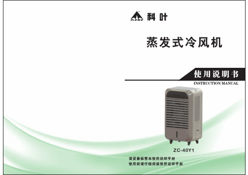
尊敬的科叶用户:科叶产品质量优,性能佳。
为了方便您使用,请仔细阅读说明书,并按照说明书的步骤操作。
自始至终,科叶一流的服务将伴随着您,使用时无论有什么问题,请按照说明书背面的电话、地址联系,我们时刻恭候为你服务。
科叶-诚信经营,真诚到永远。
由于产品的改进,您所购买的科叶冷风机可能与说明书中的介绍不完全一致,谨此致歉!故障现象一、无法开关机1、电源没接通2、控制器故障1、检查电源插头2、更换控制器可能原因解决方法二、频繁烧保险丝1、潜水泵损坏1、更换潜水泵三、漏水1、本机放置不平2、水箱漏水3、排水盖母未拧紧1、将本机移到平的位置2、修补水箱3、拧紧排水盖母四、噪音过大1、风叶脏污、变形或损坏2、电机磨损3、有杂物挡住进出风口位置1、清洗或更换风叶2、更换电机3、清除障碍物五、无送风或风速过小1、湿帘或防尘网堵塞2、风机不转或转速过慢1、清洗或更换湿帘和防尘网2、检查电机是否损坏六、不制冷1、水箱缺水(水箱水位低于L位线)2、水位控制系统故障3、潜水泵损坏4、控制器故障1、往水箱加水,直至最高位的H水位线2、检修水位传感器3、更换潜水泵4、更换控制器七、水箱内和过滤网上有白色沉淀1、供水的矿物质含量高1、增加清洗频率备注:如有更新,不作另行安排。
产品介绍P3适用范围P4使用环境P4编号说明P4注意事项P5结构简图P7技术参数P9电路原理简图P9控制面板P10操作说明P10遥控器的使用P11产品保养P11故障及解决方法P13保修卡P14环保节能冷风机具有以下优点:节能:比一般传统空调,节省能源高达80%以上。
环保:环保节能冷风机在运行时,绝不向外界排出有害物质(氟利昂)。
高效:用最小的能源造最大的制冷净化效果。
环保节能冷风机,是结合我国的气候条件而开发的新一代产品,适合我国大部分地区使用。
其工作原理是新风使水份极速气化,大量吸热从而达到降温的效果。
工作时,水泵抽取水箱内的水,通过分水器均匀分布到用特殊纤维制造的蒸发换热器上,而大流量轴流风机的转动使室外新鲜空气以高速度穿过蒸发换热器,在把水气化的同时,产生大量的氧离子,富氧新风经加压后送入室内,并通过敞开的门窗把混浊的空气排出,从而完成换气降温全过程。
蒸发移动式环保空调操作规程

蒸发移动式环保空调操作规程第一章概述1.1 目的蒸发移动式环保空调是一种新型的空调设备,具有节能环保、移动灵活等特点。
为了确保空调设备的正常运行和用户的安全使用,制定本操作规程。
1.2 适用范围本操作规程适用于所有使用蒸发移动式环保空调的用户。
第二章操作准备2.1 设备检查在使用蒸发移动式环保空调之前,用户应仔细检查设备是否完好无损,主要包括外壳、电源线、滤网等部分。
2.2 电源接入将空调设备的电源线插入符合国家标准的插座,并确保电源线没有损坏。
2.3 水箱填充打开空调设备的水箱盖,将清洁的自来水或蒸馏水倒入水箱中,注意不要超过水位线。
第三章操作步骤3.1 打开空调设备将空调设备的开关调至“开启”位置,此时空调设备即开始工作。
3.2 调节温度通过空调设备上的温度控制按钮,可以调节空调设备的出风温度,根据室内的实际需求进行调整。
3.3 调节风速通过空调设备上的风速控制按钮,可以调节空调设备的风速,可选择低、中、高三档风速。
3.4 调节湿度蒸发移动式环保空调具有调节湿度的功能,在使用过程中,可以根据需要选择适宜的湿度档位。
3.5 定时功能空调设备配有定时功能,用户可以根据需要设置定时开关机时间,在规定的时间内自动开启或关闭空调设备。
3.6 安全使用在使用空调设备时,应注意以下事项:- 避免将空调设备暴露在阳光直射的地方,以免影响散热效果。
- 避免在潮湿的地方使用空调设备,以免发生漏电等安全问题。
- 避免将空调设备放置在易燃物附近,以免引发火灾。
- 避免将空调设备放置在儿童易触及的地方,以免发生意外伤害。
第四章维护与保养4.1 滤网清洁定期清洗空调设备的滤网,可使用软刷或水龙头冲洗,确保滤网的通风性能良好。
4.2 水箱清洁定期清洗空调设备的水箱,可使用中性洗涤剂和清水进行清洁,避免水箱内滋生细菌。
4.3 故障排除如果发现空调设备出现异常情况,如无法正常开启、异常噪音等,应立即停止使用,并联系售后服务人员进行维修。
澳蓝 AZL07-ZC13A 蒸发式冷气机 说明书

使 用 说 明 书AZL07-ZC13A制造商:澳蓝(福建)实业有限公司地址:福建省福州市仓山区盖山镇官洲路12号TEL:*************、87609922、88060016、88060086FAX:*************郑重声名:专利产品、仿冒必究国家知识产权局专利号: ZL03357388.3目 录重要提示 (2)产品介绍............................................................................................................2适用场所............................................................................................................2编号说明............................................................................................................3冷气机结构图解..........................................................................................3电控使用操作说明......................................................................................................4电路接线图............................................................................................................5侧板拆装示意图............................................................................................................6运行、保养与维护.........................................................................................................6技术参数...............................................................................................................7故障及排除方法 (7)前 言感谢您选择澳蓝蒸发式冷气机。
Daikin A210758 冷却系统蒸发器手册说明书

Product DataA210758 Fig. 1 – Typical Coil This evaporator coil incorporates proven standards for reliable system operation and performance throughout the life of this product. These quality coils, manufactured and installed as part of a total comfort system, provide AHRI-rated performance ratings and are additionally listed with UL and c-UL.Available for use in Puron® R-410A refrigerant only, it is a cased V-coil or slope coil that is housed in a durable, 24-gauge, pre-painted taupe metallic cabinet. The fully insulated cabinet (foil faced with R-2.1 insulation) provides for quiet efficient operation of the evaporator coil.DESIGN FEATURES Performance— Designed with performance in mind, this new evaporator coil offers lower pressure drops to enhance system performance and airflow characteristics.Thermostatic Expansion Valves (TXV)— All coils have refrigerant-specific, factory-installed TXVs. All models are factory pre-set to approximately 10° of superheat at the suction service valve. Durable Condensate Pan — The corrosion-resistant drain pan is designed of a “Polybutylene terephthalate” material (PBT) that offers unsurpassed pan strength. It is engineered with proper slope to help ensure water drainage, improved moisture removal, and home comfort. Condensate Drain Pan Plugs — The drain pan is supplied with three water-tight drain plugs to prevent leakage from unused drain connections.Refrigerant Connections— Provided with industry proven sweat connections for leak-free operation to maintain system reliability. The location of the lineset connections allows for removal of the access door for easy cleaning/servicing of the coils, as well as easy access to the TXV. All models come from the factory with enough length of straight tube—once tubing is cut—to accommodate braze-less compression fittings.Burst Pressure — Meets or exceeds burst pressure of 1900 psi, which is at least three times the maximum operating pressure it would see in actual cooling-only application.UV Knockout— This cased coil comes with factory-installed UV knockouts for quick and easy installation of UV light. Serviceability — Comes with a “no delta plate” for easy, quick access to both sides of the coil for service and cleaning. Also, after the door is removed and refrigerant lines disconnected, the coil is removable from the front of the unit without the use of any tools.CVPVA, CSPVAEvaporator Coil with Vertex™Technology Upflow/DownflowAC OnlyCVPVA, CSPVA: Product DataMODEL NUMBER NOMENCLATUREA200449123456789101112CVPVA3617XMCProduct Variations C = CoilC = Cooling onlyTypeTubing Design M= MicrochannelV = V-Coil S = Slope CoilRefrigerant TypeP = Puron® Refrigerant (R-410A) TXVMetering Device X = TXVCoil Configuration Cabinet Width (Nom.)14 = 14-in (356 mm)17 = 17-in (432 mm)21 = 21-in (533 mm)24 = 24-in (610 mm)V = Upflow/Downflow M = Multi-poiseCabinet Finish A = Major SeriesUnit Capacity (Nom.)18 - 23 = 1½ Ton 24 - 29 = 2 T on 30 - 35 = 2½ Ton 36 - 41 = 3 T on 42 - 47 = 3½ Ton 48 - 51 = 4 T on 60 - 62 = 5 T onTable 1 – AccessoriesPart Number DescriptionKGADA0101ALL Coil Adapter Kits - No Offset KGADA0201ALL Coil Adapter Kits - Single Offset KGADA0301ALLCoil Adapter Kits - Double OffsetUse of the AHRI CertifiedTM Mark indicates a manufacturer’s participation in the program.For verification of certification for individualproducts, go to .Table 2 – COOLING CAPACITIES (MBH) - PURON® REFRIGERANT (R-410A)INDOOR COILAIRSATURATED TEMPERATURE LEAVING EVAPORATOR °F (°C)35 (2)40 (4)45 (7)50 (10)55 (13)CFM EWB TC SHC BF TC SHC BF TC SHC BF TC SHC BF TC SHC BF6007241.5520.220.0037.6818.180.0032.9615.980.0027.7113.700.3321.8111.380.23 6734.1720.840.0029.8218.630.2325.2116.430.2120.0114.050.2014.4211.570.22 6227.0421.220.1922.9518.980.1918.3516.620.2014.4814.480.2011.9311.930.338007250.5324.520.0046.1322.140.0040.4219.520.0034.0216.790.3827.1514.100.29 6741.8025.470.0036.5922.890.2830.9820.230.2624.6817.410.2517.8914.480.25 6233.2426.200.2428.3923.560.2422.6120.680.2418.2618.260.2415.2015.200.3610007258.6328.230.0053.3425.480.0046.7922.550.0039.4719.480.4131.2616.330.32 6748.3729.490.0042.3926.560.3235.9423.540.3028.6720.330.2920.6416.870.30 6238.4630.450.2832.7127.420.2826.1624.170.2821.6121.610.2718.1218.120.39INDOOR COILAIRSATURATED TEMPERATURE LEAVING EVAPORATOR °F (°C)35 (2)40 (4)45 (7)50 (10)55 (13)CFM EWB TC SHC BF TC SHC BF TC SHC BF TC SHC BF TC SHC BF4507232.5915.820.0029.5014.190.0025.8212.450.0021.6810.630.2316.998.780.15 6726.7116.170.2523.3414.420.1519.6912.670.1315.6110.770.1311.298.860.15 6221.0616.300.1117.9414.590.1214.3812.760.1210.8910.890.148.958.950.296007240.2519.820.0037.0017.710.0032.4315.590.0027.3313.390.2821.5511.120.19 6733.5520.270.0029.3718.140.1924.7915.970.1719.7413.680.1614.3711.350.17 6226.6220.640.1522.6218.470.1518.1216.180.1614.1114.110.1611.5711.570.317507247.3823.000.0043.5920.800.0038.2818.350.0032.3115.810.3225.5613.190.23 6739.5323.870.0034.6621.430.2329.3318.940.2023.4616.310.2017.0213.530.21 6231.4424.460.1926.9022.020.1921.4919.330.1917.0917.090.1914.1914.190.32INDOOR COILAIRSATURATED TEMPERATURE LEAVING EVAPORATOR °F (°C)35 (2)40 (4)45 (7)50 (10)55 (13)CFM EWB TC SHC BF TC SHC BF TC SHC BF TC SHC BF TC SHC BF6007243.0321.170.0039.0819.050.0034.2816.780.0028.9814.460.2922.8512.010.19 6735.4221.800.0031.0419.540.1926.2517.240.1720.9214.780.1615.2312.270.17 6228.1322.240.1524.0219.960.1519.2017.500.1614.9514.950.1612.3312.330.308007252.3525.800.0048.1723.370.0042.3220.640.0035.8317.860.3428.6414.990.25 6743.7126.900.0038.2924.130.2532.5121.410.2126.0118.470.2118.9615.420.21 6234.7627.610.2029.7524.880.2023.8121.900.2019.0719.070.2015.9515.950.3210007261.1529.780.0056.0427.070.0049.3024.000.0041.7420.790.3733.4517.540.28 6750.7831.280.0044.5428.130.2937.8925.040.2630.3721.690.2422.1818.200.24 6240.4832.320.2434.6729.190.2427.7525.780.2322.7322.730.2319.1319.130.35INDOOR COILAIRSATURATED TEMPERATURE LEAVING EVAPORATOR °F (°C)35 (2)40 (4)45 (7)50 (10)55 (13)CFM EWB TC SHC BF TC SHC BF TC SHC BF TC SHC BF TC SHC BF7507250.6025.110.0046.0522.680.0040.4220.030.0034.1017.240.3226.9814.400.23 6741.7426.060.0036.5923.390.2330.9620.670.2024.7717.810.2018.0314.820.20 6233.2026.710.1928.4124.050.1922.6921.100.1918.0318.030.1915.0014.990.3210007260.9730.180.0056.0027.450.0049.2624.340.0041.6721.070.3633.0317.670.28 6750.7831.710.0044.5928.580.2837.8925.400.2530.3321.970.2422.1718.430.25 6240.4632.750.2434.7029.590.2427.7926.150.2322.6622.660.2319.0119.010.3512507270.4934.540.0064.4231.430.0056.7127.980.0048.0824.330.3938.2020.480.32 6758.3336.500.3951.3333.010.3243.7429.450.3035.0725.580.2925.5021.440.29 6246.6638.020.2840.0534.460.2832.0830.530.2726.7126.710.2822.5022.500.39CFM EWB TC SHC BF TC SHC BF TC SHC BF TC SHC BF TC SHC BF9007259.6829.490.0054.3826.720.0047.7323.630.0040.2620.380.3432.1817.140.26 6749.2830.780.3943.1927.680.2636.6324.520.2429.3121.170.2321.3617.670.23 6239.2531.700.2233.6328.610.2226.9025.190.2221.6721.670.2218.1518.150.3412007271.2535.040.0065.3731.960.0057.5628.420.0048.6324.620.3838.5920.710.31 6759.2137.050.3952.1233.530.3144.3529.840.2935.4725.850.2825.8321.670.28 6247.2838.500.2740.3934.840.2732.5430.890.2726.9526.950.2722.6822.680.3815007281.6939.890.0074.7236.390.0065.8732.500.0055.8128.310.4144.2323.860.35 6767.6642.480.4059.6638.550.3550.9134.470.3340.7229.950.3229.7525.280.32 6254.2044.520.3146.6640.490.3137.3335.930.3131.5131.510.3126.6326.630.42INDOOR COILAIRSATURATED TEMPERATURE LEAVING EVAPORATOR °F (°C)35 (2)40 (4)45 (7)50 (10)55 (13)CFM EWB TC SHC BF TC SHC BF TC SHC BF TC SHC BF TC SHC BF9007261.3029.570.0055.5926.760.0048.9123.690.0041.4320.520.3233.2017.270.24 6750.3530.800.3444.1827.680.2337.5824.620.2030.1521.300.2022.0617.840.20 6240.1131.700.1934.2228.550.1927.6125.270.1922.1722.170.1918.5618.560.3212007272.8235.080.0067.0132.100.0059.1828.620.0050.2324.890.3640.3921.090.28 6760.7037.230.3453.5033.670.2845.5930.040.2636.6726.140.2426.9222.050.24 6248.5138.690.2441.7435.130.2433.5731.170.2327.7227.720.2423.4123.410.3515007282.4139.520.0076.4236.500.0067.6832.720.0057.6028.600.3945.9624.230.32 6769.1942.580.3661.1838.790.3152.3634.740.3042.1230.330.2930.9225.680.28 6255.4544.650.2847.5940.690.2738.5536.320.2732.5032.500.2827.6227.620.39INDOOR COILAIRSATURATED TEMPERATURE LEAVING EVAPORATOR °F (°C)35 (2)40 (4)45 (7)50 (10)55 (13)CFM EWB TC SHC BF TC SHC BF TC SHC BF TC SHC BF TC SHC BF12007277.2537.430.0070.2234.000.0062.0030.340.0052.7326.420.3642.0222.290.28 6763.5139.400.3556.0835.700.2847.8231.870.2638.4627.740.2428.3023.470.24 6250.7940.970.2443.7337.230.2435.1933.080.2329.0729.070.2324.5424.540.3516007290.7143.750.0083.0540.080.0073.5135.940.0062.7731.550.4050.6726.890.34 6775.1846.840.3866.4842.590.3456.9638.320.3145.9633.600.2933.7028.440.29 6260.3249.310.2952.0745.000.2941.9740.220.2835.6435.640.2930.2830.280.40200072100.7048.580.0093.6545.160.0083.1440.730.0071.1535.920.4257.6130.800.37 6784.7853.190.4075.2348.640.3764.6043.920.3552.1038.630.3338.1832.830.33 6268.1056.450.3358.6451.800.3247.5346.470.3241.8641.860.3335.3435.340.43INDOOR COILAIRSATURATED TEMPERATURE LEAVING EVAPORATOR °F (°C)35 (2)40 (4)45 (7)50 (10)55 (13)CFM EWB TC SHC BF TC SHC BF TC SHC BF TC SHC BF TC SHC BF12007282.2939.970.0075.0636.490.0066.5632.660.0056.8128.530.3245.5124.170.24 6767.8842.240.2960.1238.370.2451.4034.330.2241.5230.010.2030.7425.470.20 6254.4244.060.2046.6839.990.1937.9135.680.1931.3731.370.2026.4726.470.3216007296.9146.860.0088.9143.080.0079.1338.860.0067.8634.230.3554.5929.210.29 6780.4650.390.3271.5446.070.2961.4641.520.2749.7836.520.2536.9231.200.25 6264.6753.150.2556.0548.730.2545.4443.710.2439.0639.060.2532.9432.940.36200072108.8652.410.0099.9948.450.0089.1543.890.0076.7438.920.3861.7533.390.32 6790.4057.050.3580.5852.390.3369.5247.550.3156.5142.110.2941.8836.090.29 6272.9360.890.2963.0256.060.2851.6150.670.2845.5245.520.3038.5638.560.40©2022 Carrier Corp.• All rights reserved.Edition Date: 03/22Catalog No: CVPV A-01PDReplaces: NewSee notes below.COOLING CAPACITIES NOTES:1.Contact manufacturer for cooling capacities at conditions other than shown in table.2.Formulas:Leaving db = entering db - sensible heat cap.1.09 x CFMLeaving wb = wb corresponding to enthalpy of air leaving coil (h LWB )h LWB = h EWB - total capacity (Btuh)4.5 x CFMWhere h EWB = enthalpy of air entering coil3.SHC is based on 80︒F db temperature of air entering the evaporator coil.Below 80︒F db, subtract (Correction Factor x CFM) from SHC.Above 80︒F db, add (Correction Factor x CFM) to SHC.4.Direct interpolation is permissible. Do not extrapolate.5.Fan motor heat has not been deducted.6.All data points are based on approximately 10︒F superheat measured at the suction service valve and use of thermostatic expansion valve (TXV)device.7.All units have sweat suction-tube connection and a liquid-tube connection. For 1-1/8-in. system suction tube, 3/4 x 1-1/8-in. suction tubeconnection adapter is available as accessory.8.Before using maximum cfm shown in table, check coil static pressure drop to ensure system blower can provide necessary static pressure neededfor coil and duct systems.9.Bypass Factor = 0 indicates no psychometric solution. Use bypass factor of next lower EWB for approximation.Interpolation is permissible.Correction Factor = 1.09 x (1 - BF) x (db - 80)CFMEWB TC SHC BF TC SHC BF TC SHC BF TC SHC BF TC SHC BF 15007294.0844.910.0086.4641.470.0077.2037.490.0066.5433.160.2953.8728.400.236778.0948.350.2569.7744.380.2360.1340.090.2048.9235.410.1936.5330.360.186262.9951.170.1954.5246.950.1844.6242.280.1838.0238.020.2032.1832.180.32200072109.1452.030.00100.7148.380.0090.3444.120.0078.2439.370.3263.7034.050.276791.1057.170.2981.6752.820.2770.7848.100.2557.8742.870.2443.4237.070.236273.6861.300.2464.0456.710.2353.7752.670.2146.9546.950.2539.8039.800.36250072120.5857.580.00111.6453.880.00100.4349.420.4187.3244.410.3571.3938.730.3167100.9564.340.3290.7959.730.3078.9854.760.2964.8149.150.2748.8942.830.276281.9469.820.2871.3964.990.2760.8260.820.2354.6554.640.3046.3846.380.40CFM - Cubic Ft. per MinuteEWB - Entering Wet Bulb (_F)LWB - Leaving Wet Bulb (_F)TC - Gross Cooling Capacity 1000 BtuhSHC - Gross Sensible Capacity 1000 BtuhBF - Bypass FactorMBH - 1000 BtuhBYPASS FACTORENTERING AIR DRY BULB TEMPERATURE (︒F)79 78 77 76 75 Under 75 8182838484Above 85Correction Factor0.10 0.20 0.300.98 0.87 0.76 1.96 1.74 1.53 2.94 2.62 2.29 3.92 3.49 3.05 4.914.363.82Use formula shown below。
蒸发式冷风机使用说明
蒸发式冷风机使用说明蒸发式冷风机使用说明蒸发式冷风机是一种新型的空气调节设备,它可以通过水的蒸发来降低空气温度,同时还能够净化空气。
下面就为大家详细介绍一下蒸发式冷风机的使用说明。
一、产品介绍1.产品概述:蒸发式冷风机是一种采用环保材料制造的小型空气调节设备,它通过水的蒸发来降低空气温度,同时还能够净化空气。
2.产品特点:蒸发式冷风机具有体积小、噪音低、节能环保等特点,适合于家庭、办公室、商店等小型场所使用。
3.产品结构:蒸发式冷风机主要由水箱、水泵、风扇、过滤器等部件组成。
二、使用方法1.准备工作:将蒸发式冷风机放置在通风良好的地方,并将其插入电源插座。
2.加水操作:打开水箱盖子,在水箱中加入适量清洁干净的自来水或矿泉水,注满后盖上盖子。
3.启动操作:将电源插头插入插座,按下开关键,蒸发式冷风机即可开始工作。
4.调节温度:蒸发式冷风机的温度调节一般有三档,可以根据需要选择不同的档位。
通常情况下,第一档为自然风,第二档为低速制冷,第三档为高速制冷。
5.清洁维护:使用一段时间后,需要对蒸发式冷风机进行清洁维护。
首先要切断电源,并将水箱中的水倒掉。
然后用清水或者中性洗涤剂清洗过滤器、水箱等部件,并擦干后再重新组装。
三、注意事项1.使用前请先仔细阅读产品说明书,并按照说明书正确操作。
2.在加水时,请勿超过最高水位线。
3.使用过程中请勿将手伸入蒸发式冷风机内部或触碰其运转部件。
4.在清洁维护时,请务必切断电源并等待设备完全停止运转后再进行操作。
5.请勿在潮湿环境下长时间使用蒸发式冷风机,以免影响其正常使用寿命。
四、常见问题解答1.蒸发式冷风机为什么不能制冷?答:可能是因为水箱中的水不足或者过滤器被堵塞了。
可以检查一下水箱和过滤器,如果发现问题可以及时清洗和更换。
2.蒸发式冷风机使用一段时间后会出现异味,怎么办?答:可能是因为过滤器没有及时清洗,导致细菌滋生。
可以将过滤器取出来用清水或中性洗涤剂清洗干净后再重新组装。
Maxx Air EC18DVS 蒸发式冷气器说明书
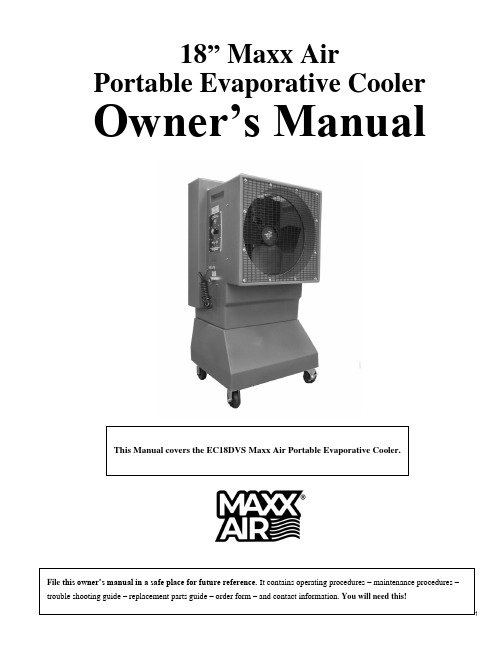
18” Maxx AirPortable Evaporative Cooler Owner’s ManualThis Manual covers the EC18DVS Maxx Air Portable Evaporative Cooler.File this owner’s manual in a safe place for future reference. It contains operating procedures – maintenance procedures –trouble shooting guide – replacement parts guide – order form – and contact information. You will need this!Warnings and CautionsRead before operating Maxx Air Portable Evaporative Cooler ELECTRICALWARNING Do not use a 3 prong to 2 prong adapter on the electrical power cord. Use 14 gauge extension cord only.WARNING Do not remove the grounding lug from the electrical power cord plug.Use only 3 prong, grounded receptacles.WARNING Disconnect the Maxx Air Portable Evaporative Cooler from your electrical power source before performing any service action.WARNING Your Maxx Air unit must be plugged into a fused or circuit breaker protected 20 Amp, 120 Volt, 60 Hz circuit –unless specifically manufactured for another voltage / frequency configuration. See manufacturer’s label oncooler. A ground fault circuit interrupter protected circuit is strongly recommended.WARNING Check your units electric power cord for insulation breaks, cracks or fraying. If any of these conditions are found DO NOT USE. See your distributor for immediate service replacement parts.WARNING Some electric motors require periodic oiling. Check your model for oil fill holes. A couple drops of light oil per year normally will be sufficient. Heavy usage may require additional oil.WARNING To reduce the risk of fire or electrical shock, DO NOT USE with any solid-state speed control device. WARNING To reduce the risk of electrical shock or injury to persons, DO NOT USE cooler in a window.WATERWARNING Do not connect your Maxx Air Portable Evaporative Cooler to any water source where water pressure exceeds60 p.s.i. If your water source is above 60 p.s.i. you must use a pressure regulator (which can be foundat your local hardware store).WARNING ALWAYS TURN-OFF WATER AT THE SOURCE EVERY NIGHT.Table of Contents1.0 Introduction1.1 Quick Start1.2 Operate unit for 2 weeks before adding Evap-O-Matic Tablets2.0 How Evaporative Cooling Works3.0 Unpacking your new Maxx Air unit4.0 Set-up your Maxx Air unit4.1 Connecting the electrical supply4.2 Connecting the water supply5.0 Operating procedures5.1 Filling the units reservoir with water5.2 Turn-on pump5.3 Turn-on Fan6.0 Daily Operating procedures6.1 Turn-on pump6.2 Turn-on fan6.3 Turn-off unit7.0 Maintenance7.1 Access inside of unit7.2 Removing the cooling media7.3 Daily maintenance7.4 Periodic maintenance7.5 Maxx Air Trouble Shooting Guide8.0 Storage9.0 Wiring Diagrams for 18” unit10.0 WarrantyFile this owner’s manual in a safe place for future ref erence. It contains operating procedures – maintenance procedures –trouble shooting guide – replacement parts guide – order form – and contact information. You will need this!1.0Introduction•Your Maxx Air was tested 3 ways. Your unit was tested for 1. Maximum air flow at operating static pressure.Only Maxx Air is tested in operating conditions with 2. Water and 3. Electricity before it is shipped.•Maxx Air is easy to operate– needs only tap water and electricity to operate.•Maxx Air is easy to move– roll your Maxx Air to the area you want to cool. Maxx Air comes standard with straight and swivel / lock casters which make moving your Maxx Air a breeze.1.1 Quick Start– Your Quick Start Information is located inside theinformation packet shipped with your unit.Look on the front of your Maxx Air packaging in a plastic sleeve.1.2 Evap-O-Matic Tablet – Chemical Water Treatment. Operate your unitfor 2 weeks – then, flush out old water – add clean water – then add ½Chemical Water Treatment tablet. Note: Tablet makes water foam whichcan cause unit to spray water temporarily (for a day or two). You canorder more tablets by calling 1.800.433.1626.2.0 How Evaporative Cooling WorksKeeping in mind that regular fans only circulate same temperature air -same humidity –your Maxx Air portable evaporative cooler takes thatsame existing air, combines it with evaporating water (which dramatically lowers the temperature) immediately relieving hot, dry areas, similar to the conditions when a natural rain storm approaches, the temperature drops noticeably cooler, because the air is saturated with water. Because your air is now saturated with water it becomes noticeably cooler. In high humidity areas the temperature will not be as cool –however, the Maxx Air was engineered efficient to evaporate perspiration and sweat from employees to keep them cooler.3.0 Unpacking your new Maxx Air unitNote: Carefully examine your Maxx Air shipping carton for damagebefore opening. If your carton is damaged – notify the shipper immediately!Your EC18” unit was shi pped strapped a wooden pallet inside a cardboard box.First remove the straps then you may open the cardboard box. Your Maxx Aircomes with a box of casters. Attach swivel casters to fan side of unit and straightcasters to pad side. Use a 3/8” wrench to attach casters.4.0 Set-up your Maxx Air unit.Roll your Maxx Air unit to a level surface and lock the swivel casters to prevent accidental movement. Electrical cord for 120V, 15Amp connection. Note: Standard ¾” water connection for utility water source under 60 p.s.i.How the Maxx Air portableevaporative cooler works4.1 Connecting the electrical supplyAll Maxx Air models require regular 3 prongs, ground with 120 volt power supply. Plug electrical cord into receptacle. If using an extension cord be sure it is rated for at least 20 amps for the distance your cord is running. To be safe – make sure no other equipment, such as a radio or electrical equipment, is plugged into the same circuit. The Maxx Air should run smoothly on 20 amp, 120 volt, and 60 Hz circuit.4.2 Connecting the water supplyConnect standard water hose to female fitting on the right side of your Maxx Air (looking at the fan blade side). If your water pressure is above 60 pounds per square inch (p.s.i.) you must use a pressure regulator (which can be found at your local hardware store). Note: Do not connect to water source exceeding 60 p.s.i. – this can cause damage to your Maxx Air.5.0 Operating proceduresBack your Maxx Air unit up to a fresh air source such as an open door or window so the unit can pull in fresh air from the outside. Next, make sure you have a natural exhaust at the opposite end of the room, bay or building such as a window, door or bay door. This will ensure maximum efficiency from your unit. Finally make sure there are no obstructions between your Maxx Air and the people / area you need to cool.5.1 Filling the units reservoir with waterOnce your water hose is connected, turn water on and fill the reservoir with water. Listen carefully. You can hearwater filling the reservoir. Check your water connection – make sure there is no dripping. Once the reservoir is filled with water the float valve will automatically shut off the water source. When you no longer hear the water running – you know that the float valve is fully operational (the water turns off automatically) and you are now ready to turn on the water pump. Warning! Do not run water pump without water in the reservoir.5.2 Turn-on pumpTo turn-on the water pump - flip the toggle switch for the water pump to on. Switch is located on front side of unit. Warning! Do not run water pump without water in the reservoir . The water pump will now begin pumping water to the top of the unit so that gravity will allow the water to run down the backside of unit inside and on the cooling pads. Once your Maxx Air cooling pads are saturated – then, you are ready to turn fan on high and begin to feel the cooling effect from your new Maxx Air. Note: After your cooling pads are broken in (typically takes 1 -2 weeks in operation) it will take less time to saturate pads for start-up. This is a good time to dump the old water – add ½ Evap-O-Matic Chemical Water Treatment tablet and refill with fresh water. (Simply remove a cooling pad to place tablet inside of water reservoir).NOTE: EXTENDED COOLING ZONE: 40’ TO 50’ FROM MAXX AIR UNIT. AIR MOVEMENT INCLUDES WARM AIR MIXING WITH COOLEDAIR.5.4 Turn-on FanOnce your cooling pads are saturated with water – you may turn your Maxx Air unit on high. Now you can begin to feel the Maxx Air difference in temperature. After your Maxx Air has run for 5 minutes or so, visually inspect the pads – if water is dripping outside the unit – gently adjust pads at the bottom to stop water flowing outside the unit.6.0 Daily Operating procedures6.1 Turn-on water pumpTurn on water pump to unit – turn fan on low – let cooling pads get saturated – then turn fan on high for cooling.You must determine what works best for you and your specific environment.6.2 Turn fan on highWhen you can see that the cooling pads are saturated with water – turn the fan on high and feel the cooler air coming from your Maxx Air unit. Adjust the fan speed for your comfort.6.3 Turn-off unit at end of day15 minutes before closing for the day – (1.) Turn off water pump with toggle switch – (2.) Leave fan running – this action will shut-off water to the cooling pads while keeping the fan running. The fan will dry out the cooling pads. (3.) When the cooling pads are thoroughly dry – turn off fan. Drying your cooling pads thoroughly - everyday will help prevent mold and mildew growth, plus it will prolong the life of your cooling pads.7.0 Maintenance7.1 Access inside of unitTurn-off water pump and let the fan continue to run until the cooling pads are thoroughly dry (about 10 – 15 minutes). Once your cooling pads are completely dry you may turn-off fan. Now unplug electricity to unit to avoid unnecessary shock. Next, using a 7/16” wrench – remove the two retaining bolts from the backside and topside (cooling pad side) of the unit. These two bolts hold the thick metal angle retaining bar and the cooling pads in place. Next, remove the angle retaining bar and set to side. Now you are ready to remove your u nit’s cooling pads.7.2 Removing the cooling padsBefore your start, make a note of the direction of the angle of the pads flutes (see side ofpads). You must put pads back in correct order for your unit to function effectively.(Note: Install steep side 45° angle flute to the back of unit - see photo for verification.)Once the retaining angle bar is removed from the top of your Maxx Air unit, reach to the top ofthe dry cooling pad to the left and gently take hold of the top of the pad and gently pull downand back – this action will loosen the pad from the unit. Look at the direction of the angle of thepad flutes (side of pads). Remove the cooling pad and proceed to the next pad. Then, remove all cooling pads and gently set in a safe place. Note: this is a good time to take the cooling deck pads outside and run clean water over the pads to remove any accumulated dirt and debris. Do not use high pressure hose–this will damage pads and their ability to function effectively. Make sure the pads are thoroughly dry before placing back inside the unit.7.3 Daily maintenance15 minutes before quitting time – turn off the water pump and let the fan run 10 – 15 minutes – to dry out the cooling pads before leaving. Inspect the cooling pads to make sure they are thoroughly dry (this action helps to reduce mold and mildew) when pads are completely dry then turn-off fan.7.4 Periodic maintenanceDepending upon your environment and how often you operate your Maxx Air will depend on how dirty your water gets in the reservoir and how often you will need to clean it. If you begin to detect an algae smell coming from your unit –it’s time to flush your Maxx Air reservoir with fresh water. Refer to and follow the steps above in 7.2 and remove 1 of the cooling pads from the left side of the unit to gain access to your water reservoir. Take a small sponge and clean out your water reservoir with a light cleaner and wipe it down completely and let the unit dry. (You may want to use a wet / dry shop vacuum to clean out unit). When unit is clean add ½ Evap-O-Matic tablet to reservoir and replace your cooling pads (make sure flutes are facing correct direction – see photo) retaining bar and bolts and add fresh, clean water back to the units’ water reservoir. Note: You can order more Evap-O-Matic tablets by calling 1.800.433.1626.Warning! Do not run pump without water in the reservoir. This action will burn up your Maxx Air’s water pump.7.5 Maxx Air Trouble Shooting GuideProblem (continued)B. After normal use . . . 4. No water running over the pads . . .5. Scale build-up on cooling pads.Cause (continued)Water quality – check your immediate environment. Water supply off at main valve source.Pump switch is off. Water filter may be clogged.Hard water with excessive mineral content.Solution (continued)Water should be drained about once a month or sooner depending on your specific working environment – the water quality and conditions.Open water valve at supply. You may wish to keep this valve open at all times.Turn pump switch on.Remove the cooling pads see section 7.2. Open back of unit – open water filter – pull out filter screen and clean. Replace and try again.Use Evapo-O-Matic Tablet or add a Water Stabilizer at the discharge side of the pump.Flush water from unit’s water reservoir more frequently. See section 7.4.8.0 StorageRemove pads as described above in 7.2 and rinse pads clean with fresh water. Dry cooling pads in sunlight. Drain water reservoir completely and wipe dry. Replace dry cooling pads in proper position. Replace top angle bar to hold pads in place. Store Maxx Air in dry, clean area and cover to prevent dust build up to have unit ready for the next hot season.9.0 Wiring Diagrams for 18” unit10.0 WarrantyLIMITED WARRANTYThis warranty is underwritten by Falco Insurance Company and is extended to the original retail purchaser of this model or, if this unit is purchased and requires installation by a building contractor, to the original owner of the home. No subsequent purchaser of the unit or of a home in which it is installed is entitled to any of the benefits of this warranty.This product is warranted against defects in materials and workmanship for a period of one (1) year from the date of original retail purchase. No other parts or components are warranted. There is no warranty for defects caused by abuse, faulty installation, or the like.Repairs or replacement parts supplied under this warranty are warranted only for the period of this warranty; that is, one (1) year from the date of the original retail purchase of the unit.In the event of a defect or malfunction, we will replace or repair the defective part or component only and return the new or repaired part to you freight prepaid.You must bear all other expenses incurred in obtaining repairs, including labor required for field repair or replacement, and the cost of shipping the defective part to us. You must also bear the cost of repair to or replacement of any part or component and the shipping charges incurred for the repair or replacement and return to you of any part or component not covered by this warranty, including parts or components damaged by you.The company reserves the right to demand and receive written evidence of the date of purchase before undertaking its obligations under this warranty. The right to demand and receive written evidence of date of purchase extends to all licensed dealers of Ventamatic, Ltd. products.You should, therefore, retain your sales slip and attach a copy of it to the warranty claim.To start a warranty claim you must:Contact Ventamatic, Ltd.An RGA (Returned Goods Authorization) form is required for returns to the factory to ensure your return can be processed efficiently and quickly. Please contact Ventamatic, Ltd. toll-free at 800-433-1626 or via web at to obtain an RGA and follow the instructions given.There is no informal dispute settling mechanism available in the event of a controversy involving this warranty.Any and all implied warranties which may exist terminate upon the expiration of this warranty one (1) year from the date of the original retail purchase. Some states do not allow limitations on how long an implied warranty lasts, so this limitation may not apply to you.Ventamatic, Ltd. is not liable to you for incidental or consequential damages arising out of defect or malfunction of a unit or its installation or out of any alleged breach of this warranty. Some states do not allow the exclusion or limitation of incidental or consequential damages, so this limitation may not apply to you.This warranty gives you specific legal rights and you may also have other rights which may vary from state to state.rev.4/19Ventamatic, Ltd.P.O. Box 728MINERAL WELLS, TEXAS 76068TOLL FREE: 1.800.433.1626 FAX: 940.325.9311Visit us online at: 。
Honeywell CO30XE 便携式蒸发式空气冷却器用户手册说明书
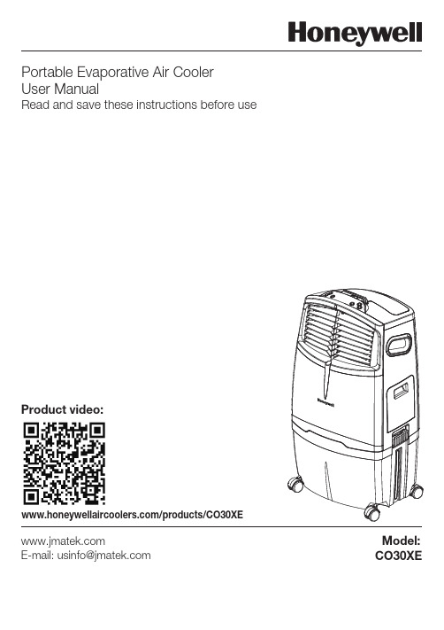
CO30XE/products/CO30XEE-mail:*****************Model:Portable Evaporative Air Cooler User ManualRead and save these instructions before useProduct video:6) Casters7) Ice Compartment Lid 8) Rear Grill9) Water Level Indicator 10) Remote Control11) Detachable Water Tank Latch 12) Water Fill Door 13) Drain Plug14) Water Regulator1) Control Panel 2) Handle 3) Louvers 4) Water Tank5) Power Cord & Plug USE & OPERATIONCONTROL PANELFUNCTION BUTTONSPOWERPress the button to turn the unit on. The cooler will start automatically at medium speed. After a few seconds the speed will switch to low. To turn the unit off, press the button again.SPEEDPress the SPEED button repeatedly to change the speed between High - Medium - Low.The indicator light will show the selected speed:COOLPress the COOL button until is illuminated on the display screen. This activates evaporative cooling. The water pump will operate and you will feel the cooler air after the Honeycomb Cooling Media is completely wet. When the is not illuminated on the display screen, the unit switches to a fan only mode, without evaporative cooling.WARNING -- READ AND SAVE THE AIR COOLER SAFETY & MAINTENANCE GUIDE AND USER MANUAL BEFORE USING THIS PRODUCT. FAILURE TO FOLLOW THESE INSTRUCTIONS MAY DAMAGE AND/ OR IMPAIR ITS OPERATION AND VOID THE WARRANTY. IN CASE THERE IS ANY INCONSISTENCY OR CONFLICT BETWEEN THE ENGLISH VERSION AND ANY OTHER LANGUAGE VERSION OF THE CONTENT OF THIS MATERIAL, THE ENGLISH VERSION SHALL PREVAIL.Icons on Display ScreenNaturalHigh speed Swing TimerWARNING: Please ensure sufficient water is in the water tank otherwise you may hear a Low Water Alarm and the cooler will start in a Fan only mode without evaporative cooling.TIMERPress the TIMER button until the desired time duration setting is selected. When the set time haspassed, the unit will automatically turn off (unit remains in Standby mode until power cord is unplugged from electrical socket). The TIMER function allows you to program the unit for up to 7.5 hours of use.SWINGPress the SWING button until is illuminated on the display screen. The louvers will begin to move left to right automatically.Vertical Air Flow - You can manually adjust the louvers to change vertical air flow.NATURALPress the NATURAL button until is illuminated on the display screen. The fan will randomly change between High, Medium and Low speeds to mimic a natural breeze.REMOTE CONTROLROOM COOLING AND HUMIDIFYINGLOUVER MOVEMENT: ON / OFF: Low / Medium / High: Controls cooling or fan option : Controls the motion of the louvers: Controls the Timer function for automatic off : Turns on Natural modeThe remote control requires AAA (2 x 1.5V) batteries for replacement.Open the battery compartment at the back of the remote control and insert the batteries inside. Care must be taken to insert the batteries according to the correct polarity (+ / –) markings shown inside the battery compartment.Always point the remote control signal transmitter towards the unit when operating. Make sure that the signal path is not obstructed.Remove the batteries if the unit is not going to be used for an extended period of time.Do not drop the remote control.Do not mix different types of batteries such as alkaline, carbon-zinc, or rechargeable batteries.t t t t t t Note:POWER SPEED COOL SWING TIMER NATURAL In cooling mode, Honeywell Air Coolers provide cool, moist air through the evaporation of water. There is a manual Water Regulator knob located in the ice compartment of the unit. This allows you to adjust the amount of water pumped over the Honeycomb Cooling Media, thus helping to control cooling and humidification levels.When the Water Regulator is set to MIN, the water pump distributes a minimal amount of water to the Honeycomb Cooling Media. This results in less water evaporation and reduces the cooling effect.When the Water Regulator is set to MAX, the water pump distributes the maximum amount of water to the Honeycomb Cooling Media. This results in maximum water evaporation and greater cooling performance.Do not mix old and new batteries.Do not recharge the battery.Exhausted batteries are to be removed from the product and safely disposed of as per local regulations.Do not dispose of batteries in fire. Batteries may explode or leak.WARNING: Caution for ingestion of the small battery. Keep away from children and animals. t t t t FILLING WITH WATERCOOLER LOCATIONCAUTION:Unplug the unit from the electrical power outlet before emptying or refilling the water tank.Open the Water Fill Door located on the side of the unit.The Water Level Indicator is located at the side of the unit. Refill the water tank when water level is low. Do not fill water above the "Max." water level mark to avoid water droplets collecting on the louvers. Check the water level in the tank before running the COOL function. Make sure that the water in the tank is above the minimum water level mark. Running the unit in COOL mode with inadequate water may cause pump failure.Note: The water capacity refers to the total volume of water that can be contained within the air cooler water tank and water distribution system. The water capacity in the tank at the “Max.” indicator level may be lower than the actual water capacity of the air cooler.Make sure to position the air cooler correctly before you set up and start using the product. Please referto the COOLER LOCATION section of the separate Safety & Maintenance Guide.LOW WATER ALARMThe unit is equipped with a low water sensor. In Cooling Mode, when water in the tank is below the minimum level, you will hear a beeping sound and the will flash continuously. The unit will automatically pause evaporative cooling.Refill the water tank to deactivate the alarm in cooling mode. First switch OFF the unit and unplug from the power outlet. Fill the water tank with water above the minimum water level mark. Plug in and switch ON again.To deactivate the alarm and continue using the unit as a fan (without evaporative cooling), switch the unit OFF and then ON again. The Low Water Alarm will not activate in Fan only mode. The Low Water Alarm will sound again if the COOL function is activated while the water tank is still empty.Note: If ice is available, you may add ice in the top ice compartment to enhance the cooling performance.WARNING: Do not fill water tank with dirty water or salt water. This can damage the unit and Honeycomb media.CLEANING THE CARBON DUST FILTER* AND HONEYCOMB COOLING MEDIA The appliance is supplied with a Carbon Dust Filter* &Honeycomb Cooling Media.The Carbon Dust Filter* and Honeycomb Cooling Media are located inside the Rear Grill. See Figure 1 for instructions on how to remove them from the unit for cleaning and maintenance.Do not run the unit in COOL mode with stale water in the tank. You must empty the water tank and refill with fresh water, especially if the tank has not been cleaned in a long time.The cleaning frequency for the Honeycomb media depends on local air and water conditions. In areas where the mineral content of water is high, mineral deposits may build up on the Honeycomb Cooling Media and restrict air flow. Draining the water tank and refilling with fresh water at least once a week will help reduce mineral deposits. If mineral deposits remain on the Honeycomb Cooling Media, the media should be removed and washed under fresh water. The media should be cleaned every two months or sooner, depending on your needs.For best results allow the Honeycomb Cooling Media to dry after each use by turning off the cool function 15 minutes before turning the unit off.t t t t t Figure 1:Remove all the screws from the Rear Grill of the Air Cooler.Carefully pull out the rear grill from the cooler.Slide out the Carbon Dust Filter* and clean with water.The Honeycomb Cooling Media is secured on the Honeycomb Frame by a Horizontal Bar that is fixed in place by two screws. Remove these two screws torelease the Horizontal Bar and slide the Honeycomb out of the frame.Replace or clean media with water and a damp cloth as needed.WARNING: DO NOT operate the Air Cooler when the Rear Grill or Honeycomb Frame is removed from the Air Cooler, or if there is a loose-fitting Rear Grill orHoneycomb Frame. Doing so can cause serious injury or dangerous electrical shock.1.2.3.4.5.Removing the Carbon Dust Filter*/ HoneycombCooling Media:Honeycomb Cooling MediaFrame*Applicable for models with Carbon Dust Filter only.CLEANING & DRAINING THE WATER TANKWARNING:Before cleaning the unit, switch the unit OFF and disconnect from the electrical socket.Below are instructions on how to clean and maintain your air cooler. If the cooler will not be used for a long period of time, please refer to the STORAGE & MAINTENANCE GUIDELINES located in the separate Safety & Maintenance Guide.Move the unit to a location where the water can be drained. Remove the cap from the Drain plug located at the bottom of the unit. Allow the tank to empty.Refill the water tank with clean water and drain it completely.Refill the water tank with clean water, up to the maximum level.Use a damp cloth to remove the dirt and dust from the surface of the unit. Never use corrosive elements or chemicals to clean this product.When the product is not in use, store the unit in a dry place out of direct sunlight.t t t t tModelCO30XEProduct Dimension458 (W) x 352 (D) x 856 (H) mm 18.0 (W) x 13.8 (D) x 33.7 (H) insb l 9.42 / g k 3.11th g i e W t e N V021 - 011e g a t l o V z H 06y c n e u q e r F Ampere 2.4A Wattage288 WFor USA Outdoor Models Only. This appliance is equipped with a GFCI plug.Press the TEST button and then the RESET button once every month to ensure proper operation.Cooling Media HoneycombJMATEK North America LLC Mahwah, New Jersey 07495 USA Phone: 1-800-474-2147 Email:***************** Web: © 2016 JMATEK Limited. All rights reserved.The Honeywell Trademark is used under license from Honeywell International Inc.Honeywell International Inc. makes no representations or warranties with respect to these products.This product is manufactured by Airtek Int'l Corp. Ltd. (subsidiary of JMATEK Ltd.)。
帕塔酷尔飓风型移动式蒸发冷却器用户手册说明书

PORTACOOL CYCLONE OWNER’S MANUALPAC2KCYC01, PACCYC02,PACCYC03, PACCYC04,PACCYC0634OPERATION WARNINGSSAFE OPERATION1) Not for use by children2) Not for use by persons with reduced physical, sensory or mental capabilities3) Not for use by persons who have not reviewed the owner’s manual and familiarized themselves with the operation of the product.To reduce the risk of electric shock, fire, or injury:• Do not operate any evaporative cooler with a damaged cord or plug.• Do not run power cord under carpeting or cover withthrowrugs, runners or similar coverings. Arrange power cord away from traffic areas to avoid tripping hazards.• Read the evaporative cooler’s instructions, owner’s manual and labels throughly before use.• Always unplug the power cord to the evaporative cooler before performing inspections or repairs.• Do not step on or roll over power cord with heavy or sharp objects.• Do not operate evaporative cooler unless all KUUL ® evaporative media is securely in place.• Test the GFCI/GLCI receptacle or breaker monthly to ensure it is functioning properly.• Remove the plug from the electrical receptacle by pulling on the plug, not the power cord.• Operation near open flames or sparks is not recommended.• If operating near open flame or sparks, ensure the pump is continuously running in order to saturate and wet KUUL evaporative media.• Never wash the evaporative cooler’s housing with a garden hose; water may harm the motor or electrical system.• The use of extension cords with your evaporative cooler is not recommended. However , if the owner determines that his or her circumstance or intended use requires the use of an extension cord, the following requirements must be met: - Extension cord must be 14 gauge or greater;- Extension cord must not exceed 50 feet in length; and - Extension cord must be properly grounded.• If the evaporative cooler is damaged or malfunctions, do not continue to operate it. Refer to the warranty, troubleshooting or FAQ sections of this Owner’s Manual, call Portacool, LLC Technical Support at 1-888-266-5243, or email *********************CYCLONE 3000CYCLONE 2000CYCLONE 1000Drain locatedin backDrain locatedunderneathDrain locatedin back Casters CastersWater levelsight tubeAdjustablelouversAdjustablelouversControl panelControl panelWater adjustmentvalveWater adjustmentvalveHose connectionControl panelWater adjustmentvalveHose connection Hose connectionPower cordPower cordWater levelsight tubeCastersAdjustablelouversPower cordWater levelsight windowKUULevaporativemediaKUULevaporativemediaKUULevaporativemediaCYCLONE 2200CYCLONE 3200Drain locatedin backDrain locatedunderneathCastersCastersWater levelsight tubeAdjustablelouversAdjustablelouversControl panelControl panelWater adjustmentvalveWater adjustmentvalveHose connectionHose connectionPower cordPower cordWater levelsight tubeKUULevaporativemediaKUULevaporativemediaPLACEMENT1) Make sure there is a clear, unobstructed path in front of the evaporative cooler to provide maximum airflow.2) If the evaporative cooler is positioned on a raised platform, ensure the platform is stable, well constructed and will not allowthe evaporative cooler to tip over. Ensure it allows for the full weight of the evaporative cooler, including a tank full of water. The evaporative cooler must be level and in the upright position and the casters should be locked to prevent movement.3) If placed near a wall or other obstruction, position the evaporative cooler a minimum of 3 feet (0.9 meters) from the wall or obstruction with the KUUL® evaporative media facing the wall. This allows the unrestricted flow of warm air to the KUUL evaporative media. When using multiple evaporative coolers in close proximity, be sure to aim each evaporative cooler so the air flows complement each other to achieve maximum cooling capacity.STARTING THE PUMP AND ADJUSTING THE WATER FLOWOnce the tank is full of water, flip the pump switch into the on position. The water level in the tank may drop suddenly and restart the flow of supply water. This is a normal condition, as the KUUL evaporative media requires a large amount of water for proper wetting.New KUUL evaporative media requires an initial ‘breaking-in’ period before the KUUL evaporative media begins readily absorbing water. It may require up to a week to achieve maximum efficiency.It is important to ensure the water flow to the KUUL evaporative media is properly adjusted when first starting the water flow in the evaporative cooler. Use the water adjustment valve (see Quick Setup section) to increase or decrease water flow. Proper water adjustment should leave the KUUL evaporative media saturated with water, but not flooded. Your KUUL evaporative media should appear wet, with one or two dry streaks across surface. If water is splashing from the evaporative media, decrease the water flow.When turning the evaporative cooler off at the end of the day or week, the pump should be turned off about 15 minutes before the fan to allow the KUUL evaporative media to dry.STARTING THE PORTACOOL EVAPORATIVE COOLERStart the fan by turning the fan switch to either the high or low position. Before starting your evaporative cooler, make sure the casters are in locked position.ORDER PARTS ONLINE While the rugged, corrosion-resistant construction ensures low maintenance will be required, keeping your evaporative cooler clean will ensure it stays in peak operating condition.DAILY MAINTENANCEThe pump should be turned off approximately 15 minutes before the fan is turned off, which allows the KUUL ®evaporative media to dry out. Ensuring your KUUL evaporative media is dry at the end of the day not only extends its life, it also helps control the growth of mildew, mold, bacteria and other odor-causing elements.WEEKLY MAINTENANCEYour Portacool portable evaporative cooler should be shut down and the tank should be drained once a week. Closing the water adjustment valve and removing the drain plug will accomplish this. Once the tank is drained and the power disconnected, the KUUL evaporative media may be removed to allow cleaning of the tank, where dust may collect over time. Replace KUUL evaporative media in correct airflow direction, referring to the label on the KUUL evaporative media.STORAGE1) Drain all water from the tank and wipe the tank clean, ensuring the KUUL evaporative media and tank are dry. 2) Roll up the power cord and secure it to ensure it will not be rolled over, tripped over or caught in equipment. 3) Cover the evaporative cooler completely to prevent dust build-up and store in a dry area. This also helps to preventdamage to the KUUL evaporative media. Optional protective covers are available from yourdistributor or at .ORDER PARTS ONLINETurn off all power to your evaporative cooler before attempting to troubleshoot any of the following symptoms. For problems not listed, please contact customer service.SYMPTOM Evaporative cooler fails to start or deliver airEvaporative cooler starts, but air deliveryis inadequateWater draining from the evaporative coolerKnocking, shaking, or rattling soundsREMEDY1. Check powerA. Reset breaker*B. Reset GFCI*C. Plug in cord(s) or replace if damaged* If condition persists, call electrician2. Replace motor1. Move evaporative cooler at least three feetfrom the wall2. Replace fan motor3. Replace capacitor1. Replace float valve2. Tighten plug1. Check and tighten where needed2. Inspect and adjust, or replace fan blade POSSIBLE CAUSES1. No electricity to the evaporative coolerA. Circuit breaker trippedB. GFCI trippedC. Power unplugged or damaged2. Motor overheated and/or frozen1. KUUL evaporative media side of hte evaporativecooler is too close to a wall2. Fan motor failure3. Capacitor failure1. Seat in float valve leaking2. Drain plug not tight1. Loose parts2. Fan blade rubbing shroudORDER PARTSONLINESYMPTOMMusty or unpleasant odorWater droplets in the air streamSwitch keeps returning to “off” positionPOSSIBLE CAUSES1. Stale or stagnant water in tank2. KUUL evaporative media is mildewed or clogged 1. Too much water delivered to KUUL evaporative media2. Leaking hose1. Switch boot is too tightREMEDY1. Drain, flush and clean tank2. Replace KUUL evaporative media1. Make sure KUUL evaporative mediais properly positioned in the frames and evaporative cooler is level 2. Tighten connection or replace hose 1. Gently pull switch to stretch plastic outTECHNICAL SUPPORTTechnical support and service is available directly from your distributor or call Portacool, LLC Technical Support Hot Line at 888-266-5243 for the distributor nearest you. You may also contact the Support Hot Line for consultation on troubleshooting and parts replacement.Please have serial number and model number of cooler available.WARRANTY AND REPLACEMENT PARTSPORTACOOL™ EVAPORATIVE COOLER LIMITED WARRANTYFor one (1) year from date of purchase, Portacool, LLC (hereafter “Portacool”) warrants any original component part or parts of its Portacool™ portable evaporative coolers (the “Equipment”) that are found, upon examination by factory-authorized personnel, to be defective in material or workmanship.If the Equipment and/or its original component parts, including product housings, develop a defect covered by this limited warranty within the applicable time periods described above, the same may be repaired or replaced at the option of Portacool.All transportation charges for shipment of the Equipment and/or its component parts that are submitted for replacement or repair under this warranty must be borne by the purchaser.This warranty is void if: i) the Equipment and/or its component parts are found to have been misused, abused, repaired by or tampered with by unqualified personnel; ii) any of the product’s component parts have been replaced with parts that were not authorized Portacool replacement parts; iii) the product has been modified in any way (other than repairs made by qualified individuals with Portacool replacement parts); iv) the product has not been appropriately registered by its original purchaser; or v) the customer cannot show proof of purchase as the product’s original owner.PORTACOOL LIMITATION OF LIABILITYIN THE CASE OF A BREACH OF ANY IMPLIED OR WRITTEN WARRANTY RELATING TO THE EQUIPMENT AND/OR ITS COMPONENT PARTS, PORTACOOL SHALL NOT BE LIABLE FOR ANY INCIDENTAL OR CONSEQUENTIAL DAMAGES, AND THE LIMITS OF LIABILITY AGAINST PORTACOOL FOR ANY SUCH BREACH SHALL NOT EXCEED THE COST OF REPLACEMENT OR REPAIR OF THE EQUIPMENT.Q. What assembly is required?A. None. Your Portacool portable evaporative cooler is ready to use right out of the box.Q. How do I prepare my Portacool portable evaporative cooler for storage?A. Drain the evaporative cooler, wipe out the tank to ensure it is dry and clean, dry out the KUUL® evaporative media, cover the evaporative cooler and store in a dry place.Q. I ran my evaporative cooler for the first time and there is an unpleasant odor!A. The KUUL evaporative media, located in the back of your Portacool portable evaporative cooler, has never been wet before. The KUUL evaporative media will emit an odor the first time you wet it that lasts approximately one to three weeks. Keep your evaporative cooler in an open area until the odor goes awayor put a capful of laundry softener directly in the tank. After approximately two weeks of operation, the odor should disappear. Q. My Portacool portable evaporative cooler isn’t putting out cool air.A. First, make sure the water source and electricity sourceare connected and working. Second, check to see if the KUUL evaporative media is damp. If not, adjust the water flow with the water adjustment valve. Third, make sure there is water in the tank. It should be allowed to fill before you turn the pump on.Q. What is the best environment to product the most cool air from my Portacool portable evaporative cooler?A. For optimum performance, the temperature should be 85˚ F or higher and the relative humidity should be below 75%. However, Portacool portable evaporative coolers will reduce the temperature in almost any environment, making it more pleasant.Q. How often does the KUUL evaporative media need to be replaced in my evaporative cooler?A. Depending on the quality of maintenance, water quality and frequency of use, KUUL evaporative media typically lasts up to five years.Q. What is the difference between evaporative cooler and misting systems?A. Misting systems spray a shower of water into the air that collects on people, objects, equipment, floors, etc. Portacool portable evaporative coolers use the process of evaporation to produce cooler air, but do not discharge a mist.Q. Where can I buy replacement parts and accessories for my Portacool portable evaporative cooler?A. Replacement parts may be purchased directly from Portacool Parts/Technical Support department or www.portacoolparts.com. You may also buy replacement parts from any Portacool distributor.Q. What amount of moisture is added to the air by my evaporative cooler?A. An increase in humidity of approximately two to five percentis produced, depending on the temperature and humidity of the environment. This increase is not noticeable in a ventilated area where the air produced by the cooler is exhausted.Q. How long will the water supply last in my evaporative cooler’s tank?A. With no direct water source available, the water will evaporate in a filled tank within two to 10 hours of operation, depending on the water capacity of the evaporative cooler, ambient conditions, temperature and humidity. A water source for refilling the tank is recommended by the manufacturer.Q. Where are the model and serial numbers found?A. The model number can be found on a metal plate on the outside of the cooler. Model numbers begin with the letters “PAC.” Serial numbers are all-digits.Q. What if my question is not answered here?A. Our U.S.-based Tech Support staff is available 8 a.m. to 5 p.m. Central Time, Monday though Friday at 1-888-COOL-AID or you ************************************.HOW TO REPLACE YOUR KUUL EVAPORATIVE MEDIAStep 1Be sure to unplug your Portacool portable evaporative cooler before doing any maintenance. Lock the casters to keep your evaporative cooler from moving while you are working. Remove the flap and KUUL® evaporative media from the evaporative cooler. The flap is attached at the top of the evaporative cooler with three screws. Remove the three screws and set the flap aside.Step 2All KUUL evaporative media must be removed before accessing the inside of the evaporative cooler. Remove the center set of KUUL evaporative media first by grasping at the top and tilting it out and away from the evaporative cooler. While tilting the KUUL evaporative media out, lift it up and out of the evaporative cooler.Step 3Remove remaining KUUL evaporative media in the same manner. Set aside in a safe place to prevent damage while out of the evaporative cooler. Once all the KUUL evaporative media has been removed, you should have access to the inside of the evaporative cooler and internal components.Additional parts can be found at DATE OF PURCHASEMODEL NUMBERSERIAL NUMBERYOUR NAMEADDRESSCITYSTATE ZIP CODE PHONE NUMBERWHO DID YOU PURCHASE FROM?EMAIL Please complete this form and mail in a stamped envelope to:Portacool, 711 FM 2468, Center , TX 75935 or register online at: /support ( ) - @REGISTER YOUR PROD UCT AT WWW VISIT OR CALL 1-936-598-5651FOR MORE INFORMATION CUSTOMER SERVICE CONTACT 1-936-598-5651 • 1-800-695-2942********************TECHNICAL/PARTS CONTACT 1-936-598-5651 • 1-800-695-2942*********************Portacool, LLC • Manufacturer of Portacool™ portable evaporative coolers andKUUL ® evaporative media711 FM 2468 • Center , Texas 75935 • 936-598-5651 • MANR0002The manual is available in other languages. To download a digital copy, please visit .El manual está disponible en otros idiomas. Para descargar una copia digital, por favor visite .Le manuel est disponible en d’autres langues. Pour télécharger une copie numérique, se il vous plaît visitez . ليمحتل .ىرخألا تاغللا يف حاتم وه ليلدلاو ةرايز ىجري ،ةيمقر ةخسنREGISTER YOUR PROD UCT AT WWW 。
蒸发式冷风扇使用方法
蒸发式冷风扇使用方法
蒸发式冷风扇是一种利用水的蒸发来降低室温的设备。
以下是使用蒸发式冷风扇的步骤:
1. 将蒸发式冷风扇放置在需要降温的房间内,确保其稳固。
2. 将蒸发式冷风扇的水箱加满凉水,同时加入一定量的冷风扇专用清洁剂,以清洁水箱内部。
3. 打开蒸发式冷风扇的电源,调节风扇的风速和出风口方向。
4. 等待几分钟,当水开始从出水口流出并浸湿冷风扇的吸水滤芯时,冷风扇开始工作。
此时,风扇会将空气吹过湿润的吸水滤芯,使空气中的水分蒸发,从而达到降低室温的效果。
5. 需要注意的是,当室内温度较高时,蒸发式冷风扇可能无法完全降低室温。
此时,可以开启空调或打开窗户透气,以帮助蒸发式冷风扇更好地降低室温。
6. 在使用完毕后,关闭蒸发式冷风扇的电源,并倒掉水箱内的水,将吸水滤芯拆下并清洗干净,以便下次使用。
以上就是使用蒸发式冷风扇的方法,希望对您有所帮助。
蒸发冷使用说明

一前言
本说明书是以一般食品加工、冷冻、啤酒、饮料、石油、化工、医药等行业用于 SLC 系列 蒸发式冷凝器作为对象,是确保安全使用本产品的指南。 � 在本产品使用前,一定要先阅读本说明书,在充分了解了运行、检查、及修配方面的基础上使用。 � � 由于产品的改良,本书的内容与机器的说明会出现异议的情况,请提前了解这种情况。 � � 如果操作过程与本说明书不符,会造成重伤、死亡等重大事故。 � � 在本说明书中,很多地方都提到如下所示的注意事项。 � � 特别是确保安全的注意事项,应该在充分理解的基础上再进行操作。 � 在不注意的情况下使用本机器,会发生重伤、死亡等重大事故,造成严重伤害。
� 操作者及保养人员在操作和保养机器之前请认真阅读本说明书。
� 本说明书请保存在机器附近,以便随时查阅。
� 在没有完全理解本说明书之前,请不要对机器进行操作、保养。
� 本说索取。
18-2
二 安全注意事项
(1)请委托专业销售厂家或专业公司进行安装。自己安装有不完备之处,则会引起漏水、触电、火灾等运行故障。 (2)电加热器等另售商品请一定要使用本公司指定产品。万一自己安装有不完备之处,则会造成漏水、触电、火 灾等运行故障,请委托专业厂家进行安装。 (3)请接地线。地线不能与燃气管、水道管、避雷针及电话地线等相连接。 地线不完备则会造成触电等运行事故。 (4)根据电气设备技术标准规定,请安装漏电断路器。如不安装则会造成触电等运行事故。 (5)请不要放置于可能有可燃性气体泄漏的场所。万一泄漏的气体滞留于塔周围,则易发生火灾等事故。 (6)标准型蒸发冷凝器不要放置于特殊环境中(温泉地带、海岸地区、多油的场所等),否则会由于腐蚀等造成触 电、火灾等运行事故。 (7)要确保溢流管及排水配管畅通,若不畅通,则会造成漏水而波及其它设备、设施及财产。 (8)在保养和检查时,一定要关闭机器,切断电源。在内部高速运转或正处在控制状态中风机突然运转都会出现 受伤、触电等现象。 (9)不要把手或木棒伸进空气的进出口。内部风机在高速运转时会造成伤害。 (10)出现异常时(烧焦等),应立即停止运转,切断电源,与代售商或生产厂家取得联系,如果在异常状态下继 续运转则会造成故障、触电、火灾等。 (11)当手湿时不要接触开关,否则会触电。 (12)长期使用中请注意安装台、地脚螺栓是否有损伤,如果在螺栓损伤的状态下放置蒸发冷凝器则会翻倒而引起
蒸发式冷凝器操作规程

蒸发式冷凝器操作规程1. 引言蒸发式冷凝器在化工和制药等行业中被广泛应用。
它通过将冷凝介质直接喷洒在加热表面,利用蒸发吸热原理,将热量从冷凝器表面带走,从而实现冷凝和热回收的目的。
为了确保蒸发式冷凝器的正常运行和操作安全,制定本操作规程。
2. 蒸发式冷凝器操作流程2.1 准备工作•检查设备的运行状态,确保冷凝器处于正常工作状态;•检查冷凝介质供应系统,确保冷凝介质充足;•对于新的操作人员,应经过培训并了解冷凝器的操作流程和注意事项。
2.2 开始操作•打开冷凝介质供应系统,并调整冷凝介质的流量以满足工艺要求;•打开冷凝器进料阀门,使冷凝介质流入冷凝器;•开始启动冷凝器,确保冷凝器运行平稳。
2.3 监控与调整•监测冷凝器的运行状态,包括温度、压力等参数,并记录;•根据实际情况,调整冷凝介质的流量和温度,以保持冷凝器的正常工作;•定期清洗冷凝器,避免冷凝介质堆积和污染。
2.4 停止操作•停止冷凝器的供给冷凝介质;•关闭冷凝器的进料阀门;•停止冷凝器的运行;•关闭冷凝介质供应系统。
3. 安全注意事项•操作人员应熟悉蒸发式冷凝器的工作原理和操作规程;•在操作过程中,应佩戴适当的防护设备,如手套、护目镜等;•避免将手部或其他物体接近冷凝介质的喷洒区域,以免发生意外伤害;•定期检查冷凝器的运行状态和设备安全性,如有异常及时报修;•严禁私自拆卸或修改冷凝器的任何部件。
4. 维护保养4.1 清洗冷凝器•开始清洗前,确保冷凝器已停止运行,并断开供电;•采用专用的清洗溶液对冷凝器进行清洗,按照清洗溶液的使用说明进行操作;•清洗结束后,用清水冲洗冷凝器,确保清洗溶液彻底清除;•冷凝器干燥后,可重新组装并恢复正常使用。
4.2 定期维护•对冷凝器进行定期维护,可以延长其使用寿命和提高工作效率;•清洗冷凝器的冷凝介质喷洒器,以防止堵塞;•检查冷凝介质供应系统的管道和阀门,确保畅通;•检查冷凝器的传热管表面,如有腐蚀和漏损应及时处理。
复合式蒸发空冷

设备运行注意事项
(1) 不建议采取停止设备某台风机的方法来进行风量调节,因 为这样会造成风的短路而影响设备的换热。若采用此方法进行 风量调节,则应采取必要措施避免风的短路现象。
设备运行注意事项
(2) 水泵出口调节阀全部打开,并不意味着水泵的工作点和效 率达到最佳当出口的开启度过大,会使水泵工作在超流量状态, 使得电机的工作电流过大,引起电机发热。出口调节阀的开启 度在2/3较为合适,保持水箱的水位不低于水箱高度的4/5,过 低的水位会让水泵产生气蚀现象,并使得设备的喷淋水量不足, 影响换热。
复合型蒸发式冷却 器操作培训
一、高效复合型蒸发式冷却技术介绍
二、高效复合型蒸发式冷却器与传统冷却器技术参数 及对比 三、高效复合型蒸发式冷却器现场布置图 四、设备使用前的准备工作
五、设备运行
六、设备运行注意事项 七、高效复合型蒸发式开停机操作步骤
高效复合型蒸发式冷却技术介绍
高效复合型蒸发式冷却技术,以潜热换热先进机理为 基础,将蒸发换热和空冷换热优化组合,实现一项动力两 级利用。是以水和空气为冷却介质,利用循环冷却水的蒸 发潜热和含水蒸汽的空气带走被冷却高温介质中的热量, 其中既有风冷冷凝器的显热换热,又有蒸发式冷凝器的潜 热换热,而传统的壳管式水冷器只有靠水的温升来进行换 热。在相同的换热负荷下,与传统水冷系统相比,可以节 水30%-70%,节电30%-60%。 显著特点是高温工质在进入盘管组件前,先通过翅片 部件,利用从盘管和热交换器中排出的低温湿空气排入大 气前对其进行大风量、大温差的冷却,使翅片管内的高温 工质得到预冷后进入蒸发冷凝器冷却。
(3) 水箱中的水位应处于水箱总高的4/5的位置,且水质清洁。 (4) 如果过滤器被杂物缠绕过多,请拆下过滤器清洗后重新装 上。 (5) 检查喷头是否有损坏,如有更换后方可开机。 (6) 用手转动风机是否运转正常。 (7) 在每次重新运行前检查浮球阀开、停位置是否正常。 因出厂时已加过润滑油)。 (8) 设备水泵起动前,应手动盘车后再行通电运行,检查转动 方向是否与水泵壳上箭头方向一致,否则调整后再起动。
2.5、能源项目蒸发式冷却器技术规格书
蒸发式冷却器技术规格书一、安装位置及环境条件:1、安装位置:高炉软水循环系统用7台蒸发式冷却器露天布置在循环泵房屋顶上,屋顶相对高度10m左右。
高炉循环水泵房屋面大小为12m×75m,蒸发式空冷器布置在此范围内,并应考虑总管及检修位置。
连铸软水循环水系统用3台蒸发式冷却器露天布置在泵房吸水井上。
2、机组环境多尘、含多种轻腐蚀气体(如SO2、H2S等)3、蒸发式空冷器的选型要保证夏季最热月频率为10%气象条件下蒸发式冷却器出水水温。
4、当地主要气象条件阿拉尔冬季寒冷,夏季炎热,降水量稀少,蒸发强烈,气候干燥,属温带极干旱荒漠气候区。
根据阿拉尔气象站多年观测的气象资料表明,阿拉尔全年盛行东北风,夏季多西北风,年平均气温一般在10℃~11℃左右,年最高气温在39。
2℃,年平均降水量42。
4mm,年平均相对湿度55。
2%,最大积雪厚度3。
0cm,最大冻土深度78cm。
气温:年平均气温: 10.8°C最热月平均气温: 24.8°C最冷月平均气温: -7.8 °C极端最高气温: 40.6 °C极端最低气温: -28.4°C历年平均最多风向: NE(东北);历年最大风力: 9~10级(25m/s)历年平均降雪量: 3.2mm雨量:年最大降雨量: 91.9mm年最平均降雨量: 48.6mm年蒸发量: 2010.6 mm月最大降水量: 32.0 mm日最大降水量: 31.8 mm风:冬季平均风速: 1.2 m/s夏季平均风速: 2.1 m/s瞬时最大风速: 25 m/s风向:年主导风向:东北最大积雪深度: 8 cm最大冻土深度: 78cm标准冻土深度: 55cm年雷暴天气: 33天大气压:冬季大气压力: 907.8 hPa夏季大气压力: 893.5 hPa基本风压: 0.45KN/m2基本雪压: 0.25KN/m2地震设防烈度: 6度室外计算干球温度(夏季空气调节日平均):26℃夏季室外平均每年不保证50小时的湿球温度: 21℃湿度:最热月平均相对湿度: 51%最冷月平均相对湿度: 66%二、设备规格、主要技术参数及数量1、设备名称:蒸发式冷却器2、设备型号:ZP9×33、设备数量:10台(高炉系统7台、连铸系统3台)4、主要技术参数1)单台冷却水量:Q=500m3/h2)单台喷淋水量:160 m3/h3)总的喷淋水量:高炉系统1120m3/h、连铸系统480m3/h4)进水温度:高炉系统T1=55℃、连铸系统T1=48℃5)出水温度:高炉系统T2≤45℃、连铸系统T2≤38℃6)工作压力:高炉系统1.0Mpa、连铸系统1.6 Mpa7)管程压降:≤0.05Mpa8)风机要求:电压:380V,电机防护等级:IP54,绝缘等级F级。
ACWC-090-Q-EXCH1 90,000 BTU HR单阶空冷蒸发式移动水冷机系统说明书
Model: ACWC-090-Q-EXCH1-__2-__3-__4Description:Single stage air-cooled portable water chiller system with additional process system heat exchanger. System capacity indicated on table is the approximate BTU/hr based on a leaving fluid temperature of 50°F with an ambient air temperature of 95°F.CAPACITY90,000 BTU /HR±5% AT 50° LCWT / 95°F AMBIENTCOMPRESSOR / REFRIGERANT HERMETIC SCROLL / R410ACONDENSER FANS / AIRFLOW 1 / 5700 CFMCONDENSER COILS TYPE COPPER TUBE / ALUMINUM FINEVAPORATOR TYPE STAINLESS STEEL / COPPER BRAZEDHEAT EXCHANGER TYPE STAINLESS STEEL / COPPER BRAZEDFLUID CONNECTIONS 1” MNPT (IN/OUT)ELECTRICAL: V - Ø - HZ COMP RLA / LRA FAN FLA PUMP FLA MCA MOCP - 5 230 - 3 - 60 27.9 164 5.3 3.4 43.5 70- 6 460 - 3 - 60 13.6 100 2.2 1.7 20.1 30 PUMP HP / OUTPUT 1.0 HP / 30 GPM @ 30 PSITANK SIZE / CONSTRUCTION 41 GALLON / 304 STAINLESS STEEL TANK WITH LID DIMENSIONS 66” L x 45” W x 56” HWEIGHT (APPROX.) 1000 LBSNote: All specifications subject to change without notice. Specify voltage and ambient condition upon ordering.MCA: Minimum circuit amps per UL 1995. MOCP: Maximum overcurrent protective device per UL 1995. STANDARD FEATURES:•Controls: Electronic programmed temperature controller with constant (set point & process) temperature readout.•Refrigeration Components: Efficient scroll compressors, sight glass/moisture indicators, balanced port expansion valves, filter drier, pump down valves, fan cycling head pressure controls.•Process Fluid Components: Heat exchanger for separation of chilled fluid circuit from process fluid circuit.Bronze “Y” strainer with 20 mesh stainless steel screen. Pumps are stainless steel centrifugal. Tanks areinsulated with shoe box lid, fill port, and level sight glass. Portable systems will include a flow control valve. •Safety Controls: High and low refrigerant pressure, high and low fluid temperature, freeze, low water flow, overloads for compressor and fan motors, safety fuses or overloads for pump.•Construction: Welded steel powder coated frame and full metal cabinet, copper piping connections. •Warranty: One year parts / five year compressor.SUITABLE AMBIENT CONDITIONS/FEATURES:•IND: Indoor use only. Casters on frame.•40: Suitable for outdoor use with an ambient of 40°F ambient.•0: Suitable for outdoor use to 0°F ambient.•M20: Suitable for outdoor use to -20°F ambient. Includes hot gas bypass.1 Flow Design (_=Portable, ST=Stationary, RF=Reverse Flow, EXCH=Extra Heat Exchanger, DP=Dual Pump, DR=Dual Return)2 Leaving Fluid Temperature (_=Standard, LT=Low Temperature-specify lowest temperature in °F)3 Ambient Temperature Conditions (see above)4 Electrical Power Code (see above)TechSpec_ACWC-090-Q-EXCH-_-_ _-(0620).doc.docxNOTES-Unit should be installed with at least 2' clearance on all sides and a minimum of 5' clear air space above the unit -Dimensions are approximate. (inches)-Casters (Optional)-All specifications subject to change without notice.COLD SHOT CHILLERSDRAWN ENGINEERINGISSUEDSIZE DIMENSION NOTES DWG NO REVA Dimensions are in inches Unless otherwise specified. +-¼”INSTALLATION DRAWING ACWC-090-Q_ (Typical)16/4/2020SCALENONEDWG-INST_ACWC-090-Q-EXCH-(0620).vsdSHEET1 / Front-Back-Top-Sides-Q-EXCHRIGHT SIDE VIEWFRONT VIEWBACK VIEW 67.0046.00LEFT SIDE VIEWTOP VIEWControl Panel SideControl SwitchInlet(From Process)(MNPT)Outlet(To Process)(MNPT)Temperature Controller54.00Control Panel。
蒸发式冷风机说明书
蒸发式冷风机说明书
蒸发式冷风机是一种新型的空气净化器,主要适用于室内温度高且空气污染严重的环境中。
该产品采用蒸发式冷却技术,可以有效地降低室内温度,提供清新、凉爽、健康的空气环境。
蒸发式冷风机的使用非常简单,只需要将产品放置在室内合适的位置,并连接电源即可。
在使用过程中,用户可以根据需要选择不同的风速和运行模式,以适应室内不同的温度和湿度环境。
此外,该产品还配备了可拆卸式双面过滤网,能够过滤空气中的灰尘、异味、细菌等有害物质,提供更健康的室内空气质量。
虽然蒸发式冷风机具有非常明显的降温效果,但是该产品并不会增加室内的湿度。
相反,它会将空气中的水分分散在空气中,达到一定的湿度平衡,避免干燥或潮湿的室内环境。
总的来说,蒸发式冷风机是一款多功能的空气净化器,不仅能够提供清新凉爽的空气环境,还能够改善室内空气质量,降低温度,让你的居住环境更加健康、舒适。
蒸发器操作步骤说明书

蒸发器操作步骤说明书蒸发器是一种常用于工业生产中的设备,主要用于将液体转化为蒸汽的过程。
该操作步骤说明书将详细描述蒸发器的使用方法和必要的注意事项,以确保操作人员能够正确操作和维护蒸发器。
一、准备工作在使用蒸发器之前,请确保已经完成以下准备工作:1. 检查蒸发器的运行状态和背景信息,包括蒸发器的型号、容量和工作条件等。
2. 根据实际需求将液体加入蒸发器,确认液体的种类和初始温度。
3. 检查蒸发器的冷却系统,确保冷却介质的供应充足,并且冷却系统处于正常工作状态。
二、操作步骤1. 打开蒸发器的进料阀门,将需要蒸发的液体导入蒸发器的加热室。
请确保液体的进料速度合适,避免过快或过慢导致不必要的问题。
2. 启动蒸发器的加热系统,并根据所使用的能源类型选择相应的加热方式。
常见的加热方式包括蒸汽加热、电热阻加热等。
在加热过程中,确保温度的逐渐升高,避免急剧变化。
3. 关注蒸发器的压力变化。
一般情况下,随着温度的升高,蒸发器内部的压力会增加。
请确保蒸发器的压力在设定范围内,并及时调整加热功率以控制蒸发的速率。
4. 监控蒸发器的出料情况。
当液体在加热室内蒸发成蒸汽后,蒸汽会通过出料管道流出。
请确保出料管道通畅,并检查出料液体的温度和流量等参数,以确保操作正常进行。
5. 在使用过程中,及时观察蒸发器的工作状态并记录必要的数据。
例如,温度、压力和流量等参数的变化情况,以便对蒸发器的工作进行评估和调整。
6. 当不再需要使用蒸发器时,首先关闭蒸发器的加热系统,并逐渐减小进料阀门的开度,直至停止液体的进料。
最后将蒸发器内的残余液体排空。
三、安全注意事项在操作蒸发器时,请务必遵循以下安全注意事项:1. 在操作蒸发器之前,确保已经熟悉并理解蒸发器的使用方法和原理。
2. 使用蒸发器时,请佩戴个人防护装备,包括耐酸碱手套、防护眼镜和防滑鞋等。
3. 在加热过程中,避免将皮肤直接接触加热室和出料管道等高温部件。
4. 对于有毒液体的蒸发操作,请确保操作在通风良好的环境下进行,并使用适当的防护设备。
空调蒸发器操作规程(3篇)
第1篇一、操作前准备1. 确认空调系统已正常运行,包括压缩机、冷凝器、膨胀阀等部件。
2. 检查蒸发器外观是否完好,如有破损、脱落等情况,应及时修复或更换。
3. 检查蒸发器周围环境,确保无遮挡物,以便于通风散热。
4. 确认空调系统电源已接通,电压稳定。
5. 熟悉空调蒸发器的结构、原理及操作流程。
二、操作步骤1. 开启空调系统:将空调控制面板上的电源开关置于“开”位置,等待空调系统启动。
2. 设置温度:根据需求调整空调温度,确保室内温度达到设定值。
3. 检查蒸发器运行状态:观察蒸发器表面是否有结霜现象,如有结霜,请调整空调系统风速或温度,以防止蒸发器结霜过厚。
4. 调节风速:根据室内温度和舒适度要求,调整空调系统风速。
风速过高可能导致蒸发器结霜过快,过低则影响空调制冷效果。
5. 检查蒸发器通风:确保蒸发器周围通风良好,避免因通风不畅导致蒸发器散热效果降低。
6. 监测空调系统运行:观察空调系统运行状况,如有异常声音、异味等现象,请立即停机检查。
7. 定期清洗蒸发器:根据使用频率和蒸发器表面脏污程度,定期清洗蒸发器,以提高空调制冷效果和延长使用寿命。
三、注意事项1. 操作过程中,请勿随意拆卸蒸发器,以免损坏设备。
2. 避免将蒸发器表面暴露在阳光下,以免影响空调制冷效果。
3. 定期检查蒸发器周围环境,确保无遮挡物,以免影响空调通风散热。
4. 空调系统运行过程中,请勿关闭门窗,以免影响空调制冷效果。
5. 如发现蒸发器结霜过厚,请立即调整空调系统风速或温度,避免蒸发器结霜过厚导致空调系统故障。
6. 定期对空调系统进行保养,包括清洗蒸发器、检查制冷剂泄漏等,以确保空调系统正常运行。
四、操作结束1. 关闭空调系统:将空调控制面板上的电源开关置于“关”位置,等待空调系统完全停机。
2. 关闭空调系统电源:确保空调系统电源已关闭,以免浪费能源。
3. 清理工作现场:清理操作过程中产生的垃圾,保持工作现场整洁。
4. 检查蒸发器:确认蒸发器表面无破损、脱落等情况,如有异常,请及时处理。
Fincoil FBLG 蒸发冷却器 冷 ради器商品说明说明书
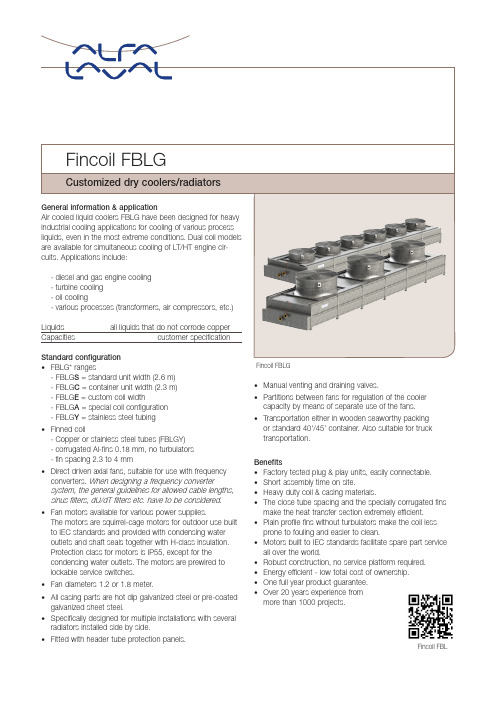
Fincoil FBLG• FBLG* ranges- FBLG S = standard unit width (2.6 m) - FBLG C = container unit width (2.3 m) - FBLG E = custom coil width- FBLG A = special coil configuration - FBLG Y = stainless steel tubing • Finned coil-Copper or stainless steel tubes (FBLGY) -corrugated Al-fins 0.18 mm, no turbulators -fin spacing 2.3 to 4 mm• Direct driven axial fans, suitable for use with frequency converters. When designing a frequency convertersystem, the general guidelines for allowed cable lengths, sinus filters, dU/dT filters etc. have to be considered.• Fan motors available for various power supplies.The motors are squirrel-cage motors for outdoor use built to IEC standards and provided with condensing wateroutlets and shaft seals together with H-class insulation. Protection class for motors is IP55, except for the condensing water outlets. The motors are prewired to lockable service switches.• Fan diameters 1.2 or 1.8 meter.• All casing parts are hot dip galvanized steel or pre-coated galvanized sheet steel.• Specifically designed for multiple installations with several radiators installed side by side.• Fitted with header tube protection panels.Fincoil FBL• Manual venting and draining valves.• Partitions between fans for regulation of the cooler capacity by means of separate use of the fans.• Transportation either in wooden seaworthy packing or standard 40'/45’ container. Also suitable for truck transportation.Benefits• Factory tested plug & play units, easily connectable.• Short assembly time on site.• Heavy duty coil & casing materials.• The close tube spacing and the specially corrugated fins make the heat transfer section extremely efficient.• Plain profile fins without turbulators make the coil less prone to fouling and easier to clean.• Motors built to IEC standards facilitate spare part service all over the world.• Robust construction, no service platform required.• Energy efficient - low total cost of ownership.• One full year product guarantee.• Over 20 years experience from more than 1000 projects.Design pressureDesign pressure 10 barg. Each heat exchanger is leak tested with dry air at 15 barg. Higher design pressures on request.SelectionFBLG liquid coolers are always selected and customized on customer request. Please contact Alfa Laval for selections. DocumentationFor FBLG liquid coolers extensive product & project documentation can be supplied (standard in English). -Mechanical & electrical configuration -Quality, test & material certificates -Project reports & documentation-Installation, operation & maintenance manualsHow to contact Alfa LavalUp-to-date Alfa Laval contact details for all countries are always available on our website at AHE00043EN 1704Code descriptionAlfa Laval is a trademark registered and owned by Alfa Laval Corporate AB. Alfa Laval reserves the right to change specification without prior notification.Options• Coil corrosion protection-epoxy coated aluminium fins (Ep) -copper fins (Cu)-sea water resistant aluminium fins (AlMg) -F-coating, FBGLA only (FC)-Blygold coating, FBGLA only (Bg)• Dual coil models with LT - and HT -circuits • Higher design pressures • Mounting legs (up to 6m)• Handrails and ladder for radiator group • Flexible connection joints• Epoxy painted casing (RAL colours)• Fan speed control -step control (SC)-frequency control (SVC)• Common terminal box located in the end of radiator • Motor protective switch panel• Special fan motors (EX-classed, NEMA etc.)• Motors equipped with -anti-condensation heaters -klixon-PTC thermistors -vibration sensorCertificationsThe Alfa Laval quality system is in accordance with ISO 9001 and ISO 14001. All products are manufactured according to PED regulations.。
蒸发冷使用说明书

5.2 本体安装
①安装场地确定后,请按照样本或所提供的图纸中的基础参考图进行基础施工。 ②安装时请确认使用地脚螺栓在水平地基上固定。 若不固定,则会由于地震、强风等的影响使其倒塌,造成重大事故。
阀门 排水龙头
18-7
5.3 配水管
①试运行时,为方便清洗配水管之需,请在管路中设置旁管回路; ②考虑到有必要清洗填料,希望在冷却塔前安装一个 T 字管; ③为防止给水管冬季冻结,请在给水连接口与阀门中间的最 下部安装排水龙头。
酸消费量 [PH 4.8](mg CaCO 3/ l) 全硬度 硫化物离子 S2- + 氨离子 NH 4 离子状硅 SiO 2 (mg CaCO 3/ l) (mg S2- / l) + (mg NH 4 / l) (mg SiO 2/ l)
18-10
项
目
淋水水基准值
循环水基准值
倾 腐蚀
向 水锈生成 ○ ○
○ ○ ○ ○
硫酸离子 SO
4
(mg SO 4 / l)
○ ○
酸消费量 [PH 4.8](mg CaCO 3/ l) 全硬度 铁 Fe 硫化物离子 + 氨离子 NH 4 离子状硅 SiO 2 S2- (mg CaCO 3/ l) (mg Fe/ l) (mg S2- / l)
○ ○ ○
○
+ (mg NH 4 / l) (mg SiO 2/ l)
目
录
一 前 言.................................................................................................................2 二 安全注意事项 .................................................................................................. 4 三 蒸发冷凝器的原理、构造及说明.................................................................6 四 搬运 ................................................................................................................... 6 五 安装注意事项 .................................................................................................. 6 六 运转准备 ...........................................................................................................8 七 运转方法 .........................................................................................................12 八 保养管理及注意事项 ....................................................................................12 九 冬季运行时的注意事项 ............................................................................... 14 十 有关省能源运转 ............................................................................................ 14 十二 长期停止运转时的注意事项 ...................................................................15 十三 特别注意事项 ............................................................................................ 15 十四 关于补给水量 ............................................................................................ 16
- 1、下载文档前请自行甄别文档内容的完整性,平台不提供额外的编辑、内容补充、找答案等附加服务。
- 2、"仅部分预览"的文档,不可在线预览部分如存在完整性等问题,可反馈申请退款(可完整预览的文档不适用该条件!)。
- 3、如文档侵犯您的权益,请联系客服反馈,我们会尽快为您处理(人工客服工作时间:9:00-18:30)。
蒸 发 式 空 冷 器 操作使用说明蒸发式空冷器操作使用说明安装、使用和维护本设备前,应仔细阅读本使用说明书!一、作用与用途蒸发式空冷器是甲醇(合成氨)生产系统装置中冷却换热设备的最新换代节能产品,它是甲醇(合成氨)生产系统装置中的主要换热设备之一。
又称甲醇(合成氨)冷却器。
蒸发式空冷器的作用是通过冷却盘管的蒸发换热和冷却翅片的空气换热,将生产系统装置中的高温高压气体进行冷却或冷凝成液体、或对较高温度的液体进行冷却。
从而达到生产工艺的要求。
蒸发式冷却器主要应用于甲醇、合成氨等生产系统的合成工序、精馏工序、压缩及变换工序、冰机系统、蒸汽冷凝等关键工艺过程。
分为压缩机级间冷却、甲醇(合成氨)合成气冷却冷凝、甲醇精馏工序冷却(冷凝)、天然气或焦炉煤气转化工序气体冷却、净化工序冷却(冷凝)等。
为年产10万吨及以下、18万吨及以下、30万吨及以下成套设备。
蒸发式空冷器系列产品还适用于炼油、化工、冶金、制冷、轻工、电力、食品、饮料等行业。
二、产品结构与工作原理蒸发式空冷器由空冷式冷却翅片部件、蒸发式冷却盘管部件、水箱及自动补水喷水和水处理装置(包括水泵、自动补水浮球阀、专用喷嘴等)、进风百页窗及轴流风机和自动变频控制器装置(包括进口变频控制器、大图一口径轴流风机)、热浸锌底座及框架、静电喷塑外壳、工艺管口等组成(见图一)。
采用不锈铝或热浸锌翅片、304不锈钢无缝钢管或10#碳钢无缝钢管热浸锌、钢板为热镀锌板或冷轧钢板静电喷塑,水泵、风机配套电机采用防爆户外型,所有螺栓及固定件均进行防腐防锈处理。
蒸发式空冷器是以水和空气为冷却介质,利用循环冷却水的蒸发潜热和含水蒸气的空气带走被冷却(冷凝)气体中或被冷却液体中的热量。
工作时循环冷却水由水泵送至冷却盘管部件上部的喷淋水管中,经喷嘴均匀地喷淋在冷却盘管的外表面,形成一层很薄的水膜。
高温高压气体或高温液体从盘管部件和翅片部件上部集管进入,分配给每一根冷却管,冷却管内的热量通过管壁传给管外表面的水膜,使水膜蒸发,从而实现热量的交换。
而水膜蒸发成为水蒸气后与空气混合成为湿空气,由轴流风机引抽经过冷却翅片部件,对冷却翅片管内的高温高压气体或高温液体进行冷却,从而实现又一次的热量交换。
经过热量交换的湿空气被引抽至设备外进入大气当中,没有被蒸发的循环冷却水吸热后滴落(滴落过程中被冷却)到下部的的水箱内,与补充的新鲜水(由浮球阀自动补给蒸发掉的水份)混合供水泵循环使用。
三、产品特点与关键技术蒸发式空冷器是根据热力学、传热学工作原理,采用蒸发式冷凝器与风冷冷凝器相结合的换热机理,是最新一代的高技术高性能高品质的换热设备。
合理的配管和设计参数优化设计,使流体的流动阻力控制在工艺技术要求的范围以内;利用轴流风机引抽风造成盘管箱内的负压,加大了水分的蒸发从而加强了换热;专用喷嘴使冷却水最大限度的与盘管表面接触换热;冷却翅片部件的设置避开了水在高温状态易结垢现象,从而使蒸发式冷却器的单位面积热负荷得到显著提高,并延长了设备使用寿命;采用了装卸灵活的百页窗,避免了同类产品经过长时间的运行使进风口被堵降低换热效果的现象,更能适应恶劣的工作环境;高效脱水器具有防止腐蚀及生化侵蚀的作用,且其独特的多曲面结构能有效地收集湿空气中的水分,使水的飘逸率可减少到最低。
预冷技术——高温高压气体在冷凝冷却前先进行预冷,通过从蒸发式冷却器盘管中排出的湿空气在排入大气前进行大风量、大温差的冷却,可使高温高压气体得到冷却。
本项技术可达到三个目的:①提高了蒸发式冷却器的冷凝冷却效果,经实践证明传热效果可提高10%以上;②减缓了盘管外表面的结垢现象,提高了设备的使用寿命;③利用自然空气冷却节约了能源。
减缓结垢技术——通过预冷后进入冷凝冷却盘管的气体温度较低,最大限度的避开了水在高温易结垢的现象,减缓了盘管外表面结垢速度;增大了传热表面的配水量,可阻止水在蒸发时的垢质聚集。
冬季干运行技术——由于冷却翅片部件的应用,使设备在冬季停水干运行时性能得到保障,利用了自然界的天然强冷空气能量进行热交换,真正达到了节水节能的效果。
变风量控制技术——传统的冷却器风量控制方法主要是通过调节风机叶片角度或采用双速电机及调节百页窗开启度进行调节。
当需要减少风量时,只能通过放走多余的风量实现,造成能源浪费。
通过最新变频控制技术来控制风机风量,使冷却器节能效果显著。
工艺设计时可在冷却器出口安装温度传感(变送)器,它可以将温度的变化转换成以4~20mA的模拟信号传送到DCS或变频控制器的控制部分,由变频控制器对风机的转速进行自动调节,从而实现风机变风量的节能要求。
蒸发式空冷器具有结构紧凑、安全可靠、运转功率小、运行成本低,节水节电、噪声小、不污染环境,防腐能力强、使用寿命长、安装方便快捷、操作维护简单,是目前最为理想的节能型冷却换热设备之一。
四、规格型号蒸发式空冷器按使用工序和冷却工艺划分型号。
产品型号举例:BZKL-1200(Y)(H)(B)/1,2BZKL-表示“变频蒸发式空冷器”,统称蒸发式空冷器1200-表示名义换热量,单位kW(设计换热量见铭牌或总图)Y-表示压缩机压缩工序使用H-表示合成工序使用B-冰机冷凝工序使用1,2-表示使用工序中具体工段或位置五、安装与操作使用根据蒸发式空冷器的工作原理,要求其周围环境应有良好的通风条件,提供充足的新鲜空气以满足其需要,所以蒸发式空冷器在设计安装位置时要充分考虑空气的流通及进风口和出风口的方位。
蒸发式空冷器与周围物体或建筑物的最小间距应不小于2米,长度方向应不小于2.5米。
如果遇到多台设备的大规模安装,由于热交换总量和新鲜空气需求量的增大,会引起自身环境的恶化,这时最小间距还应当增大。
安装注意事项及具体安装步骤:蒸发式空冷器的基础应平稳牢固,周围应有足够的空间以保证管路安装和维护空间;轴流风机出风口应高于相邻建筑物1米以上,蒸发式空冷器应放置在没有热空气进入的位置,尽量使设备长度方向朝向常年主导风向;连接管路或电路必须经过专门的设计,保证连接管路不会对设备造成震动和位移,保证设备能够单独运行和维护保养,保证设备用电和电气控制系统的稳定可靠。
为保证设备内部的干燥以防腐蚀,出厂时设备内部充有不小于0.05MPa的纯净氮气。
1、 设备吊装应特别注意设备的吊装工具的刚度和强度,同时必须使用柔性吊具以防损伤设备。
吊装时注意设备平衡,防止设备变形。
设备分三部分吊装,设备上部(又称上箱)、设备下部(又称下箱)、轴流风机,应特别注意设备的质量分布,设备上箱占总质量的75%左右、设备下箱占总质量的24%左右、轴流风机占总质量的1%左右。
起吊前请查阅设备铭牌上的总质量。
1.)吊装设备下箱在设备平台或基础上就位,方位准确、找好水平,然后将设备底座与设备平台焊接牢固或牢固上紧地脚螺栓。
2.)吊装设备上箱放在设备下箱之上,上下箱之间用密封胶密封,同时固定好上下箱。
3.)吊装轴流风机于设备上箱,将轴流风机固定于风机孔板上。
严禁在设备上站人配重,严禁吊装设备时下面站人。
2、 设备安装1.)上下箱合口处必须夹密封胶进行密封。
防止接口处漏水。
2.)设备固定好后,连接固定上下箱之间的水管、安装自动供水浮球阀,连接固定供水管路、溢流管路、排污管路。
3.)按轴流风机和水泵的用电要求连接电路,按变频器的使用要求进行与轴流风机和控制系统的连接。
(见附图一,附图二)4.)连接管路应当考虑到扩充弹性和系统各部件的收缩变动,所有的管路吊架、支架应能独立支撑所有管路,不能使设备受力。
5.)设备应考虑一定的减震措施。
6.)设备外接管路和阀门请严格按照系统工艺设计进行。
3、 设备使用1.)初次运行和长时间停车重新起动在初次起动和停机一段时间之后再运行,应该彻底检查和清洗。
a. 清除设备内部和空气进风栅处的杂物,如树叶、泥土等物。
b. 清洗水箱,用清水冲洗干净后方可放入清水。
c. 如果过滤器被杂物缠绕过多,请拆下过滤器清洗后重新装上。
d. 检查喷头是否有损坏,如有更换后方可开机。
e. 用手转动风机是否运转正常。
在重新起动前,请润滑风机电机轴承。
(第一次运行不须加注润滑油,因出厂时已加过润滑油)。
f. 在每次重新运行前检查浮球阀开停位置是否正常。
g. 水泵起动前,应手动盘车后再行通电运行。
检查转动方向是否与水泵壳上的箭头方向一致,否则调整后再起动。
h. 检查水泵、风机电机的三相电流是否平衡,电流不能超过铭牌上的电流额定值范围。
停机时间较长,必须测试电机的绝缘程度是否达到铭牌要求。
频繁启动每小时不得超过6次。
2.)设备试车、运行、吹扫排污等请严格按照系统工艺设计进行。
同时在设备使用中应注意:a)在系统进行水汽联动时,须开启风机和水泵,以避免因管道温度过高使得设备内部部件损坏。
b)不宜采取停止设备某台风机的方法来进行风量调节。
因为这样会造成风的短路而影响设备的换热(见图二),而应采取所有风机同时启停,通过变频器对风机转速和风量进行调节的方法。
c)水泵出口调节阀全部打开,并不意味着水泵的工作点和效率达到最佳。
水泵出口调节阀除了有对水量进行适当调节的作用外,还具有调节水泵出口压力的作用。
本产品在设计时已经考虑了设备喷淋水量和水泵出口压力的对应关系。
当出口阀的开启度过大,会使水泵工作在超流量状态,使得电机的工作电流过大,引起电机发热。
将出口调节阀调整到适当的状态是电机长期稳定运行的保证。
一般情况下,出口调节阀的开启度在1/2~2/3较为合适,可根据现场的实际情况对开启度进行修正。
在长期运行中,还应根据工艺的实际运行和气候的变化,对各设备的水量进行适量调整。
出口调节阀的全开启和关闭状态见图三。
a.正常风的流向 b。
停止一台风机后风的流向a.水泵出口调节阀全关闭状态 b。
水泵出口调节阀全开启状态d)在设备的使用过程中,应保持水箱的水位不低于水箱高度的4/5,过低的水位会让水泵产生气蚀现象,并使得设备的喷淋水量不足,影响换热。
3.)冬季运行由于设备是常年运行,因此必须考虑在环境温度降到0℃以下时循环水的防冻问题。
通常采用以下几种方法。
a. 干式运行。
在冬季运行时,环境温度远远低于设计工况,在一定的温度条件下(平均温度低于-5℃时或最高温度低于0℃时),蒸发式空冷器可考虑停供冷却水而不再进行喷淋,亦可满足系统需要。
这样也可以节约水泵电机能量。
但水泵停止使用时,必须排干设备水箱内(包括设备水管路)的水,防止设备冰冻,否则,易冻坏水箱和水泵,造成不必要的经济损失。
此时要求做好水管路的保温防冻,需要时能及时供水。
图二图三b. 设置水箱电加热器。
可以在冷却器水箱内安装电加热器来解决冷却器在间歇运行时间内可能出现的冻结现象,并在泵及泵的吸、排水管路上外裹保温层。
c.热负荷容量控制,为维持足够高的喷水温度,第一步是设备运行在尽可能大的热负荷下。
